Cisco配置实验
- 格式:docx
- 大小:81.20 KB
- 文档页数:31

二层交换机配置案例(配置2层交换机可远程管理):Switch>Switch>en进入特权模式Switch#config进入全局配置模式Switch(config)#hostname2ceng更改主机名为2ceng2ceng(config)#interfacevlan1进入VLAN12ceng(config-if)#noshut激活VLAN12ceng(config-if)#exit退出到全局配置模式2ceng(config)#interfacevlan2创建VLAN22ceng(config-if)#noshut激活VLAN22ceng(config-if)#exit退出到全局配置模式2ceng(config)#interfacevlan3创建VLAN32ceng(config-if)#noshut激活VLAN32ceng(config-if)#ipaddress2ceng(config-if)#exit2ceng(config)#interfacerangefa0/1-122ceng(config-if-range)#exit2ceng(config)#interfacerangefa0/13-23telnet2ceng(config)#exit2ceng#wr保存配置Buildingconfiguration...[OK]三层(或多层)交换机配置实例:Switch>Switch>enSwitch#configConfiguringfromterminal,memory,ornetwork[terminal]? Enterconfigurationcommands,oneperline.EndwithCNTL/Z. Switch(config)#hostname3ceng3ceng(config)#interfacevlan13ceng(config-if)#noshut3ceng(config-if)#exit3ceng(config)#interfacevlan23ceng(config-if)#noshut3ceng(config-if)#exit3ceng(config)#interfacevlan33ceng(config-if)#noshut3ceng(config-if)#ipaddress3ceng(config-if)#descriptionguanli描述vlan3为管理3ceng(config-if)#exit3ceng(config)#interfacerangefa0/1-123ceng(config-if-range)#switchportmodeaccess3ceng(config-if-range)#switchaccessvlan13ceng(config-if-range)#exit3ceng(config)#interfacerangefa0/13-243ceng(config-if-range)#switchaccessvlan23ceng(config-if-range)#exit3ceng(config)#ipdhcppoolvlan1设置VLAN1DHCP3ceng(dhcp-config)#network设置DHCP的网段3ceng(dhcp-config)#dns-server设置3ceng(dhcp-config)#default-router设置3ceng(dhcp-config)#exit3ceng(config)#ipdhcppoolvlan23ceng(dhcp-config)#network3ceng(dhcp-config)#dns-server3ceng(config)#exit3ceng#wrBuildingconfiguration...[OK]。

cisco路由器实验报告Cisco路由器实验报告引言:在现代网络通信中,路由器是一个至关重要的设备。
它能够将数据包从源地址传输到目的地址,实现网络之间的连接和数据传输。
本实验旨在研究和探索Cisco路由器的功能和应用。
一、Cisco路由器的基本原理Cisco路由器是一种网络设备,它基于OSPF(开放最短路径优先)协议和BGP (边界网关协议)等路由协议工作。
其基本原理是将数据包从一个网络传输到另一个网络,通过查找路由表中的最佳路径来实现。
二、Cisco路由器的配置与管理1. 登录和基本设置通过串口或以太网口与路由器建立连接后,可以通过命令行界面(CLI)或Web 界面登录路由器进行配置和管理。
首次登录需要进行基本设置,如设置主机名、密码、IP地址等。
2. 路由配置路由配置是Cisco路由器的核心功能之一。
通过配置静态路由或动态路由协议,路由器可以学习到网络拓扑,并根据路由表进行数据包转发。
静态路由适用于小型网络,而动态路由协议适用于大型网络。
3. 接口配置路由器的接口配置非常重要,它决定了路由器与其他设备之间的连接方式和速率。
可以通过配置IP地址、子网掩码、MTU(最大传输单元)等参数来进行接口配置。
4. 安全性配置为了保护网络安全,Cisco路由器提供了多种安全功能和配置选项。
例如,可以配置访问控制列表(ACL)来限制特定IP地址的访问,还可以启用SSH(安全外壳协议)来加密远程登录会话。
三、Cisco路由器的高级功能1. VLAN(虚拟局域网)通过配置VLAN,可以将一个物理网络划分为多个逻辑网络,提高网络的灵活性和安全性。
Cisco路由器支持VLAN的创建和管理,可以实现不同VLAN之间的通信。
2. VPN(虚拟专用网络)VPN是一种通过公共网络建立安全连接的技术。
Cisco路由器支持IPSec (Internet协议安全)和SSL(安全套接字层)等VPN协议,可以实现远程办公和跨地域网络连接。
实验1 cisco设备基本配置【实验目的:】1、配置Cisco 路由器的全局配置设置。
2、配置Cisco 路由器的访问口令。
3、配置Cisco 路由器的接口。
4、保存路由器配置文件。
5、配置Cisco 交换机。
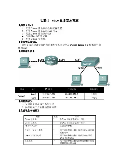
【实验预备知识】:简单复习理论课讲解的路由器配置基本命令及Packet Tracer 5.0模拟软件的使用方法【实验拓扑图】:设备接口IP 地址子网掩码默认网关Router1Fa0/0192.168.1.254 255.255.255.0 不适用Fa0/1192.168.2.254 255.255.255.0 不适用1、预习相关路由器方面的知识2、熟悉相关工具软件的使用方法【实验设备和硬件】:硬件数量说明Cisco 路由器1CCNA 实验室套装的一部分。
Cisco 交换机1CCNA 实验室套装的一部分。
*计算机(主机)1实验室计算机。
控制台(全反)电缆1用于将计算机主机1连接至路由器的控制台端口。
UTP 5 类交叉电缆1用于将计算机主机1连接至路由器的LAN 接口F a0/0直通电缆3用于将计算机主机连接至交换机并将交换机连接至路由器【实验场景】:在本实验中,学生将配置Cisco 路由器的用设置。
【实验内容】:任务1:配置C isco 路由器的全局配置设置。
图1 实验的电缆连接。
步骤1:实际连接设备。
请参阅图1。
将控制台电缆或全反电缆的一端连接至路由器的控制台端口,另一端通过DB-9 或DB-25 适配器连接到主机计算机的C OM 1 端口。
在主机计算机的网卡(NIC) 与路由器的接口F a0/0 之间连接交叉电缆。
在路由器的接口Fa0/1 与交换机的任意接口(1-24) 之间连接直通电缆。
确保主机计算机、交换机和路由器均已通电。
步骤2:通过超级终端将主机计算机连接到路由器。
从Windows 的任务栏中单击“开始”|“程序”|“附件”|“通讯”|“超级终端”启动超级终端程序。
使用正确的设置配置超级终端:当超级终端会话窗口出现后,按Enter 键直到路由器发出响应。
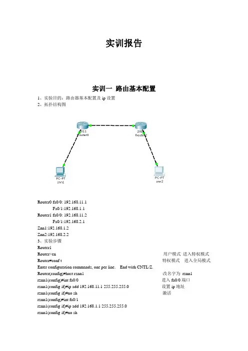
实训报告实训一路由基本配置1、实验目的:路由器基本配置及ip设置2、拓扑结构图Router0 fa0/0: 192.168.11.1Fa0/1:192.168.1.1Router1 fa0/0: 192.168.11.2Fa0/1:192.168.2.1Znn1:192.168.1.2Znn2:192.168.2.23、实验步骤Router1Router>en 用户模式进入特权模式Router#conf t 特权模式进入全局模式Enter configuration commands, one per line. End with CNTL/Z.Router(config)#host rznn1 改名字为rznn1rznn1(config)#int fa0/0 进入fa0/0端口rznn1(config-if)#ip add 192.168.11.1 255.255.255.0 设置ip地址rznn1(config-if)#no sh 激活rznn1(config)#int fa0/1rznn1(config-if)#ip add 192.168.1.1 255.255.255.0rznn1(config-if)#no shrznn1(config-if)#exitrznn1(config)#exitrznn1#copy running-config startup-config 保存Destination filename [startup-config]? startup-configrznn1#conf trznn1(config)#enable secret password 222 设置密文rznn1#show ip interface b 显示Interface IP-Address OK? Method Status Protocol FastEthernet0/0 192.168.11.1 YES manual up up FastEthernet0/1 192.168.1.1 YES manual up upVlan1 unassigned YES manual administratively down downrouter 2outer>enRouter#conf tEnter configuration commands, one per line. End with CNTL/Z.Router(config)#host rznn2rznn2(config)#int fa0/0rznn2(config-if)#ip add 192.168.11.2 255.255.255.0rznn2(config-if)#no shrznn2(config)#int fa0/1rznn2(config-if)#ip add 192.168.2.1 255.255.255.0rznn2(config-if)#no shRznn2#copy running-config startup-config 保存Destination filename [startup-config]? startup-configrznn2(config-if)#exitrznn2(config)#exitrznn2#conf trznn2(config)#enable secret 222rznn2#show ip interface bInterface IP-Address OK? Method Status Protocol FastEthernet0/0 192.168.11.2 YES manual up up FastEthernet0/1 192.168.2.1 YES manual up upVlan1 unassigned YES manual administratively down down实训二1、远程登录、密码设置及验证为路由器开设telnet端口,PC机可以远程登陆到Rznn3(Router 1)拓扑结构图Router0:192.168.1.1Pc:192.168.1.2步骤rznn3>rznn3>enrznn3#conf tEnter configuration commands, one per line. End with CNTL/Z.rznn3(config)#no ip domain lookuprznn3(config)#line cons 0rznn3(config-line)#password znnrznn3(config-line)#loginrznn3(config-line)#no exec-trznn3(config-line)#logg syncrznn3(config-line)#exitrznn3(config)#int fa0/0rznn3(config-if)#ip add 192.168.1.1 255.255.255.0rznn3(config-if)#no shrznn3(config-if)#exitrznn3(config)#line vty 0 4 打通五个端口rznn3(config-line)#password cisco 设置密码rznn3(config-line)#login 保存rznn3(config-line)#exit4、测试:实训三命令组1、目的:八条命令(no ip domain lookup\line cons 0\password\login\no exec-t\logg sync\show version\reload\copy running-config startup-config)\show cdp neighbors)2、拓扑结构图Router0 fa0/0: 192.168.11.1Router1 fa0/0: 192.168.11.23、步骤rznn1#conf tEnter configuration commands, one per line. End with CNTL/Z.1、rznn1(config)#no ip domain lookup 取消域名查找转换2、rznn1(config)#line cons 0 打开cons 0端口3、rznn1(config-line)#password znn 设置密码为znnrznn1(config-line)#login 保存rznn1(config-line)#no exec-t 设置永不超时4、rznn1(config-line)#logg sync 产生日志5、rznn1#show version 显示思科路由系统版本信息Cisco IOS Software, 2800 Software (C2800NM-ADVIPSERVICESK9-M), Version 12.4(15)T1, RELEASE SOFTWARE (fc2)Technical Support: /techsupportCopyright (c) 1986-2007 by Cisco Systems, Inc.Compiled Wed 18-Jul-07 06:21 by pt_rel_team6、rznn1#show cdp neighbors 查看路由器连接的相邻路由器的相关信息Capability Codes: R - Router, T - Trans Bridge, B - Source Route BridgeS - Switch, H - Host, I - IGMP, r - Repeater, P - PhoneDevice ID Local Intrfce Holdtme Capability Platform Port IDrznn2 Fas 0/0 139 R C2800 Fas 0/07、rznn1#copy running-config startup-config 保存刚才指令Destination filename [startup-config]? startup-configBuilding configuration...[OK]8、rznn1#reload 重启路由器Proceed with reload? [confirm]System Bootstrap, Version 12.1(3r)T2, RELEASE SOFTWARE (fc1)Copyright (c) 2000 by cisco Systems, Inc.cisco 2811 (MPC860) processor (revision 0x200) with 60416K/5120K bytes of memorySelf decompressing the image :########################################################################## [OK] Restricted Rights Legendrznn1#show ip interface bInterface IP-Address OK? Method Status Protocol FastEthernet0/0 192.168.11.1 YES manual up up FastEthernet0/1 192.168.1.1 YES manual up upVlan1 unassigned YES manual administratively down down9、rznn1(config-if)#ip add 192.168.3.1 255.255.255.0 重置ip地址rznn1#show ip interface bInterface IP-Address OK? Method Status Protocol FastEthernet0/0 192.168.3.1 YES manual up up FastEthernet0/1 192.168.1.1 YES manual up up Vlan1 unassigned YES manual administratively down down实训四发现协议1、实训目的通过发现协议显示路由器相邻路由的端口信息2、拓扑结构Router0:192.168.11.1Router1:fa0/0 192.168.11.2Fa0/1 192.168.12.1Router2:192.168.12.23、步骤R1路由器Router>enRouter#conf tEnter configuration commands, one per line. End with CNTL/Z.Router(config)#host r1r1(config)#int fa0/0r1(config-if)#ip add 192.168.11.1 255.255.255.0r1(config-if)#no sh%LINK-5-CHANGED: Interface FastEthernet0/0, changed state to upr1(config-if)#r1(config-if)#exitr1(config)#exitr1#%SYS-5-CONFIG_I: Configured from console by consoler1#show ip interface bInterface IP-Address OK? Method Status Protocol FastEthernet0/0 192.168.11.1 YES manual up down FastEthernet0/1 unassigned YES manual administratively down downVlan1 unassigned YES manual administratively down downR2 路由器Router>enRouter#conf tEnter configuration commands, one per line. End with CNTL/Z.Router(config)#host r2r2(config)#int fa0/0r2(config-if)#ip add 192.168.11.2 255.255.255.0r2(config-if)#no sh%LINK-5-CHANGED: Interface FastEthernet0/0, changed state to up%LINEPROTO-5-UPDOWN: Line protocol on Interface FastEthernet0/0, changed state to up r2(config-if)#exitr2(config)#exitr2#%SYS-5-CONFIG_I: Configured from console by consoler2#conf tEnter configuration commands, one per line. End with CNTL/Z.r2(config)#int fa0/0r2(config-if)#int fa0/1r2(config-if)#ip add 192.168.12.1 255.255.255.0r2(config-if)#no sh%LINK-5-CHANGED: Interface FastEthernet0/1, changed state to upr2(config-if)#exitr2(config)#exitr2#%SYS-5-CONFIG_I: Configured from console by consoler2#show ip interface bInterface IP-Address OK? Method Status Protocol FastEthernet0/0 192.168.11.2 YES manual up upFastEthernet0/1 192.168.12.1 YES manual up down Vlan1 unassigned YES manual administratively down downR3路由器Router>enRouter#conf tEnter configuration commands, one per line. End with CNTL/Z.Router(config)#host r3r3(config)#int fa0/0r3(config-if)#ip add 192.168.12.2 255.255.255.0r3(config-if)#no sh%LINK-5-CHANGED: Interface FastEthernet0/0, changed state to up%LINEPROTO-5-UPDOWN: Line protocol on Interface FastEthernet0/0, changed state to up r3(config-if)#exitr3(config)#exitr3#%SYS-5-CONFIG_I: Configured from console by consoler3#show ip interface bInterface IP-Address OK? Method Status Protocol FastEthernet0/0 192.168.12.2 YES manual up up FastEthernet0/1 unassigned YES manual administratively down downVlan1 unassigned YES manual administratively down downR1发现邻居r1#show cdp neighborsCapability Codes: R - Router, T - Trans Bridge, B - Source Route BridgeS - Switch, H - Host, I - IGMP, r - Repeater, P - PhoneDevice ID Local Intrfce Holdtme Capability Platform Port IDr2 Fas 0/0 165 R C2800 Fas 0/0R2发现邻居r2#show cdp neighborsCapability Codes: R - Router, T - Trans Bridge, B - Source Route BridgeS - Switch, H - Host, I - IGMP, r - Repeater, P - PhoneDevice ID Local Intrfce Holdtme Capability Platform Port IDr1 Fas 0/0 176 R C1841 Fas 0/0r3 Fas 0/1 130 R C1841 Fas 0/0R3发现邻居r3#show cdp neighborsCapability Codes: R - Router, T - Trans Bridge, B - Source Route BridgeS - Switch, H - Host, I - IGMP, r - Repeater, P - PhoneDevice ID Local Intrfce Holdtme Capability Platform Port IDr2 Fas 0/0 166 R C2800 Fas 0/14、总结show 命令(1)show ip interface b (显示端口ip信息)(2)show version (显示ios版本信息)(3)show running-config (显示刚才使用的命令配置信息)(4)show cdp neighbors (显示发现邻居直连设备信息)(5)show interface (显示所有端口详细信息)实训五静态路由1、实验目的:将不同网段的网络配通(ip route)Ip route语法:ip route 目标地址子网掩码相邻路由器接口地址Show ip route2、试验拓扑:Router0:192.168.11.1Router1:fa0/0 192.168.11.2Fa0/1 192.168.12.1Router2:192.168.12.23、实验步骤:Router1Router>enRouter#conf tRouter(config)#host r1r1(config)#int fa0/0r1(config-if)#ip add 192.168.11.1 255.255.255.0r1(config-if)#no sh%LINK-5-CHANGED: Interface FastEthernet0/0, changed state to upr1(config-if)#exitr1(config)#exitr1#show ip interface bInterface IP-Address OK? Method Status ProtocolFastEthernet0/0 192.168.11.1 YES manual up downFastEthernet0/1 unassigned YES manual administratively down downVlan1 unassigned YES manual administratively down downr1#%LINEPROTO-5-UPDOWN: Line protocol on Interface FastEthernet0/0, changed state to up r1#ping 192.168.12.1Type escape sequence to abort.Sending 5, 100-byte ICMP Echos to 192.168.12.1, timeout is 2 seconds:.....Success rate is 0 percent (0/5)r1#conf tEnter configuration commands, one per line. End with CNTL/Z.r1(config)#ip route 192.168.12.0 255.255.255.0 192.168.11.2r1(config)#exitr1#ping 192.168.12.1Type escape sequence to abort.Sending 5, 100-byte ICMP Echos to 192.168.12.1, timeout is 2 seconds:Success rate is 100 percent (5/5), round-trip min/avg/max = 31/31/32 msr1#ping 192.168.12.2Type escape sequence to abort.Sending 5, 100-byte ICMP Echos to 192.168.12.2, timeout is 2 seconds:.....Success rate is 0 percent (0/5)r1#ping 192.168.12.2Type escape sequence to abort.Sending 5, 100-byte ICMP Echos to 192.168.12.2, timeout is 2 seconds:Success rate is 100 percent (5/5), round-trip min/avg/max = 47/62/78 msr1#show ip routeCodes: C - connected, S - static, I - IGRP, R - RIP, M - mobile, B - BGPD - EIGRP, EX - EIGRP external, O - OSPF, IA - OSPF inter areaN1 - OSPF NSSA external type 1, N2 - OSPF NSSA external type 2E1 - OSPF external type 1, E2 - OSPF external type 2, E - EGPi - IS-IS, L1 - IS-IS level-1, L2 - IS-IS level-2, ia - IS-IS inter area* - candidate default, U - per-user static route, o - ODRP - periodic downloaded static routeGateway of last resort is not setC 192.168.11.0/24 is directly connected, FastEthernet0/0S 192.168.12.0/24 [1/0] via 192.168.11.2Router3Router>enRouter#conf tEnter configuration commands, one per line. End with CNTL/Z.Router(config)#host r3r3(config)#int fa0/0r3(config-if)#ip add 192.168.12.2 255.255.255.0r3(config-if)#no sh%LINK-5-CHANGED: Interface FastEthernet0/0, changed state to up%LINEPROTO-5-UPDOWN: Line protocol on Interface FastEthernet0/0, changed state to up r3(config-if)#exitr3(config)#exitr3#%SYS-5-CONFIG_I: Configured from console by consoler3#show ip interface bInterface IP-Address OK? Method Status Protocol FastEthernet0/0 192.168.12.2 YES manual up up FastEthernet0/1 unassigned YES manual administratively down downVlan1 unassigned YES manual administratively down downr3#conf tEnter configuration commands, one per line. End with CNTL/Z.r3(config)#ip route 192.168.11.0 255.255.255.0 192.168.12.1r3(config)#exitr3#ping 192.168.11.2Type escape sequence to abort.Sending 5, 100-byte ICMP Echos to 192.168.11.2, timeout is 2 seconds:Success rate is 100 percent (5/5), round-trip min/avg/max = 31/31/32 msr3#ping 192.168.11.1Type escape sequence to abort.Sending 5, 100-byte ICMP Echos to 192.168.11.1, timeout is 2 seconds:Success rate is 100 percent (5/5), round-trip min/avg/max = 62/62/63 msr3#show ip routeCodes: C - connected, S - static, I - IGRP, R - RIP, M - mobile, B - BGPD - EIGRP, EX - EIGRP external, O - OSPF, IA - OSPF inter areaN1 - OSPF NSSA external type 1, N2 - OSPF NSSA external type 2i - IS-IS, L1 - IS-IS level-1, L2 - IS-IS level-2, ia - IS-IS inter area* - candidate default, U - per-user static route, o - ODRP - periodic downloaded static routeGateway of last resort is not setS 192.168.11.0/24 [1/0] via 192.168.12.1C 192.168.12.0/24 is directly connected, FastEthernet0/04、默认路由Route 1r1>enr1#conf tEnter configuration commands, one per line. End with CNTL/Z.r1(config)#no ip route 192.168.12.0 255.255.255.0 192.168.11.2%No matching route to deleter1(config)#exitr1#%SYS-5-CONFIG_I: Configured from console by consoler1#show ip routeCodes: C - connected, S - static, I - IGRP, R - RIP, M - mobile, B - BGPD - EIGRP, EX - EIGRP external, O - OSPF, IA - OSPF inter areaN1 - OSPF NSSA external type 1, N2 - OSPF NSSA external type 2E1 - OSPF external type 1, E2 - OSPF external type 2, E - EGPi - IS-IS, L1 - IS-IS level-1, L2 - IS-IS level-2, ia - IS-IS inter area* - candidate default, U - per-user static route, o - ODRP - periodic downloaded static routeGateway of last resort is not setC 192.168.11.0/24 is directly connected, FastEthernet0/0r1#conf tEnter configuration commands, one per line. End with CNTL/Z.r1(config)#ip route 0.0.0.0 0.0.0.0 192.168.11.2r1(config)#exitr1#%SYS-5-CONFIG_I: Configured from console by consoler1#show ip routeCodes: C - connected, S - static, I - IGRP, R - RIP, M - mobile, B - BGPD - EIGRP, EX - EIGRP external, O - OSPF, IA - OSPF inter areaN1 - OSPF NSSA external type 1, N2 - OSPF NSSA external type 2i - IS-IS, L1 - IS-IS level-1, L2 - IS-IS level-2, ia - IS-IS inter area* - candidate default, U - per-user static route, o - ODRP - periodic downloaded static routeGateway of last resort is 192.168.11.2 to network 0.0.0.0C 192.168.11.0/24 is directly connected, FastEthernet0/0S* 0.0.0.0/0 [1/0] via 192.168.11.2r1#ping 192.168.12.1Type escape sequence to abort.Sending 5, 100-byte ICMP Echos to 192.168.12.1, timeout is 2 seconds:Success rate is 100 percent (5/5), round-trip min/avg/max = 16/28/31 msr1#ping 192.168.12.2Type escape sequence to abort.Sending 5, 100-byte ICMP Echos to 192.168.12.2, timeout is 2 seconds: Success rate is 100 percent (5/5), round-trip min/avg/max = 62/62/63 msRoute 3r1>enr1#conf tEnter configuration commands, one per line. End with CNTL/Z.r1(config)#no ip route 192.168.12.0 255.255.255.0 192.168.11.2%No matching route to deleter1(config)#exitr1#%SYS-5-CONFIG_I: Configured from console by consoler1#show ip routeCodes: C - connected, S - static, I - IGRP, R - RIP, M - mobile, B - BGPD - EIGRP, EX - EIGRP external, O - OSPF, IA - OSPF inter areaN1 - OSPF NSSA external type 1, N2 - OSPF NSSA external type 2E1 - OSPF external type 1, E2 - OSPF external type 2, E - EGPi - IS-IS, L1 - IS-IS level-1, L2 - IS-IS level-2, ia - IS-IS inter area* - candidate default, U - per-user static route, o - ODRP - periodic downloaded static routeGateway of last resort is not setC 192.168.11.0/24 is directly connected, FastEthernet0/0r1#conf tEnter configuration commands, one per line. End with CNTL/Z.r1(config)#ip route 0.0.0.0 0.0.0.0 192.168.11.2r1(config)#exitr1#%SYS-5-CONFIG_I: Configured from console by consoler1#show ip routeCodes: C - connected, S - static, I - IGRP, R - RIP, M - mobile, B - BGPD - EIGRP, EX - EIGRP external, O - OSPF, IA - OSPF inter areaN1 - OSPF NSSA external type 1, N2 - OSPF NSSA external type 2E1 - OSPF external type 1, E2 - OSPF external type 2, E - EGPi - IS-IS, L1 - IS-IS level-1, L2 - IS-IS level-2, ia - IS-IS inter area* - candidate default, U - per-user static route, o - ODRP - periodic downloaded static routeGateway of last resort is 192.168.11.2 to network 0.0.0.0C 192.168.11.0/24 is directly connected, FastEthernet0/0S* 0.0.0.0/0 [1/0] via 192.168.11.2r3#ping 192.168.11.1Type escape sequence to abort.Sending 5, 100-byte ICMP Echos to 192.168.11.1, timeout is 2 seconds: Success rate is 100 percent (5/5), round-trip min/avg/max = 62/62/63 ms实训六动态路由RIP 协议1、实验目的使用配置动态路由启动Rip协议使用到的命令(router rip/network/show ip protocols/show ip route)2、实验拓扑R1 fa0/0 192.168.11.1R2 fa0/0 192.168.11.2fa0/1 192.168.12.1R3 fa0/0 192.168.12.23、实验步骤R1Router>enRouter#conf tEnter configuration commands, one per line. End with CNTL/Z. Router(config)#host r1r1(config)#int fa0/0r1(config-if)#ip add 192.168.11.1 255.255.255.0r1(config-if)#no shr1(config-if)#exitr1(config)#router ripr1(config-router)#network 192.168.11.0r1(config-router)#exitr1(config)#exitr1#%SYS-5-CONFIG_I: Configured from console by consoleR2Router>enRouter#conf tEnter configuration commands, one per line. End with CNTL/Z. Router(config)#host r2r2(config)#int fa0/0r2(config-if)#ip add 192.168.11.2 255.255.255.0r2(config-if)#no shr2(config-if)#exitr2(config)#int fa0/1r2(config-if)#ip add 192.168.12.1 255.255.255.0r2(config-if)#no shr2(config-if)#exitr2(config)#router ripr2(config-router)#network 192.168.11.0r2(config-router)#network 192.168.12.0r2(config-router)#exitr2(config)#exitr2#R3Router>enRouter#conf tEnter configuration commands, one per line. End with CNTL/Z. Router(config)#host r3r3(config)#int fa0/0r3(config-if)#ip add 192.168.12.2 255.255.255.0r3(config-if)#no shr3(config-if)#exitr3(config)#router ripr3(config-router)#network 192.168.12.0r3(config-router)#exitr3(config)#exitr3#%SYS-5-CONFIG_I: Configured from console by console4、实验测试R1r1#show ip protocolsRouting Protocol is "rip"Sending updates every 30 seconds, next due in 10 secondsInvalid after 180 seconds, hold down 180, flushed after 240 Outgoing update filter list for all interfaces is not setIncoming update filter list for all interfaces is not set Redistributing: ripDefault version control: send version 1, receive any version Interface Send Recv Triggered RIP Key-chain FastEthernet0/0 1 2 1Automatic network summarization is in effectMaximum path: 4Routing for Networks:192.168.11.0Passive Interface(s):Routing Information Sources:Gateway Distance Last UpdateDistance: (default is 120)r1#show ip routeCodes: C - connected, S - static, I - IGRP, R - RIP, M - mobile, B - BGPD - EIGRP, EX - EIGRP external, O - OSPF, IA - OSPF inter areaN1 - OSPF NSSA external type 1, N2 - OSPF NSSA external type 2E1 - OSPF external type 1, E2 - OSPF external type 2, E - EGPi - IS-IS, L1 - IS-IS level-1, L2 - IS-IS level-2, ia - IS-IS inter area* - candidate default, U - per-user static route, o - ODRP - periodic downloaded static routeGateway of last resort is not setC 192.168.11.0/24 is directly connected, FastEthernet0/0R 192.168.12.0/24 [120/1] via 192.168.11.2, 00:00:24, FastEthernet0/0 r1#ping 192.168.12.0Type escape sequence to abort.Sending 5, 100-byte ICMP Echos to 192.168.12.0, timeout is 2 seconds: Success rate is 100 percent (5/5), round-trip min/avg/max = 31/31/32 msR2r2#show ip protocolsRouting Protocol is "rip"Sending updates every 30 seconds, next due in 21 secondsInvalid after 180 seconds, hold down 180, flushed after 240Outgoing update filter list for all interfaces is not setIncoming update filter list for all interfaces is not setRedistributing: ripDefault version control: send version 1, receive any versionInterface Send Recv Triggered RIP Key-chain FastEthernet0/0 1 2 1FastEthernet0/1 1 2 1Automatic network summarization is in effectMaximum path: 4Routing for Networks:192.168.11.0192.168.12.0Passive Interface(s):Routing Information Sources:Gateway Distance Last UpdateDistance: (default is 120)r2#show ip routeCodes: C - connected, S - static, I - IGRP, R - RIP, M - mobile, B - BGPD - EIGRP, EX - EIGRP external, O - OSPF, IA - OSPF inter areaN1 - OSPF NSSA external type 1, N2 - OSPF NSSA external type 2E1 - OSPF external type 1, E2 - OSPF external type 2, E - EGPi - IS-IS, L1 - IS-IS level-1, L2 - IS-IS level-2, ia - IS-IS inter area* - candidate default, U - per-user static route, o - ODRP - periodic downloaded static routeGateway of last resort is not setC 192.168.11.0/24 is directly connected, FastEthernet0/0C 192.168.12.0/24 is directly connected, FastEthernet0/1R3r3#show ip protocolsRouting Protocol is "rip"Sending updates every 30 seconds, next due in 15 secondsInvalid after 180 seconds, hold down 180, flushed after 240Outgoing update filter list for all interfaces is not setIncoming update filter list for all interfaces is not setRedistributing: ripDefault version control: send version 1, receive any versionInterface Send Recv Triggered RIP Key-chain FastEthernet0/0 1 2 1Automatic network summarization is in effectMaximum path: 4Routing for Networks:192.168.12.0Passive Interface(s):Routing Information Sources:Gateway Distance Last UpdateDistance: (default is 120)r3#show ip routeCodes: C - connected, S - static, I - IGRP, R - RIP, M - mobile, B - BGPD - EIGRP, EX - EIGRP external, O - OSPF, IA - OSPF inter areaN1 - OSPF NSSA external type 1, N2 - OSPF NSSA external type 2E1 - OSPF external type 1, E2 - OSPF external type 2, E - EGPi - IS-IS, L1 - IS-IS level-1, L2 - IS-IS level-2, ia - IS-IS inter area* - candidate default, U - per-user static route, o - ODRP - periodic downloaded static routeGateway of last resort is not setR 192.168.11.0/24 [120/1] via 192.168.12.1, 00:00:04, FastEthernet0/0 C 192.168.12.0/24 is directly connected, FastEthernet0/0r3#ping 192.168.11.0Type escape sequence to abort.Sending 5, 100-byte ICMP Echos to 192.168.11.0, timeout is 2 seconds: Success rate is 100 percent (5/5), round-trip min/avg/max = 31/31/32 ms实训七负载平衡试训目的实现负载平衡实训拓扑R1 fa0/0 192.168.11.1R2 eth0/0/0 192.168.11.2Fa0/0 192.168.12.1Fa0/0 192.168.13.1R3 fa0/0 192.168.12.2Fa0/1 192.168.14.1R4 fa0/0 192.168.13.2Fa0/1 192.168.15.1R5 fa0/0 192.168.14.2Fa0/1 192.168.15.2实训步骤(R1 )r1>enR1#conf tR1(config)#ip route 0.0.0.0 0.0.0.0 192.168.11.2R1(config)#exitr1#show ip routeCodes: C - connected, S - static, I - IGRP, R - RIP, M - mobile, B - BGPD - EIGRP, EX - EIGRP external, O - OSPF, IA - OSPF inter areaN1 - OSPF NSSA external type 1, N2 - OSPF NSSA external type 2E1 - OSPF external type 1, E2 - OSPF external type 2, E - EGPi - IS-IS, L1 - IS-IS level-1, L2 - IS-IS level-2, ia - IS-IS inter area* - candidate default, U - per-user static route, o - ODRP - periodic downloaded static routeGateway of last resort is 192.168.11.2 to network 0.0.0.0C 192.168.11.0/24 is directly connected, FastEthernet0/0S* 0.0.0.0/0 [1/0] via 192.168.11.2(R2)r2>enr2(config)#ip route 0.0.0.0 0.0.0.0 192.168.12.2r2(config)#ip route 0.0.0.0 0.0.0.0 192.168.13.2r2(config)#exitr2#%SYS-5-CONFIG_I: Configured from console by consoles% Ambiguous command: "s"r2#show ip routeCodes: C - connected, S - static, I - IGRP, R - RIP, M - mobile, B - BGPD - EIGRP, EX - EIGRP external, O - OSPF, IA - OSPF inter areaN1 - OSPF NSSA external type 1, N2 - OSPF NSSA external type 2E1 - OSPF external type 1, E2 - OSPF external type 2, E - EGPi - IS-IS, L1 - IS-IS level-1, L2 - IS-IS level-2, ia - IS-IS inter area* - candidate default, U - per-user static route, o - ODRP - periodic downloaded static routeGateway of last resort is 192.168.12.2 to network 0.0.0.0C 192.168.11.0/24 is directly connected, Ethernet0/0/0C 192.168.12.0/24 is directly connected, FastEthernet0/0C 192.168.13.0/24 is directly connected, FastEthernet0/1S* 0.0.0.0/0 [1/0] via 192.168.12.2[1/0] via 192.168.13.2(R3)r3>enr3#conf tEnter configuration commands, one per line. End with CNTL/Z.r3(config)#ip route 0.0.0.0 0.0.0.0 192.168.12.1r3(config)#exitr3#%SYS-5-CONFIG_I: Configured from console by consoler3#show ip routeCodes: C - connected, S - static, I - IGRP, R - RIP, M - mobile, B - BGPD - EIGRP, EX - EIGRP external, O - OSPF, IA - OSPF inter areaN1 - OSPF NSSA external type 1, N2 - OSPF NSSA external type 2E1 - OSPF external type 1, E2 - OSPF external type 2, E - EGPi - IS-IS, L1 - IS-IS level-1, L2 - IS-IS level-2, ia - IS-IS inter area* - candidate default, U - per-user static route, o - ODRP - periodic downloaded static routeGateway of last resort is 192.168.12.1 to network 0.0.0.0C 192.168.12.0/24 is directly connected, FastEthernet0/0C 192.168.14.0/24 is directly connected, FastEthernet0/1S* 0.0.0.0/0 [1/0] via 192.168.12.1(R4)r4>enr4#conf tEnter configuration commands, one per line. End with CNTL/Z.r4(config)#ip route 0.0.0.0 0.0.0.0 192.168.13.1r4(config)#exitr4#%SYS-5-CONFIG_I: Configured from console by consoler4#show ip routeCodes: C - connected, S - static, I - IGRP, R - RIP, M - mobile, B - BGPD - EIGRP, EX - EIGRP external, O - OSPF, IA - OSPF inter areaN1 - OSPF NSSA external type 1, N2 - OSPF NSSA external type 2E1 - OSPF external type 1, E2 - OSPF external type 2, E - EGPi - IS-IS, L1 - IS-IS level-1, L2 - IS-IS level-2, ia - IS-IS inter area* - candidate default, U - per-user static route, o - ODRP - periodic downloaded static routeGateway of last resort is 192.168.13.1 to network 0.0.0.0C 192.168.13.0/24 is directly connected, FastEthernet0/0C 192.168.15.0/24 is directly connected, FastEthernet0/1S* 0.0.0.0/0 [1/0] via 192.168.13.1(R5)r5>enr5#conf tEnter configuration commands, one per line. End with CNTL/Z.r5(config)#ip route 0.0.0.0 0.0.0.0 192.168.14.1r5(config)#ip route 0.0.0.0 0.0.0.0 192.168.15.1r5(config)#exitr5#%SYS-5-CONFIG_I: Configured from console by consoler5#show ip routeCodes: C - connected, S - static, I - IGRP, R - RIP, M - mobile, B - BGPD - EIGRP, EX - EIGRP external, O - OSPF, IA - OSPF inter areaN1 - OSPF NSSA external type 1, N2 - OSPF NSSA external type 2E1 - OSPF external type 1, E2 - OSPF external type 2, E - EGPi - IS-IS, L1 - IS-IS level-1, L2 - IS-IS level-2, ia - IS-IS inter area* - candidate default, U - per-user static route, o - ODRP - periodic downloaded static routeGateway of last resort is 192.168.14.1 to network 0.0.0.0C 192.168.14.0/24 is directly connected, FastEthernet0/0C 192.168.15.0/24 is directly connected, FastEthernet0/1S* 0.0.0.0/0 [1/0] via 192.168.14.1[1/0] via 192.168.15.1实训测试(R1)r1#ping 192.168.14.1Type escape sequence to abort.Sending 5, 100-byte ICMP Echos to 192.168.14.1, timeout is 2 seconds:Success rate is 100 percent (5/5), round-trip min/avg/max = 62/84/94 ms (R5)r5#ping 192.168.11.1Type escape sequence to abort.Sending 5, 100-byte ICMP Echos to 192.168.11.1, timeout is 2 seconds: Success rate is 100 percent (5/5), round-trip min/avg/max = 79/91/94 ms实训八DHCP 协议配置实训目的全网配通实训拓扑Fa0/0 192.168.11.1Fa0/1 192.168.12.1实训步骤Router>enRouter#conf tEnter configuration commands, one per line. End with CNTL/Z.Router(config)#host r1r1(config)#int fa0/0r1(config-if)#ip add 192.168.11.1 255.255.255.0r1(config-if)#no shr1(config-if)#exitr1(config)#int fa0/1r1(config-if)#ip add 192.168.12.1 255.255.255.0r1(config-if)#no shr1(config-if)#exitr1(config)#ip dhcp pool znn //配置一个根地址池znnr1(dhcp-config)#network 192.168.11.0 255.255.255.0 //为所有客户机动态分配的地址段r1(dhcp-config)#default-router 192.168.11.1 //为客户机配置默认的网关r1(dhcp-config)#dns-server 192.168.11.1 //为客户机配置DNS服务器r1(dhcp-config)#exitr1(config)#ip dhcp pool znn1r1(dhcp-config)#network 192.168.12.0 255.255.255.0r1(dhcp-config)#default-router 192.168.12.1r1(dhcp-config)#dns-server 192.168.12.1r1(dhcp-config)#exit。

cisco配置实验报告Cisco配置实验报告1. 实验目的本次实验旨在通过配置Cisco网络设备,实现局域网内主机之间的互联及互访。
通过此实验,我们将深入了解Cisco设备的配置和管理,提高网络管理技能。
2. 实验环境本次实验使用的设备为Cisco Catalyst 2960交换机和Cisco 2811路由器。
交换机用于构建局域网,路由器用于实现不同局域网之间的互联。
3. 实验步骤3.1 网络拓扑规划根据实验要求,我们设计了以下网络拓扑结构:一个核心交换机连接多个分支交换机,每个分支交换机连接多台主机。
核心交换机通过路由器与其他局域网相连。
3.2 配置交换机首先,我们登录到核心交换机的管理界面。
使用默认用户名和密码登录后,我们进入交换机的命令行界面。
3.2.1 VLAN配置为了实现不同局域网之间的隔离,我们需要配置不同的VLAN。
通过以下命令,我们创建了两个VLAN,分别为VLAN 10和VLAN 20:```vlan 10name VLAN10vlan 20name VLAN20```3.2.2 端口配置接下来,我们需要将交换机的端口划分到不同的VLAN中。
通过以下命令,我们将端口1-10划分到VLAN 10,端口11-20划分到VLAN 20:```interface range fastEthernet 0/1-10switchport mode accessswitchport access vlan 10interface range fastEthernet 0/11-20switchport mode accessswitchport access vlan 20```3.3 配置路由器在路由器上,我们需要配置静态路由,将不同局域网之间的流量进行转发。
3.3.1 接口配置首先,我们配置路由器的接口。
通过以下命令,我们将路由器的Fa0/0接口配置为与核心交换机相连的接口:```interface fastEthernet 0/0ip address 192.168.1.1 255.255.255.0```3.3.2 静态路由配置接着,我们配置静态路由,实现不同局域网之间的互通。

千里之行,始于足下。
计算机网络》实验二 CISCO交换机的基本操作实验报告计算机网络》实验二 CISCO交换机的基本操作实验报告摘要:计算机网络的使用已经变得日常化,而交换机作为网络中常见的设备,对网络的稳定运行起着重要的作用。
本实验旨在通过对CISCO交换机的基本操作进行实践,加深对交换机工作原理的理解,掌握交换机的基本配置和网络故障排除等技能。
本文将详细介绍实验过程及结果,并对实验中所遇到的问题和解决方法进行讨论。
一、引言计算机网络是现代社会中信息传输的基础设施,其中交换机作为实现计算机之间进行数据传输和通信的关键设备,对网络的稳定运行起着重要的作用。
本实验通过对CISCO交换机的基本操作进行实践,旨在加深对交换机工作原理的理解,并掌握交换机的基本配置和故障排除等技能。
二、实验目的1. 掌握CISCO交换机的基本使用方法和操作步骤;2. 理解交换机的工作原理和基本配置;3. 能够进行交换机的基本配置和故障排除。
三、实验步骤及结果1. 实验环境准备(1) 操作系统:Windows 10;(2) 软件:PuTTY、CISCO交换机模拟器。
第1页/共3页锲而不舍,金石可镂。
2. 实验步骤(1) 打开PuTTY,通过SSH协议连接到CISCO交换机模拟器;(2) 输入用户名和密码以登录交换机;(3) 配置交换机的基本信息,如主机名、IP地址、子网掩码等;(4) 配置交换机的端口 VLAN 和端口模式;(5) 配置交换机的端口速率和双工模式;(6) 进行网络连通性测试,检查配置是否成功。
3. 实验结果及分析经过实验操作,成功登录CISCO交换机,并按照实验指导书要求进行了基本配置。
通过网络连通性测试,确认配置生效,并能正常进行数据传输和通信。
实验结果表明,基本操作步骤能够顺利实现,并取得了预期的实验效果。
四、问题与解决1. 问题1:无法连接到CISCO交换机。
解决方法:检查网络连接是否正常,重新配置PuTTY连接参数。

《计算机网络技术》实验指导书:Cisco路由器的基本配置【实验目的】:1.熟练使用超级终端对路由器进行配置2.学习路由器命令3.掌握路由器的基本连接和配置【实验内容】:1.超级终端的使用2.路由器的启动和初始配置3.路由器的常规配置【实验原理及相关知识】:路由器可以用来连通不同的网络,并且能够选择信息传送的路径。
选择通畅快捷的路径,能大大提高信息速度,减轻网络系统通信负荷,节约网络系统资源,提高网络系统畅通率,从而让网络系统发挥出更大的效益。
从过滤网络流量的角度来看,路由器的作用与交换机、网桥非常相似。
但是与工作在网络底层、从物理上划分网段的交换机不同,路由器使用专门的软件协议从逻辑上对整个网络进行划分。
例如,一台支持IP协议的路由器可以把网络划分成多个子网络,只有网间的网络流量才可以通过路由器。
对于每一个接收到的数据包,路由器都会重新计算其校验值,并写入新的物理地址。
因此使用路由器转发和过滤数据的速度往往要比只查看数据包物理地址的交换机慢,但是对于那些结构复杂的网络,使用路由器可以提高网络的整体效率。
路由器的另一个明显优势就是可以自动过滤网络广播。
总体来说,在网络中添加路由器的整个安装过程要比安装即插即用的交换机复杂的多。
一般来说,异种网络互联或多个子网互联都应采用路由器来完成。
路由器的主要工作就是为经过路由的每个数据包寻找一条最佳的传输路径,并将该数据有效地址传送到目的站点。
由此可见,选择最佳路径的策略是路由器的关键所在。
为了完成这项工作,在路由表中保存着子网的标志信息、网上路由的个数和下一个路由器的名字等内容。
路由表可以由系统管理员固定设置,也可以由系统动态修改;可以由路由器自动调整,也可以由主机控制。
路由器的构成从硬件组成上来看,路由器由CPU、内存和接口等部分组成。
1 CPU路由器和PC机一样,有中央处理单元CPU,CPU是路由器的处理中心。
对于不同的路由器,其CPU一般也不一样。
2 内存内存用来存储路由器的信息和数据,Cisco路由器有以下几种内存组件:(1)ROM(Read Only Memory)ROM中存储路由器加电自检程序(Power-On Self-Test Program)启动程序(Bootstrap Program)和部分或全部的IOS。
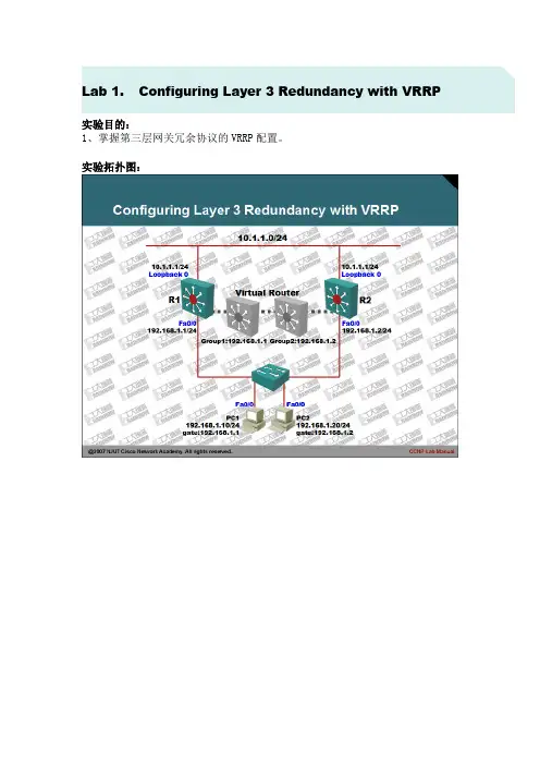
Lab 1.Configuring Layer 3 Redundancy with VRRP
实验目的:
1、掌握第三层网关冗余协议的VRRP配置。
实验拓扑图:
实验步骤及要求:
1、本实验可以使用三层交换机完成,也可以使用路由器完成,在使用路由器时需要注意IOS的版本,确认支持HSRP协议。
2、配置PC1与PC2路由器,将其模拟成主机,配置如下:
3、首先在PC1和PC2上使用ping和traceroute命令,确认网络是否可达:
4、将R1路由器的FA0/0接口,置为down状态:
5、再次在R1和R2上使用ping和traceroute命令测试:
6、虽然有两台路由器都可以到达目标网络,但是默认情况下,并没有充分利用冗余设备,因此当网络单点出错时,必然会引起部分用户无法访问网络。
7、为了解决这一问题,在R1和R2上配置VRRP协议,配置如下:
8、通过查看两台路由器的VRRP组汇总信息,确认不同路由器的组身份:
9、再次把R1路由器的Fa0/0接口置为DOWN状态,两台路由器将会出现如下信息:
10、再次在R1和R2上使用ping和traceroute确认:
11、由于在网络中启用了两个不同的VRRP组,所以最大限度上确保了网络冗余。
同时为了更好的观察VRRP的工作过程,建议在R1和R2路由器上使用扩展的PING 命令持续向目标网络发送数据包。
同时在R1和R2路由器使用如下命令进行调试,具体不再列出:
12、实验完成。
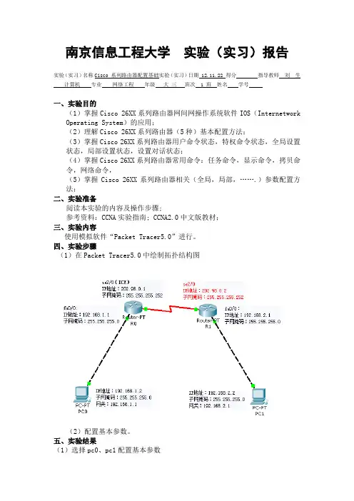
南京信息工程大学实验(实习)报告实验(实习)名称Cisco 系列路由器配置基础实验(实习)日期 12.11.22 得分指导教师刘生计算机专业网络工程年级大三班次 1 班姓名学号一、实验目的(1)掌握Cisco 26XX系列路由器网间网操作系统软件IOS(Internetwork Operating System)的应用;(2)理解Cisco 26XX系列路由器(5种)基本配置方法;(3)掌握Cisco 26XX系列路由器用户命令状态,特权命令状态,全局设置状态,局部设置状态,设置对话状态;(4)掌握Cisco 26XX系列路由器常用命令:任务命令,显示命令,拷贝命令,网络命令,(5)掌握Cisco 26XX系列路由器相关(全局,局部,…….)参数配置方法;二、实验准备阅读本实验的内容及操作步骤;参考资料:CCNA实验指南; CCNA2.0中文版教材;三、实验内容使用模拟软件“Packet Tracer5.0”进行。
四、实验步骤(1)在Packet Tracer5.0中绘制拓扑结构图(2)配置基本参数。
五、实验结果(1)选择pc0、pc1配置基本参数(2)选择R0.输入以下命令:Route> enableRoute# conf t(切换到配置状态)Route# hostname R0R0(config)#int Fa0/0(配置快速Ethernet 0端口)R0(config-if)#ip add 192.168.1.1 255.255.255.0(定义以太网IP地址,子网掩码表示为C类网络默认子网掩码)R0(config-if)#no shut(激活端口)R0(config-if)#int se2/0(配置Serial 0口)R0(config-if)#ip add 202.98.0.1 255.255.255.252(定义互联广域网IP地址)R0(config-if)#clock rate 64000R0(config-if)#no shut(激活端口)R0(config)#ip route 192.168.2.0 255.255.255.0 202.98.0.2(定义静态路由,通过网关到达对端局域网络,IP为对端广域网IP地址)R0(config)#endR0#copy run start(保存配置)R0#show ip route(3)选择R1.输入以下命令:Route> enableRoute# conf t(切换到配置状态)Route# hostname R1R1(config)#int Fa0/0(配置快速Ethernet 0端口)R1(config-if)#ip add 192.168.2.1 255.255.255.0(定义以太网IP地址,子网掩码表示为C类网络)R1(config-if)#no shut(激活端口)R1(config-if)#int se2/0(配置Serial 0口)R1(config-if)#ip add 202.98.0.2 255.255.255.252(定义互联广域网IP地址)R1(config-if)#no shut(激活端口)R1(config)#ip route 192.168.1.0 255.255.255.0 202.98.0.1(定义静态路由,通过网关到达对端局域网络,IP为对端广域网IP地址)R1(config)#endR1#copy run start(保存配置)R1#show ip route(4)选择PC0.输入以下命令:Ping 192.168.2.2Tracert 192.168.2.2查看运行结果六、实验总结通过这次实验,由于要对路由器进行配置,所以必须小心谨慎,一个不留神就会敲错代码,导致错误,需退回上一级,重新进入。

Cisco交换机配置实验报告实验目的本实验旨在了解和掌握Cisco交换机的基本配置和操作方法,包括VLAN划分、端口配置、静态路由等。
实验环境•Cisco交换机(型号:XYZ)•一台计算机•Console连接线实验步骤步骤一:连接设备1.将计算机通过Console连接线与Cisco交换机的Console端口相连。
2.打开终端软件(如SecureCRT、PuTTY等),配置串口连接参数,如波特率、数据位、停止位等。
3.点击连接按钮,与Cisco交换机建立串口连接。
步骤二:进入特权模式1.在终端中输入用户名和密码,登录到Cisco交换机的用户模式。
2.输入enable命令,进入特权模式,需输入特权密码。
步骤三:配置主机名1.在特权模式下,输入configure terminal命令,进入全局配置模式。
2.输入hostname [名称]命令,设置Cisco交换机的主机名。
3.按下Ctrl+Z保存配置并退出。
步骤四:配置VLAN1.进入全局配置模式,输入vlan [VLAN编号]命令,创建VLAN。
2.输入name [VLAN名称]命令,为VLAN设置名称。
3.重复以上步骤,创建所需的所有VLAN。
4.按下Ctrl+Z保存配置并退出。
步骤五:配置端口1.进入全局配置模式,输入interface [端口编号]命令,进入端口配置模式。
2.输入switchport mode access命令,设置端口为访问模式。
3.输入switchport access vlan [VLAN编号]命令,将端口划分到对应的VLAN。
4.重复以上步骤,配置所有需要的端口。
5.按下Ctrl+Z保存配置并退出。
步骤六:配置静态路由1.进入全局配置模式,输入ip route [目标子网] [子网掩码] [下一跳地址]命令,添加静态路由。
2.重复以上步骤,配置所有需要的静态路由。
3.按下Ctrl+Z保存配置并退出。
步骤七:查看配置1.在特权模式下,输入show running-config命令,查看当前的运行配置。
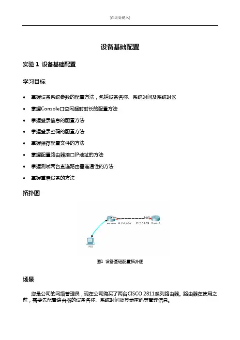
[在此处键入]设备基础配置实验1 设备基础配置学习目标•掌握设备系统参数的配置方法,包括设备名称、系统时间及系统时区•掌握Console口空闲超时时长的配置方法•掌握登录信息的配置方法•掌握登录密码的配置方法•掌握保存配置文件的方法•掌握配置路由器接口IP地址的方法•掌握测试两台直连路由器连通性的方法•掌握重启设备的方法拓扑图图1 设备基础配置拓扑图场景您是公司的网络管理员,现在公司购买了两台CISCO 2811系列路由器。
路由器在使用之前,需要先配置路由器的设备名称、系统时间及登录密码等管理信息。
操作步骤步骤一进入特权模式CISCO IOS有三种模式即:用户模式(用“>”表示);特权模式(用“#”表示);配置模式(用“(config) #”表示)。
1.用户模式交换机启动完成后按下Enter键,首先进入的就是用户模式,在些用户模式下用户将受到极大的限制,只能用来查看一些统计信息。
Switch>2.特权模式在用户模式下输入enable(可简写为en)命令就可以进入特权模式,用户在该模式下可以查看并修改Cisco设备的配置。
Switch>enSwitch#3.全局配置模式在特权模式下输入config terminal(可简写conf t)命令即可,用户在该模式下可修改交换机的全局配置。
如修改主机名。
Switch#conf tSwitch(config)#4.各模式退出命令,在任意模式下输入exit,将退出当前模式。
步骤二查看系统信息执行show version命令,查看路由器的软件版本与硬件信息。
Router#show version(截图)命令回显信息中包含了IOS版本,设备型号等信息。
步骤三修改系统时间执行show clock命令查看当前系统时间。
Router#show clock(截图)IOS系统会自动保存时间,但如果时间不正确,可以在特权模式下执行clock set命令修改系统时间。
路由器的配置实验完整报告1. 实验目的本实验旨在通过配置路由器,了解路由器的工作原理和实际应用,并掌握路由器的基本操作和配置方法。
2. 实验环境本实验使用Cisco Packet Tracer网络仿真工具进行配置实验,使用的路由器型号为Cisco ISR G2。
3. 实验步骤3.1 配置路由器基本信息首先,连接路由器并进入用户模式。
然后,使用命令行界面(CLI)进入特权模式,并输入以下命令配置路由器的基本信息:hostname Router1 // 设置路由器名称为Router1enable secret cisco123 // 设置特权模式密码为cisco123line console 0 // 进入控制台线路配置模式password console123 // 设置控制台登录密码为console123login // 允许控制台登录exit // 退出控制台线路配置模式line vty 0 4 // 进入虚拟终端线路配置模式password vty123 // 设置虚拟终端登录密码为vty123login // 允许虚拟终端登录exit // 退出虚拟终端线路配置模式interface gigabitethernet0/0 // 进入接口配置模式ip address 192.168.1.1 255.255.255.0 // 设置接口IP地址和子网掩码no shutdown // 激活接口exit // 退出接口配置模式ip route 0.0.0.0 0.0.0.0 192.168.1.254 // 添加默认路由,指向下一跳地址3.2 配置动态路由协议为了使路由器能够自动学习和选择最佳路由路径,我们需要配置动态路由协议。
在本实验中,我们使用RIPv2协议作为演示。
首先,进入路由器配置模式,并输入以下命令配置RIPv2:router rip // 进入RIPv2路由器配置模式version 2 // 设置RIPv2版本为2network 192.168.1.0 // 配置本地网络地址no auto-summary // 禁止自动总结网络路由exit // 退出RIPv2路由器配置模式3.3 配置NAT转换NAT(网络地址转换)是一种常用的网络转换技术,用于将私有IP 地址转换为公共IP地址,为内部网络提供对外访问能力。
路由器配置实验报告一、实验目的本次实验的主要目的是熟悉路由器的基本配置方法,掌握如何通过命令行界面(CLI)对路由器进行设置,以实现网络的连接和通信。
通过实际操作,深入理解路由器在网络中的作用,以及相关网络参数的配置和优化。
二、实验设备1、路由器:Cisco 2911 路由器一台2、计算机:若干台,用于连接路由器进行配置操作3、网线:若干条三、实验原理路由器是网络中的核心设备,负责将不同网络之间的数据进行转发。
通过配置路由器的接口地址、路由协议、访问控制列表等参数,可以实现网络的互联互通和安全控制。
四、实验步骤1、连接设备将计算机通过网线与路由器的以太网接口相连。
打开计算机的终端软件(如SecureCRT 或Putty),设置连接参数,如波特率、数据位、停止位等,以建立与路由器的通信。
2、进入特权模式在终端软件中输入用户名和密码,登录到路由器。
输入“enable”命令,进入特权模式,此时命令提示符变为“”。
3、进入全局配置模式在特权模式下输入“configure terminal”命令,进入全局配置模式,命令提示符变为“(config)”。
4、配置路由器主机名输入“hostname Router1”命令,将路由器的主机名设置为“Router1”。
5、配置接口地址输入“interface GigabitEthernet0/0”命令,进入千兆以太网接口 0/0 的配置模式。
输入“ip address 19216811 2552552550”命令,为该接口配置 IP 地址19216811 和子网掩码 2552552550。
输入“no shutdown”命令,启用该接口。
按照同样的方法,配置其他接口的地址,如 GigabitEthernet0/1 接口的 IP 地址为 10001 ,子网掩码为 255000 。
6、配置静态路由输入“ip route 1721600 25525500 10002”命令,设置一条静态路由,将目标网络 1721600/16 的数据包通过下一跳地址 10002 进行转发。
实验二交换机的基本配置一、实验目的:学习用命令行方式配置交换机的基本方法。
二、实验环境:Catalyst 2950交换机1台;PC机2台。
图2.1三、实验工具:Boson Netsim模拟器四、实验内容:(1) 按图2.1所示连接网络;(2) 配置交换机名字为S1;在命令提示符的前面是交换机的名字,这在有多台交换机时可方便我们进行识别。
交换机的默认名字是Switch,下面把它改名为S1:Switch(config)#hostname S1S1(config)#(3) 设置交换机的控制台口令为12345;控制台口令是用超级终端登录交换机时使用的口令。
S1(config)#line console 0S1(config-line)#loginS1(config-line)#password 12345line console 0表示配置控制台端口0;用login命令允许登录;用password命令设置登录密码。
可以用logout结束会话再重新登录来验证登录口令:S1(config-line)#exitS1#logoutRouter con0 is now availablePress RETURN to get startedPassword:S1>在“Password:”后输入口令12345,就可以进入用户模式。
(注:输入口令时无回显,即没有任何显示。
)(4) 设置交换机的远程登录口令为54321;远程登录口令是用Telnet登录交换机时使用的口令。
S1(config)#line vty 0 15S1(config-line)#loginS1(config-line)#password 54321本例中把远程登录口令设置为54321。
(5) 设置交换机的特权口令为abcde,特权密码为edcba;特权口令是从用户模式进入特权模式时使用的口令,它有口令和密码两种形式。
口令在配置文件中是用明文显示的,密码在配置文件中是用密文显示的,所以密码的安全性更高。
思科Cisco交换机配置——端⼝安全配置实验案例图⽂详解本⽂讲述了思科Cisco交换机端⼝安全配置实验。
分享给⼤家供⼤家参考,具体如下:⼀、实验⽬的:在交换机f0/1端⼝上设置安全配置,使PC1和PC2两台机中只有⼀台机器能够正常通信,另⼀台通信时端⼝则会⾃动关闭⼆、拓扑图如下三、实验步骤:1、先给各台主机配置IP地址(PC1、PC2、PC3)记录PC1或PC2的其中⼀台主机的mac地址2、配置交换机S1enable --进⼊特权模式config terminal --进⼊全局配置模式hostname S2 --修改交换机名为S1interface f0/1 --进⼊到f0/1端⼝shutdown --关闭f0/1端⼝switchport mode access --修改端⼝模式switchport port-security --修改端⼝为安全模式switchport port-security maximum 1 --配置mac地址最⼤数量为1switchport port-security violation shutdown --配置违反安全设置后的处理动作为关闭端⼝switchport port-security mac-address 0009.7C2D.DC67 --将PC1或PC2其中⼀台的mac地址与端⼝绑定no shutdown --激活端⼝end --返回特权模式copy running-config startup-config --保存配置3、分别测试PC1和PC2主机PingPC3主机PC1:正常PIng通PC2:不能正常Ping通违反端⼝安全导致端⼝关闭(如下图,),若想再次启动需要进⼊到f0/1端⼝先shutdown再no shutdown启动:S1:enable --进⼊特权模式config terminal --进⼊全局配置模式interface f0/1 --进⼊f0/1端⼝shutdown --关闭f0/1端⼝no shutdown --激活f0/1端⼝。
思科Cisco路由器配置——RIP路由配置实验详解本⽂实例讲述了思科Cisco RIP路由配置实验。
分享给⼤家供⼤家参考,具体如下:⼀、实验⽬的:使⽤RIP版本2配置路由器,让路由器可以接收到所有的路由条⽬⼆、拓扑图:三、具体步骤配置:(1)R1路由器配置Router>enable --进⼊特权模式Router#configure terminal --进⼊全局配置模式Enter configuration commands, one per line. End with CNTL/Z.Router(config)#hostname R1 --修改路由器名为R1R1(config)#interface s0/0/0 --进⼊端⼝R1(config-if)#ip address 192.168.1.1 255.255.255.0 --设置ip地址R1(config-if)#clock rate 64000 --设置时钟速率R1(config-if)#no shutdown --激活端⼝%LINK-5-CHANGED: Interface Serial0/0/0, changed state to downR1(config-if)#interface l0 --进⼊回环端⼝R1(config-if)#ip address 1.1.1.1 255.255.255.0 --设置ip地址R1(config-if)#exit --返回上⼀级R1(config)#router rip --开启rip协议R1(config-router)#version 2 --版本2R1(config-router)#no auto-summary --关闭⾃动汇总R1(config-router)#network 192.168.1.0 --添加直连⽹段到RIPR1(config-router)#network 1.1.1.0 --添加直连⽹段到RIPR1(config-router)#end --返回特权模式(2)R2路由器配置Router>enable --进⼊特权模式Router#configure terminal --进⼊全局配置模式Enter configuration commands, one per line. End with CNTL/Z.Router(config)#hostname R2 --修改路由器名为R2R2(config)#interface s0/0/0 --进⼊端⼝R2(config-if)#ip address 192.168.1.2 255.255.255.0 --设置ip地址R2(config-if)#no shutdown --激活端⼝R2(config-if)#interface s0/0/1 --进⼊端⼝R2(config-if)#ip address 192.168.2.1 255.255.255.0 --设置ip地址R2(config-if)#clock rate 64000 --设置时钟速率R2(config-if)#no shutdown --激活端⼝%LINK-5-CHANGED: Interface Serial0/0/1, changed state to downR2(config-if)#exit --返回上⼀级R2(config)#router rip --开启rip协议R2(config-router)#version 2 --版本2R2(config-router)#no auto-summary --关闭⾃动汇总R2(config-router)#network 192.168.1.0 --添加直连⽹段到RIPR2(config-router)#network 192.168.2.0 ----添加直连⽹段到RIPR2(config-router)#end --返回特权模式(3)R3路由器配置Router>enable --进⼊特权模式Router#configure terminal --进⼊全局配置模式Enter configuration commands, one per line. End with CNTL/Z.Router(config)#hostname R3 --修改路由器名R3R3(config)#interface s0/0/0 --进⼊端⼝R3(config-if)#ip address 192.168.3.1 255.255.255.0 --设置ip地址R3(config-if)#clock rate 64000 --设置时钟速率R3(config-if)#no shutdown --激活端⼝%LINK-5-CHANGED: Interface Serial0/0/0, changed state to downR3(config-if)#interface s0/0/1 --进⼊端⼝R3(config-if)#ip address 192.168.2.2 255.255.255.0 --设置ip地址R3(config-if)#no shutdown --激活端⼝R3(config-if)#exit --返回上⼀级R3(config)#router rip --开启rip协议R3(config-router)#version 2 --版本2R3(config-router)#no auto-summary --关闭⾃动汇总R3(config-router)#network 192.168.2.0 --添加直连⽹段到RIPR3(config-router)#network 192.168.3.0 --添加直连⽹段到RIPR3(config-router)#end --返回特权模式(3)R4路由器配置Router>enable --进⼊特权模式Router#configure terminal --进⼊全局配置模式Enter configuration commands, one per line. End with CNTL/Z. Router(config)#hostname R4 --修改路由器名为R4R4(config)#interface s0/0/0 --进⼊端⼝R4(config-if)#ip address 192.168.3.2 255.255.255.0 --设置ip地址R4(config-if)#no shutdown --激活端⼝R4(config-if)#interface l0 --进⼊回环端⼝R4(config-if)#ip address 2.2.1.1 255.255.255.0 --设置ip地址R4(config-if)#interface l1 --进⼊回环端⼝R4(config-if)#ip address 2.2.2.1 255.255.255.0 --设置ip地址R4(config-if)#interface l2 --进⼊回环端⼝R4(config-if)#ip address 2.2.3.1 255.255.255.0 --设置ip地址R4(config-if)#interface l3 --进⼊回环端⼝R4(config-if)#ip address 2.2.4.1 255.255.255.0 --设置ip地址R4(config-if)#exit 返回上⼀级R4(config)#router rip --开启rtp协议R4(config-router)#version 2 --版本2R4(config-router)#no auto-summary --关闭路由汇总R4(config-router)#network 192.168.3.0 --添加直连⽹段到RIPR4(config-router)#network 2.2.1.0 --添加直连⽹段到RIPR4(config-router)#network 2.2.2.0 --添加直连⽹段到RIPR4(config-router)#network 2.2.3.0 --添加直连⽹段到RIPR4(config-router)#network 2.2.4.0 --添加直连⽹段到RIPR4(config-router)#end --返回特权模式四、验证:(1)查看路由器路由表(2)测试ping通性。
思科设备基本开局配置实验教程Cisco交换机Dot1x支持情况简述Cisco交换机支持标准的基于端口的802.1x认证,在网络上搜寻了一下好像还不支持基于MAC的802.1x认证。
接下来是小编为大家收集的思科设备基本开局配置实验教程方法,希望能帮到大家。
思科设备基本开局配置实验教程:配置项目:1、主机名2、管理IP地址3、远程管理开启4、安全密码实验拓扑图:操作步骤:1、配置主机名R1#conf t 进入全局配置模式R1(config)#hostname R1-test 改主机名为R1-test2、给路由器配置管理IP地址R1-test(config)#int fa0/0R1-test(config-if)#ip add 202.106.1.1 255.255.255.252R1-test(config-if)#no shut3、开启设备的远程管理功能R1-test(config)#line vty 0 4 进入虚拟控制台端口(一般设置最多允许5个用户同时在线就够了)R1-test(config-line)#password abc 设置密码R1-test(config-line)#login 开启验证R1-test(config-line)#enable secret 123abc 配置特权查模式密码4、给交换机配置管理IP地址SW1(config)#int vlan 1 交换机配IP是要进vlan1配SW1(config-if)#ip add 202.106.1.2 255.255.255.252SW1(config-if)#no shutSW1(config)#no ip routing 关闭路由功能SW1(config)#ip default-gateway 202.106.1.1 给交换机指网关,使之连接外网5、开启交换机远程管理SW1(config)#line vty 0 4SW1(config-line)#login local 使用本地用户名和密码进行验证,不使用接口密码验证SW1(config-line)#username test privilege 15 password abc 加一个用户为test,密码abc , 权限设为15级(注:使用这种方法验证不需要设置特权模式密码)6、分别在SW1和R1上做远程管理测试SW1 telnet R1:R1 telnet sw1:7、配置控制台密码SW1(config)#line console 0SW1(config-line)#password abcSW1(config-line)#loginSW1(config-line)#enable secret 123abc看了“思科设备基本开局配置实验教程”还想看:1.思科交换机基本配置实例讲解2.思科路由器基本配置教程3.思科模拟器交换机的基本配置方法4.思科交换机配置教程详解5.利用脚本配置思科路由器教程6.思科如何配置ACE。
实验一、配置STP与VTP环境:三台交换机,形成一个全互连结构,sw3为2950,sw1和sw2为2900xl;要求:设置sw3为VTP server,设置sw1和sw2为VTP client,域名为cisco,密码为:cisco,在server创建vlan 10(name:aa)和vlan20(name:bb);设置sw3为vlan1的根桥,sw1为vlan10的根桥,sw2为vlan20的根桥;初始化配置:Sw#showvlan◊查看vlan信息Sw#Delete vlan.dat◊用此命令将vlan删除Sw#show startup-config◊查看一下NVRAM是否保存了配置Sw#erase startup-config◊清空配置文件Sw#reload◊重新启动交换机sw>enablesw#config terminalsw(config)#hostname sw1sw1(config)#no ip domain-lookup ◊关闭域名查找sw1(config)#line console 0sw1(config-line)#logging synchronous ◊命令输入达到同步sw1(config-line)#exec-timeout 0 0 ◊设置永不超时sw1(config-line)#exit步骤一、配置VTPsw3的配置:sw3(config)#vtp mode server ◊在sw3上启用vtp serverDevice mode already VTP SERVER.sw3(config)#vtp domain cisco ◊设置域名Changing VTP domain name from NULL to ciscosw3(config)#vtp password cisco ◊设置密码Setting device VLAN database password to ciscosw1的配置:sw1#vlan database ◊进入vlan数据库sw1(vlan)#vtp client ◊启用VTP client模式Setting device to VTP CLIENT mode.sw1(vlan)#vtp domain cisco ◊作用到cisco域中Changing VTP domain name from NULL to ciscosw1(vlan)#vtp password cisco ◊设置密码与server端相同Setting device VLAN database password to cisco.sw1(vlan)#exit ◊使配置生效In CLIENT state, no apply attempted.Exiting....sw2的配置:sw2#vlan databasesw2(vlan)#vtp clientSetting device to VTP CLIENT mode.sw2(vlan)#vtp domain ciscoChanging VTP domain name from NULL to ciscosw2(vlan)#vtp password ciscoSetting device VLAN database password to cisco.sw2(vlan)#exitsw2#步骤二、启用干道端口sw3的配置:sw3(config)#interface fa0/23sw3(config-if)#switchport mode trunk ◊启用trunk端口sw3(config-if)#interface fa0/24sw3(config-if)#switchport mode trunksw1的配置:sw1(config)#interface fa0/23sw1(config-if)#switchport trunk encapsulation dot1q ◊封装干道协议sw1(config-if)#switchport mode trunk ◊启用trunk模式sw1(config-if)#sw1(config)#interface fa0/24sw1(config-if)#switchport trunk encapsulation dot1qsw1(config-if)#switchport mode trunksw2的配置:sw2(config)#interface fa0/23sw2(config-if)#switchport trunk encapsulation dot1qsw2(config-if)#switchport mode trunksw2(config)#interface fa0/24sw2(config-if)#switchport trunk encapsulation dot1qsw2(config-if)#switchport mode trunk步骤三、测试vtp状态及创建vlansw3的状态:sw3#show vtp status ◊显示vtp状态VTP Version : 2Configuration Revision : 0 ◊配置修订号Maximum VLANs supported locally : 254Number of existing VLANs : 5VTP Operating Mode : server ◊vtp模式VTP Domain Name : cisco ◊vtp域名VTP Pruning Mode : DisabledVTP V2 Mode : DisabledVTP Traps Generation : DisabledMD5 digest : 0x3F 0x17 0xC8 0xB8 0x5A 0xE3 0x01 0x66 Configuration last modified by 0.0.0.0 at 0-0-00 00:00:00创建vlan:sw3(config)#vlan 10 ◊创建VLAN10sw3(config-vlan)#name aa◊命名为aasw3(config-vlan)#exit ◊应用配置sw3(config)#vlan 20 ◊创建VLAN20sw3(config-vlan)#name bb ◊命名为bbsw3(config-vlan)#exitsw3(config)#sw3的状态:sw3#show vtp status ◊在sw3显示vtp的状态VTP Version : 2Configuration Revision : 2 ◊server的修订号Maximum VLANs supported locally : 254Number of existing VLANs : 7 ◊vlan也已经增加VTP Operating Mode : serverVTP Domain Name : ciscoVTP Pruning Mode : DisabledVTP V2 Mode : DisabledVTP Traps Generation : DisabledMD5 digest : 0x98 0x31 0xCF 0xA0 0xA7 0x17 0x73 0x66 Configuration last modified by 0.0.0.0 at 3-1-93 00:52:05sw2的状态:sw2#show vtp statusVTP Version : 2Configuration Revision : 2 ◊已经同步了serverMaximum VLANs supported locally : 254Number of existing VLANs : 7VTP Operating Mode : ClientVTP Domain Name : ciscoVTP Pruning Mode : DisabledVTP V2 Mode : DisabledVTP Traps Generation : DisabledMD5 digest : 0x98 0x31 0xCF 0xA0 0xA7 0x17 0x73 0x66 Configuration last modified by 0.0.0.0 at 3-1-93 00:52:05sw1的vlan信息:sw1#show vlan◊显示vlan信息VLAN Name Status Ports---- -------------------------------- --------- ------------------------------- 1 default active Fa0/1, Fa0/2, Fa0/3, Fa0/4,Fa0/5, Fa0/6, Fa0/7, Fa0/8,Fa0/9, Fa0/10, Fa0/11, Fa0/12,Fa0/13, Fa0/14, Fa0/15, Fa0/16,Fa0/17, Fa0/18, Fa0/19, Fa0/20,Fa0/21, Fa0/22, Fa0/23, Fa0/2410 aa active ◊已经同步了vlan的信息20 bb active步骤四、配置PVSTsw3(config)#spanning-tree vlan 1 root primary ◊设置为vlan1的根桥Sw1(config)#spanning-tree vlan 10 priority 4096 ◊设置为vlan10的根桥Sw2(config)#spanning-tree vlan 20 priority 4096 ◊设置为vlan20的根桥步骤五、显示STP的信息sw1的生成树信息:sw1#show spanning-tree brief ◊显示每VLAN生成树信息VLAN1Spanning tree enabled protocol IEEEROOT ID Priority 24577Address 0007.eb06.1740 ◊非vlan1的根桥Hello Time 2 sec Max Age 20 sec Forward Delay 15 secBridge ID Priority 32768Address 0030.803d.f640Hello Time 2 sec Max Age 20 sec Forward Delay 15 secVLAN10Spanning tree enabled protocol IEEEROOT ID Priority 4096Address 0030.803d.f641 ◊为vlan10的根桥This bridge is the rootHello Time 2 sec Max Age 20 sec Forward Delay 15 secBridge ID Priority 4096Address 0030.803d.f641Hello Time 2 sec Max Age 20 sec Forward Delay 15 secVLAN20Spanning tree enabled protocol IEEEROOT ID Priority 4096Address 00b0.645f.34c2 ◊非vlan20的根桥Hello Time 2 sec Max Age 20 sec Forward Delay 15 secBridge ID Priority 32768Address 0030.803d.f642Hello Time 2 sec Max Age 20 sec Forward Delay 15 secsw2的生成树信息:sw2#show spanning-tree briefVLAN1Spanning tree enabled protocol IEEE ◊非vlan1的根桥ROOT ID Priority 24577Address 0007.eb06.1740Hello Time 2 sec Max Age 20 sec Forward Delay 15 secBridge ID Priority 32768Address 00b0.645f.34c0Hello Time 2 sec Max Age 20 sec Forward Delay 15 secVLAN10Spanning tree enabled protocol IEEEROOT ID Priority 4096 ◊非vlan10的根桥Address 0030.803d.f641Hello Time 2 sec Max Age 20 sec Forward Delay 15 sec Bridge ID Priority 32768Address 00b0.645f.34c1Hello Time 2 sec Max Age 20 sec Forward Delay 15 sec VLAN20Spanning tree enabled protocol IEEEROOT ID Priority 4096 ◊为vlan20的根桥Address 00b0.645f.34c2This bridge is the rootHello Time 2 sec Max Age 20 sec Forward Delay 15 sec Bridge ID Priority 4096Address 00b0.645f.34c2Hello Time 2 sec Max Age 20 sec Forward Delay 15 sec sw3的生成树信息:sw3#show spanning-treeVLAN0001Spanning tree enabled protocol ieeeRoot ID Priority 24577 ◊为vlan1的根桥Address 0007.eb06.1740This bridge is the rootHello Time 2 sec Max Age 20 sec Forward Delay 15 sec Bridge ID Priority 24577 (priority 24576 sys-id-ext 1) Address 0007.eb06.1740Hello Time 2 sec Max Age 20 sec Forward Delay 15 sec Aging Time 300VLAN0010Spanning tree enabled protocol ieeeRoot ID Priority 4096 ◊非vlan10的根桥Address 0030.803d.f641Cost 19Port 24 (FastEthernet0/24)Hello Time 2 sec Max Age 20 sec Forward Delay 15 sec Bridge ID Priority 32779 (priority 32768 sys-id-ext 11) Address 0007.eb06.1740Hello Time 2 sec Max Age 20 sec Forward Delay 15 sec Aging Time 300VLAN0020Spanning tree enabled protocol ieeeRoot ID Priority 4096 ◊非vlan20的根桥Address 00b0.645f.34c2Cost 19Port 23 (FastEthernet0/23)Hello Time 2 sec Max Age 20 sec Forward Delay 15 sec Bridge ID Priority 32780 (priority 32768 sys-id-ext 12) Address 0007.eb06.1740Hello Time 2 sec Max Age 20 sec Forward Delay 15 sec Aging Time 300Interface Role Sts Cost Prio.Nbr Type---------------- ---- --- --------- -------- -------------------------------- Fa0/23 Root FWD 19 128.23 P2pFa0/24 Altn BLK 19 128.24 P2p步骤六、显示当前配置结果Sw1的配置结果:sw1#show running-config!hostname sw1!spanning-tree vlan 10 priority 4096!noip domain-lookup!interface FastEthernet0/23switchport trunk encapsulation dot1qswitchport mode trunk!interface FastEthernet0/24switchport trunk encapsulation dot1qswitchport mode trunk!endsw2的配置结果:sw2#show running-confighostname sw2!spanning-treevlan 20 priority 4096!noip domain-lookup!interface FastEthernet0/23switchport trunk encapsulation dot1qswitchport mode trunk!interface FastEthernet0/24switchport trunk encapsulation dot1qswitchport mode trunk!endsw3的配置结果:sw3#show running-config!hostname sw3!noip domain-lookup!spanning-treevlan 1 priority 24576!interface FastEthernet0/23switchport mode trunk!interface FastEthernet0/24switchport mode trunk!End实验二、静态路由环境:两台2500系列路由器通过串口相连。