稀油站使用手册p
- 格式:docx
- 大小:38.97 KB
- 文档页数:22

MGKZ-63L高低压稀油站使用说明书一、用途:MGKZ-***型高低压稀油站主要用于装有动静压轴承的各种主机、轧钢机、大型电机、磨机等设备的润滑系统中;根据动静压原理在低速、停车、启动时用高压系统,正常运行时用低压系统,也可以正常运行时高低压系统同时使用。
从而提高了静压轴承的使用寿命,保证了主机的正常运转,其工作介质为粘度N32—N460的工业润滑油。
本油站通常安装在附近地面。
二、技术参数:稀油站型号:MGKZ-63 低压泵流量:63L/min低压泵压力:0.63MPa 电机功率(低压):2.2Kw高压泵流量:2.5L/min 电机功率(高压):2.2Kw高压泵压力:32MPa 冷却面积:10平面工作形式:连续工作制(一用一备)加热器功率:12Kw油箱容积:1.25立米冷却水耗量:6.0立米/小时三、工作原理及结构特征:MGKZ型高低压稀油站主要由油箱、高压油泵装置、低压油泵装置、双筒网式过滤器、冷却器及仪表盘、电气控制装置、管道、阀门等组成,其结构见附图。
高低压稀油站的工作原理是:本稀油站具有两种控制方式:一种是集中控制方式,由中央计算机系统(DCS)进行远程控制;一种是机旁控制方式。
其中集中控制方式时中控启停稀油站,当中控给出启动信号后稀油站电控柜自动启动被设定为主泵的低压泵装置;等低压泵装置正常工作后延时几秒启动被设定为主泵的高压泵装置,当压力传感器采集到系统高压从一个高值降低到一个比较低的值,同时较低的值保持相对稳定,这时电控系统默认为轴承被浮起,电控柜给出允许主机启动信号;在主机正常运行过程中,当液位低于低限、液位高于高限、油温大于50度但低于60、油温低于20度、过滤器堵、低压油压力低、高压油压力低时电控柜给出报警信号但不停主机;当低压油的压力低时备用泵(低压)自动启动(同时报警),等低压油压力正常时停止有故障的低压泵装置,如果两台低压泵装置同时启动还不能满足压力要求,系统故障停车(故障停车时高压泵装置正常工作);当高压油的压力低时备用泵(高压)自动启动(同时报警),等高压油压力正常时停止有故障的高压泵装置,如果两台高压泵装置同时启动还不能满足压力要求,系统故障停车(故障停车时低压泵装置正常工作);当油温低于20度时加热器自动工作,等油温达到38度时加热器停止工作,当油温高于45度时冷却器水阀自动接通,等油温降到40度时冷却器水阀关闭,当油温高于60度时系统故障停车。
High-low Oil Lubricating StationOperating ManualCompiled ByChecked ByStandardApproved ByCITIC Heavy Machinery Company, LtdOct. 2005Catalogue1. Summary2. Product Specification and Performance Pedigree3. Operation Principle4. Structural Features5. Main Control Function6. Debug and Operating Regulations7. Daily Operation and Maintenance8. Swing and Setting9. Storage Conditions and Time10.System Schematic Diagram11.Spare Parts List12.Excursus1. Summary:This high and low pressure thin oil lubritory is used for the principal axletree of the ball mill. Each ball mill equips such a lubritory. The high and low pressure oil lubritory is made up of high and low pressure oil supply systems. The high-pressure oil supply system provides static pressure support to the principal axletree at both ends of the ball mill separately while the low one is split in two after effusing the oil to provide the dynamic pressure lubrication.The high pressure oil supply system: the ball mill has to transport the high pressure oil before starting or stopping so that the principal axletree of it floats and the oil film at a certain thickness is formed between the principal axletree and the spherical tile. With the aim to debase the starting moment, otherwise the tile kilning accident, caused by the direct tangency of the principal axletree and the spherical tile, will occur when the ball mill stops if the rotate speed of it is too low to form the required oil filmThe low pressure oil supply system: when the ball mill runs normally, the dynamic pressure lubrication will form between the principal axletree and the spherical tile, which debases the wearing, reduces the power consumption, carries away the generating heat, refrigerates the principal axletree and lengthens the service life of the equipments.The operating environment of this lubritory requires indoor, dry air, no damp, lustration, no noxious gases, no explosivity gases, no aggressive gases wrecking metal and insulation, no conducting dust, no more than 1500 meters altitude and around the 5-40 Celsius degrees.2. Product Specification and Performance Pedigree:The viscosity trademarks used by the working medium of this high and low pressure thin oil lubritory are shown in the operating specification of the main frame.Performance Pedigree:High-pressure oil supply system Normal mode voltage31.5 Mpa (The operating oil pressure is determined by load.)Norminal flow rate 6.0×2 1/minElectromotor Power 5.5×2 KWLow-pressure oil supply system Normal mode voltage0.6 Mpa (The operating oil pressure is determined by load.)Norminal flow rate 63.0 1/minElectromotor Power 3.0×2 KWCooler Cooling water capacity 95-130.0 1/minPressure of the cooling water 0.2-0.3 MPaArea of cooling surface 6.0 ㎡Latus rectum of water intake and water outlet 32.0 mmOil filter Filter precision 80.0Electrical heater Power 2.0×3 KWOil product Viscosity rangeN46-N150 Industrial gear lubrication or antiwear hydraulic oilRecommend N100 antiwear hydraulic oilOil tank Cubage 2.15 Weight2100 Kg3. Operation Principle:The high and low pressure thin oil lubritory is mainly made of oil tank, high-pressure oil pump, high-pressure relief valve, high backpressure valve, electromagnetical diversion valve, high-pressure valve; low-pressure oil pump, low-pressure safety valve, low backpressure valve, oil filter, cooler; pressure controller, humidity controller, electrical crunode thermometer, pressure instrument, pipeline, low-pressure valve and so on.The low-pressure oil pump electromotor has to be started first when the ball mill starts or stops. Then the low-pressure oil pump will draw out the dubbing from the oil tank through diversion valve, oil filter, cooler, low-pressure valve, intermediate piping and flow control device sending to the oil site of the principal axletree at both ends of the ball mill. At the same time, the dubbing drawn out is sent to the input port of the high-pressure oil pump. After the low oil pressure achieves the normal value, the high-pressure oil pump electromotor has to be started. Then the high-pressure oil pump will draw out the high-pressure dubbing changed from the low-pressure one through high backpressure valve and high-pressure valve to the principal axletree of the ball mill. Effusing from the oil site, the lubrication will pass through the oil return port at the principal axletree of the ball mill, the intermediate piping, the oil return filter setted in the oil tank and reflow the oil tank after filtration.This cycle process will ensure the lubricating system work normally.The over-oil-pressure protection to the high and low pressure of the system isfinished by the relief valve and safety valve. When the oil pressure exceeds the setup oil pressure value at the working condition, the relief valve and safety valve will automatically open to step down the pressure in order to realize the overload protection.The operating pressure value of the low pressure system depends on the factors of the opening level of the oil site, the difference of elevation between the lubritory outlet and the oil site, the length of pipeline, the quantity of elbow, and the valve opening and so on.The operating pressure value of the high pressure system is mainly determined by the load and depends on the weight of the ball mill itself and the load, the clearance between the spherical tile and the journal of the principal axletree. The other influential factors are the same as that of the low pressure system.The drain contamination valve on the lubritory is used for quickly eliminating the waste oil which reaches the renewal date and can’t be used ever in the oil tank.Two high-pressure gauges are used for directly observing the oil pressure of the high pressure system. Four high-pressure controllers are used for controlling the oil pressure of the high pressure system. Two low-pressure gauges are used for directly observing the maximum oil temperature warning of low-pressure oilout.One electrical crunode thermometer is used for high oil temperature warning in the oil tank. Two temperature controllers are used for controlling the operation of the electrical heater and electromagnetical gate valve.The oil tank of the lubritory is enclosed type. The supercharged air cleanser setted on it will meet the working condition that the altitude difference from the oilout to the oil site is less than 6.0 meters.If some accident occurs and the oil supply has to be stopped to fix, the main generating room or the designing institute don’t allow the U type of pipeline for connection when doing the design of tubing and the users’construction. The connected caliber should be greater than or equal to that of oilout. The valve on one side of the oil tank must be closed when fixing in order to ensure the maintenance work under no oil condition.4. Structural Features:4.1 The lubritory has three high-pressure oil pumps, the two of which work at thesame time and supply the oil to one principal axletree of the ball mill separately while the rest one is for standby. It also has two low-pressure oil pumps, one of which is for working and the other one is for standby too.4.2 The oil filter of the low pressure system is setted on the front of columnwisecooler. The filtration effects will be good if filtrating first and then cooling. (The oil’s through capacity represented in the oil filter has something to do with the viscosity temperature characteristic. When the temperature is high, the oil viscosity is low and the through capacity is great. Contrariwise, the through capacity is low.)4.3 The oil filter of the low pressure system adopts twin-cylinder network-pattern oilfilter and one filter element is for working while the other one is for standby.When the working filter element is jammed and warning, we should let the standby one to work by moving the switching hand onto it. The jammed filter element can be taken out to cleanout or replacement when doing the normal maintaining but not to stop the host.4.4 The oil filter of the low pressure system adopts the GLC type of shell-and tube oilcooler, which adopts finned tube. The water side channel adopts double monitor framework, which puts up the advanced technology and distinct heat exchange effect.4.5 The oil return magnetism filter is setted at the back of the oil return port in the oiltank, which will adsorb the scrap iron from the oil return and filter the oil return.4.6 The meter is to be setted on the pipeline at the observed-tend position, whichlooks beautiful.4.7 A by-path valve connected to the oil return tank is setted at the outlet piping on thelow pressure system, which is used for the low-pressure oilout distributary and filtering circularly.4.8 The lubritory has the electric cabinet which can be ordered with the lubritory bythe users if required. And the electric cabinet has its individual operating specification.5. Main Control Function:5.1 Oil Pressure ControlEach high-pressure oilout has two pressure controllers and four ones in total. The pressure controller is used for monitoring the oil pressure and separately controlling the standby oil pump electromotor whether to be electrified, over high-pressure warning and the starting of the ball mill.The first group of the second high-pressure oilout port:After the high-pressure oil pump works, when the oil pressure achieves to the first setting value (the setting value is determined by the actual oil pressure when the ball mill is lifted.) of the pressure controller (the range of it is 2.5-25MPa), the system will enter the normal operating condition. The indicator light shows the high pressure normally. After the pressure stabilizes, the ball mill can be started.When the oil pressure can’t achieve the setting value, the sound-light warning signature will represent that the high-pressure oil-pressure is low, which is used the switching difference of the pressure controller. The electromagnetical diversion valve will be electrified first and then will the standby high-pressure oil pump after 1-2s. The operating high-pressure pump electromotor is cut. When the oil pressure is achieving or over the normal value, the ball mill can be started. If the oil pressure can’t achieve the normal value yet, the electronic control cabinet will send the sound-light warning signature representing that the high pressure is failure and the ball mill can’t be started.When the oil pressure achieves the second setting value (the range of it is4.0-40MPa) of the pressure controller, the electronic control cabinet will send thesound-light warning signature representing that high-pressure oil-pressure is high or the ball mill is forced to stop.The second group of the first high-pressure oilout port:After the high-pressure oil pump works, when the oil pressure achieves to the first setting value (the setting value is determined by the actual oil pressure when the ball mill is lifted.) of the pressure controller (the range of it is 2.5-25MPa), the system will enter the normal operating condition. The indicator light shows the high pressure normally. After the pressure stabilizes, the ball mill can be started. When the oil pressure can’t achieve the setting value, the indicator light will send the sound-light warning signature representing that high-pressure oil-pressure is low, which is used the switching difference of the pressure controller. The electromagnetical diversion valve will be cut first and then the standby high-pressure oil pump will be electrified after 1-2s. The operating high-pressure pump electromotor is cut. When the oil pressure is achieving or over the normal value, the ball mill can be started. If the oil pressure can’t achieve the normal value yet, the electronic control cabinet will send the sound-light warning signature representing that the high pressure is failure and the ball mill can’t be started.When the oil pressure achieves the second setting value (the range of it is 4.0-40MPa) of the pressure controller, the electronic control cabinet will send the sound-light warning signature representing that high-pressure oil-pressure is high or the ball mill is forced to stop.When the ball mill is started normally and after a period of time delay, the high pressure system will stop automatically.When the ball mill stops, the high-pressure oil supply system will start automatically at the same time. When the temperature of the principal axletree of the ball mill falls to the room temperature or achieves to the appropriate one, the high-pressure oil supply system should stop first and then will the low-pressure oil supply system.When the ball mill is in the slow-drive operation, high and low pressure oil supply system should always be in the normal operation until achieving the meet of the operator. The high-pressure oil supply system will be stopped first and then will the low-pressure oil supply system.Generally, in the normal stop situation, the high and low pressure system should last working for another 15-30min and then stop supplying oil.The low-pressure oil supply system has two pressure controllers which are used for monitoring the oil pressure of the oilout. The oil pressure of the oilout reduces to the first setting value (the recommendation value is 0.08-0.15MPa) of the pressure controller (the range of it is 0.02-0.2MPa) in the operation, the sound-light warning signature will represent that the low-pressure oil-pressure is low and the standby oil pump at the same time will be started and the operating one will be stopped. When the pressure of the system renews the normal value, that sound-light warning signature should be cancelled by use of the switching difference of the pressure controller. As the standby oil pump is in the operationand the oil pressure still can’t achieve the required value, the sound-light warning signature will represent that low-pressure oil-pressure is failure and the ball mill will be stopped at the same time.When the pressure is achieving or over the setting value (the recommendation value is 0.6MPa) of the other pressure controller (the range of it is 0.05-0.8MPa), the sound-light warning signature will represent that low pressure is high or the ball mill will be stopped.5.2 Flow ControlOn the oil supply pipeline close to the principal axletree at both ends in the low-pressure oil supply system, each flow switch is set actinically which is used for monitoring the flow change in the pipeline. When the flow in the pipeline reduces to its setting value, the sound-light warning signature will represent that the oil flow is cut or the ball mill will be stopped.5.3 Oil Temperature ControlThe oil tank has two temperature controllers and one electrical crunode thermometer which are used for monitoring the temperature change in the oil tank and controlling the electrical heater and oil valve. When the oil temperature in the oil tank is under the setting value (the recommendation value is 10 Celsius degrees) of the first temperature controller (the range of it is 10-40 Celsius degrees), the electrical heater will be electrified automatically and take the operation of heating dubbing, while the oil pump for operating can’t be started.When the oil temperature is higher the setting value (above the 10 Celsius degrees and the switching difference is 3-5 Celsius degrees), the electrical heater will be cut automatically and the oil pump for operating will be allowed to start.The electrical heater can be also controlled electrified and cut manually on the control cabinet.The other temperature controller’s temperature probe is set nearby the high-pressure oil pump. When the oil temperature here achieves to the setting value, the electromagnetical gate valve used for controlling the water intake of the cooler will be electrified and opened automatically. The cooling water enters into the cooler. When the oil temperature here is under the setting value, the electromagnetical gate valve will be cut and closed automatically. The cooling water can’t enter into the cooler.The one electrical crunode thermometer on the oil tank is used for monitoring the oil temperature in the oil tank. When the temperature in the oil tank achieves to the maximum setting value, the sound-light warning signature will represent that the oil temperature is high in the oil tank and the corresponding indicator light on the control cabinet will show it.An electrical crunode thermometer is set on the low-pressure oilout. When the oil temperature achieves to the maximum setting value, the sound-light warning signature will represent that the oil temperature is over-high or the ball mill is forced to stop.5.4 Liquid Level ControlThe oil tank has a liquid level controller which is used for monitoring the liquid level in the oil tank. When the liquid level reaches to the maximum level, there isa light represented it. When the liquid reaches to the minimum level, thesound-light warning signature will represent that the liquid level in the oil tank is low.5.5 The Control to the Differential Pressure of Oil FilterThere are two differential-pressure switches on the twin-cylinder network-pattern oil filter. When the differential pressure between the filter’s oilin and oilout is over the setting value, the sound-light warning signature will represent that the filter element is jammed. We should let the standby one to work manually. The jammed filter element should be cleaned out or replaced in time.6. Debug and Operating Regulations:The debug to the lubricating system should be affirmed by the engineering departments such as civil engineering, machinery, electricity, heat, instrument and safetyguard that the qualifications of the trial run is prepared and then can be carried. Make sure that the connection to the electricity and heat instrument is absolutely right. The system to supply cooling water can work normally. The connection to the intermediate piping between the ball mill and the lubritory should be finished, cleaned out and achieve the standard requirement.Debug is to regulate the operating oil-pressure to the normal operation range and to adjust out the setting values of every control elements.6.1 The Operation before DebugCharging up the lubrication:The ordered lubrication will be filled by the oil filter vehicle from the lubrication hole on the oil tank into the oil tank at the maximum liquid level. The oil filter vehicle can repeat filtering the lubrication and examine the cleanliness of the lubrication. Indeed, the oil filter vehicle can keep on filtering for 60min, so there will be no solid pollutant viewed on the oil filter and the oil filter vehicle will examine whether the cleanliness of the dubbing has reached the standard requirement.Open the stopcock on the cover board of the oil tank. Let the top of the oil tank connect to the atmosphere. When opening the lubritory for the first time and there is lubrication flowed from the oil site to the oil tank, and then the lubritory can be closed. The liquid level in the oil tank will fall down after starting the lubritory at the first time, so the oil should be added to the required maximum level in time 6.2 The Debug to the Oil Pressure Control Value:The high and low pressure oil pumps are operating normally. The high and low pressure oil-pressure should operate in the normal range by regulating the relief valve and safety valve which are adjusted well before leaving the factory.According to the operating pressure, the setting value of the pressure controllerwill be adjusted on the appropriate position. The detailed elements are as below:There are two setting value of the high-pressure pressure controller (the range of it is 2.5-25MPa). Generally, it is the actual oil-pressure value when the ball mill is lifted.There are two setting value of the high-pressure pressure controller (the range of it is 4.0-40MPa).The setting value of the low-pressure pressure controller (the range of it is0.02-0.2MPa) is 0.2MPa. (It is generally a little lower the normal operatingpressure.)The setting value of the low-pressure pressure controller (the range of it is0.05-0.8MPa) is 0.6MPa.6.3 The Debug to the Temperature Control Value:The setting value of the temperature controller and the electrical crunode thermometer should be adjusted on the appropriate position. The detailed setting values are as below:The setting value of the temperature controller (the range of it is 10-40 Celsius degrees) is 10 Celsius degrees. The differential value of it is 3-5 Celsius degrees.The setting value of the temperature controller (the range of it is 40-80 Celsius degrees) is 10 Celsius degrees. The differential value of it is 3-5 Celsius degrees.The setting value of the electrical crunode thermometer on the oil tank:The minimum value is 10 Celsius degrees and the maximum one is 55 Celsius degrees.The setting value of the electrical crunode thermometer on the low-pressure oilout:The minimum value is 10 Celsius degrees and the maximum one is 60 Celsius degrees.6.4 Adjustment Method:The adjustment to the electrical crunode thermometer:Insert the small key or screwdriver on the electrical crunode thermometer to the dial hole in the middle.Dial the driving lever in the meter to make the upper or lower pointer at the required value.The adjustment to the temperature controller:Unbolt the lock nut on the regulating lever of the setting value at the left-upside. Use screwdriver to rotate the regulating lever. Make the pointer at the temperature setting value required to be controlled. Then screw down the lock nut. Rotate the switching differential knob to make some value between one and three aiming at the red dot in the middle, which is to get the required switching differential value.Notice:Don’t allow to rotate the switching differential knob. The lock nut on the regulating lever of the setting value at the left-upside must be screwed down, because any looseness will cause the setting value changed and affect the control function.The adjustment to the low-pressure pressure controller:Connect one end of the wire to the plug, while the other end is connected to the multimeter. Open the oil pump electromotor and keep the oil pressure at 0.15/0.6MPa. Loose the lock nutof the pressure controller. Use the 5mm socket head screw spanner to rotate clockwise the setting value in order to adjust the hexagon groove. The setting value is from small to big until the contact is switch here. Screw down the lock screw. The oil pressure of the system will change around there values. Examine whether the switching difference of the contact will be at some value when the oil pressure reduces. The value is to be set.The adjustment to the high-pressure pressure controller:Connect one end of the wire to the plug, while the other end is connected to the multimeter. Open the oil pump electromotor and keep the oil pressure at ……. Loose the lock nut of the pressure controller. Use the 5mm socket head screw spanner to rotate clockwise the setting value in order to adjust the hexagon groove. The setting value is from small to big until the contact is switch here. Screw the lock screw. The oil pressure of the system will change around there values. Examine whether the switching difference of the contact will be at some value when the oil pressure reduces. The value is to be set.Notice:Don’t be allowed to loose the lock screw which is screwed down, because any looseness will cause the setting value changed and affect the control function.6.5 The debug process should be followed as below:The oil pressure should be kept above 10 Celsius degrees. Switch the reversing handle of the twin-cylinder network-pattern oil filter to one of the filter elements.Debug the low-pressure system:Shut the discharge hole and oilout valve. Open the switches of the other valves and pressure gauge. Turn each shaft coupling set on the electromotor pump manually separately. No emphraxis feeling. Inch examination. The turning of the electromotor should be right.Open two low-pressure oil pump electromotor separately. Shut the by-path valve on the exit piping slowly. Observe the two pressure gauges that represent the oil pressure climbing slowly. When the valve is shut totally, the oil pressure should be kept at the 0.6MPa which is adjusted by safety valve. Run for 10min and the low-pressure oil pump electromotor should be with no exceptional sound. No oil leaks and other phenomenon on each jointing and interface.Open the oilout valve. The dubbing through the intermediate piping flows into each oil site of the ball mill and back to the oil tank. Observe the two pressure gauges that represent the oil pressure falling correspondingly and keep at a certain value which is the normal operating oil-pressure (Generally, it is 0.2-0.4MPa.).The low-pressure system enters into the normal operating situation at this time.Debug the high-pressure system:(Now the low-pressure should be in the normal operating situation, otherwise the high-pressure oil pump will be broken.)Shut the oilout valve. Open the switch of the pressure gauge. Turn each shaft coupling set on the electromotor pump manually separately. No emphraxis feeling.Inch examination. The turning of the electromotor should be right. Open the No.one and two high-pressure oil pump electromotor separately. The oil pressure should be kept at 31.5MPa which is adjusted by the relief valve. Run for 10minand the low-pressure oil pump electromotor should be with no exceptional sound.No oil leaks and other phenomenon on each jointing and interface.Open the oilout valve. No one and two high-pressure oil pump electromotor is electrified. Observe the two high-pressure pressure gauge. The oil pressure will ascend and fall back at a steady value which is the normal operating oil-pressure (Generally, it is at the range of 6.0-20.2MPa.). Run for 10min and use the meter to measure the lifted value of the principal axletree at the ball mill. The high-pressure system enters into the normal operating situation at this time.Debug the standby high-pressure oil pump:(Now the low-pressure should be in the normal operating situation, otherwise the high-pressure oil pump will be broken.)No. 3 high-pressure oil pump electromotor is electrified while No. 1 is cut. The electromagnetically diversion valve is cut too. Observe the high-pressure pressure gauge at the oilout. The oil pressure will ascend and fall back at a steady value.Run for 10min.No. 3 high-pressure oil pump electromotor is electrified while No. 2 is cut. The electromagnetically diversion valve is cut too. Observe the high-pressure pressure gauge at the oilout. The oil pressure will ascend and fall back at a steady value.Run for 10min.The lifted oil-pressure of the ball mill will be higher at the heavy-duty situation than the empty-duty. That of the principal axletree is low.6.6 After the low and high pressure system all enter into the normal operatingsituation, the ball mill can be started. The electricity and heat instrument personnel can take the analogue interlocking experiment. When finishing the analogue interlocking experiment, the ball mill will enter the test run.7. Daily Operation and Maintenance:7.1 All the lubrication should be assayed and examined at a particular time. It shouldbe replaced in time if disqualification. The process of changing oil should repeat the 6.1 operation.7.2 After finishing the debug, any valve can’t be rotate optionally.7.3 When the lubritory is working, if the oil pressure, temperature and liquid level areabnormal, there will be the corresponding signature lighted and some of them have sound warning. Turn off the warning first and mend according to the position represented by the signature.7.4 The seal ring at the oil pump axletree should be examined frequently and replacedimmediately when occuring the oil seepage or broken phenomenon.7.5 According to the situation of the water qualification, the columnwise coolershould be taken an inner examination and cleanout every six to twelve months.And replace the inner seal ring when necessary.7.6 The oil filter should be unpicked and washed every three months in order to wipeoff the accumulated filth in it. Clean out or replace the filter element in time。
集中稀油润滑站CLH-63UE(三取二)使用说明书液压润滑设备有限公司一.用途CLH-63UE/DCS型稀油站主要用于电机稀油循环润滑系统中,向主电机轴承等磨擦部位供送润滑油。
该油站工作介质粘度等级为N46的工业润滑油。
本油站通常是安装在主机附近的地下油库内或地坑内。
规格和性能过滤精度25微米列管式油冷却器进油温度55℃出油温度≤45℃列管式油冷却器进水温度≤33℃进水压力0.3~0.4MPa二.工作原理CLH-63UE/DCS稀油站油箱、油泵装置、双筒网式油滤器和回油滤油器,列管式油冷却器以及电器、仪表控制装置、管道、阀门等组成。
CLH-63UE/DCS为整体式小型稀油站。
详见CLH-63UE/DCS总装图。
工作时,油液由齿轮泵从油箱内吸出,经单向阀、双筒网式油滤器、列管式油冷却器,被直接送到设备的润滑站。
油站的最高压力为0.4Mpa, 最低工作压力为0.25Mpa,根据润滑站的要求,通过调节安全阀确定使用压力。
当润滑站的工作压力超过安全阀的调定压力时,安全阀将自动打开,多余的油液即流回油箱。
稀油站的结构有以下特点:1.设有备用油泵稀油站有两台油泵,一台工作,一台备用,正常情况下工作油泵运行,当系统压力低于压力调定值时,备用油泵应投入工作,保证向主机继续供送润滑油。
2.双筒网式油滤器放在列管式冷却器之前大连隆棹液压润滑设备有限公司油在过滤器中的通过能力与其粘度有关。
粘度大,通过能力差,反之通油能力好,温度高,则粘度下降,通过能力好,过滤效果也较好,先过滤后冷却即达到此目的。
3.采用双筒网式油滤器双筒网式油滤器有两组过滤滤芯。
一组滤芯工作,一组滤芯备用,当工作滤芯需要换滤芯时,用转换阀使备用滤芯工作,即可取出原工作滤芯,更换滤芯。
此滤油器结构紧凑,接管简单,不设旁路,更换方便。
在滤油器上设有压差开关,当滤油器两端压差超过0.35MPa时,压差开关红色堵塞棒伸出并发出报警,人工切换备用滤油器。
(详见附页滤油器使用说明书)4.采用DRL型列管式油冷却器(2支;一台工作,一台备用)RDL型油冷却器为翘片列管式油冷却器,冷却效果较好,体积小、重量轻,并且阻力将大大小于板式换热器,在工作压力本身不高的稀油润滑系统中使用是比较合理的。
XYZ-25稀油润滑设备 使 用 说 明 书南通市南方润滑液压设备有限公司目录1.概述及用途---------------------------------------------------------------------------P12.技术参数------------------------------------------------------------------------------P13.设备组成及工作原理---------------------------------------------------------------P14.系统原理图及控制功能------------------------------------------------------------P35.系统控制元件出厂参数整定值---------------------------------------------------P36.设备安装------------------------------------------------------------------------------P47.系统调试------------------------------------------------------------------------------P48.维护与保养---------------------------------------------------------------------------P71 1 概述及用途概述及用途XYZ 类稀油润滑设备是指与重型机械行业JB/ZQ/T4147-1991标准规定的XYZ 系列(电加热)稀油站具有相同系统原理图和功能的一类稀油润滑设备的总称,不论其结构型式如何,它们都符合本使用说明书。
XYZ 类稀油站润滑设备是循环供送稀油润滑介质的设备,该设备将介质供送到设备的润滑点(具有相对运动的磨檫副),对润滑点进行润滑和冷却后,再返回到该设备的油箱进行下一个循环。
一、概述标准XYZ-63G电气控制柜采用继电器控制,不间断向系统循环供油的电控系统。
标准XYZ-63G电气控制柜具有功能强,使用寿命长,故障率低的等一系列优点。
二、使用条件2.1主回路电源:3N4Φ 50HZ AC380V2.2控制电路电源:50HZ AC2202.3海拔高度不超过1000米.2.4周围空气温度:不高于40摄氏度,不低于负10摄氏度.2.5周围空气湿度:最湿月平均最大相对湿度为90%,同时该月平均最低温度为25摄氏度.并考虑到温度变化发生在元器件表面的凝露.2.6在无爆炸危险的介质中,且介质中无足以腐蚀金属和破坏绝缘气体和尘埃.(包括导电尘埃)2.7无显著震动和冲击的地方.2.8垂直安装,安装倾斜度不大于5度.三、电气控制原理标准XYZ-63G电气控制原理如图.本装置有单动,自动两种状态.1. 单动工作:把转换开关SA1打到单独,并将转换开关SA2打到机旁,按下启动按钮SB2(或SB4),一号泵(二号泵)单动启动,按下停止按钮SB1(或SB3),一号泵(二号泵)单动停止,此工作状态用于安装完毕用于机旁调试和故障情况下.2.自动工作:把转换开关SA1打到一号泵为主(或二号泵为主),并将转换开关SA2打到机旁,一号泵和二号泵互为主泵,按下启动按钮SB2(或SB4),启动一号泵(或二号泵),如果压力低于正常值,备用泵自动启动,到压力正常时停止备用泵.此工作状态用于正常工作情况下.本装置加热器有手动,自动两种状态.1.手动工作:转换开关SA3打到加热手动,按钮SB6启动加热器,按钮SB5停止加热器.2.自动工作:转换开关SA3打到加热自动,油温低时启动加热器,油温高时停止加热器.故障:1.压力过低:压力低于下限报警。
2.油位低:油位低于下位时不能起泵并报警.3.油位高:油位高上位时发轻故障信号.4.压差高:压差高于上限报警.5.出口油温高:出口油温高于上限报警.四、注意事项4.1控制柜在使用前必须校对电压。
稀油站操作规程
《稀油站操作规程》
一、稀油站的基本操作
1. 欢迎来到稀油站,请先关掉车辆引擎。
2. 请下车并走向加油站员工,告知您的车辆需要加油。
3. 在员工指导下,将车辆停在指定的加油位置。
4. 请打开油箱盖,并告知员工您需要多少升的汽油。
5. 员工将加油枪插入油箱,并开始给您的车辆加油。
6. 加油完成后,请关上油箱盖,并和员工一起检查是否有任何漏油情况。
7. 请支付加油费用,员工将告知您支付方式以及相应的金额。
8. 办理完支付手续后,您可以启动车辆,驶离加油站。
二、加油站员工的操作规程
1. 当有客户驶入稀油站时,员工应立即前往迎接,并引导客户停车。
2. 在加油过程中,员工需确保加油枪插入正确,并时刻注意油
箱是否已满。
3. 加油完成后,员工应协助客户检查是否有任何漏油情况,并确认付款金额。
4. 员工需保持加油站的清洁卫生,并妥善处理废弃物。
5. 如遇突发事件或客户投诉,员工应迅速向上级报告,并妥善处理。
6. 员工在工作期间需穿着整洁工作服,严格遵守加油站的操作规程。
稀油站的操作规程是为了确保加油过程的安全和有序进行,希望客户和员工都能遵守规程,共同维护加油站的良好秩序。
感谢您的合作,祝您一路顺风!。
1.用途XYZ200-L立式稀油站是北京电力设备总厂设计制造的,为ZGM95型磨煤机用SXJ140型立式螺伞-行星减速机配套的专用润滑装置,用于润滑减速机中的齿轮和轴承,起到润滑、冷却和清洗的作用。
2.工作原理稀油站在正常工作时,电机螺杆泵将润滑油从磨煤机减速机下箱内吸出,送入加热器,经管路进入双室过滤器的一个滤筒,再沿管路进入冷却器,然后被送到各个润滑点,润滑油经过润滑部位后汇集于减速机下箱,再经电机螺杆泵吸出,如此循环往复,使润滑油在系统中循环,确保系统各部位的正常润滑。
3.结构特点XYZ200-L立式稀油站由电机螺杆泵、电加热器、双室过滤器、冷却器以及阀门、管道、仪表和底座等组成。
所有零部件均安装在底座上组成整体式结构,稀油站无自带油箱,减速机下箱体就作为稀油站的油箱。
各部分的结构特征如下:3.1电机及三螺杆泵:立式,配双速电机,带安全阀。
驱动采用YD160M-8/4 V1型双速电动机,其功率为5.0/7.5kW,对应转速为720/1450 r/min。
若稀油站启动时油温<25℃时,先令电机720r/min运转,直到油温达到28℃时,再改用1450r/min运转。
油泵上装有对油泵和系统起过载保护作用的安全阀,阀的调节压力为0.63MPa,可保证安全运行。
3.2电加热器:带纵向折流。
纵向折流板将加热管分隔为三个区间,油和加热管间的相对流速增加,可避免因油流死角导致的油温过高区;加热管温度均衡减少了结炭现象;同时采用了能放尽空气的放气结构,保证油加热管温度最高的上部能浸入油液中;这些都提高了加热效率和延长了加热管的使用寿命,同时也减少了顶罩部分的温升,并且油液不易氧化变质,延长了油液的使用寿命。
3.3双室过滤器:采用纵向导流和上下磁过滤结构,带三位六通换向阀。
油液由换向阀进入过滤器中部后,由导向套引入下部,先均匀地经过下部磁过滤装置并由下而上均衡地通过滤网,再同样均衡地流过上部磁过滤装置,最后经换向阀进入下一个循环装置。
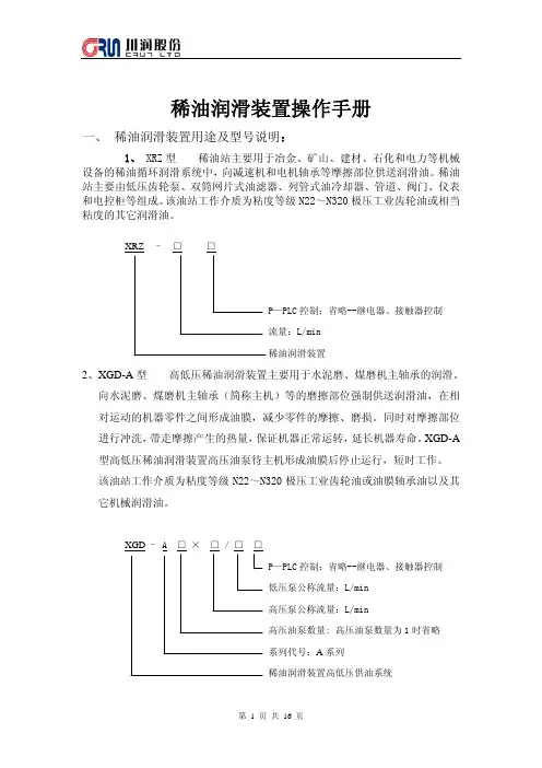

GDY系列稀油润滑装置说明书河南焦矿机器有些公司1、简介GDY系列稀油润滑油装置(以下简称稀油站)主要用于冶金、矿石、建材、石化和电力等机械设备的稀油循环润滑系统中,向球磨机静压轴承和静压启动面、减速机和电机轴承等(以下简称主机)摩擦部位供送润滑油。
稀油站主要由油箱、油泵、滤油器、油冷却器、管道、阀门、仪表和电控柜组成。
工作介质为N22-N460极压工业齿轮油或其它机械润滑油。
2、主要性能参数见表1:3、使用环境3.1海拔高度≤1000米3.2无振动、无腐蚀性气体、无爆炸的环境。
3.3环境温度0-40℃,相对湿度小于90%(25℃时)。
3.4供电电源50HZ、380V/220V,波动≤±10%。
3.5冷却水温度≤28℃、压力0.2-0.3MPa。
冷却器进口温度≤50℃.注:用户使用环境不符合时,应另签定《技术协议》做特殊订货。
4、工作原理与结构特点4.1油站的工作原理:稀油站工作时,油液由齿轮油泵从油箱吸出,经单向阀、双筒网片式油滤器、列管式冷却器或板式冷却器,被直接送到设备润滑点;同时向高压泵供油,低压油路的最高工作压力为0.4MPa,最低工作压力为0.2MPa,根据润滑点的要求,通过调节安全阀确定使用压力。
高压泵从低压油路上吸取油液,经直通单向阀进入主机中空轴润滑点,高压油路的工作压力一般不超过10MPa,最低工作压力不超过8MPa;当压力达到一定工作压力时主机被浮起,主机转动平稳后高压泵将延时停止工作,低压润滑系统工作,满足润滑点的需要。
当油站的工作压力超过安全阀的调整压力时,安全阀自动打开,多余的油液即流回油箱。
4.2稀油站的组成和结构特点:4.2.1油箱:油站上装有液位讯号器、油标、电接点双金属温度计双针压力表、压力变送器、压差开关铂热电阻和空气滤清器、排油排水阀,回油口装有磁性过滤装置等。
4.2.2低压两台油泵装置:一台工作,一台备用。
两台泵交替使用交替时间不应超过3天,以确保每台泵经常处于工作状态,一旦主泵出现故障时,备用泵能立即向主机供送润滑油,使供油无扰动。
XYZ系列稀油站说明书一、简介本装置主要适用于水泥、冶炼、轧制、矿山、能源、轻工、交通、运输、石化和电力等机械设备的稀油循环润滑系统中,向主机齿轮箱的齿轮和轴承等摩擦部位供送润滑油,起减摩擦和冷却润滑作用,保证供油和润滑质量,使主机设备连续正常运行。
其工作介质为N220~N320中负荷工业齿轮油或其它机械润滑油。
本装置由稀油润滑站,仪表盘,电控柜配套组成。
型号说明: 选型时采用XYZ- ※※P: PLC控制省略:继电器、接触器控制流量:L/min稀油站如:稀油站,公称流量125L/min,用PLC控制,则选型:XYZ-125P三、工作原理与结构特点稀油站由油箱、油泵装置、油冷却器、油滤器以及电控柜、仪表盘、管道、阀门等组成。
工作时,油液由齿轮泵从油箱吸出,经单向阀、双筒网片式油滤器、列管式油冷却器,被直接送到设备的润滑点进行润滑,然后经系统回油管流回油箱。
油站的最高工作压力为0.4MPa,最低工作压力为0.2MPa(视现场情况可重新设定),根据润滑点的要求,通过调节安全阀确定使用压力。
当油站的工作压力超过安全阀的调定压力时,安全阀将自动打开,多余的油液流回油箱。
稀油站具有过滤、冷却、加热等装置和安全、自控、报警等功能。
本稀油站有以下结构特点:1.设有备用油泵。
稀油站有两台油泵,一台工作,一台备用,正常情况下工作油泵运行,当系统压力低于压力调节器调定值时,备用泵投入运行,保证向主机继续供送润滑油。
2.采用双筒网片式油滤器。
双筒网片式油滤器有两组过滤滤芯。
一组滤芯工作,一组滤芯备用。
当工作滤芯需要更换时,可不停机,用转换阀使备用滤芯工作,即可取出原工作滤芯,更换滤片。
此油滤器结构紧凑,接管简单,不设旁路,更换方便。
3.采用GLCQ、GLLQ型列管式油冷却器。
换热管为紫铜管,冷却效果较好,体积小,重量轻,阻力降大大小于板式换热器,在工作压力本身不高的稀油润滑系统中使用是比较合理的。
4.回油口设有磁性过滤器。
1.用途XYZ200-L立式稀油站是北京电力设备总厂设计制造的,为ZGM95型磨煤机用SXJ140型立式螺伞-行星减速机配套的专用润滑装置,用于润滑减速机中的齿轮和轴承,起到润滑、冷却和清洗的作用。
2.工作原理稀油站在正常工作时,电机螺杆泵将润滑油从磨煤机减速机下箱内吸出,送入加热器,经管路进入双室过滤器的一个滤筒,再沿管路进入冷却器,然后被送到各个润滑点,润滑油经过润滑部位后汇集于减速机下箱,再经电机螺杆泵吸出,如此循环往复,使润滑油在系统中循环,确保系统各部位的正常润滑。
3.结构特点XYZ200-L立式稀油站由电机螺杆泵、电加热器、双室过滤器、冷却器以及阀门、管道、仪表和底座等组成。
所有零部件均安装在底座上组成整体式结构,稀油站无自带油箱,减速机下箱体就作为稀油站的油箱。
各部分的结构特征如下:3.1电机及三螺杆泵:立式,配双速电机,带安全阀。
驱动采用YD160M-8/4 V1型双速电动机,其功率为5.0/7.5kW,对应转速为720/1450 r/min。
若稀油站启动时油温<25℃时,先令电机720r/min运转,直到油温达到28℃时,再改用1450r/min运转。
油泵上装有对油泵和系统起过载保护作用的安全阀,阀的调节压力为0.63MPa,可保证安全运行。
3.2电加热器:带纵向折流。
纵向折流板将加热管分隔为三个区间,油和加热管间的相对流速增加,可避免因油流死角导致的油温过高区;加热管温度均衡减少了结炭现象;同时采用了能放尽空气的放气结构,保证油加热管温度最高的上部能浸入油液中;这些都提高了加热效率和延长了加热管的使用寿命,同时也减少了顶罩部分的温升,并且油液不易氧化变质,延长了油液的使用寿命。
3.3双室过滤器:采用纵向导流和上下磁过滤结构,带三位六通换向阀。
油液由换向阀进入过滤器中部后,由导向套引入下部,先均匀地经过下部磁过滤装置并由下而上均衡地通过滤网,再同样均衡地流过上部磁过滤装置,最后经换向阀进入下一个循环装置。
GDY系列稀油润滑装置说明书河南焦矿机器有些公司1、简介GDY系列稀油润滑油装置(以下简称稀油站)主要用于冶金、矿石、建材、石化和电力等机械设备的稀油循环润滑系统中,向球磨机静压轴承和静压启动面、减速机和电机轴承等(以下简称主机)摩擦部位供送润滑油。
稀油站主要由油箱、油泵、滤油器、油冷却器、管道、阀门、仪表和电控柜组成。
工作介质为N22-N460极压工业齿轮油或其它机械润滑油。
2、主要性能参数见表1:3、使用环境3.1海拔高度冬1000米3.2无振动、无腐蚀性气体、无爆炸的环境。
3.3环境温度0-40 C,相对湿度小于90% (25C 时)。
3.4 供电电源50HZ、380V/220V,波动W±10% 3.5冷却水温度冬28C、压力0.2-0.3MPa。
冷却器进口温度冬50 C .注:用户使用环境不符合时,应另签定《技术协议》做特殊订货。
4、工作原理与结构特点4.1油站的工作原理:稀油站工作时,油液由齿轮油泵从油箱吸出,经单向阀、双筒网片式油滤器、列管式冷却器或板式冷却器,被直接送到设备润滑点;同时向高压泵供油,低压油路的最高工作压力为0.4MPa,最低工作压力为0.2MPa,根据润滑点的要求,通过调节安全阀确定使用压力。
高压泵从低压油路上吸取油液,经直通单向阀进入主机中空轴润滑点,高压油路的工作压力一般不超过lOMPa最低工作压力不超过8MPa当压力达到一定工作压力时主机被浮起,主机转动平稳后高压泵将延时停止工作,低压润滑系统工作,满足润滑点的需要。
当油站的工作压力超过安全阀的调整压力时,安全阀自动打开,多余的油液即流回油箱。
4.2 稀油站的组成和结构特点:4.2.1 油箱:油站上装有液位讯号器、油标、电接点双金属温度计双针压力表、压力变送器、压差开关铂热电阻和空气滤清器、排油排水阀,回油口装有磁性过滤装置等。
4.2.2 低压两台油泵装置:一台工作,一台备用。
两台泵交替使用交替时间不应超过3 天,以确保每台泵经常处于工作状态,一旦主泵出现故障时,备用泵能立即向主机供送润滑油,使供油无扰动。
稀油站的操作规程一、油站的操作规程1、稀油站工作中,如因油压、油温和油位处于不正常位置时,则有相应的声光报警。
报警分为轻故障预报警用于提醒操作者注意,重故障报警用于强迫主机停机,除与集控连接外,一般还应与主机硬件连锁,报警时,可先按消音按钮,再根据故障诊断信号灯的显示,采取相应措施。
2、当过滤器压差高报警时,说明过滤已堵塞,应扳动油滤器的还向阀手柄,使用滤芯工作,取出原工作滤芯,更换或清洗滤片。
3、当出口油温大于42O时,应使冷却器投入工作,当油温小于42O时,根据主机工作情况可使用或不用冷却器。
二、维护和安全技术1、齿轮油泵使用与维护1.1、齿轮油泵头与电动机采用弹性连接,齿轮油泵中心线与电机中心线误差不得大于0.1mm,转动联轴器是否灵活。
1.2、油泵应尽量接近油箱,吸入高度不得大于500mm;1.3、油泵应牢固地加以固定,进出口管接头,不得有松动现象;1.4、为保证油泵长期使用,其抽送的油液必须清洁,不应有任何腐蚀物质和机械杂质;1.5、油泵使用时应安标牌所指示方向转动;1.6、安全阀应尽可能近油泵,根据需要进行调整;1.7、油封是易损件,如果主动轴出现漏油现象,应更换油封;1.8、油泵采用的时容积式泵,如果磨损或轴承损坏,泵的噪声增大,压力有所下降,应更换轴承。
1.9、检修齿轮后,重新装配时应严格控制泵的轴向间隙,同心度不能超差,否则不能正常工作。
1.10、齿轮泵严禁在周围环境温度过高(超过电机允许温度)的地方工作和露天工作,以免电动机受潮;1.11、停止工作时,先关闭电动机开关然后再关闭油管中的阀。
2、冷却器的使用与维护2.1、操作规程2.11、使用前检查所有附件与仪表,并查看各连接处是否紧固;2.12、将冷却器热侧排气阀打开,再缓缓开启冷进阀门(此时冷介质排出阀处于关闭状态),当冷介质充满后,关闭冷进阀门冷侧排气阀。
此时两种介质均成静止状态,经热交换后,温差逐渐减少;2.13、冷侧介质温升5-10O后,打开冷热介质的进出阀,使冷热介质均处于流动状态,然后调整两种介质流量,使温度达到工艺要求;2.14、冷却器因故或正常停止工作时,其操作步骤应按启动的逆过程进行;2.2、使用中的注意事项2.21、在开动冷却器时,切忌快速打开冷进阀门,因为冷介质大量流过冷却器时,会使热管表明形成一层导热性很差的“过冷层”,即使以后冷介质流量很大,也起不到良好的换热作用;2.22、如果冷介质为水,当发生电化腐蚀时,可以自行在水侧选择适当位置安装防电化腐蚀的锌棒;2.23、冷介质通常采用净化的淡水,为防止水垢形成,水的温度尽可能要低些,水流量要大些;2.3、维修、保养冷却器经过长期工作后,有腐蚀生成物、沉积物及水垢等附着于管壁,会降低传热系数,影响传热效率及增大压降,因此,视具体情况,及时清洗,以保证冷却器性能。
XYZ-6S125G稀油润滑站使用说明书启东市开隆冶金机械设备有限公司一设备的用途XYZ-6G- 125G型稀油站主要用于冶金、矿山、能源、建材、轻工、交通、运输等机械设备的稀油循环润滑系统中,向减速器、齿轮座、主电动机轴承等摩擦部位供送润滑油。
起减磨和冷却作用,确保主机设备连续正常运行。
本稀油润滑站使用工作介质粘度等级为N22〜N460的工业润滑油。
循环冷却采用列管式冷却器。
本油站通常是安装在主机附近或地下油库内、地坑内。
、设备性能参数三、工作原理及结构特点XYZ-G型稀油站主要由油箱、立式齿轮油泵装置、单向阀、安全阀、双筒网片式过滤器、列管式油冷却器、压力控制器、电接点双金属温度计、铂热电阻、仪表、管道及阀门等组成,并配套相应的电控系统。
XYZ-6G〜125G为整体式小型稀油站。
其外形详见设备外形图。
工作时,润滑油由齿轮泵从油箱吸出,经单向阀、双筒网片式过滤器、列管式油冷却器,被直接送到设备的润滑点。
油站的最高工作压力一般为0.4MPa,最低工作压力为O.IMPa。
油站的实际工作压力根据现场条件而定,关键是能否提供足够的流量。
根据润滑点的要求,通过调节安全阀确定使用压力,当油站的工作压力超过安全阀的调定压力时,安全阀将自动打开,油液即溢流回油箱。
安全阀的作用是当系统过载时溢流,卸压保护系统。
压力控制器用来检测系统的压力,铂热电阻用来检测润滑油温度。
油箱可储油和散热并分离油液中的气体及沉淀污物。
稀油站的结构有以下特点:1、设有备用油泵:稀油站有两台油泵装置,一台工作、一台备用,正常情况下工作油泵运行,当系统压力低于压力控制器调定值时,备用油泵投入工作。
确保向主机连续提供符合压力要求的润滑油。
2、双筒网片式油滤器放在列管式冷却器之前:油在油滤器中的通过能力与其粘度有关。
粘度大,通过能力差,反之通过能力好。
温度高,则粘度下降,通过能力好过滤的效果也较好,先过滤后冷却即达到此目的。
3、米用双筒网片式油滤器双筒网片式油滤器有两组过滤滤芯。
稀油站使用说明书河南省安阳力源液压有限责任公司一,用途稀油站主要用于冶金,矿山设备的稀油循环润滑系统中,向减速器,齿轮座,主电动机轴承等摩擦部位供送润滑油。
其工作介质可为透明油,20—50号机械油。
用于HJ3—28号轧钢机。
运动粘度范围20—326厘沲。
通常是安装在机器附近的地下油库内或地坑内。
二,规格与性能三,工作原理与结构特征XYZ型稀油站由油箱,油泵装置,过滤器,(双筒网式过滤器和磁过滤器)换热器以及电气,仪表控制装置,管道,阀门等组成。
稀油站工作原理:油液由齿轮泵从油箱中吸出,经单向阀,双筒网式过滤器,换热器,被直接送到设备的润滑点。
油站的最大工作压力0.4MPa,根据润滑点的要求通过调节安全阀确定使用压力,当油站的工作压力超过安全阀的调定压力时,安全阀将自动打开,多余的油液即流回油箱。
稀油站的结构有以下特点:1,设有备用油泵:稀油站有两台油泵,一台工作,一台备用,正常情况下,工作油泵运行,遇到意外,备用油泵投入工作,保证向主机继续供送润滑油。
2,过滤器放在换热器之前:油在过滤器中的通过能力与其粘度有关,粘度大,通过能力差,温度高,则粘度下降,通过能力好,过滤的效果也较好,先过滤后冷却即可达到此目的。
3,采用双筒网式过滤器:双筒网式过滤器有两个过滤筒,一筒工作一筒备用,当工作筒需清理时,用转换阀使备用筒工作,即可取出工作筒进行清洗。
机构紧凑,接管简单,不设旁路,清洗方便。
4,采用列管式换热器:冷却效果好,阻力小,便于维修。
5,回油口设有磁过滤器:可将回油中的细小铁磁物质吸附过滤,保证油的纯度。
6,配有仪表盘和电控箱:仪表盘上装有两块普通耐震压力表用来直接观察油泵及油站出口油压;两块电接点压力表实现油压自控。
一块电接点温度控制器观察并控制油温。
稀油站正常工作时,油泵一台工作,一台备用,有时设备耗油量由于某种原因需要增加时,则系统压力下降,当降到一定值时电接点压力表控制备用泵自动开启,与工作泵一起工作,直到压力恢复正常时,备用泵自动停止。