高温箱式炉操作说明
- 格式:docx
- 大小:13.55 KB
- 文档页数:1
高温节能箱式马弗炉使用详细说明烘炉:初次使用或长时间不用时,正式开炉前必须按要求进行烘炉,烘炉要求如下:室温~150℃保温一小时;150℃~300℃保温3小时;以免造成炉膛开裂,炉温不得超过额定温度,以免损坏加热元件及炉衬。
1.接通电源后(单项380V)先按炉子上的绿色电源键;2.按SET键(最左边的一个)显示OUT.(代表输出百分比)已调好;3.再按SET键显示AT(代表PID自鉴定,出厂时已调好)已调好;4.再按SET键显示PIN(代表程序组选择,一般选择第一段)已调好;5.再按SET键显示SEG(代表当前运行到程序第几组第几段)已调好;6.再按SET键显示TIOP(代表当前程序段还有多长时间)已调好;7.再按SET键显示SY—1(代表第一段的温度,可以用移位键和加减键调节所需要的温度);8.再按SET键显示TO—1(代表第一段的时间,就是说多长时间升到刚才SY—1所设的温度,可以用移位键和加减键调节所需要的温度。
注意:小数点的位置,小数点左边单位为小时,右边为分钟);9.再按SET键显示OUT—1(代表第一段输出百分比,一般都调为100.00,意思是百分比没有限制);10.再按SET键依次是SY—2、TO—2、OUT2(代表第二段程序设置),设置方法同第一段,第三段则改为3,依此类推直到第八段;11.如果现在设置到第五段,程序就会结束,那第六段的SY—2、TO—2、OUT2都必须清除为零,这样仪表才会自动终止。
(如果误进入到别的参数,请勿乱改,关掉电源,等待数秒钟再打开)再按红色加热键;12.关机。
仪表走到最后程序自动停止,再按以下红色停止键就可以了;13.一般自动程序结束后,仪表会自动终止。
如果在升温过程中想终止程序,按住减速键不放,马上再用另一只手按下设置键仪表下行显示0(代表仪表关机),放开。
注意事项:1.定期检查电炉,温度控制器导电系统各连接部分接触是否良好。
2.禁止向炉膛内直接灌注各种液体及溶解金属,经常清除炉膛内的铁屑、氧化物,以保持炉膛的清洁。
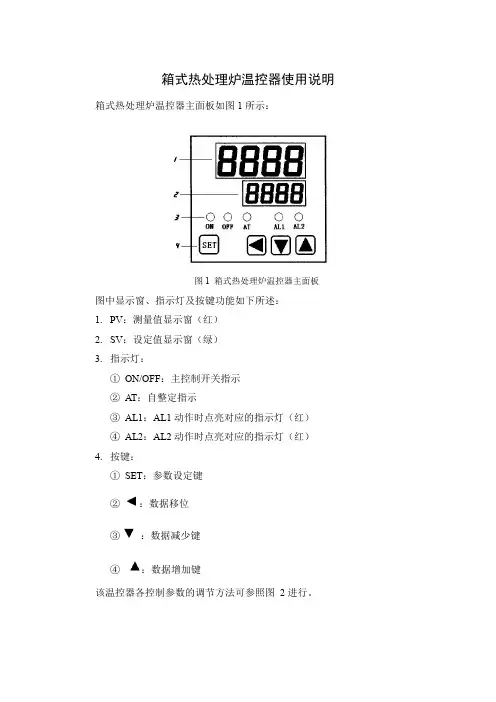
箱式热处理炉温控器使用说明箱式热处理炉温控器主面板如图1所示:
图1 箱式热处理炉温控器主面板
图中显示窗、指示灯及按键功能如下所述:
1.PV:测量值显示窗(红)
2.SV:设定值显示窗(绿)
3.指示灯:
①ON/OFF:主控制开关指示
②AT:自整定指示
③AL1:AL1动作时点亮对应的指示灯(红)
④AL2:AL2动作时点亮对应的指示灯(红)
4.按键:
①SET:参数设定键
②:数据移位
③:数据减少键
④:数据增加键
该温控器各控制参数的调节方法可参照图2进行。
按
图2 箱式热处理炉温控器参数调整流程图
另附各参数功能说明如下:
P:比例带。
该控制器的P参数引用国标上最常用的表示方法,即P代表比例带温区。
举例说明如下:若P设定为30℃,则原则上在SV±15℃的范围内进行PID控制。
当温度有规律波动时,应增加比例带,当温度无规律飘动时,应减少比例带。
P越大,调节作用越强。
I:积分时间常数。
当温度有规律波动时,应增加积分时间,当温度很长时间不能消除静差时,应减少积分时间。
I越大,调节作用越弱。
D:微分时间设定。
微分时间的增加有助于减少系统的超温。
但过大的微分时间将导致系统对微分时间过于敏感。
D越大,调节作用越强。
T:控制周期。
当系统的升降温速率较快时,应减少T。
一般来说,T越小,系统的控温效果越好。
但若主控为继电器输出,过小的T会影响继电器的使用
寿命。
高温箱式电阻炉[型号:SX-10-13]
一.操作规程:
1.使用前需要检查箱体及附件是否齐全,接线端子是否松动。
注意是否有断路或漏洞现象,
2.待一切准备就绪后就可将试样放入砂体,然后将砂体放入炉中,关上箱门。
3.通电使用:
a)确认接线无误后,接通总电源。
b)接通控制器电源开关此时根据工艺要求,按照仪表说明书设定使用温度,以及调整功率限幅
5.当曲线运行至降温曲线时闭炉,降温到300度以下时可以打开炉门将砂体取出二.注意事项:
1.当电炉第一次使用或长期停用后再次使用时,必须按照说明书进行一次烘炉干燥
2.保持炉膛内清洁,对炉内的金属氧化物,熔渣和杂质等应及时清除,装取砂体时应谨慎,以防碰坏碳棒
3.电炉和控制器必须在没有导电尘埃,爆炸性气体的条件下使用
4.不可在酸,碱,盐等腐蚀性,挥发性的气氛中使用
5.硅碳棒在使用时如果发现有的铝头发生腐蚀需更换。
箱式高温炉操作规程本文档旨在为操作人员提供箱式高温炉的操作规程,并确保操作安全和有效性。
请在使用前仔细阅读并遵守本规程。
1. 安全操作注意事项在进行箱式高温炉操作之前,请务必注意以下安全事项:•熟悉炉内温度和压力的设定范围,并且不得超出该范围。
•不要将可燃气体或易燃物品放置在附近。
•在执行任何操作之前,确保炉子已经冷却,并且将其断电并关闭。
•非专业人员不得擅自操作炉子。
2. 基本操作流程遵循以下步骤操作箱式高温炉:步骤1:准备工作•确保环境通风良好,并且无易燃气体泄漏。
•根据炉子的操作手册,检查并确认炉子的电源和气源的连接是否正常。
•将待加热的样品或物体置于合适的容器,以免对炉子和样品造成损害。
步骤2:设置参数•打开炉子的控制面板,按照操作手册中的说明设置所需温度和时间参数。
•在设置参数之前,确保了解样品或物体的热稳定性和热处理要求。
步骤3:启动炉子•按照炉子的操作手册,打开电源开关并将炉子预热至设定温度。
•确保炉子内部温度逐渐上升,不要突然升温,以免造成样品损坏。
步骤4:监控和记录•监控炉内的温度和其他重要参数,确保其在操作范围内。
•定期记录和记录炉子的温度和其他参数,以备后续参考。
步骤5:操作完成后的处理•在操作完成后,关闭炉子的电源,并将其冷却至安全温度。
•仔细取出样品或物体,避免烫伤,注意炉子内部可能仍然很热。
•清理和维护炉子,确保其在下次使用前处于理想的状态。
3. 紧急情况和事故处理如果出现炉子故障、温度过高或其他紧急情况,请立即采取以下步骤:•首先,关闭炉子电源,并将室温调低,以尽快降低温度。
•如果出现火灾,请立即通知消防队,并按照消防队的指示采取适当的灭火措施。
•如果出现炉子内有毒气体泄漏的情况,请确保自己和他人安全后,立即撤离并向有关部门报告。
•不要擅自拆卸或维修炉子,应该联系专业人员进行处理。
4. 维护和保养为确保箱式高温炉的正常运行和使用寿命,需要进行定期的维护和保养:•按照操作手册中的说明,定期清洁和检查炉子内部和外部的部件。
高温箱式炉操作高温箱式炉操作手册1. 简介高温箱式炉是一种常用的热处理设备,可用于高温烧结、高温退火、高温试验等工艺过程。
本操作手册旨在为使用者提供高温箱式炉的正确操作方法和注意事项。
2. 操作前的准备工作2.1 检查炉体使用前应检查炉体是否完好,包括外观是否有锈蚀、破损等情况;内部是否有杂物、灰尘等,需要及时清理。
2.2 校准温度控制器使用前应校准温度控制器,确保温度控制准确可靠。
2.3 选择合适的加热元件根据使用需求选择合适的加热元件,如电阻丝、石墨加热体等。
2.4 安装试样在操作前应根据需要安装试样,确保试样放置合理,以便于热处理过程的进行。
3. 操作步骤3.1 打开电源开关在操作前,先将电源开关打开,然后通过温度控制器设置所需温度。
3.2 加热过程将温度控制器设定为所需温度后,打开加热开关,高温箱式炉开始加热。
此时需观察温度升高的情况,确保温度上升平稳。
3.3 监测温度在加热过程中,需不断监测温度变化,并根据需要调整加热功率,以使温度保持在所需范围内。
3.4 热处理过程当温度达到设定值后,进入热处理过程。
此时需根据热处理工艺要求,进行保温、升温、降温等操作。
3.5 关闭加热设备当热处理过程结束后,需关闭加热设备,停止加热动作。
4. 注意事项4.1 安全操作在操作高温箱式炉时,需注意自身安全。
遵循安全操作规程,戴上防护手套、安全眼镜等防护装备。
4.2 温度监测在操作过程中,需不断监测温度变化,确保温度在安全范围内,避免温度过高导致设备损坏或事故发生。
4.3 加热功率在加热过程中,需根据温度变化及热处理工艺的需要,调整加热功率,保持温度的稳定和准确。
4.4 温度升降速度在进行热处理时,需注意温度的升降速度,过快或过慢都可能影响热处理效果。
需根据具体热处理工艺的要求,调整温度升降速度。
4.5 温度分布高温箱式炉内温度分布可能存在不均匀性,需在操作前注意试样放置位置,以保证温度分布的均匀性。
5. 维护保养5.1 定期清洁定期清洁高温箱式炉,包括炉体内外的清理,保持设备的整洁。
箱式高温电阻炉的使用方法以箱式高温电阻炉的使用方法为标题,本文将介绍箱式高温电阻炉的基本结构、操作步骤以及注意事项,帮助读者正确、安全地使用该设备。
一、箱式高温电阻炉的基本结构箱式高温电阻炉是一种用途广泛的实验室设备,主要由箱体、加热元件、温度控制系统和电源系统等组成。
箱体是炉子的外部壳体,通常由金属材料制成,具有良好的隔热性能。
加热元件一般采用电阻丝或电阻棒,通过电流通电发热,将箱体内的温度升高到所需的高温。
温度控制系统用于监测箱体内的温度并进行调节,常见的控制方式有PID控制和微电脑控制。
电源系统提供电能给加热元件,一般为交流电源。
二、箱式高温电阻炉的操作步骤1. 准备工作:将箱式高温电阻炉放置在稳定的工作台上,确保周围无易燃物品和易熔物品,保证通风良好;检查电源线是否接地良好,电源开关是否处于关闭状态。
2. 设定温度:打开温度控制系统的电源开关,进入温度设定界面。
根据实验需求,设定所需的高温数值,并确认设定。
3. 预热:按下预热按钮,启动箱式高温电阻炉进行预热。
预热时间根据设备型号和所需温度而定,通常需要数十分钟到数小时。
4. 放置样品:在预热过程中,准备待加热的样品。
根据实验要求,选择合适的样品托盘或容器,并将样品放置在托盘或容器中。
注意样品的尺寸和形状应适合箱式高温电阻炉的加热区域。
5. 加热:预热完成后,将样品托盘或容器放入箱式高温电阻炉的加热区域内,并关闭加热室的门。
启动加热程序,电阻炉开始提供热量,使样品温度逐渐升高。
6. 温度控制:在加热过程中,温度控制系统会实时监测箱体内的温度,并通过控制加热元件的电流来调节温度。
一旦温度接近设定值,温度控制系统会自动调整加热功率,保持温度稳定。
7. 实验操作:根据实验要求,在达到设定温度后进行相应的实验操作。
注意操作过程中应遵守实验室安全规范,佩戴好个人防护装备,避免发生意外。
8. 完成实验:实验完成后,关闭加热程序,待箱式高温电阻炉冷却到安全温度后,打开加热室的门,取出样品。
箱式电炉操作规程
一、操作方法:
接通电源,打开控制器电源开关,将温度调节仪表设定至所需温度,此时仪表路灯亮,表示加热开始。
当温度升到设定温度时,调节仪表自动切断电源,红灯亮,电流表指示归“零”, 即表示加温停止。
此后调节仪表的“红”、“绿”指示灯交替工作,从而使仪器达到恒温状态。
二、注意事项:
1、当电炉第一次使用或长期停用后再次使用时,必须进行烘炉,烘炉时间室温-200℃, 打开炉门4小时,200℃-400℃,关闭炉门两小时, 400-600℃关闭炉门两小时,使用时,炉温不得超过最高温度,以免烧坏电热元件,并禁止向炉膛内灌注各种液体及易熔解的金属。
2、电炉和控制器必须在相对湿度不超过85%, 没有导电尘埃或爆炸气体和腐性气体的场所工作。
3、控制器的工作环境温度限于 5-50℃
4、热电偶不要在高温骤然拨出或插入,以防外套管炸裂。
5、经常保持炉膛清洁, 及时清除内氧化物之类的东西。
6、试验完后切断电源。
箱式加热炉操作方法
箱式加热炉是一种常见的加热设备,用于加热物体或材料。
以下是箱式加热炉的操作方法:
1. 准备工作:确保加热炉周围没有任何易燃或易爆物品,并确保通风系统正常运转。
2. 载入物体或材料:打开加热炉的门,将要加热的物体或材料小心地放入加热炉内。
注意不要超过加热炉的最大容量。
3. 设定加热温度:根据加热炉的使用要求,设定所需的加热温度。
可以通过加热炉上的温度控制面板或按钮来调节温度。
4. 启动加热炉:打开加热炉的电源开关或燃气开关,开始加热过程。
加热炉会开始升温,直到达到设定的加热温度为止。
5. 加热过程中的监控:在加热过程中,定期检查加热炉的温度显示器,确保温度保持在设定范围内。
同时,注意观察加热炉内部的情况,确保不发生任何异常。
6. 关闭加热炉:当加热过程完成后,将温度设定回室温,并关闭加热炉的电源开关或燃气开关。
7. 取出物体或材料:等待加热炉冷却至安全温度后,打开加热炉的门,小心地取出已加热的物体或材料。
8. 清洁与维护:定期清洁加热炉的内部和外部,以保持其良好的工作状态。
如有需要,及时更换加热炉的加热元件或其他配件。
注意事项:
- 在操作加热炉时,要遵循安全操作规程,避免人身伤害或火灾等意外发生。
- 根据不同的加热炉型号和加热需求,可能会有一些特殊的操作要求,请参考具体的操作手册或使用说明。
高温箱式炉操作方法
操作高温箱式炉的方法如下:
1. 开机准备:确保高温箱式炉的电源和燃气供应都正常,并检查炉内是否有任何易燃或易爆物品。
2. 设定温度:根据需要的温度,使用控制面板上的调节按钮或旋钮,将高温箱式炉温度设定为所需的温度。
3. 预热炉内:打开高温箱式炉门,将待加热物品放入炉内,并将炉门关闭。
然后按下预热按钮,开始预热炉子。
此时,炉子会自动点火并开始升温。
根据炉子的规格和温度需要,预热时间会有所不同。
等待炉子达到设定温度。
4. 加热:当高温箱式炉达到设定温度后,可以按下加热按钮,使炉子继续保持设定温度。
此时,炉子会根据设定温度自动控制加热器或燃气阀门的开启和关闭,以维持稳定的温度。
5. 炉内操作:根据需要,可以根据工艺要求进一步调整温度或其他参数。
有些高温箱式炉可以连接到计算机或控制系统,通过外部设备进行远程监控和控制。
6. 关机:使用完高温箱式炉后,按下关机按钮或将温度调节到较低的数值。
然后关闭炉子的电源和燃气供应。
注意事项:
- 在操作高温箱式炉过程中,要保持注意安全,避免烫伤或其他意外。
- 不要打开或触摸高温箱式炉的热表面,以免烫伤。
- 在操作高温箱式炉时,要根据使用说明书和厂家建议进行操作,以确保操作正确和安全。
箱式高温电阻炉的使用方法箱式高温电阻炉是一种广泛应用于实验室、工厂和医药领域的设备,主要用于各种物质的热处理、加热和实验。
下面将详细介绍箱式高温电阻炉的使用方法。
首先,使用箱式高温电阻炉前需要确保炉内的工作环境清洁卫生,无杂物和水汽。
同时,检查电炉内温控器、电器元件是否损坏,电源是否正常连接。
然后,接通电源并启动开关。
在启动后,拧动温度调节旋钮选择所需加热温度,通常箱式高温电阻炉可以达到800摄氏度以上。
在加热过程中,箱式高温电阻炉会发出噪音和微弱的烟雾味,这是正常现象,请不必担心。
炉内的加热元件会产生一定的热量,因此在使用过程中需要注意安全,避免触摸炉体和炉门。
同时,为了保证炉内的空气流通,防止温度过高,必要时可以打开通风口。
当箱式高温电阻炉达到预定的加热温度后,一般会采用自动恒温控制,以保持温度的稳定。
温度控制器一般具备温度调节和温度显示两个部分。
操作时,首先按下温度调节键,然后通过加减键分别增加或减少所需温度。
调节好温度后,再次按下温度调节键即可确定设定温度。
温度显示部分可实时显示当前的炉内温度,方便使用者掌握情况。
在使用过程中,一定要遵守操作规程和操作指南,不可随意调整温度和操作方式。
在打开炉门时,要注意热气的排放,避免烧伤。
当需要取出加热物品时,应使用工具或防烫手套,切勿直接用手触摸,以免烫伤。
使用箱式高温电阻炉后需要注意以下几点:1. 使用完毕后,应及时关闭电源,并等待炉体完全冷却后清洁炉腔,可用软布或刷子轻轻刷除残渣和灰尘。
2. 如果长时间不使用,建议将电阻炉放在干燥通风处,避免潮湿和灰尘的侵入,以免影响使用寿命。
3. 定期检查温控器、电器元件和加热元件,如有损坏应及时更换。
4. 当发现故障时,应立即停止使用,并寻求专业维修人员的帮助,切勿私自拆卸维修。
总结箱式高温电阻炉的使用方法,主要包括启动电源,选择温度,注意安全,加热、恒温控制,及日常维护等几个方面。
正确的使用箱式高温电阻炉,不仅能有效提高工作效率,保证实验的准确性,还能延长设备的使用寿命。
箱式电炉使用说明及操作规程一、安装环境要求箱式电炉安装前,需注意以下环境要求:1、安装地面要平稳坚固,距离墙壁应有足够的空间。
2、选择通风良好的场所,以确保使用时的通风降温。
3、尽量避免电炉周围存在可燃物。
4、避免日照直射和雨淋直接影响电炉。
二、使用前准备箱式电炉安装后,需要进行以下使用前准备:1、打开电炉盖,检查电炉内部是否有杂物。
2、检查电炉中的电线和控制器是否齐全,接线是否牢固。
3、电源线选择至少符合额定电压和电流的电线,并且要安装保险。
4、加热体的安装和连接要正确无误。
5、通电前确认所有部件的连接无误,并且确认电炉内部无人。
6、启动前请检查温度控制器是否有漏电或异味,确认无问题后再通电。
三、操作规程1、开机前确认通电正确,按照使用说明书合理设置电炉参数。
2、开机后,可以调整电炉的工作参数,包括加热时间、温度范围等。
3、加热时间要根据物料的特点和加工需求进行调整。
4、加热过程中请注意观察电炉内部温度的变化,及时调整参数,确保物料热处理质量。
5、加工结束后,请先将电炉降温至室温,再关闭电源。
6、每次使用完毕后,请及时清理电炉内部的杂物,以确保下次使用时的卫生和安全。
四、注意事项1、启动电炉前应仔细阅读使用说明书,确保操作正确无误。
2、电炉使用过程中,请勿随意拆卸、更改电路和控制器。
3、停机后应清理电炉内部的杂物,保持电炉干净卫生。
4、避免电炉过度使用,确保电炉使用寿命。
5、每年应进行一次维护保养,更换电炉内部的加热元件。
6、在电炉工作时应注意安全,避免人员伤害和火灾。
7、使用时应注意防潮、防虫、防尘和防霉。
KSL-1100X High Temperature MuffleFurnaceOperation Manua lMTI Corporation860 South 19th Street, Richmond, CA 94804, USATel: 510-525-3070 Fax: 510-525-4705E-mail: ***************Web site:ContentProduct Introduction (3)Technical Specifications (3)Furnace Structure (3)Operating environment (4)Instrument features (4)Operation (4)Power Connection (4)Thermocouple Installation (5)General Operation (5)Temperature Controller Instruction (6)Temperature Controller Setting (6)Temperature Segment Setting example (7)Illustration of Temperature Segment Setting (8)Run the program (9)Temperature Controller Parameters (10)Introduction (10)Parameter Function (10)Parameter Setting (11)Introduction of Default Parameters in the controller (12)Troubleshooting for typical Problems (13)Troubleshooting resources (13)Quick Troubleshooting (14)Maintenance and Caution (14)Knowledge on AC Power Connection (15)Typical Two Phases AC Power in US (16)Thanks for purchasing MTI’s product, please carefully read this manual beforeProduct Introduction●Applications: 1. Gravimetric analysis2.Sintering3.Quantitative analysis4.Heat treating5.Glass preparation●with thermal-efficient alumina fiber ceramic insulation;●Three sides resistance wire coil for fast and uniform heating;●Heavy duty double layer structure with cooling fan ensure the lowertemperature at outside case;●0.5" diameter quartz glass observation window allows user to see insidechamber during heating operation (Optional gas filling port can be added viathe window);●The observation window can be used as gas inlet by inserting an Aluminatube;●K type thermocouple installed for immediate use;●Precision temperature controller can provide 30 segments heating and cooling stepswith accuracy at +/- 1 oC;●Vent port installed on the top for gas flow (gas outlet);Note: For more information of optional product accessories, please search by keyword “EQ-KSL1100X” on Technical SpecificationsFurnace StructureOperating environmentThe operating environment information in the following table may be helpful if you plan to safely operate the instrument:⏹The construction request a dry, hard and flat surface;⏹The instrument shall be kept indoor with nice ventilation and avoided directsunlight;⏹Operating temperature: 500C~3500C;⏹Relative humidity (noncondensing): 10%~85%;⏹Dust-free.WARNING: To reduce the possibility of heat-related injuries or of overheating the instrument, do not place the instrument too close to the side wall or obstruct the air vents. Keep the instrument at least 1 meter in distance from the side wall.Instrument features●Power:3500W;●Operating V oltage: 220V AC±10 Single Phase 50/60 Hz;●304 stainless steel chamber;●Operation Temperature Range: 100~11000C;●Maximum Temperature: 1200 0C(The maximum temperature should not be holdmore than an hour);●Stability at 1000 0C: +/- 0.5 0C;●Uniformity at 1000 0C: +/- 2.0 0C;●Suggested Normal Heating Rate: ≤ 400C /min;●Max. Heating Rate: 50 0C /min;●Temperature control: 30 segments programmable digital controller with PIDfunction and overheated and overloaded protection;●Chamber Cubic Capacity: 438 cubic inch , 7.2 Liter;●Shipping weight (lb): 110 Lbs;●Overall Dimensions D x H x W (Inch): 25”x 21”x 27”;●Warranty: One Year limited.OperationOnce you received MTI furnace, please follow these steps to set up the furnace.●Open the box; check out if the instruments and the accessories are well keptduring the shipping and corresponded with the packing list, if not, please informus at ***************.●The instrument shall be kept indoor with nice ventilation;Power ConnectionThe furnace uses single phase AC 220V / 3.5 KW power. Please make sure that power source in your lab is enough to meet this power requirement. The following picture is to show you the three wires, Ground, Live 1, Live 2. We strongly suggest you contact aThermocouple InstallationActually, we have ready well installed the thermocouple before shipping, if there is a must to reinstall the thermocouple, please refer to the following steps.● Insert thermal couple tube (ceramic tube) in to furnace from backside of furnace,then tighten screw to fix thermal couple‟s position.● Connect thermal couple wires to controller. Please make sure that positive andnegative polarities are connected correctly (Red to positive; Black to negative;otherwise, controller can not work).General Operation● Place the test sample inside the Chamber (Crucible may be used as materialcontainer, please visit: /ceramiccrucibles.aspx ), slightly close the front door.● Properly connect to the power supply and make sure it is well grounded;● Power on the instrument by pressing “Run ” button and you will see the controlpanel start to blink.● Please refer to the following part “Temperature Controller Instruction ” forhow to set the temperature curve.NOTE :Once you finish the set up, we strongly recommend our customer FIRSTLY reading the handbook and then following the instructions of attached “QUICK TEST ”inside the package to perform a quick test to check the heating condition of the furnace.CAUTION: To reduce the risk of electric shock or damage to your instrumentduring your quick test, observe these practices:⏹ The outer plate of the instrument must be grounded properly, for safety ofoperation;Temperature Controller Instruction708P Temperature Controller 1. Specificationa. Compatible Thermocouple: K 、S 、R 、E 、J 、T 、N;b. Measurement Accuracy: 0.3;c. Power Input: Single phase 220V AC (±10%) / 50~60Hz;d. Power: ≤5W;f. 30 Programmable Segments.2. StructureMTI have three kinds of temperature controllers but with the same function as below:Here we take the first one as default to describe the operation:Temperature Controller SettingStartup stateWhen start the device, the meter type and program version will display for a few seconds, and then enter the normal state. Blinking “stop” indicates the program is in stop state.Displaying switcha. In the “no rmal stat e” or “p rogram running stat e”, press “SET” keyfor 1 second to switch to “executing program segment” (Setexecuting segment or display the ongoing temperature segment).b. Press “SET” key again for 1second to switch to “running time state”(Display the total running time PV xxxx min. and the elapsed time SV xxxxmin.)c. Press “SET” key again for 1 second to back to “normal state”. Temperature Segment Setting exampl eLTDE programmable smart instrumentation auto-controller allows you to set the temperature profile up to 30 segments. To process this function, follow these steps:●Power on the furnace, blinking “STOP” on the SV window indicates the NormalState;●Press “←” once to display “C01” on PV window;●Set initial temperature to 0 o C by using Keystroke s :“←”, “↑” or “↓”;●Press “Set” to display “t01” on PV window;Keystrokes :“←”, “↑” or “↓”;●Press “Set” to display “C02” on PV window; Set the actual working temperature forthe second segment by using Keystrokes :“←”, “↑” or “↓”;●Press “Set” to display “t02” on PV window; Set heat-up time from initialtemperature to target temperature by u sing Keystrokes :“←”, “↑” or “↓”;●By pressing “Set”, you can get into the following segments(C03&t03;C04&t04;C05&t05…) for temperature and time setting;●Press “Set” to display “Cxx” on PV window (xx could be any values among 01~30);●Press“←”, “↑” or “↓” to set “-121” in the last segment in order to shut down thefurnace;Illustration of Temperature Segment SettingSetting Example: Temperature Control Program with 6-segmentsFigure IAccording to figure I above, all segments was recorded in the following:Prompt Input Data DescriptionRun the program●When temperature program set up ready, wait until “STOP” shows on SV windowagain, then press “↓”and hold for two seconds to display “Run” on SV window;●Furnace will run automatically segment by segment according to the programsetting;●PV window displays increasing temperature at this moment;●If you need to hold the furnace at certain temperature when the program is running,press “↓” for 2 sec to hold the program and again press it to continue.●You can stop the program either from running or hold state by pressing “↑” for 2seconds.Attention:⏹When finish all the segments you need, please end the last segment with -121;⏹It is not suggested to modify any parameters during the execution if he or she isnot familiar with the furnace operation. If there is a must, please first stop theprogram.Temperature Controller ParametersIntroductionNote: Whenever you want to change the parameters that referred below, please firstly change the value of parameter “Loc” to “808” in order to unlock the parameter settings.Parameter FunctionMaintain parameter M5:Like integral time of PID calibration, this parameter is mainly in charge of the integral work during the adjustment process, for instance, the smaller the M5 is set, the stronger the system integral effect is, vice versa. When M5=0, the system will cancel integral and intelligent adjustment, leave only proportion and differential (PD) function.Speed parameter P:Parameter p has nothing to do with integral function. The bigger the p is, the stronger the proportion and differential function are, vice versa.Delay time t:It is defined as the time spent when the heating rate reaches to 63.5% of the maximum value with assumption that there is no heat dissipation. Remember, this parameter affects the three functions such as integral, proportion and differential, the smaller t is, the stronger proportion and integral function are but weaker differential, after all, the system feedback is promoted, vice versa. If t≤1, the differential function will be off.Control type CtrL:(Do follow the default setting, or the system may be unable to work)When CtrL=2, startup auto-tune function, after that, system will go to 3.When CtrL=3, adopts advanced AI adjustment, after auto-tune, the system goes to this setting mode, note that in this mode, you can not startup auto-tune function from the panel by holding button, for a protection of repeating auto-tune.Parameters lock LOC:Please set LOC “808” in order to unlock the parameters setting. Otherwise, please keep it as default “0”.Parameter Setting●In the “normal state”, press“SET”key for 2 seconds, you will see parameter “M5”pops up and press “←”, “↑” or “↓” to modify the parameter.●P ress “SET” key for 1 second to go to next parameter and press “←” for 2 seconds toback to preceding parameter.●Press “←”and then press “SET”key to back up to “normal state”. Without anyoperation on the keys for about 30 minutes, the meter will automatically exit from “parameter setting state”.Introduction of Default Parameters in the controllerAuto-tuneIn order to get a precise temperature control, customer should pay more attention to the parameters of M5, P and t. Actually, MTI‟s engineers have already mad e a strict high temperature pre-heating test (rate: 5℃/min) and fixed on these three parameters according to each furnace‟ condition before shipping it out. Therefore, we have a confidence of satisfying over 95% customers.However, the diversity of environment and the distinction in manufacturing for each customer, may seriously affect the operation, so, using auto-tune function to decide these parameters for a perfect result when the temperature is not stable and the error is large:●Run the program and wait until the furnace temperature reaches to 80% of your desiredtemperature.●Set the control parameter …CtrL‟ as 2 and then press “←” then “SET” key to switchback to …Running State‟.●You will see the meter flashes with “AT”, it indicates the meter has been in the“auto-tune state”. Then, system begins to oscillate 2-3 times and the meter automatically analyzes the furnace‟ temperatu re controlling period, amplitude, wave type and coefficient of heat preservation at current temperature segment, finally, yields the three parameters as M5, P and t. Press “←” for 2 seconds to force the meter to stop flashing at any time you want.●Due to d ifferent temperature, the time spent for “auto-tune” may be distinct.Note: that the parameter …CtrL‟ will be set as 3 by the system after “auto-tune”, so, if customer need more “auto-tune” operation for the furnace please reset the …CtrL‟ to 2.*Actu ally, “auto-tune” function could produce exact parameters for a general use. For the advanced customer who is familiar with PLC and pursuing perfect accuracy, they can manually modify M5, P and t in terms of experience, MTI would be glad to provide useful information as following:Please draw the system response plot, if it is:◆Short oscillating period, you can decrease P (priority), increase M5 and t.◆Long oscillating period, you can increase P (priority) as well as M5 and t.◆No oscillating but offset is large, decrease M5 (priority), increase P.◆Stable controlling but time-consume is too long, decrease t (priority) as wellas M5, increase P.Increase (or decrease) one of the three parameters by 30%-50%, if the controlling becomes better, continue increasing (or deceasing), otherwise, decrease (or increase) it till get the qualified adjustment. Commonly, M5 posses a priority, if not enough, try P and t.Troubleshooting for typical ProblemsTroubleshooting resources⏹Visit MTI web site link: for additional information aboutthe instrument through Help and Support;⏹Contact us by tel: 510-525-3070 or email: ***************.Quick TroubleshootingThe furnace is unable to start upIf the furnace can not turn on when you press the power button:⏹Be sure the furnace is plugged into and AC outlet with adequate power;⏹Fuse in controlling circuit might failure. Check the control circuit and replace thefuse.The temperature inside the chamber can’t go up⏹Temperature may be set too low, adjust the setting value of temperature;⏹Thermocouple may be failure, check and replace the thermocouple;⏹Temperature controller may be broken, check and replace the thermocouple; Real temperature inside the chamber does not match the setting value⏹Temperature sensor may be broken, replace the temperature sensor/thermocouple; Overheated protection alarm⏹Cool furnace down, and find reason why temperature is so high (program settingmay be wrong);SV show “OraL” alternately⏹Thermocouple has open circuit, inspect thermocouple;SV show “HIAL” alternately⏹Furnace temperature is over upper limit, Please let the furnace naturally coolingdown and then check out the reason of over-heating.Maintenance and Caution●In order to prevent the furnace module from splitting, the furnace shall be used afterbeing heated for 1 hour at 120 o C and 2 hours at 300 o C if you firstly apply it or have left it aside for long. Never keep the furnace temperature over rated temperature for avoiding damage on heating element or cover. Do not pour any liquid or melting metal into the module to keep clean inside.●Set a medium heating rate and small temperature difference between adjacentsegments when the furnace is cool. Please make a considerate setting on the heating rate in terms of the character of material sintered.●Regular check the wire connection and link junction of the heating element.●Please refer to parameter “M5, P and t” set ting if the temperature offset can not beeliminated and the difference between PV and SV goes far at 300 o C.●Working environment⏹Circumstance temperature: -10~75 o C.⏹Relative humidity:85%⏹Keep from electric dust, explosive and corrosive gas;⏹Keep stable position when working.●MTI‟ furnace (not including tube and heating element) has one year warranty since itis shipped out. We will give you free maintenance if there is a quality problem. For any misuse and damage, we will make a charge according to the damage condition if there is a requirement of mending.Notice: MTI never suggest you put any noxious, explosive or flammable gas into the tube.Knowledge on AC Power ConnectionFor power connection, you must follow your local law and let a licensed electrician do it. MTI Corporation is not responsible for any damage caused by wrong power connection.Extra power connection knowledge is not only for you to get a better application of the product, but also for your safety.If your country uses 220V power, you have no problem.If your country uses 110V power, you may need a 208~240V single phase AC power line.Ask your electrician to make single phase 240V power line, similar to you set up a 240V electric washer/dryer in your home. Please prepare the following knowledge:Three phases (240V) AC power panel box usually is located in the laboratory and inside wires are shown below.In order to get single phase 240V , two power lines come from two live wires, Of course, a 240V switch breaker must be installed.Typical Three Phases AC Power in USSignal Phase 240v from two live wires Signal Phase 110v from one live wire and neutral wireTypical Two Phases AC Power in USConnect the power cable of the furnace to a male plug and the two single phase wires to female and then connect them for easy and safe use:Again, the above information is just for basic knowledge only; please contract a licensed electrician to do the connectionPower Breaker110 AC from one neutral and one live wire240 AC from two live wires Ground Live 1 Live 2。
箱式电炉操作规程箱式电炉是一种广泛应用于工业生产领域的加热设备,其操作规程十分重要。
下面是一个关于箱式电炉操作规程的示例,供参考:1.设备检查1.1操作人员应在使用箱式电炉前,先检查设备是否完好,有没有损坏或松动的部件。
1.2检查并确保设备的电源及线路连接正常、可靠。
1.3检查箱式电炉的控制面板是否显示正常,各种仪表是否工作正常。
2.加热操作2.1打开电炉的电源开关。
2.2调整箱式电炉的温度控制器,将温度设定值调至所需的加热温度。
确保设定值与实际要求温度相符。
2.3启动箱式电炉的加热电源,控制加热功率,使箱式电炉开始加热。
2.4定时检查箱式电炉的工作状态,确保温度控制正常,以防止温度过高或过低。
2.5如有需要,可以根据实际情况进行温度的微调,以保证加热的稳定性和准确性。
3.加热结束3.1当加热时间到达预定时间或加热任务完成后,关闭箱式电炉的加热电源开关。
3.2等待箱式电炉冷却到安全温度后,可以打开箱门。
3.3注意,开关箱门时,要确保周围环境的清洁,防止灰尘或其他杂质进入箱式电炉内。
4.清洁和维护4.1在操作结束后,关闭箱式电炉的电源开关。
4.2清洁箱式电炉的外壳,防止积尘影响设备的正常使用。
4.3定期检查和清理加热元件,确保其表面清洁,不受到任何污垢的影响。
4.4如发现设备有任何故障或异常状况,应立即停止使用,并进行维修或更换相关零部件。
5.安全注意事项5.1操作人员在使用箱式电炉时,要穿戴好符合要求的劳动保护用品,如防护眼镜、手套、面罩等。
5.2操作人员不得单独留守操作箱式电炉,必须由专人负责并在附近监视。
5.3使用箱式电炉时,注意防止电炉和加热元件的烫伤,避免直接接触加热部件。
5.4箱式电炉使用过程中,应随时保持设备周围的环境整洁,防止杂质进入设备内部。
通过遵守以上箱式电炉的操作规程,可以保证电炉的正常运行和安全使用,提高生产效率和加热质量。
高温箱式电阻炉作业指导书
一、适用范围:
本系列电阻炉可供试验室、工矿企业、科研单位等作元素分析测定,小型刚件及其它金属件热处理时加热用。
二、使用前应做的准备和应具备的条件:
1.环境条件要求:
1.1试验室温度最好在低于最高温度50℃以下工作,相对湿度不大于85%。
1.2 电阻炉应放在平整的地面或搁架上。
1.3 应装设专用供电设备和良好地线。
2. 人员要求:
2.1 试验人员应充分了解该仪器的性能。
2.2 首次使用,必须经培训合格后,方可使用。
3. 设备状态:
试验前检查设备唯一状态。
(设备仪器只有在“合格使用”状态下才能使用)
三、操作步骤:
1. 把TDW系列温度控制仪的旋扭调到所需的温度数值上。
2. 接通电源开关,电源指示灯和ON灯亮。
3. 顺时针方向拧动粗调旋钮,同时观察电流与电压表的指示值,使输出功率(电流与电压乘积)略低于电炉的额定功率。
4. 顺时针方向拧动细调旋钮,使输出功率(电流与电压乘积)达到电炉的额定功率。
5. 当电炉的温度升高到需要值后,可相应调小输出功率,以便炉温比较稳定。
高温箱式电阻炉操作规程
1 确认炉膛无试样等异物,并检查耐火砖是否完好(耐火砖尺寸
172x115x30mm,并倒15°斜角)。
2 开总闸,控制柜上选择电流加载方式为“自动”(默认),确定“自动调节”旋钮为最小状态,电源开关打向“通”。
3 设定加热温度和报警温度:将温控开关打向“控温”,缓慢调节“控温设定”旋钮至所需温度;将温控开关打向“报警”,缓慢调节“报警设定”旋钮至所需温度;最后,将温控开关打向“测温”,显示当前炉温。
最高常用温度为1100℃,超过此温度,需特别申请。
4 电流调节采用多段电流控制升温:室温至80℃,调节“自动调节”旋钮至电流表示数不超过60A;80~120℃时,调节“自动调节”至电流表示数不超过80A;120℃至所需温度,调节“自动调节”旋钮至电流表示数100A。
超过800℃时,电流可稍许加大一点,但最大电流不超过110A。
夏天开始升温电流可调至70A。
炉温达到或接近设定温度时,电流会不停的浮动以稳定炉温。
建议,将电流调小以减少控制柜发出的噪声。
5 放取试样:炉温达到设定温度并稳定一段时间后,将电流调至最小,打开炉门,移走耐火砖,将试样平稳的放至炉膛中心处,移回耐火砖,并关上炉门,将电流调回100A左右。
取样时,也必须将电流调至最小。
总之,先关电流,再放取试样;快放快取,耐火砖不离开炉膛。
6 试验结束后,确认电流为最小状态,将电源开关打向“断”,关总闸。