pH-M400简要操作说明(0706)
- 格式:doc
- 大小:86.50 KB
- 文档页数:3
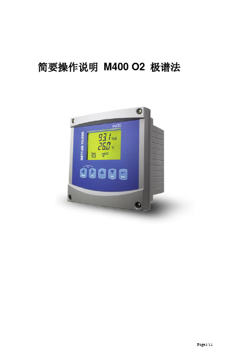
简要操作说明M400 O2 极谱法M400 O2 极谱法简要操作说明关键词:M400 氧极谱法压力补偿校正分辨率摘要:M400系列变送器接测量pH、溶氧电极时时有些参数必需确认/设定才能正常使用,下面介绍关于M400系列变送器的使用极谱氧电极常用参数设置。
目录1.仪表功能 (3)2.接线端子分部功能 (3)2.1. 1/2 DIN (3)3.接线图 (4)3.1. TB3接口---传统(模拟)氧传感器 (4)3.2. TB4接口--智能(ISM) 氧传感器 (4)注意: (4)M400使用有源4-20mA模拟输出。
请勿向TB2 1~6号引脚供电。
(4)4.电极类型选择 (5)5.模拟输出(4-20mA)设定 (6)6.显示分辨率设定 (7)7.溶氧压力补偿设定 (8)8.溶氧校正 (9)9.报警信息查看和处理 (9)10.测量原始数据查看 (10)11.附录1:安调步骤 (11)1. 仪表功能M400系列变送器不同型号功能不一样,安装使用时需根据具体型号了解其具体功能。
注:*未上市; **气相、液相2. 接线端子分部功能2.1.3. 接线图注意:M400使用有源4-20mA模拟输出。
请勿向TB2 1~6号引脚供电。
4. 电极类型选择路径:Menu →Quick Setup →Channel Select 。
红色是可修改部分在测量状态按进入快速设定菜单按选择=ISM 或AnalogO2 Hi 对应InPro6800系列; O2 Low 对应InPro6900系列按进入下一页,a 表示测量界面显示的行数%Sat 此行需要显示的测量参数选择Yes 可进行模拟输出(4-20)1进行设定按进入下一页,Min 和Max 分别对应4mA 和20mA 的值 如需设更多输出,参见第5节按进入下一页,选择Yes 可进行报警触点设定,Off 处可修改成Low ,High 等按进入下一页,选择Off 无此界面。
例如,选择Low 可进报警数值设定按进入下一页,选择需要使用的继电器号。

M400-pH简要操作说明1. 功能说明和接线1.1. 功能说明M300-pH用于测量pH值,其操作模式包括三个部分:测量、校准和参数设置。
在设置模式中按“Menu”键可回到测量模式。
1.1.1. 测量模式用于正常运行时仪器进行pH的测量。
1.1.2. 校准模式(Cal)用于pH电极。
在显示屏的上方显示(校准)图标。
1.1.3. 设置模式(Conf)用于调整仪器的运行参数(参见3)。
进入的的步骤为:在测量模式下按enter键,用 和 键输入密码1200,按“Enter”键进入设置模式。
1.2. 端子说明TB1:继电器输出TB2:模拟量输出/数字输入TB3:传感器输入接口1.3. 电缆接线:端子号VP电缆AS/AK电缆1(pH电极)透明线(玻璃电极)同心电缆内芯(玻璃电极)3(参比电极)红线(或屏蔽线)通信电缆屏蔽线4 黄绿线/蓝6(Pt100/1000)白线8(Pt100/1000)绿线注:在电极在无溶液接地时要将端子3和4跨接(短路)在电极温度传感器有线电阻补偿时需将灰线接到变送器接口TB3的第7端子。
2. 校准模式2.1. 进入校准模式:进入校准模式的步骤为:在测量模式下按“Cal”键,用 和 键选择所需的校正模式(1point(一点校正);2point(两点校正);process(过程校正)),按“Enter”键确定(我们一般都选择2point)。
校准步骤:在校准模式下,将干净2.2. 查看校准参数:在测量模式下按“Cal”键,不输入密码,直接按“Enter”键,可查看最近一次的校准参数,包括零点和斜率。
3. 参数设置Menu3.1.1. Quick setup3.1.1.1测量参数的设定:选择a或b设定测量的单位pH和温度的单位3.1.1.2模拟输出:设置Aout1的上下限值Aout1min和Aout1max分别是4mA和20mA 所对应的测量值3.1.2参数设定(路径Meun/Configure/Measurement)3.1.2.1Channel setup (通道设定)3.1.2.2pH(缓冲液选择):(路径Meun/Configure/Measurement/pH)将mettle-9 改为NIST STd3.1.2.3Set Averaging(设置滤波)3.1.3设置模拟输出(路径:Menu/Configure/Analog Outputs)3.1.3.1输出类型(Aout Type)Normal (线形) Bi-linear(双线性) logarithmic(对数)一般我们选择较多的是Auto range(自动量程)要多一些,他既可以是4-20mA也可以是0-20mA;若选择Auto range则可以设置Aout1的上下限值Aout1min和Aout1max。

目的:建立梅特勒FE20型pH计标准操作规程,规范梅特勒FE20型pH计的使用、维护行为。
范围:适用于梅特勒FE20型pH计的操作。
职责:药分部内容:1.操作规程1。
1。
准备工作1。
1.1.检查pH敏感膜、液洛部和NTC是否完好.1。
1。
2。
缓冲液的配制:取出成套缓冲剂中的塑料小袋,剪开,将粉末倒入250ml容量瓶中,以少量新煮沸无CO2的冷纯化水冲洗塑料袋内壁,将冲洗液一并倒入容量瓶,并在20℃稀释至刻度摇匀备用。
所配溶液分别为:邻苯二甲酸氢钾0。
04M(25℃时,PH 4。
00)、混合磷酸盐0。
024M(25℃时,PH 6。
86)、硼砂0.01M(25℃时,PH 9.18)。
1。
1。
3。
根据待测样品的PH值,选择与之相近的缓冲液(标准缓冲溶液组3(b=3):PH 4.00、6.86、9.18)。
1.2。
操作方法1.2.1.校准1。
2。
1。
1.接通电源,打开电源开关.1。
2。
1。
2.取下盛液套.1。
2.1.3。
用纯净水充分清洗pH敏感膜、液洛部和电极体,然后用纸巾轻轻吸干,不要摩擦pH敏感膜以防产生静电影响电极的响应时间.1。
2。
1。
4.校准设置短按设置键,当前MTC温度值闪烁,按读数键确定,当前预置缓冲液组闪烁,使用或键来选择需要使用的缓冲液组按读数键确认你的选择。
1。
2.1。
5.一点校准将电极放入缓冲液中,并按校准键开始校准,校准和测量图标将同时显示,在信号稳定后仪表根据预选终点方式自动终点(显示屏显现A)或按读数键手动终点(显示屏显现)。
按读数键后,仪表显示零点和斜率,然后自动退回到测定画面。
1.2.1。
6。
两点校准第1步按上述一点校准,仪表自动终点或手动终点后,请不要按读数键,否则将退回测量状态.第2步用去离子水冲洗电极第3步将电极放入下一个校准缓冲液中,并按校准键开始下一点校准。
在信号稳定后仪表根据预选终点方式自动终点或按读数键手动终点.按读数键后,仪表显示零点和斜率,同时保存校准数据,然后自动退回到测量画面.1。


M40012345678910111Product GuideProduct Guide1 2 3 4 5 67891011Outside PanelInside PanelLatchScrew for LatchStrike Plate and Strike BoxMechanical KeySpindleScrew M4x16Screw M4x30Connection RodMounting Plate1. Place the template on the door to make the holes, and then drill holes for installation.2. Determine the backset foryour door.3. Install the latch, andfasten with screws, if a70mm backset is required,move the hole to theright side.4. Install the connection8. Connect the cable to the inside panel, and the spindle goes into the hole in the inside handle.10. Install the batteries9. Install the inside panel on themounting plate, and fasten withscrew (M4x16)11. Replace the battery casecover and fasten with screw.Once finishing the installation, please try to unlock the lock to make sure the installation is successful.The sensor may not capture the correct Fingerprint image if you take the3. Press “+” and “-“ key to select the ID, then press “OK” to confirm;3. Press “+” and “-“ key to select the ID, then press “OK” to confirm;1. Activate the lock4. Press “+” and “-“ key to Master User Authorization1. Activate the lockby pressing any key3. Press “+” and “-“ to select the way to delete the user, then press “OK” to confirm;1. Activate the lock4. Press “+” and “-“ to select the way to delete the user, then press “OK” to confirm;3. Place the master userMaster UserAuthorizationMaster UserAuthorization1. Activate the lock 3. Place the master 4. Press “+” and “-“ to select theway to delete the user, then press“OK” to confirm;1.The restore key is on theback of interior panel, whichis in white color. Press the keyfor 3 seconds.Once restore the lock, all users including normal users and master users will be deleted.Mini USB2.Open the software “User Copy”;3.Click “User Backup” and select thedirection to save the file, then the userdata will be transferred to the computer.Mini USB2.Open the software “User Copy”;3.Click “User Recovery” and select thefile in the computer, then the user datawill be transferred to the lock.1.The users in the lock will be recovered to the users saved in the file.SettingThis option helps you to check the firmware version in the lock, and set up the time in the lock. Load Current Time:The software will transfer the time in the lock and display in the software;Sync:The software will transfer the time in the computer to the lock and update the time.Load Current Version:The software will transfer the firmware version in the lock and display in the software;Load all users: download all users in the lock to the computers;Delete Selected User: delete the user;Delete All Users: delete all users in the lock, including the normal users and master users.All user data is only stored in this software.Unlock RecordsLoad all records: download all unlock records in the lock to the computer;Delete All Records: clear all unlock records in the lock;The unlock records are only stored in the software.Contact us:Service time:6:30 pm-12:00 pm(pacific Time) WhatsAPP:186****5881Skype:186****5881Twitter:@szzn_emmaEmail:***********************。

PH/ORP4.0酸碱度/氧化还原在线分析仪使用说明书前言非常感谢贵公司购买我公司生产的酸碱度/氧化还原在线分析仪。
本说明书对仪表可实现的各项功能、接线方法、设置方法、操作方法、故障处理方法进行了详尽的介绍。
在仪表投入运行之前,需详细阅读本说明书,正确掌握使用方法后再进行具体操作,避免由于错误操作造成不必要的损失,如果用本手册上所讲述的以外的方法操作,有时会损坏本仪表提供的保护,如果是因为违反这些注意事项而产生的故障及事故,我公司不承担责任。
使用仪表之前,请仔细阅读本说明书。
在充分理解的前提下,必须由现场相关电气专业类人员才能对仪表进行安装、操作和维护。
错误的安装或操作会导致仪表损坏或人身伤害。
本公司向用户承诺,本仪表供货时所应提供的硬件、附件在材质和制造工艺上都不存在任何缺陷。
从仪表购买之日起开始计算,在质保期内,若收到用户关于此类缺陷的通知,本公司对确实有缺陷的产品实行无条件免费维修或免费更换。
本公司对所有产品一律保证终身维修。
为遵循可持续发展的原则,本公司保留在事先不告知的情况下,对本说明书中所描述的各项性能参数进行修改的权利。
保留在事先不告知的情况下,修订或废止本说明书的权利。
当仪表某些性能参数的修改可能导致严重事故时,本公司必定预先告知用户。
对改进后的仪表,本公司将有新版的使用说明书或改进说明。
若本说明书中的描述与实物存在偏差,请以实物为准。
严禁对仪表进行任何改造!由于擅自改造本产品所造成的事故,本公司概不负责。
本说明书使用的标志说明标志——————————————————————————————————————————1危险请勿在易燃易爆气体或有蒸汽的场所使用仪表。
仪表可正常工作于一般场合,若仪表的故障可能导致重大事故或损坏其它设备,需设置紧急停止电路和保护回路。
运行前务必确认供给电压是否与额定电压一致。
为防止触电、误操作、显示不正常或测量出现较大误差,务必进行良好的接地保护。
务必做好防雷工程设施:共用接地网进行等电位接地、屏蔽、合理布线、适当使用SPD浪涌保护器等。
INGOLDLeading Process AnalyticsVersatile Transmitter SeriesFor Intelligent Measurement SolutionsT r a n s m i t t e r S e r i e sM400/M420/M300 TransmittersExtended ISM functions Easy handlingIntuitive user interface Multi-parameter2M400: Versatile & Intelligent For Advanced Process ControlThe M400 transmitter series features advanced ISM technology and covers pH /ORP , oxygen and conductivity measurements. Thanks to the mixed-mode input functionality, the M400 accepts any conventional (analog) or ISM sensor of your choice. Combined with its multi-parameter capabilities, the M400 is the state-of-the-art transmitter for your most demanding applications.The M400 is a single-channel, multi-parameter unit. The same unit can handle different parameters such as pH/ORP , oxygen or conductivity,depending on the type you choose. Multi-parameter for more flexibilityKeep your inventory complexity low with the versatile M400:–Each model can be used for sev-eral input parameters–3 types are available to suit your process needsVersatility thanks to mixed-mode inputThe benchmark in today’s advanced process analytics:–The M400 can input either any analog or innovative ISM sensor.You decide which sensor type is best suited for each applicationAdvanced ISM for low cost of ownership and higher reliability Keep your process under control with real-time status information from the sensor for true predictive maintenance.–The Dynamic Lifetime Indicator (DLI) tells you when the sensor needs to be replaced–Only calibrate when necessary:The Adaptive Calibration Timer (ACT) monitors the time to next calibration–Traceability support thanks to built-in CIP/SIP counter and cali-bration historyMinimized maintenance costs The Plug and Measure™ feature allows the system to be ready for measurement within seconds.–Simplified commissioning mini-mizes risk of installation troubles –ISM sensors carry their own up-to-date calibration dataFood and beverageChemical industryPharmaceutical industryIntelligent Sensor ManagementM 400T r a n s m i t t e r S e r i e sKey benefits at a glance: More flexibility VersatilityHigher reliabilityMinimized Maintenance Costs3Each unit accepts either ISM or conventional sensorsM400 parameter guideParameterType 1Type 2Type 3Analog ISM Analog ISM Analog ISM pH/ORP ••••••Conductivity••*••*••*Oxygen ppm /ppb /traces ––•/–/–•/–/–•/•/–•/•/•Optical DO ppm /ppb –––•/––•/•*Available Q2/2009Key technical data for the M400 transmitter seriesISM features Plug and Measure™, Advanced diagnostics Power AC (100–240 V) or DC (20–30 V)Enclosure IP 65 (NEMA 4X)Approvals CE, ATEX Zone 2 (pending), FM cFMus, Cl. 1 Div. 2 (pending)Relays6Digital input (hold)2Multi-level password protection yesUser interface2 values + 2-lines, 24 characters, backlit display Isolated current outputs 4Service InterfaceUSB portOne step ahead of maintenanceThe innovative METTLER TOLEDO “Intelligent Sensor Management ®”technology makes it decidedly easier to operate process analytical systems from initial installation to maintenance right through to sen-sor replacement. ISM is available on all key analytical measurement parameters.iSense™ Asset SuiteThe iSense™ Asset Suite offers you a unique means to optimize the performance of pH and DO sensors for enhanced reliability and process safety. Simply connect your ISM sensor via USB port to your PC and get access to various intuitiveanalysis, calibration and documen-tation applications.Plug and Measure™Advanced diagnosticsMixed-mode input4M420: Reliable & Intelligent For Hazardous Area ApplicationsThe M420 transmitter series stands for reliability in loop-powered applications.When your process requires the highest safety level for pH, oxygen and conduc-tivity measurement, the M420 brings you the best performance and the advan-tages of the state-of-the-art ISM technology for efficient maintenance.The M420 series features the most advanced measurement technology for operation in hazardous area, combined with ISM for better process control.Reliability by designThe M420 transmitter development was focused on rugged design and resistance to the most difficult oper-ation conditions. This allows the M420 to stand out for its superior operational reliability in chemical,pharmaceutical or gas phase appli-cations.Versatility thanks to mixed-mode inputAvailable for a whole range of measurement parameters, theM420 is compatible with both con-ventional and ISM sensors Additional functionality for greater flexibilityConfigure your M420 to better suit your process needs. Add a second analog output or select the exten-ded logbook, CFR21 Chapter II conformity with AuditTrail™ or trace oxygen measurement.One step ahead of maintenance Stay ahead of your maintenance tasks with the ground-breaking Intelligent Sensor Management (ISM) Technology from METTLER TOLEDO. ISM-equipped measure-ment loops are efficient to maintain without compromising on your process reliability.Predictive maintenance thanks to ISM technologyThanks to the ACT (Adaptive Cali-bration Timer), calibration intervals for each measurement loop can be optimized, based on the real-time sensor information and current process conditions.Petrochemical industryOxygen gas phase measurementChemical industryIntelligent Sensor ManagementM 420T r a n s m i t t e r S e r i e sKey benefits at a glance: Mixed-mode inputRugged design IP 67, NEMA 4X* Intuitive interface with full text messagesIrDA service interface Sensoface™ for easy diagnostics CIP /SIP counter *pending5HART®Key technical data for the M420 transmitter seriesISM features Plug and Measure™, DLI,ACT Loop power 4–20mA (14–30 VDC)Enclosure IP 67, NEMA 4X *Approvals CE, ATEX /IECEx /FM /CSA Zone 1/Cl I Div 1*Ambient temperature –20°C to 65°C (–4°F to 149°F)Digital inputs optional: HOLD and CONTROL User interface LC display, 7 segment with icons,backlit (white)Isolated current outputs 2nd passive current output optional Service interface IrDA*pendingReal-time monitoring of sensor conditionSensors equipped with ISM tech-nology have an own processor to anticipate in real-time early signs of sensor failure. All contributing factors, including process condi-tions (see chart 1, 2, 3), are then combined to estimate the DLI, or Dynamic Lifetime Indicator (4).Dynamic Lifetime IndicatorSensor identificationTotal operating hoursCalculation of the actual DLI according to real-time process conditions6M300:Reliable & Easy to Use For Basic Process ApplicationsThe M300 transmitter series for pH/ORP , oxygen, and conduc-tivity measurements combines robustness with ease of use.High versatility and reliability make this instrument the ideal choice for your basic process applications. With the ISM (Intelligent Sensor Management) option, configuration and commissioning become substantially easier.The M300 is available as a single-or dual-channel unit. The dual-channel version multi-parameter solution offering your choice of pH /ORP , oxygen, or conductivity. Simplified operation–A user-friendly “Quick Setup” routine guides you through the installation settings–Intuitive user interface for easy operation without extensive trainingEasy navigation–Harmonized menu structure for all parameters facilitates navigation–Large, dual-value display with four text lines allows reading also under weak light conditionsFast commissioning–Simplified sensor handling and maintenance with Plug and Measure™ functionality–Pre-calibrated ISM ®sensors can be swiftly exchanged in the field Better connectivity–USB service interface available as standard–Use the PC-based configuration tool for comfortable access to all settingsWastewater industryLight industrial applicationsSystem fabricatorsM 300T r a n s m i t t e r S e r i e sDual-channel for VersatilityWith the dual-channel option, both channels are user-definable, mak-ing the transmitter ideal for a wide range of applications for the follow-ing parameters:pH/ORP–Sensor monitoring through diagnostic features–Easy calibration based on auto buffer recognition and process calibration–ORP measurement available with simultaneous pH measurement DO–More accurate measurementsthrough salinity and pressurecorrection–High DO measurement range–Units: mg/l, % saturation, ppmConductivity–Wide application coveragethanks to compatibility with2- and 4-electrode cells–Selection of chemical curves for%concentration measurement1⁄4DIN versionEasy wiring, 1⁄2DIN versionKey technical data for the M300 transmitter series (single- and dual-channel)Parameters pH/ORP,DO, ConductivityPower AC (100–240 V) or DC (20–30 V)Enclosure IP65 (NEMA 4X)Approvals CE, UL (cULus)Relays Single-channel:4; dual-channel: 6Digital input (hold)Single-channel: 1;dual-channel: 2Multi-level password protection YesUser interface 2 values + 2-lines, 24 characters,backlit displayIsolated current outputs Single-channel: 2; dual-channel: 4Service interface USB portISM technology Plug and Measure™7/proManagement Systemcertified according toISO 9001 / ISO 14001Mettler-Toledo AG Process AnalyticsCH -8902 Urdorf, Switzerland Phone +41 44 729 62 11Fax +41 44 729 66 36Subject to technical changes. ©10/2008 Mettler-Toledo AG.Printed in Switzerland. 52 121 315Visit for more informationSales and service:Visit our website for fast andcompetent information.Support center with easy and free download•Declaration of conformity •Certificates•Description of equipment •User manuals /data sheetsFind and download product and application documents •Product News•Industry Newsletters •Application NewsCountry-specific information •Select country/area to get access to your local support Search functionality •Enter keyword to find requested information For on-line access click on •Contact us•Request more information •Get a quoteGet On-line Support via /proVisit our website at any time for fast and competentinformation. The very latest, updated product and support documentation is available in many different languages.。
400-T A _G B _(R e v -05)_23-06-2014400-T A _G B _(R e v -05)_23-06-2014OPERATING DESCRIPTIONThe M400 TA electronic locking system provides you with a convenient means of locking and unlocking your furniture electronically. The system has two modes.Mode 1: Free code selectionHere, the user selects his own individual code (max. 10 digits) for opening and closing the lock. In this mode, the code memory is deleted again as soon as the user opens his cabinet. This means that the next user can select his new individual code (principle: Hotelsave).Mode 2: Fixed codeThe user can only open and close the lock with a fixed preset code (max. 10 digits).The following points describe the installation and must be taken into account when installing the system in furniture.Only install the system when it is unlocked. For the correct mechanical connection of the M400 TAsystem to your furniture, please refer to the installation instructions of your furniture manufacturer. Perform all programming operations and functional checks when the cabinet door is open. In the event of amalfunction, you thus have access to all system components.SAFETY PRECAUTIONSU U On changing the batteries, ensure correct battery polarity and position.U U Dispose of spent batteries and packaging material in the proper manner!U U Do not heat batteries, take them apart or short-circuit them U U Never throw batteries into open fires!U U The batteries must not be charged!U U Keep batteries and packaging material out of children’s reach!U U Any person swallowing batteries must seek immediate medical advice!U UDamaged and/or leaking batteries may cause acid burns and/or poisoning!CARE AND MAINTENANCEU U P rotect all system components from moisture.U U Clean the system with a clean, soft, damp cloth only.U U Do not use any aggressive detergents containing abrasives or solvents. Glass cleaners, thinners,alcohol, benzene or liquids containing ammonia are not suitable for cleaning purposes.U U Treating any of the electronic and mechanical components improperly or in any way other thandescribed in this user manual may lead to malfunctions.U U Replace the batteries in good time, but at the latest when the visual battery warning on the keypadlights up.TECHNICAL SPECIFICATIONSU #Power supply for control electronics: battery type: 2x AA, alkaline 1.5V.U #NiCd, NiMH or other rechargeable batteries as well as zinc-carbon or lithium batteries must not beused!Permissible temperature range / working range:Operation: +5°C to +40°C at 30% to 80% relative humidity, non-condensing. In storage: -25°C to +70°C at 30% to 80% relative humidity, non-condensing.Type designation M400 TA Electronic: MAIICBM4 Type designation M400 TA Keypad:SLIICBB1Operating instructionsGB(M400 TA)Type M400 TA Electronic: MAIICBM4Type M400 TA Keypad: SLIICBB1M400 TAcable 100mm9 x Spax 3x13Bolt protector Striker plate345Operating instructions853726683400-T A _G B _(R e v -05)_23-06-2014SYSTEM COMPONENTS / PACKAGE CONTENTS DIMENSIONS400-T A _G B _(R e v -05)_23-06-2014M400 ElectronicsM400 KeypadStriker plateGETTING STARTED / CHANGING BATTERIESOnly install the furniture lock in furniture in an unlocked state.Use only LR6, AA, alkaline type batteries. Make sure that the polarity is correct!Rechargeable batteries, zinc-carbon batteries or lithium batteries are not permitted!Low-battery warning system for the electronicsThe M400 TA has several battery warning levels (see table below).INSTALLING THE BOLT PROTECTORThe bolt protector provided with the M400 can be used for additionally guarding the system againstexternal mechanical manipulation. Depending on the purpose the M400 is being used for and where it is installed, we recommend fitting this additional, easy-to-mount guard.Undo screw.Open batterycompartment lid.2 Changebatteries.3 Close batterycompartment lid.Fit fixing screw.Fixation4-TA_GB_(Rev-5)_23-6-2144-TA_GB_(Rev-5)_23-6-214INSTALLING THE M400 TAInstallation on the doorNote:Our locks and locking systems can basically be used together with mechanisms made by othermanufacturers, but their compatibility must be checked by the processor in each individual case.We cannot accept any liability for damage or losses due to incompatibility.CHANGING THE KEYPAD FRAMECONDITION AS DELIVERED / DEFAULT SETTINGSThe following settings apply for the system as delivered from the factory:1.Condition as delivered: Free code selection.2.The lock is in open position.3.The master code is: 9-0-8-0-7-0-5-5-5-5.4.The emergency opening code is: 1-0-1-0-5.5.Automatic locking is deactivated.6.Automatic opening is deactivated.During operation, make sure that each key input is acknowledged by a light signal!If a light signal does not appear, the input was not accepted and not registered.N ote:I f a period of 30 seconds is exceeded when entering a new code or menu sequence, theelectronic system switches itself off. The old code remains valid.You can enter a random numerical code of 3 to 10 digits.Digits 0 to 9.LED display for operation and functionNote:You can cancel any operation at any time by pressing the C key.Any input already made is deleted.The M400 TA system also has a bolt end position scan function. If, during the locking process, the lockingbolt does not reach its end position, a red flashing signal appears. This indicates that your furniture is notInsert a narrow screwdriverinto the opening2 Use light pressure to pushback the retaining spring3 Lift up the frame andremove itC = Clear E = Enter400-T A _G B _(R e v -05)_23-06-2014400-T A _G B _(R e v -05)_23-06-2014BASIC FUNCTIONSOpening and closing in mode: Prerequisite: The lock must be in OPEN position.U U You can enter a random numerical code of 3 to 10 digits.U U Digits 0 to 9.BASIC FUNCTIONSSwitching to: Fixed codePrerequisite: The lock must be in OPEN position.Note:If you have already changed the default master code, enter your valid master code here.UU Now enter your new personal fixed code.Entering your personal fixed code (example code)Keys 123EDisplayCLOSE (example code)OPEN (example code)Note:After opening, the previous code is deleted.The lock can now be closed again with any random code.Example of a master code (default). 2E2EThe furniture lockis in configuration mode.Fixed code is activated.The system waits for a new “Fixed Code” to be entered.Example: CLOSE Keys DisplayExample: OPEN Keys DisplayNote: Green light flashes 1x :The “Fixed Code” function was already activated and is still activated.Note:Yellow light flashes 6x and remains on : The “Fixed Code” function is now activated. If you cancel by pressing the C key, the code 1-2-3 is automatically valid400-T A _G B _(R e v -05)_23-06-2014400-T A _G B _(R e v -05)_23-06-2014Switching to:Free code selectionPrerequisite: The lock must be in OPEN position.Note:If you have already changed the default master code, enter your valid master code here.After you have successfully switched to “Free code selection” you can operate the lock with any random code. See Section: Operation with free code selection.User changes the Fixed CodePrerequisite: The lock must be in OPEN position.Note:If you have already changed the default fixed code for the user, enter your valid code here.The old code has been overwritten with the new one.Testing the function when the cabinet door is open:GREEN LIGHT FLASHES 1X DisplayFree code selection function was already activatedYELLOW LIGHT FLASHES SEVERAL TIMESExample of a master code (default).98Keys1EThe furniture lock is in configuration mode. (Continuous green light)Enter the new fixed code (example code)Keys 12345EDisplayWhen the display light goes off, the new code is activated.CLOSE (example code)Keys12345EDisplayFurniture lock closes.OPEN (example code)345EExample: default fixed codeKeys DisplayThe system waits for the input of a new numerical code. (Con-tinuous yellow light)400-T A _G B _(R e v -05)_23-06-2014400-T A _G B _(R e v -05)_23-06-2014Changing the master codePrerequisite: The lock must be in OPEN position, there must not be any battery warning.Note:If you have already changed the default master code,enter your valid master code here.N ow carefully enter the new master code 2x in succession (as described in thefollowing). When entering the code, make particularly sure that the display Please check the new master code immediately after you have entered it.Entering the new master code (example)Keys 60197EDisplayRepeated input of the new master codeKeys 60197EDisplayWhen the display light goes off, the master code has been changed.Repeat this procedureChanging the emergency opening codePrerequisite: The lock must be in OPEN position, there must not be any battery warning.Note:If you have already changed the default master code, enter your valid master code here.N ow carefully enter the new emergency opening code 2x in succession (as described in the following). When entering the code, make particularly Entering the new emergency opening code (example)Keys 12300E DisplayRepeated input of the new emergency opening code When the display light goes off, the emergen-cy opening code has been changed.Repeat this procedureNote:When the new code has been correctly entered twice, a green lamp lights up.The new code is valid. In all other cases, a red flashing lamp appears, and you must repeat the procedure with the old code.Example of a master code (default).5EThe furniture lock is in configuration mode. (Continuous green light)The system waits for the new master code to be entered. (Conti-nuous red light)Example of a master code (default).984EThe furniture lock is in configuration mode. (Continuous green light)The system waits for the new emergency opening code to be entered. (Continuous yellow light)Note:If at this point you press C instead of entering a code, emergency opening is deactivated.400-T A _G B _(R e v -05)_23-06-2014Keys4 E Keys3 E Automatic opening in free code selection modePrerequisite: The lock must be in OPEN position, there must not be any battery warning.Note:If you have already changed the default master code, enter your valid master code here.S elect the time span after which the furniture lock is to open automatically.Keys2 E Keys5 E Keys6 E Keys7 E Keys8 E Keys9 EKeys1 E Selection of the time spans Keys0 EAutomatic openingKeys 4 E Keys 3 E Automatic locking in fixed code modePrerequisite: T he lock must be in OPEN position, there must not be any battery warning.Note:If you have already changed the default master code, enter your valid master code here.Select the time span after which the furniture lock is to close automatically.Keys 2 E Keys 5 E Keys6 E Keys7 E Keys8 E Keys9 EKeys1 E Selection of the time spans Keys0 EAutomatic locking6EThe system waits for the selection of a time span.(Continuous red light)Example of a master code (default).The furniture lock is in configuration mode. (Continuous green light)Automatic opening is activated.UU Switched offU U after 5 minutes U U after 15 minutes U U after 30 minutes U U after 6 hours U U after 12 hours U U after 24 hours U U after 48 hours UU after 7 daysExample of a master code (default).986EThe furniture lock is in configuration mode. (Continuous green light)The system waits for the selection of a time span.(Continuous red light)Automatic locking is activated.UU Switched offU U after 10 seconds U U after 30 seconds U U after 1 minute U U after 5 minutes U U after 15 minutesU U after 1 hour U U after 6 hours U U after 12 hours UU after 24 hours400-T A _G B _(R e v -05)_23-06-2014EMERGENCY FUNCTIONSUsing the emergency opening function in fixed code modeNote:If you have already changed the default emergency opening code, enter your valid emergency opening code here.Example: Default emergency opening code 10105EDisplayFurniture lock opens.. Further operation of the lock is not possibleUsing the emergency opening function in free code modeExample: Default emergency opening code The display on the keypad briefly flashes in green . The lock can immediately be used normally again.Master RESETPrerequisite: The lock must be in OPEN position.Example of a master code (default).The furniture lock is in configuration mode. (Continuous green light)When the display light goes off, the Master RESET has been carried out.。
Safety precautionsOn changing the batteries, ensure correct battery polarity and position!- Dispose of spent batteries in the proper manner!- Do not heat the batteries, take them apart of short-circuit them!- Never throw batteries into naked flames!- The batteries must not be recharged!- Keep the batteries out of children's reach!- Any person swallowing batteries must seek immediate medical advice!- Damaged and/or leaking batteries may lead to acid burns and/or poisoning!ContentsGeneral and operating description, care instructions T echnical specificationsAssembly instructions and sequence of steps Tips for troublefree operation Learn master finger Learn user fingerOpening and locking the M400 FP Automatic delayed locking Master Reset Hardware ResetLearn several master fingers Battery warning, changing batteries TroubleshootingM400 FingerprintPage 2 3 4 5 6 7 8Page 9 10Page 11 12 13 14Page Page Page Page Page Page Page Page Page PageThe M400 is a biometric locking system for furniture. It is intended for indoor use in home and office furniture. It must not be used out of doors or in wet areas. The system can learn between 1 and 3 master fingers and up to 50 different user fingers altogether. This manual contains all the information needed to ensure troublefree installation and operation of the M400 system.Wording and graphics have been prepared for you with care. However, no liability will be assumed for any mistakes that may have occurred. Copyright 2011 by LEHMANN Vertriebsgesellschaft mbH, D-32429 Minden. All rights reserved. These instructions must not be reproduced in any way (print, photocopy, microfilm or other process) or processed, duplicated or distributed using electronic systems either in whole or in part without written consent from LEHMANN Vertriebsgesellschaft mbH. We reserve the right to change the scope of supply and/or introduce technical changes without prior notice if necessary for manufacturing reasons.Please keep this manual in a safe place for future reference.Furniture units can be conveniently locked and unlocked electronically with the biometric electronic locking system M400 FP. The M400 system allows you to issue selective access authorisations so that only authorised personnel are given access to specific items of furniture. The system is programmed and operated without requiring any additional devices.The M400 FP works autonomously, without being connected by cable to other control electronics or the power supply system. The system can learn up to 50 different user fingers quickly and simply using any electronic control unit.Once the system has successfully been programmed, the furniture lock automatically executes a locking process whenever an authorized user finger passes over the previously activated sensor. A master finger cannot trigger a locking process. It is exclusively used to program the system.For hygiene reasons, biometric systems with human contact should be cleaned at regular intervals. Material adhering to the sensor or fingers can interfere with the system and possibly prevent correct recognition of duly authorized fingers.The following instructions should therefore be observed.- Do not pour any liquids into or over any of the system's components and never immerse the components in liquids.- Always clean the system and particularly the sensor with a soft, clean, slightly damp cloth.- Do not use any cleaning products containing abrasives or solvents. Glass cleaning agents, thinner, alcohol, benzene and cleaning agents containing ammonia must not be used, as these agents will corrode the housings and cause lasting damage.- Treating any of the electronic and mechanical components improperly or in any way other than described in this user manual may lead to malfunctions and thus invalidate the warranty.- Under no circumstances should the housing of the electronic control or fingerprint unit be opened. Only the battery compartment may be opened to replace the batteries. Any violation of this requirement will likewise invalidate the warranty.Please always check the following points before requesting support:- Have all cables and plugs been connected correctly?- Is the sensor perhaps soiled or is the finger injured? Please note the advice on operation and care.- Do the batteries have sufficient power? Note the battery warning indicators and the information in the technical specifications.- Are the corresponding light signals actually output during operation of the system?- Has your fingerprint been recognized correctly and saved in the system? Please note the instructions and tips for troublefree operation.- If the problem cannot be remedied, please reset the system and then reprogram it.Page -4-Page -2- and -5-Page -3- and -11-Page -6- to -10-Page -5-Page -9-2x 1,5V AAFingerprintConnecting cable100 mmM400 FP2x 3x30SpaxStriker plateMignonMignonProtectorOPERATININSTRUCTIONS3x 3x13Spax 2x 3x13SpaxCover2x DIN 79822,9x25Fingerprint modulewith 100 mm connecting cableStorage capacity formax. 3 master fingers and up to 50 user fingers.M400 FP Furniture lockBattery compartment lid with locking screw1 set of batteries2 x AA mignon cells, alkaline 1.5 VBolt protectorand striker plateM400 FP Furniture lock Striker plateFingerprint Module Hole patternInstalled situationPower supply of the electronic control: Battery type: 2 x AA mignon cells, alkaline 1.5 V.NiCd, NiMH and other rechargeable batteries, as well as zinc-carbon or lithium batteries must not be used!Temperature range:Operation = +5 °C to +40 °C at 30% to 80% relative humidity, non-condensing.Storage = -25 °C to +70 °C at 30% to 80% relative humidity, non-condensing.Storage capacity for max. 3 master fingers and up to 50 user fingers.CAUTION: NiCd, NiMH and other rechargeable batteries, as well as zinc-carbon or lithium batteries must not be used!Change batteries.Make sure they are fitted the right way round.Close lid on battery compartment.Screw in fastening screw.Battery type:Undo screw.Open lid on battery compartment.++--The M400 provides you with several low-battery warning stages (see table below).limit position after a locking command, a visual warning is output (red LED flickers). This means that the furniture may not be properly locked. In such a case, check whether the bolt might have become blocked.Locking the M400Warning signalRed indicator flickersBlock and hold the bolt until locking operation is complete.123Test functionWarning stageDisplayMeaningEffect Stage 1Indicator flashes 2 x redBattery voltage is low. Batteries should be replacedNormal operation is still given.Stage 2Indicator flashes 3 x redBattery power is exhausted. Batteries must be changed.The lock now only performs the"UNLOCK" command wheneveractuated.Step 1Step 2Step 3Step 4Step 6Step 7Step 8Step 5Connect cable. Ensure correct polarity of the plugs.Step 10Step 11Step 12Step 9Insert batteries, ensuring correct polarity.Fit battery compartment lid and secure with screwbolt protectorFit cap.Caution!when screwing parts together.Step 1DisplayStep 5Briefly press the buttonPlace the fingeron the surfaceand draw itdownwardssmoothly.Green indicator lights up and then goes outautomatically.In contrast to the "standard application", up to 3 different master fingers can be saved in the system.This may be useful, for example, if administration of the lock is to be granted to several people. Whenprogramming the system, it is important to ensure that the master fingers are readily identified, as eachmaster finger should only be read once by the sensor of the fingerprint unit. For this programmingversion and unlike the case with the standard procedure (in which a master finger is scanned threetimes), the fingerprint sensor must optimally recognize the master finger when it is scanned for the firsttime.Step 3Place the fingeron the surfaceand draw itdownwardssmoothly.Step 4Place the fingeron the surfaceand draw itdownwardssmoothly.When the indicator is dark, this meansthat the master fingers have beenprogrammed successfully.Indicators briefly go outBoth indicators light up.System expects an input.Both indicators light up.System expects an input.Indicators briefly go outBoth indicators light up.System expects an input.Indicators briefly go outInstructions and tips for troublefree operationPlease note the following instructions for operation of the fingerprint system.The fingerprint system is always programmed after delivery. This means that the first finger followingactivation of the system is identified and saved as master finger. It is therefore particularly important tocarefully follow the instructions below.1. The master finger should never be learned as a user finger.2. After recording each finger (i.e. after drawing a finger over the sensor), always wait approx. 3 s until asignal is output by the corresponding LED and the next finger can be drawn over the sensor.3. Draw the finger over the sensor smoothly and with moderate pressure.4. Ensure that as many as possible of the whorls making up the fingerprint are drawn over the sensor.See diagrams below.5. Scarred / injured fingertips should not be used as user or master finger. Please choose a differentfinger instead.6. It is advisable to learn the individual user fingers 3 times in order to optimize the recognition rate. Inthe case of "difficult" fingers, it may be necessary to learn one and the same user finger up to 6 times orto choose a different user finger instead.7. One and the same finger can be drawn over the sensor several times during the programmingprocess. Despite this, only one storage location will be occupied (i.e. one user). This is possiblebecause the system can learn and logically optimize striking features of the fingerprint in the software.8. The thumb is a good alternative if the user's fingers are very slim.9. At least two fingers should be learned for each user. This ensures that a "spare key (finger)" is alwaysavailable in case of injury.10. Hygiene and cleanliness are essential in the case of systems with human contact. Soiling andadhesions can impair operation of the system.Function displayFinger padSensorActivation buttonStep 1DisplayStep 2Step 3Briefly press the button Both indicators light upWhen the master finger has been drawn overthe sensor for the third time, only the greenindicator still lights up and then goes out automatically.When the indicators are out, this meansthat the master finger has been programmed successfullyImportant! When starting the system for the rst time, the rst 3 ngers are identi ed as master ngers and stored in the system. Master ngers cannot be learned later .The following steps must therefore be completed with great care!Always repeat the last action if the following displays do not appear. The system has a "timeout"function. In other words, the system switches off automatically after 30 seconds if nothing is entered or if the input is incorrect. This is indicated by a red flashing light 5 seconds before switching off. All inputs which have not been correctly concluded on expiry of the timeout will be discarded and are not saved. The corresponding programming section must be repeated in this case.Programming up to 3 di erent master ngers in one system, see page -10- of this manual.Display (example)LegendInitial display (e.g. "OFF")Changes to ...Required activitywith the master finger In rare cases, it may be necessary to return a system to the factory setting. Particularly, for example, if the person(s) with the master finger are no longer available. In this case, trained and authorised personnel can perform a "hardware reset".Step 1Step 2Step 3Step 4Step 5Step 6Activation buttonRemove cover and pull the fingerprint reader out towards the front.Caution: Do not undo cable connection.Unscrew the retaining clip.Carefully push back retaining clip and peel protective film off back of reader.Locate the reset button on the printed circuit board.Briefly press the activation button.The red LED must light up.Press the reset button on the back of the printed circuit board and hold it down for 2 seconds.The green LED also lights up.The system has been reset when both LEDs go out.Step 5Perform steps 1 to 4 in reverse order.Users cannot be deleted from the M400 FP system selectively (i.e. certain users only). A Master Reset must be performed if one or more users are to be deleted. Please note that, in this case, the M400 FP will be reset to the condition prevailing on delivery.The master finger is then also deleted from the memory. The system must subsequently be reprogrammed completely.Important! After resetting and re-activating the system, the rst 3 ngers are identi ed as masterngers and stored in the system.Step 1Step 2Step 3Step 4Place the master finger and draw it downwardssmoothly.DisplayThe Master Reset is now complete.Step 1Step 2Place the master finger on the surface and draw it downwards smoothly.Both indicators light upStep 4Place the master finger on the surface and draw it downwards smoothly.Indicator goes out Programming is now complete.DisplayRed indicator lights up.Step 1 Step 2Place the user fingeron the surface anddraw it downwardssmoothly.Green indicator flashes.Input was correct.Lock opens.DisplayIndicators go out.Procedure is complete.Step 1Step 2Place the user fingeron the surface anddraw it downwardssmoothly.Red indicator lights up.Input was correct.Lock closes.DisplayIndicators go out.Procedure is complete.The M400 FP can be set to lock automatically after a delay. When this setting is activated, the systemlocks automatically after the preselected time of approx. 10 seconds. This setting has the benefit thatyou only have to swipe your finger over the finger scanner when opening the system.We only advise activating this setting for the the M400 FP catch version (sprung-type lock bolt). Onlythis version guarantees that the lock bolt is able to spring back on closing the door, avoiding damage tothe furniture.On leaving the factory, the M400 FP is programmed to the setting in which an authorised finger mustbe moved across the sensor for each locking function.Activa tion: Delay ed loc king1. Insert the programming stick into the LEARN socket andbriefly press it down (slight resistance will be felt / buttonactuation).3. Perform at least one closing cycle (open or close).4. The M400 FP is now set for delayed locking.2. Take the programming stick out again5. Check for correct operation by opening the furniture lock(bolt moves into the casing). The lock bolt automaticallymoves out of the casing again after approx. 10 seconds(system is now locked).1. Repeat steps 1 to 3 (see above).Deactiva tion: Delay ed loc king2. Automatic delayed locking is now deactivated again.3. Check for correct operation by opening the furniture lock(bolt moves into the casing). If the lock bolt does notautomatically move out of the casing after 10 seconds, thesetting has been changed over successfully.This function is not provided with any additional indicator as the current setting can be verifiedwithin 10 seconds.Notes on potential malfunctionsIf the system has not changed over (activation or deactivation of the automatic locking function),please repeat the relevant steps. This usually means that the button has not been pressed properlyor for long enough.stick。
M400数据采集管理软件(M4211)使用说明功能:本软件通过计算机串行口采集仪表测量数据并实时显示、存储,对存储数据进行曲线分析、曲线打印、趋势浏览、报表生成、报表编辑、报表打印、转化生成TXT、EXCEL文件等。
配接:XSL、XSLE、XSR、XST、XSTC、XSD、XSDC、XSC、XSDAL、XSZ、XSE、XSB-I、XSB-IC、XSH、XSM、XSN、XSV等通用。
特点:*,以测量点数计价,用户能得到最优价格。
*,极为易学易用,安装后无需组态编程即可得到几乎所有的数据处理功能,对用户的技能要求极低。
*,存盘周期由用户设置,最快可达0.1秒,自动校准定时误差.*,报表行时间间隔由用户自由设置。
*,曲线组合由用户设置。
*,报表列组合由用户设置,具有最大、最小、平均值统计功能。
*,曲线分析极为方便快捷,实时曲线、历史曲线界面一致,操作方便。
*,仪表及测量通道选用由用户组合,4位、5位显示仪表通用。
*,实时数据显示根据显示屏自动调整显示数据个数、大小和位置。
*,曲线可分辨存盘周期最快0.1秒的数据,实时曲线、历史曲线均可.*,通讯速度可达0.1秒/次,稳定可靠。
安装:将软件狗插入任一USB口。
运行安装目录中的SETUP.EXE文件按提示完成各步骤。
若已安装该软件,请先卸载。
注意安装软件狗驱动。
卸载:请运行WINDOWS的"开始>所有程序>M400>M400卸载 "即可。
运行:安装完成后,双击桌面的"M400"图标即可进入“M400数据采集管理软件”。
点击按钮“欢迎进入本系统”后,本软件开始与仪表自动通讯。
使用:一,初始画面如下图示:点击按钮“欢迎进入本系统”后,本软件开始与仪表通讯,按钮消失,显示主页面及各菜单项。
各菜单及菜单详细分项如下各图示:二,点击“登陆”可以进行登陆/退出登陆/修改登陆密码。
进入不必登陆,退出必需登陆。
密码为空时,进入、退出均无需登陆。
M400-pH简要操作说明
1. 功能说明和接线
1.1. 功能说明
M300-pH用于测量pH值,其操作模式包括三个部分:测量、校准和参数设置。
在设置模式中按“Menu”键可回到测量模式。
1.1.1. 测量模式用于正常运行时仪器进行pH的测量。
1.1.
2. 校准模式(Cal)用于pH电极。
在显示屏的上方显示(校准)图标。
1.1.3. 设置模式(Conf)用于调整仪器的运行参数(参见3)。
进入的的步骤为:在测量
模式下按enter键,用 和 键输入密码1200,按“Enter”键进入设置模式。
1.2. 端子说明
TB1:继电器输出
TB2:模拟量输出/数字输入
TB3:传感器输入接口
1.3. 电缆接线:
端子号VP电缆AS/AK电缆
1(pH电极)透明线(玻璃电极)同心电缆内芯(玻璃电极)
3(参比电极)红线(或屏蔽线)通信电缆屏蔽线
4 黄绿线/蓝
6(Pt100/1000)白线
8(Pt100/1000)绿线
注:在电极在无溶液接地时要将端子3和4跨接(短路)
在电极温度传感器有线电阻补偿时需将灰线接到变送器接口TB3的第7端子。
2. 校准模式
2.1. 进入校准模式:进入校准模式的步骤为:在测量模式下按“Cal”键,用 和 键选
择所需的校正模式(1point(一点校正);2point(两点校正);process(过程校正)),按“Enter”键确定(我们一般都选择2point)。
校准步骤:在校准模式下,将干净
2.2. 查看校准参数:在测量模式下按“Cal”键,不输入密码,直接按“Enter”键,可
查看最近一次的校准参数,包括零点和斜率。
3. 参数设置Menu
3.1.1. Quick setup
3.1.1.1测量参数的设定:选择a或b设定测量的单位pH和温度的单位
3.1.1.2模拟输出:设置Aout1的上下限值Aout1min和Aout1max分别是4mA和20mA 所对应的测量值
3.1.2参数设定(路径Meun/Configure/Measurement)
3.1.2.1Channel setup (通道设定)
3.1.2.2pH(缓冲液选择):(路径Meun/Configure/Measurement/pH)
将mettle-9 改为NIST STd
3.1.2.3Set Averaging(设置滤波)
3.1.3设置模拟输出(路径:Menu/Configure/Analog Outputs)
3.1.3.1输出类型(Aout Type)
Normal (线形) Bi-linear(双线性) logarithmic(对数)
一般我们选择较多的是Auto range(自动量程)要多一些,他既可以是4-20mA也可以是0-20mA;若选择Auto range则可以设置Aout1的上下限值Aout1min和Aout1max。
3.1.4设定点(路径:Meun/Configure/Set Points)
3.1.5设定报警/清洗(路径:Meun/configure/Alarm/Clean)
3.1.6设置显示(路径:Meun/configure/display)
3.1.6.1测量(Measurement)
3.1.6.2分辨率(Rrsolution)
3.1.6.3背光(Backlight)
3.1.7输出保持(路径:Menu/configure/hold putputs)
3.2系统设置(路径:Menu/system)
3.2.1语言设定(路径:Menu/system /Set language)
3.2.2USB设置(路径:Menu/system/USB)
3.2.3密码设置(路径:Menu/system/Passwords)
3.2.4设置菜单锁定功能(路径:Menu/system/set/clear lockout)3.2.5重新设定(路径:Menu/system/reset)
Reset system (将仪表重新设定为工厂默认值)
Reset Merer Cal (重新设定仪表校正)
Reset Analog Cal(重新设定模拟校准)
3.3PID设置(Meun/PID Setup)
3.4维修(路径:Meun/Service)
4.信息菜单(路径:Info)
4.1信息(路径:Info/Message)
4.2校正数据(路径:Info/Calibation Data)
4.3型号/软件版本。