桥梁设计外文翻译---日本钢桥建筑的近期发展趋向
- 格式:doc
- 大小:60.50 KB
- 文档页数:15
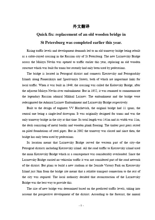
外文翻译Quick fix: replacement of an old wooden bridge inSt Petersburg was completed earlier this year.Rising traffic levels and development demands led to an old tramway bridge being rebuilt as a cable-stayed crossing in the Russian city of St Petersburg. The new Lazarevsky Bridge across the Malaya Nevka was opened to traffic earlier this year, replacing an old wooden structure which was built for trams but recently had only been used by pedestrians.The bridge is located in Petrograd district and connects Krestovsky and Petrogradsky Islands along Pionerskaya and Sportivnaya Streets, both of which are importanat links for local traffic. When it was built in 1949, the crossing was called the Koltovsky Bridge, after the adjacent Malaya Nevka river embankment. But in 1952, it was renamed to commemorate the legendary Russian admiral Mikhail Lazarev. The embankment and the bridge were redesignated the Admiral Lazarev Embankment and Lazarevsky Bridge respectively.Built to the design of engineer VV Blazhevich, the original bridge had 11 spans, the central one being a single-leaf drawspan. It was originally designed for trams and was the only tramway bridge in the city at that time. Its total length was 141m and its width was 11m, the deck consisting of metal baulks and wooden plank flooring. The timber post piers rested on piled foundations of steel pipes. But in 2002 the tramway was closed and since then, the bridge has only been used by pedestrians.Its location meant that Lazarevsky Bridge served the western part of the city--the Petrograd districts including Krestovsky island. All the road traffic to Krestovsky island used the main Krestovsky Bridge which as a consequence was considerably overloaded. Since the Lazarevsky Bridge carried no vehicular traffic it was not considered part of the road network of the district. But plans to build a new stadium at the Seaside Victory Park on Krestovsky Island just 3km from the bridge site meant that a reliable transport connection to the rest of the city was required. The local authority decided that reconstruction of the Lazarevsky Bridge was the best way to provide this.The size of new bridge was determined based on the predicted traffic levels, taking into account the prospective development of the district. According to the forecast, the annualaverage daily traffic intensity on Lazarevsky Bridge will rise to 16,000 vehicles per day by 2025. Peak loads occur during major sporting events at the stadium when the bridge will be required to help relieve the area of traffic within one hour. This traffic flow includes 4,500 to 5,000 cars, so even if the Petrovsky Bridge were to be rebuilt, the Lazarevsky Bridge needed two lanes of traffic in both directions in order to do this.Taking into consideration the fact that the timber structures of the bridge had been in use for more than 55 years, if the bridge reconstruction had been restricted to the widening and strengthening of the existing superstructure and piers, it would not have ensured the longevity of the fixed bridge and might have led to high operation costs. Another consideration was that the appearance of a multi-span structure with bulky piers would not have fitted into the architectural style that is emerging with construction of modern buildings on Krestovsky Island and the adjacent embankments.As a result, the decision was taken to completely demolish the existing bridge and replace it with a new structure on the same alignment. As part of the project, some of Sportivnaya Street on the right bank had to be widened, and improvement of the adjacent area was also included.The history of the project dates back more than a decade to 1998, when JSC Institute Strojproect won the tender to carry out a feasibility study into the reconstruction of Lazarevsky Bridge and its approaches.Even at this time, the architect Igor Serebrennikov had developed an original architectural concept of the bridge which involved use of a cable-stayed system. This concept was approved by the city's committee for development but financial problems meant that the design was suspended for seven years before it resumed.In 2003, the project was included in the target programme of design and survey works, and the tender for design development was officially announced. Again these works were awarded to JSC Institute Strojproect. The reconstruction design was completed in 2007 and was received positively by the State Expert Review Board; construction began at the end of that year.The structural concept of the bridge was approved based on the comparison of technical and economical options. One of the main restrictions was the strict limitation on the superstructure construction depth. On the one hand, it was limited by the need to maintainunderbridge clearance for navigation, while on the other hand the deck level was governed by the height of Admiral Lazarev Embankment, which could not be raised, according to the requirements of the committee for protection of monuments.To meet these almost incompatible conditions it was necessary to make the longitudinal profile of the deck with a vertical curve of radius 1,000m, a radius which is allowable only for very constrained conditions. But even with this minimum vertical curve radius, the limitation for the deck construction depth remained fairly strict--it had to be 1.4m at the maximum. This condition could be met either by a classic five-span continuous beam scheme or by a cable-stayed system. The costs of both options are practically the same but the cable-stayed option was preferred as it was considered more attractive from the architectural point of view. Another benefit was that it would take less time for construction as there was no need for intermediate piers to be built in the river bed.The unconventional appearance of the structure, particularly the shape of the tower and its asymmetric arrangement with its single span, put demands on the design abilities of the engineers from JSC Institute Strojproect, requiring them to cope with non-standard problems. One such problem was the need to provide the required rigidity to the deck while at the same time minimising its weight in order to decrease the moments in the tower elements and balance the system. Hence a single-span cable-stayed bridge with steel deck, orthotropic carriageway slab and a steel tower was selected for construction. The deck is supported by two rows of stays, with five stays in each row. The cable stays pass through the tower and are anchored in the reinforced concrete slab of the counterweight which is located beyond the bridge abutment on Krestovsky Island. The front arch of the tower, which is inclined towards the riverbed, carries the dead anchorages by which means the cable stays and backstays are secured. Tensioning of both sets of cables was carried out by means of active anchors located at the deck and in the counterweight slab. To minimise the total width of the deck, the anchorages are removed to the front surfaces of the main beams. The optimum force distribution in the tower elements was obtained by means of the arch shape that became sharper and elongated in the transverse section of the bridge.The deck consists of a system of longitudinal and transverse H-beams connected via the orthotropic slab with its U-shape stiffeners. The anchorages are located along the transverse beams. At the tower, the deck is rigidly fixed and at pier one it rests on Maurer sphericalbearings. The steel part of the deck is made of low-alloy steel grade 10 and 15 and the tower of steel grade 10 (400MPa).The cable stays are VSL standard monostrands and each one is made up of from 50 to 73 strands. The total length of strand used in the bridge is about 31km. Meanwhile the bridge deck pavement consists of two layers of asphalt/concrete 40mm and 50mm placed over the Technoelastomost-S membrane waterproofing layer.The pier foundations are formed of high pile caps resting on bored piles driven deep into the bearing stratum of firm clay. Above the foundation top, the piers are made of cast in situ concrete and faced with granite.Construction was carried out by Mostootryad No 75, a branch of OAO Mostotrest No 6, while the steel deck structure was manufactured by JSC Zavod Metallokonstruktsiy and the steel tower structure was manufactured by NPO Mostovik.For development of the detail design the specialists of automation division of the Institute prepared complex 3-D models of the tower and cable stay anchorages in PRO-E software which were used for analysis and as a basis for the fabrication of the structures by NPO Mostovik. The use of this successful PRO-E modelling enabled the complicated tower structures to be manufactured within a relatively short time.Taking into consideration the constraints imposed on the bridge construction, JSC Institute Strojproect suggested some modifications to the detailed design. One such proposal was to replace the cable backstays of the tower with rigid ties made of low-alloy steel grade 10 which would be fixed rigidly at the tower arches and counterweight. Temporary supports would be installed under the deck anchoragesThese modifications allowed the erection of the back-stays to be considerably simplified, and would also eliminate the need to tension the backstays, cutting in half the time for the cable-stay installation.In addition it meant that the cable-stays supporting the deck could be tensioned in a single operation, once the asphalt and concrete pavement had been installed on the bridge. Analysis included successive tensioning of cable-stay pairs from the longest pair down to the shortest pair with the subsequent final tensioning of the two longest pairs. Apart from the forces, the vertical displacements of the deck at the 'breakaway' points on the temporary supports had to be controlled. The actual tensioning works were carried out in compliance with the designsolutions. The data on the forces and displacements at each stage were handed over by the general contractor to the designers, and if necessary, the required corrections were introduced to the design. On the whole, the calculated data showed a high correlation with the actual parameters.In fact it took the general contractor only 17 months to complete construction of all the works involved in the bridge construction. The new cable-stayed bridge has fitted harmoniously into the surrounding landscape. By avoiding placement of intermediate piers in the riverbed it was possible to open up views along the Malaya Nevka. The arch tower acts as a symbolic gateway to the island and stands out distinctly against its background of sky and trees. The architectural expressiveness of the bridge is determined by the general asymmetrical composition and the dynamic shape of the tower formed by two inclined arches, a light and gently-curved deck, and the elegant outline of the cable stay arrangement. At night time, the appearance of the bridge is highlighted by architectural lighting.Tatiana Gurevich is project manager and Yuri Krylov is head of the structural steel department at JSC Institute Strojproect桥梁的快速修复——圣彼得堡一座旧木桥今年的更换工作在俄罗斯的圣彼得堡,崛起的交通水平和发展要求促使一个旧的电车轨道桥被改造为一个斜拉桥。


日本钢结构桥资料
日本钢桥新技术资料
日本是钢桥的王国,钢桥的结构形式随着时代的发展而不断地进行着改进。
教科书里介绍的结构形式有许多已经过时,日本桥梁建设协会的资料是实际工程设计的参考资料。
少数主梁桥
少数主梁桥是通过采用大跨度的合成桥面板或PC桥面板,达到减少主梁数目,并使横梁,风撑结构简素化以至于省略的新形桥梁。
近年来已经成为一种常见的钢桥形式。
适用于曲率半径大于700米的场合,经济跨径30到80米。
特长:由于采用合成桥面板或PC桥面板,提高了桥面板的跨度。
合成桥面板的底钢板同时兼做混凝土的模板。
现场打设的PC桥面板或工厂预制的桥面板均可对应。
由于桥面板跨度的增大,减少了主梁数目。
横梁的间隔也达到10米程度,横梁可以直接使用型材。
通过桥面板抵抗横方向的荷重,省略了下风撑。
除去强风地域,一直到70米均可保证抗风安全性。
跨径再大的话需要对抗风做特别的考虑。
狭小箱梁桥
狭小箱梁桥的主梁比从前的箱梁窄,翼缘的板厚较大,纵向加强肋的设置个数少,省略了横向加强肋,并且通过使用大跨度的合成桥面板,PC桥面板,简化了床组结构。
适用于曲率半径大于300米的场合,经济跨径60-110米。
特长:纵加强肋的设置个数大大减少,或者省略横加强肋。
较大跨径时,虽然箱梁断面较宽,箱内结构也可以简素化。
例如最大跨径97.6米,梁高3.1米,腹板间隔2.5米的狭小箱梁,但纵加强肋只设了一处。
当上下线一体化时狭小箱梁。
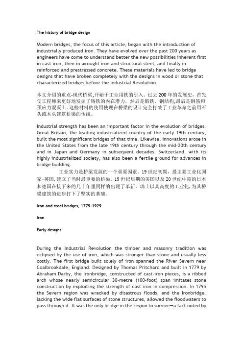
The history of bridge designModern bridges, the focus of this article, began with the introduction of industrially produced iron. They have evolved over the past 200 years as engineers have come to understand better the new possibilities inherent first in cast iron, then in wrought iron and structural steel, and finally in reinforced and prestressed concrete. These materials have led to bridge designs that have broken completely with the designs in wood or stone that characterized bridges before the Industrial Revolution.本文介绍的重点-现代桥梁,开始于工业用铁的引入。
过去200年的发展史,首先使工程师来更好地发掘了铸铁的内在潜力,然后是锻铁、钢结构,最后是钢筋和预应力混凝土。
这些材料的使用使现在桥梁的设计完全打破了工业革命之前用石头或木头建筑桥梁的传统。
Industrial strength has been an important factor in the evolution of bridges. Great Britain, the leading industrialized country of the early 19th century, built the most significant bridges of that time. Likewise, innovations arose in the United States from the late 19th century through the mid-20th century and in Japan and Germany in subsequent decades. Switzerland, with its highly industrialized society, has also been a fertile ground for advances in bridge building.工业实力是桥梁发展的一个重要因素。

‘钢结构(中英文)“2020年总目次Total Contents of Steel Construction(Chinese&English)in2020题㊀目Title 作㊀者Author期-页No.-Page题㊀目Title作㊀者Author期-页No.-Page综述ReviewResearch Progress on Cold-Formed Steel Structural Framing㊀Xuhong Zhou1-1冷弯型钢结构研究进展周绪红Application of Steel-Concrete Composite Structure in Ocean Engineering Jianguo Nie1-20钢-混凝土组合结构在海洋工程中的应用研究㊀聂建国Historical and Technological Developments of Steel Bridgesin Japan A Review Yozo Fujino,et al1-34日本钢桥的历史和技术发展综述藤野陽三,等Review of the Promotion and Application of Steel Structuresin Construction Yinquan Yu,et al1-59钢结构建筑的推广与应用综述郁银泉,等开合屋盖结构与技术标准的新进展范㊀重,等2-29 New Progress in Retractable Roof Structures and Technical Standards Zhong Fan,et alSteel Modular Construction and Its Applicability to the Building Industry in China㊀Tharaka Gunawardena,et al2-66钢结构模块化施工及其在中国建筑业中的应用㊀Tharaka Gunawardena,et al高强钢材钢结构抗震研究进展综述尹㊀飞,等3-1 Overview of Research Progress for Seismic Behavior of HighStrength Steel Structures Fei Yin,et al双钢板混凝土组合结构抗冲击性能的研究进展㊀赵唯以,等 3-26Research Advances of Impact Resistance of Steel Concrete Composite Structures Weiyi Zhao,et al输电塔风致响应数值模拟研究进展吕洪坤,等4-1 Progress in Numerical Simulation Study of Wind Induced Response of Transmission Towers Hongkun Lyu,et al高强结构钢连接研究进展李国强6-1 Progress of Research on High-Strength Structural Steel Connections Guoqiang LiRecent Development and Engineering Practice of Spatial Structures in China Suduo Xue7-1中国空间结构的近期发展与工程实践薛素铎Seismic Isolation and Vibration Reduction System of Large-Span Spatial Structures A Review㊀Qinghua Han,et al7-17大跨空间结构隔震减振体系研究综述韩庆华,等科研Research Experimental Investigation on Damage Identification of Cable-Stayed Arch-Truss Structures Using Modal Parameters㊀Bin Zeng,et al1-70张弦拱桁架结构基于模态参数的损伤识别试验㊀曾㊀滨,等Model Test Research on Seismic Performance of the Long-Span Steel Structure C1of Beijing Daxing International Airport Terminal Ailin Zhang,et al2-1北京大兴国际机场航站楼大跨度钢结构C1区抗震性能模型试验研究张爱林,等直接分析法在连续倒塌中的应用丁智霞,等2-13 The Application of Direct Analysis Method in Progressive Collapse Zhixia Ding,et al轴心受压杆件的弯扭屈曲王立军3-37 Torsion and Flexure Buckling of Centrally Loaded Members㊀Lijun Wang钢吊车梁稳定设计的合理方法童根树3-59 Rational Design of Crane Runway Girders Genshu TongT形钢管混凝土截面在双向弯矩和轴力联合作用下的相互作用曲线童根树,等4-11 Interaction Curves for Concrete-Filled T-Shaped Multi-Celled Steel Tube Sections Under Combined Biaxial Bending and Axial Force Genshu Tong,et al波纹腹板组合梁抗火性能参数分析周焕廷,等4-19 Parametric Analysis for Fire Resistance of Composite Steel-Concrete Beams with Corrugated Webs Accounting㊀Huanting Zhou,et al阿基米德铺砌柱面互承构型的可行性判定㊀陆飞云,等4-28 Feasibility Determination of Reciprocal Configurations on Cylindrical Surface from Archimedean Pavings㊀Feiyun Lu,et al冷弯薄壁G形截面柱轴压承载力研究向㊀弋,等5-1 Axial Load Capacity of Cold-Formed Steel G-Section Columns Yi Xiang,et al直立锁边金属屋面系统风吸破坏机理研究㊀张士翔,等5-10 Investigation on Failure Mechanism of the Standing Seam Metal Roof System Shixiang Zhang,et al钢-混凝土组合扁梁受弯性能理论分析与试验㊀龚㊀超,等6-41ⅠTheoretical Analysis and Experimental Study on Bending Behavior of Steel-Concrete Composite Flat Beams㊀Chao Gong,et alStudy on the Fluid-Structure Interaction of ETFE Cushions Under Uniform Flow Field Xiaofeng Wang,et al7-29均匀流场作用下ETFE气枕的流固耦合分析㊀王晓峰,等Importance Evaluation for Cables in the Loop Free Suspen-Dome Based on an Improved Strain Energy Method㊀Xiongyan Li,et al7-43基于改进应变能法的无环索弦支穹顶拉索重要性评价㊀李雄彦,等国家速滑馆索网结构形态分析关键问题研究㊀白光波,等 7-54Key Issues in Cable Net Form-Finding of the National SpeedSkating Oval Guangbo Bai,et al配置可更换角钢连接构造的钢框架试验研究㊀陈以一,等 8-1Tests on Moment Resistant Frame Connection withReplaceable Angles Yiyi Chen,et al太子城站钛锌蜂窝板芯层结构高温加速老化试验研究㊀蒋鸿鹄,等 8-17Experimental Study on High Temperature Accelerated Aging of Titanium-Zinc Honeycomb Core in Taizicheng RailwayStation Honghu Jiang,et al基于塑性损伤模型的钢-UHPC组合梁抗弯性能分析㊀朱经纬,等 8-24Analysis of Flexural Behavior of Steel-UHPC Composite Girders Based on Plastic Damage Model㊀Jingwei Zhu,et al金属屋面铝板抗风性能数值模拟研究赖燕德,等9-10 Numerical Simulation Investigation on Wind Resistance Performance of the Metal Roof Aluminum Sheet㊀Yande Lai,et al两铰圆弧车辐钢拱平面内弹塑性稳定设计㊀窦㊀超,等 9-17In-Plane Elastic-Plastic Stability Design of Pin Ended Circular Spoke Arches Chao Dou,et al张弦结构健康监测传感器布置优化方法亓玉台,等10-29 Optimization Method of Sensor Arrangement for Health Monitoring of String Structure Yutai Qi,et al大跨度钢桁梁桥的斜拉法提载加固分析何滨池,等10-34 Analysis of Load-Bearing and Reinforcement of Long Span Steel Truss Bridge with Inclined Cable㊀Binchi He,et al两边连接钢板式交错桁架塑性设计方法研究㊀甘㊀丹,等 11-1Study on Plastic Design Method of Staggered Truss Structure with Two-Side Connecting Steel Plates Dan Gan,et al钢筋混凝土柱-交错桁架结构抗震性能分析㊀郑㊀琦,等11-25 Pushover Analysis on the Seismic Performance of RC Column-Staggered Truss Structure Qi Zheng,et al交错桁架体系RC柱与桁架连接节点受力性能分析㊀周㊀祥,等11-40 Analysis on the Mechanical Behavior of RC Column to Truss Joint in Staggered Truss System Xiang Zhou,et al交错桁架结构设计理论方法与装配式集成技术应用研究㊀李瑞锋,等11-55 Design Theory Method of Staggered Truss Structure and Research on Assembled Integration Technology Application Ruifeng Li,et al带开槽耗能板的自复位方钢管混凝土柱-钢梁节点抗震性能有限元分析贾子涵,等12-1 Finite Element Analysis of Seismic Behavior of Self-Centering Concrete-Filled Square Steel Tubular Column-Steel Beam Joint with Slotted Energy Dissipation Plate㊀Zihan Jia,et al高强钢组合偏心支撑框架抗震性能远程协同试验研究㊀高㊀乐,等12-8 Remote Collaborative Test on Seismic Behavior of High Strength Steel Composite Eccentrically Braced Steel Frames Le Gao,et al低屈服点钢材剪切型阻尼器试验研究尧祖成,等12-16 Experimental Research on Low-Yield-Point Steel Shear Dampers Zucheng Yao,et al波折钢板剪力墙内嵌墙板与框架的相互作用分析㊀窦㊀超,等12-22 Analysis of Interaction Between Infill Plate and Frame in Steel Corrugated Shear Walls Chao Dou,et al连梁耦联作用对联肢钢板剪力墙稳定与变形影响的分析㊀吴星煌,等12-29 The Influence of Coupling Action of Coupling Beam on Stability and Deformation of Coupled Steel Plate Shear Wall㊀Xinghuang Wu,et al基于耦联比的联肢钢板剪力墙滞回性能分析㊀吴博睿,等12-36 Research on Hysteretic Behaviour of Coupled Steel Plate Shear Wall Structures Based on Degree of Coupling㊀Borui Wu,et al单元式双钢板组合剪力墙抗侧性能影响因素分析㊀刘㊀栋,等12-43 Parametric Analyses on Lateral Performance About Modular Composite Shear Wall with Double Steel Plates and Infill Concrete Dong Liu,et al考虑相关稳定的非线性金属轴压柱承载力直接强度法㊀袁焕鑫,等12-50ⅡThe Direct Strength Method for Interactive Buckling Resistance of Axial Compression Members Made of Non-Linear Metallic Materials Huanxin Yuan,et al设计Design北京新机场航站楼屋顶钢结构抗震设计研究㊀梁宸宇,等 5-19Seismic Design and Research of Roof Steel Structure of Beijing New Airport Terminal Building㊀Chenyu Liang,et al圆形不锈钢管混凝土压弯承载力设计方法研究㊀Pantha Subhash,et al 5-27Research on Design Methods of Load-Carrying for Circular Concrete Filled Stainless Steel Tube Beam Columns㊀Subhash Pantha,et al江门中微子实验中心探测器主体结构方案研究㊀张高明,等 9-1Research on the Main Structure of the Central Detector of Jiangmen Underground Neutrino Observatory(JUNO)㊀Gaoming Zhang,et al标准与规范Standard and Specification关于新版国标GB/T1591 2018‘低合金高强度结构钢“应用中的注意事项柴㊀昶,等6-50 Some Issus on Application for New National Standard GB/T 1591 2018High Strength Low Alloy Structural Steel㊀Chang Chai,et al中美钢结构规范对比研究Comparison of Chinese and US Code轴心受压杆件设计王立军4-39 Design of Axial Compression Member Lijun Wang中美建筑钢结构设计方法比较 焊缝连接石永久5-34 Comparisons Between Chinese and American Standards on Welded Connection Design Yongjiu Shi受弯杆件设计王立军6-55 Design of Flexural Members Lijun Wang中美建筑钢结构设计方法比较 螺栓连接石永久8-33 Comparisons Between Chinese and American Standards onBolted Connection Design Yongjiu Shi中美建筑钢结构钢材性能对比分析㊀吴耀华 9-26Performance Comparison of Structural Steels in Chinese and American Standards Yaohua Wu加工制作Processing and Manufacturing大跨径钢混组合箱梁工厂化制造关键技术李义成9-44 The Key Technology for Factory-Production of Large-Span Steel-Concrete Box Girder Yicheng Li飞雁式异形钢箱拱制作线形控制关键技术研究㊀郭延飞,等10-43Analysis on Manufacturing Control of Flying Geese Shaped Steel Box Arch Yanfei Guo,et al施工技术Construction Technology杭州奥体中心亚运三馆体育游泳馆施工关键技术㊀周观根,等10-1Key Construction Technology for Gymnasium and Natatoriumof Hangzhou Olympic Sports Center㊀Guangen Zhou,et al杭州奥体中心亚运三馆体育游泳馆施工过程分析㊀游桂模,等10-9Analysis of Construction Process for Gymnasium and Natatorium of Hangzhou Olympic Sports Center㊀Guimo You,et al杭州奥体中心综合训练馆钢结构施工关键技术㊀何㊀伟,等10-15Key Technology of Steel Structure Construction of Comprehensive Training Hall of Hangzhou Olympic Sports Center㊀Wei He,et al大跨度马鞍形单层正交索网结构定长索施工设计与安装技术张晋勋,等10-22 Construction Design and Installation Technology of Fixed Length Cable for Large Span Saddle Shaped Single Layer Orthogonal Cable Net Structure Jinxun Zhang,et al钢结构热点探析Hot Spot Analysis of Steel Structures雨篷被雪压塌,你知道积雪漂移吗?侯㊀杰,等4-50泉州酒店坍塌的可能原因是什么?潘继文,等5-50翼缘和腹板宽厚比等级不一致,如何考虑截面塑性发展系数?邹安宇,等6-65单边连接单角钢的两个折减系数要同时考虑吗?㊀邹安宇7-62拉条怎样才能同时约束檩条上㊁下翼缘?邹安宇8-57多跑楼梯,荷载要乘以放大系数?邹安宇,等9-52顶层局部框架要算刚度比吗?邹安宇10-51何时计算双向地震作用?邹安宇12-58新闻㊃亮点㊃人物News㊃Highlights㊃Personages让大地不惧震动|我国著名结构工程专家:周绪红院士㊀杨颖芳6-67Make the Earth Not Fear Vibrations|Chinaᶄs Famous Structural Engineering Expert:Academician Xuhong Zhou㊀Yingfang YangⅢ。

Structural Rehabilitation of Concrete Bridges with CFRP Composites-Practical Details and Applications Riyad S. ABOUTAHA1, and Nuttawat CHUTARAT2 ABSTRACT: Many old existing bridges are still active in the various networks, carrying all kinds of environments. Water, salt, and wind ; and to extend the service life of concrete bridges is by the use of carbon fiber reinforced polymer (CFRP) composites. There appear to be very limited guides on repair of deteriorated concrete bridges with CFRP composites. In this paper, guidelines for nondestructive evaluation (NDE), nondestructive testing (NDT), and rehabilitation of deteriorated concrete bridges with CFRP composites are presented. The effect of detailing on ductility and behavior of CFRP strengthened concrete bridges are also discussed and presented.KEYWORDS: Concrete deterioration, corrosion of steel, bridge rehabilitation, CFRP composites.1 IntroductionThere are several destructive external environmental factors that limit the service life of bridges. These factors include but not limited to chemical attacks, corrosion of reinforcing steel bars, carbonation of concrete, and chemical reaction of aggregate. If bridges were not well maintained, these factors may lead to a structural deficiency, which reduces the margin of safety, and may result in structural failure. In order to rehabilitate andor strengthen deteriorated existing bridges, thorough evaluation should be conducted. The purpose of theevaluation is to assess the actual condition of any existing bridge, and generally to examine the remaining strength and load carry capacity of the bridge.1 Associate Professor, Syracuse University, U.S.A.2 Lecturer, Sripatum University, Thailand.One attempt to restore the original condition, and to extend the service life of concrete bridges is by the use of carbon fiber reinforced polymer (CFRP) composites.In North America, Europe and Japan, CFRP extensively investigated and applied. Several design guides developed for strengthening of concrete bridges with CFRP composites. However, there appear to be very limited guides on repair of deteriorated concrete bridges with CFRP composites. This paper presents guidelines for repair of deteriorated concrete bridges, along with proper detailing. Evaluation, nondestructive testing, and rehabilitation of deteriorated concrete bridges with CFRP composites are presented. Successful application of CFRP composites requires good detailing as the forces developed in the CFRP sheets are transferred by bond at the concrete-CFRP interface. The effect of detailing on ductility and behavior of CFRP strengthened concrete bridges will also be discussed and presented.2 Deteriorated Concrete BridgesDurability of bridges is of major concern. Increasing number of bridges are experiencing significant amounts of deterioration prior to reaching their design service life. This premature deterioration considered a problem in terms of the structural integrity and safety of the bridge. In addition, deterioration of a bridge many cases, the root of a deterioration problem is caused by corrosion of steel reinforcement in concrete structures. Concrete normally acts to provide a against corrosion of the embedded reinforcement. However, corrosion will result in those cases that typically experience poor concrete quality, inadequate design or construction, and , may turn into a strength problem leading to a structural deficiency, as shown in Figure1.Figure1 Corrosion of the steel bars is leading to a structural deficiency3 Non-destructive Testing of Deteriorated Concrete Bridge PiersIn order to design a successful retrofit system, the condition of the existing bridge should be thoroughly evaluated. Evaluation of existing bridge elements or systems involves review of the asbuilt drawings, as well as accurate estimate of the condition of the existing bridge, as shown in Figure2. Depending on the purpose of evaluation, non-destructive tests may involve estimation of strength, salt contents, corrosion rates, alkalinity in concrete, etc.Figure2 Visible concrete distress marked on an elevation of a concrete bridgepierAlthough most of the non-destructive tests do not cause any damage to existing bridges, some NDT may cause minor local damage (e.g. drilled -destructive testing.In order to select the most appropriate non-destructive test for a particular case, the purpose of the test should be identified. In general, there are three types of NDT to investigate: (1) strength, (2) other structural properties, and (3) quality and durability. The strength methods may include; compressive test (e.g. core testrebound test (e.g. Windsor probe), and pullout test (anchor test).Other structural test methods may include; concrete cover thickness (cover-meter), locating rebars (rebar locator), rebar size (some rebar locatorsrebar data scan), concrete moisture (acquametermoisture meter), cracking (visual testimpact echoultrasonic pulse velocity), delamination (’s ratio (ultrasonic pulse velocity), thickness of concrete slab or wall (ultrasonic pulse velocity), CFRP debonding ( on concrete surface (visual inspection).Quality and durability test methods may include; rebar corrosion rate –field test, chloride profile field test, rebar corrosion analysis, rebar resistivity test, alkali-silica reactivity field test, concrete alkalinity test (carbonation field test), concrete permeability (field test for permeability).4 Non-destructive Evaluation of Deteriorated Concrete Bridge PiersThe process of evaluating the structural condition of an existing concrete bridge consists of collecting information, e.g. drawings and construction & inspection records, analyzing NDT data, and structural analysis of the bridge. The evaluation process can be summarized as follows: (1) Planning for the assessment, (2) Preliminary assessment, which involves examination of available documents, site inspection, materials assessment, and preliminary analysis, (3) Preliminary evaluation, this involves: examination phase, and judgmental phase, and finally (4) the cost-impact study.If the information is insufficient to conduct evaluation to a specific required level, then a detailed evaluation may be conducted following similar steps for the above-mentioned preliminary assessment, but in-depth assessment. Successful analytical evaluation of an existing deteriorated concrete bridge should consider the actual condition of the bridge and level of deterioration of various elements. Factors, e.g. actual concrete strength, level of damagedeterioration, actual size of corroded rebars, loss of bond between steel and concrete, etc. should be modeled into a detailed analysis. If such detailed analysis is difficult to accomplish within a reasonable period of time, then evaluation by field load testing of the actual bridge in question may be required.5 Bridge Rehabilitation with CFRP CompositesApplication of CFRP composite materials is becoming increasingly attractive to extend the service life of existing concretebridges. The technology of strengthening existing bridges with externally bonded CFRP composites was developed primarily in Japan (FRP sheets), and Europe (laminates). The use of these materials for strengthening existing concrete bridges started in the 1980s, first as a substitute to bonded steel plates, and then as a substitute for steel jackets for seismic retrofit of bridge columns. CFRP Composite materials are composed of fiber reinforcement bonded together with a resin matrix. The fibers provide the composite with its unique structural properties. The resin matrix supports the fibers, protect them, and transfer the applied load to the fibers through shearing stresses. Most of the commercially available CFRP systems in the construction market consist of uniaxial fibers embedded in a resin matrix, typically epoxy. Carbon fibers , which may limit the deformability of strengthened members. However, under traffic loads, local debonding between FRP sheets and concrete substrate would allow for acceptable level of global deformations before failure.CFRP composites could be used to increase the flexural and shear strength of bridge girders including pier cap beams, as shown in Figure3. In order to increase the ductility of CFRP strengthened concrete girders, the longitudinal CFRP composite sheets used for flexural strengthening should be anchored with transversediagonal CFRP anchors to prevent premature delamination of the longitudinal sheets due to localized debonding at the concrete surface-CFRP sheet interface. In order to prevent stress concentration and premature fracture of the CFRP sheets at the corners of concrete members, thecorners should be rounded at 50mm (2.0 inch) radius, as shown in Figure3.Deterioration of concrete bridge members due to corrosion of steel bars usually leads in loss of steel section and delamination of concrete cover. As a result, such deterioration may lead to structural deficiency that requires immediate attention. Figure4 shows rehabilitation of structurally deficient concrete bridge pier using CFRP composites.Figure3 Flexural and shear strengthening of concrete bridge pier with FRPcompositesFigure4 Rehabilitation of deteriorated concrete bridge pier with CFRPcomposites6 Summary and ConclusionsEvaluation, non-destructive testing and rehabilitation of deteriorated concrete bridges were presented. Deterioration of concrete bridge components due to corrosion may lead to structural deficiencies, e.g. flexural andor shear failures. Application of CFRP composite materials is becoming increasingly attractive solution to extend the service life of existing concrete bridges. CFRP composites could be utilized for flexural and shear strengthening, as well as for restoration of deteriorated concrete bridge components. The CFRP composite sheets should be well detailed to prevent stress concentration and premature fracture or delamination. For successful rehabilitation of concrete bridges in corrosive environments, acorrosion protection system should be used along with the CFRP system.碳纤维复合材料修复混凝土桥梁结构的详述及应用Riyad S. ABOUTAHA1, and Nuttawat CHUTARAT2摘要:在各式各样的公路交通网络中,许多现有的古老桥梁,在各种恶劣的环境下,如更重的荷载和更快的车辆等条件下,依然在被使用着。
钢桥发展前景钢桥作为一种重要的桥梁建设材料,其发展前景十分广阔。
随着经济的不断发展和城市建设的加快,对桥梁建设的需求日益增长,钢桥作为一种高强度、耐久性好、施工方便的材料,将会在未来的桥梁建设中扮演更加重要的角色。
首先,钢桥的使用具有很大的经济效益。
相比传统的混凝土桥梁,钢桥的成本更低。
传统的混凝土桥梁需要进行大量的土方开挖和基础建设,施工周期长,造价高。
而钢桥则可以进行工厂预制,减少现场施工工期,降低项目总成本。
此外,钢桥具有轻质高强度的特点,可以减少桥梁对地基的压力,进一步降低工程造价。
其次,钢桥的使用具有很大的环境效益。
钢材是一种可回收利用的材料,制造、维修和拆除钢桥的过程中产生的废弃物可以进行回收再利用。
相比之下,混凝土桥梁在建设和拆除过程中会产生大量的废弃物,对环境造成较大的负面影响。
此外,钢桥建设的工期相对较短,施工过程中对周边环境的干扰也较小,可以减少施工对周边居民生活的影响。
再次,钢桥具有较长的使用寿命和较好的耐久性。
钢材具有较高的强度和韧性,能够承受较大的荷载和变形。
而且,它不会受到腐蚀、虫蛀和火灾等自然灾害的影响,使用寿命较长。
而传统的混凝土桥梁在使用过程中容易出现开裂、病害等问题,需要进行频繁的维修和加固,造成较大的经济负担。
最后,钢桥具有较好的适应性和灵活性。
由于钢材具有较高的强度和韧性,可以制造更大跨度的桥梁,适应不同地区和交通需求的改变。
而且,钢桥可以进行拆卸和重组,方便在不同地点进行移动和使用,满足临时桥梁和紧急修复的需求。
这种灵活性可以缩短施工工期,提高桥梁的使用效率。
综上所述,钢桥作为一种重要的桥梁建设材料,其发展前景十分广阔。
随着经济的不断发展和城市建设的加快,对桥梁建设的需求将会不断增长。
钢桥具有经济高效、环境友好、使用寿命长以及适应性强的优势,将会在未来的桥梁建设中得到更多的应用。
外文文献翻译BRIDGE ENGINEERING AND AESTHETICSEvolvement of bridge Engineering,brief reviewAmong the early documented reviews of construction materials and structure types are the books of Marcus Vitruvios Pollio in the first century B.C.The basic principles of statics were developed by the Greeks , and were exemplified in works and applications by Leonardo da Vinci,Cardeno,and Galileo.In the fifteenth and sixteenth century, engineers seemed to be unaware of this record , and relied solely on experience and tradition for building bridges and aqueducts .The state of the art changed rapidly toward the end of the seventeenth century when Leibnitz, Newton, and Bernoulli introduced mathematical formulations. Published works by Lahire (1695)and Belidor (1792) about the theoretical analysis of structures provided the basis in the field of mechanics of materials .Kuzmanovic(1977) focuses on stone and wood as the first bridge-building materials. Iron was introduced during the transitional period from wood to steel .According to recent records , concrete was used in France as early as 1840 for a bridge 39 feet (12 m) long to span the Garoyne Canal at Grisoles, but reinforced concrete was not introduced in bridge construction until the beginning of this century . Prestressed concrete was first used in 1927.Stone bridges of the arch type (integrated superstructure and substructure) were constructed in Rome and other European cities in the middle ages . These arches were half-circular , with flat arches beginning to dominate bridge work during the Renaissance period. This concept was markedly improved at the end of the eighteenth century and found structurally adequate to accommodate future railroad loads . In terms of analysis and use of materials , stone bridges have not changed much ,but the theoretical treatment was improved by introducing the pressure-line concept in the early 1670s(Lahire, 1695) . The arch theory was documented in model tests where typical failure modes were considered (Frezier,1739).Culmann(1851) introduced the elastic center method for fixed-end arches, and showed that three redundant parameters can be found by the use of three equations of coMPatibility.Wooden trusses were used in bridges during the sixteenth century when Palladio built triangular frames for bridge spans 10 feet long . This effort also focused on the three basic principles og bridge design : convenience(serviceability) ,appearance , and endurance(strength) . several timber truss bridges were constructed in western Europe beginning in the 1750s with spans up to 200 feet (61m) supported on stone substructures .Significant progress was possible in the United States and Russia during the nineteenth century ,prompted by the need to cross major rivers and by an abundance of suitable timber . Favorable economic considerations included initial low cost and fast construction .The transition from wooden bridges to steel types probably did not begin until about 1840 ,although the first documented use of iron in bridges was the chain bridge built in 1734 across the Oder River in Prussia . The first truss completely made of iron was in 1840 in the United States , followed by England in 1845 , Germany in 1853 , and Russia in 1857 . In 1840 , the first iron arch truss bridge was built across the Erie Canal at Utica .The Impetus of AnalysisThe theory of structuresThe theory of structures ,developed mainly in the ninetheenth century,focused on truss analysis, with the first book on bridges written in 1811. The Warren triangular truss was introduced in 1846 ,supplemented by a method for calculating the correcet forces .I-beams fabricated from plates became popular in England and were used in short-span bridges.In 1866, Culmann explained the principles of cantilever truss bridges, and one year later the first cantilever bridge was built across the Main River in Hassfurt, Germany, with a center span of 425 feet (130m) . The first cantilever bridge in the United States was built in 1875 across the Kentucky River.A most impressive railway cantilever bridge in the nineteenth century was the First of Forth bridge , built between 1883 and 1893 , with span magnitudes of 1711 feet (521.5m). At about the same time , structural steel was introduced as a prime material in bridge work , although its quality was often poor . Several early examples are the Eads bridge in St.Louis ; the Brooklyn bridge in New York ; and the Glasgow bridge in Missouri , all completed between 1874 and 1883.Among the analytical and design progress to be mentioned are the contributions of Maxwell , particularly for certain statically indeterminate trusses ; the books by Cremona (1872) on graphical statics; the force method redefined by Mohr; and the works by Clapeyron who introduced the three-moment equations.The Impetus of New MaterialsSince the beginning of the twentieth century , concrete has taken its place as one of the most useful and important structural materials . Because of the coMParative ease with which it can be molded into any desired shape , its structural uses are almost unlimited . Wherever Portland cement and suitable aggregates are available , it can replace other materials for certain types of structures, such as bridge substructure and foundation elements .In addition , the introduction of reinforced concrete in multispan frames at the beginning of this century imposed new analytical requirements . Structures of a high order of redundancy could not be analyzed with the classical methods of the nineteenth century .The importance of joint rotation was already demonstrated by Manderla (1880) and Bendixen (1914) , who developed relationships between joint moments and angular rotations from which the unknown moments can be obtained ,the so called slope-deflection method .More simplifications in frame analysis were made possible by the work of Calisev (1923) , who used successive approximations to reduce the system of equations to one simple expression for each iteration step . This approach was further refined and integrated by Cross (1930) in what is known as the method of moment distribution .One of the most import important recent developments in the area of analytical procedures is the extension of design to cover the elastic-plastic range , also known as load factor or ultimate design. Plastic analysis was introduced with some practical observations by Tresca (1846) ; and was formulated by Saint-Venant (1870) , The concept of plasticity attracted researchers and engineers after World War Ⅰ, mainly in Germany , with the center of activity shifting to England and the United States after World War Ⅱ.The probabilistic approach is a new design concept that is expected to replace the classical deterministic methodology.A main step forward was the 1969 addition of the Federal Highway Adiministration (FHWA)”Criteria for Reinforced Concrete Bridge Members “ that covers strength and serviceability at ultimate design . This was prepared for use in conjunction with the 1969 American Association of State Highway Offficials (AASHO) Standard Specification, and was presented in a format that is readily adaptable to the development of ultimate design specifications .According to this document , the proportioning of reinforced concrete members ( including columns ) may be limited by various stages of behavior : elastic , cracked , andultimate . Design axial loads , or design shears . Structural capacity is the reaction phase , and all calculated modified strength values derived from theoretical strengths are the capacity values , such as moment capacity ,axial load capacity ,or shear capacity .At serviceability states , investigations may also be necessary for deflections , maximum crack width , and fatigue . Bridge TypesA notable bridge type is the suspension bridge , with the first example built in the United States in 1796. Problems of dynamic stability were investigated after the Tacoma bridge collapse , and this work led to significant theoretical contributions Steinman ( 1929 ) summarizes about 250 suspension bridges built throughout the world between 1741 and 1928 .With the introduction of the interstate system and the need to provide structures at grade separations , certain bridge types have taken a strong place in bridge practice. These include concrete superstructures (slab ,T-beams,concrete box girders ), steel beam and plate girders , steel box girders , composite construction , orthotropic plates , segmental construction , curved girders ,and cable-stayed bridges . Prefabricated members are given serious consideration , while interest in box sections remains strong .Bridge Appearance and AestheticsGrimm ( 1975 ) documents the first recorded legislative effort to control the appearance of the built environment . This occurred in 1647 when the Council of New Amsterdam appointed three officials . In 1954 , the Supreme Court of the United States held that it is within the power of the legislature to determine that communities should be attractive as well as healthy , spacious as well as clean , and balanced as well as patrolled . The Environmental Policy Act of 1969 directs all agencies of the federal government to identify and develop methods and procedures to ensure that presently unquantified environmental amentities and values are given appropriate consideration in decision making along with economic and technical aspects .Although in many civil engineering works aesthetics has been practiced almost intuitively , particularly in the past , bridge engineers have not ignored or neglected the aesthetic disciplines .Recent research on the subject appears to lead to a rationalized aesthetic design methodology (Grimm and Preiser , 1976 ) .Work has been done on the aesthetics of color ,light ,texture , shape , and proportions , as well as other perceptual modalities , and this direction is both theoretically and empirically oriented .Aesthetic control mechanisms are commonly integrated into the land-use regulations and design standards . In addition to concern for aesthetics at the state level , federal concern focuses also on the effects of man-constructed environment on human life , with guidelines and criteria directed toward improving quality and appearance in the design process . Good potential for the upgrading of aesthetic quality in bridge superstructures and substructures can be seen in the evaluation structure types aimed at improving overall appearance .LOADS AND LOADING GROUPSThe loads to be considered in the design of substructures and bridge foundations include loads and forces transmitted from the superstructure, and those acting directly on the substructure and foundation .AASHTO loads . Section 3 of AASHTO specifications summarizes the loads and forces to be considered in the design of bridges (superstructure and substructure ) . Briefly , these are dead load ,live load , iMPact or dynamic effect of live load , wind load , and other forces such as longitudinal forces , centrifugal force ,thermal forces , earth pressure , buoyancy , shrinkage andlong term creep , rib shortening , erection stresses , ice and current pressure , collision force , and earthquake stresses .Besides these conventional loads that are generally quantified , AASHTO also recognizes indirect load effects such as friction at expansion bearings and stresses associated with differential settlement of bridge components .The LRFD specifications divide loads into two distinct categories : permanent and transient .Permanent loadsDead Load : this includes the weight DC of all bridge components , appurtenances and utilities, wearing surface DW and future overlays , and earth fill EV. Both AASHTO and LRFD specifications give tables summarizing the unit weights of materials commonly used in bridge work .Transient LoadsVehicular Live Load (LL)Vehicle loading for short-span bridges :considerable effort has been made in the United States and Canada to develop a live load model that can represent the highway loading more realistically than the H or the HS AASHTO models . The current AASHTO model is still the applicable loading.桥梁工程和桥梁美学桥梁工程的发展概况早在公元前1世纪,Marcus Vitrucios Pollio 的著作中就有关于建筑材料和结构类型的记载和评述。
中英文对照外文翻译文献(文档含英文原文和中文翻译)Recent Research and Design Developments in Steel and Composite Steel-concrete Structures in USAThe paper will conclude with a look toward the future of structural steel research.1. Research on steel bridgesThe American Association of State Transportation and Highway Officials (AASTHO) is the authority that promulgates design standards for bridges in the US. In 1994 it has issued a new design specification which is a Limit States Design standard that is based on the principles of reliability theory. A great deal of work went into the development of this code in the past decade, especially on calibration and on the probabilistic evaluation of the previous specification. The code is now being implemented in the design office, together with the introduction of the SystemeInternationale units. Many questions remain open about the new method of design, and there are many new projects that deal with the reliability studies of the bridge as a system. One such current project is a study to develop probabilistic models, load factors, and rational load-combination rules for the combined effects of live-load and wind; live-load and earthquake; live-load, wind and ship collision; and ship collision, wind, and scour. There are also many field measurements of bridge behavior, using modern tools of inspection and monitoring such as acoustic emission techniques and other means of non-destructive evaluation. Such fieldwork necessitates parallel studies in the laboratory, and the evolution of ever more sophisticated high-technology data transmission methods.America has an aging steel bridge population and many problems arise from fatigue and corrosion. Fatigue studies on full-scale components of the Williamsburg Bridge in New York have recently been completed at Lehigh University. A probabilistic AASTHO bridge evaluation regulation has been in effect since 1989, and it is employed to assess the future useful life of structures using rational methods that include field observation and measurement together with probabilistic analysis. Such an activity also fosters additional research because many issues are still unresolved. One such area is the study of the shakedown of shear connectors in composite bridges. This work has been recently completed at the University of Missouri.In addition to fatigue and corrosion, the major danger to bridges is the possibility of earthquake induced damage. This also has spawned many research projects on the repair and retrofit of steel superstructures and the supporting concrete piers. Many bridges in the country are being strengthened for earthquake resistance. One area that is receiving much research attention is the strengthening of concrete piers by "jacketing" them by sheets of high-performance reinforced plastic.The previously described research deals mainly with the behavior of existing structures and the design of new bridges. However, there is also a vigorous activity on novel bridge systems. This research is centered on the application of high-performance steels for the design of innovative plate and box-girder bridges, such as corrugated webs, combinations of open and closed shapes, and longer spansfor truss bridges. It should be mentioned here that, in addition to work on steel bridges, there is also very active research going on in the study of the behavior of prestressed concrete girders made from very high strength concrete. The performance and design of smaller bridges using pultruded high-performance plastic composite members is also being studied extensively at present. New continuous bridge systems with steel concrete composite segments in both the positive moment and the negative moment regions are being considered. Several researchers have developed strong capabilities to model the three-dimensional non-linear behavior of individual plate girders, and many studies are being performed on the buckling and post-buckling characteristics of such panion experimental studies are also made,especially on members built from high-performance steels. A full-scale bridge of such steel has been designed, and will soon be constructed and then tested under traffic loading. Research efforts are also underway on the study of the fatigue of large expansion joint elements and on the fatigue of highway sign structures.The final subject to be mentioned is the resurgence of studies of composite steel concrete horizontally curved steel girder bridges. A just completed project at the University of Minnesota monitored the stresses and the deflections in a skewed and curved bridge during all phases of construction, starting from the fabrication yard to the completed bridge.~ Excellent correlation was found to exist between the measured stresses and deformations and the calculated values. The stresses and deflections during construction were found to be relatively small, that is, the construction process did not cause severe trauma to the system. The bridge has now been tested under service loading, using fully loaded gravel trucks, for two years, and it will continue to be studied for further years to measure changes in performance under service over time. A major testing project is being conducted at the Federal Highway Administration laboratory in Washington, DC, where a half-scale curved composite girder bridge is currently being tested to determine its limit states. The test-bridge was designed to act as its own test-frame, where various portions can be replaced after testing. Multiple flexure tests, shear tests, and tests under combined bending and shear, are thus performed with realistic end-conditions and restraints. The experiments arealso modeled by finite element analysis to check conformance between reality and prediction. Finally design standards will be evolved from the knowledge gained. This last project is the largest bridge research project in the USA at the present time.From the discussion above it can be seen that even though there is no large expansion of the nation's highway and railroad system, there is extensive work going on in bridge research. The major challenge facing both the researcher and the transportation engineer is the maintenance of a healthy but aging system, seeing to its gradual replacement while keeping it safe and serviceable.2. Research on steel members and framesThere are many research studies on the strength and behavior of steel building structures. The most important of these have to do with the behavior and design of steel structures under severe seismic events. This topic will be discussed later in this paper. The most significant trends of the non-seismic research are the following: "Advanced" methods of structural analysis and design are actively studied at many Universities, notably at Cornell, Purdue, Stanford, and Georgia Tech Universities. Such analysis methods are meant to determine the load-deformation behavior of frames up to and beyond failure, including inelastic behavior, force redistribution, plastic hinge formation, second-order effects and frame instability. When these methods are fully operational, the structure will not have to undergo a member check, because the finite element analysis of the frame automatically performs this job. In addition to the research on the best approaches to do this advanced analysis, there are also many studies on simplifications that can be easily utilized in the design office while still maintaining the advantages of a more complex analysis. The advanced analysis method is well developed for in-plane behavior, but much work is yet to be done on the cases where bi-axial bending or lateraltorsional buckling must be considered. Some successes have been achieved, but the research is far from complete.Another aspect of the frame behavior work is the study of the frames with semirigid joints. The American Institute of Steel Construction (AISC) has published design methods for office use. Current research is concentrating on the behavior ofsuch structures under seismic loading. It appears that it is possible to use such frames in some seismic situations, that is, frames under about 8 to 10 stories in height under moderate earthquake loads. The future of structures with semi-rigid frames looks very promising, mainly because of the efforts of researchers such as Leon at Georgia Tech University, and many others.Research on member behavior is concerned with studying the buckling and post buckling behavior of compact angle and wide-flange beam members by advanced commercial finite element programs. Such research is going back to examine the assumptions made in the 1950s and 1960s when the plastic design compactness and bracing requirements were first formulated on a semi-empirical basis. The non-linear finite element computations permit the "re-testing" of the old experiments and the performing of new computer experiments to study new types of members and new types of steels. White of Georgia Tech is one of the pioneers in this work. Some current research at the US military Academy and at the University of Minnesota by Earls is discussed later in this report. The significance of this type of research is that the phenomena of extreme yielding and distortion can be efficiently examined in parameter studies performed on the computer. The computer results can be verified with old experiments, or a small number of new experiments. These studies show a good prospect fornew insights into old problems that heretofore were never fully solved.3. Research on cold-formed steel structuresNext to seismic work, the most active part of research in the US is on cold-formed steel structures. The reason for this is that the supporting industry is expanding, especially in the area of individual family dwellings. As the cost of wood goes up, steel framed houses become more and more economical. The intellectual problems of thin-walled structures buckling in multiple modes under very large deformations have attracted some of the best minds in stability research. As a consequence, many new problems have been solved: complex member stiffening systems, stability and bracing of C and Z beams, composite slabs, perforated columns, standing-seam roof systems, bracing and stability of beams with very complicatedshapes, cold-formed members with steels of high yield stress-to-tensile strength ratio, and many other interesting applications. The American Iron and Steel Institute (AISI) has issued a new expanded standard in 1996 that brought many of these research results into the hands of the designer.4. Research on steel-concrete composite structuresAlmost all structural steel bridges and buildings in the US are built with composite beams or girders. In contrast, very few columns are built as composite members. The area of composite Column research is very active presently to fill up the gap of technical information on the behavior of such members. The subject of steel tubes filled with high-strength concrete is especially active. One of the aims of research performed by Hajjar at the University of Minnesota is to develop a fundamental understanding of the various interacting phenomena that occur in concrete-filled columns and beam-columns under monotonic and cyclic load. The other aim is to obtain a basic understanding of the behavior of connections of wide-flange beams to concrete filled tubes.Other major research work concerns the behavior and design of built-up composite wide-flange bridge girders under both positive and negative bending. This work is performed by Frank at the University of Texas at Austin and by White of Georgia Tech, and it involves extensive studies of the buckling and post-buckling of thin stiffened webs. Already mentioned is the examination of the shakedown of composite bridges. The question to be answered is whether a composite bridge girder loses composite action under repeated cycles of loads which are greater than the elastic limit load and less than the plastic mechanism load. A new study has been initiated at the University of Minnesota on the interaction between a semi-rigid steel frame system and a concrete shear wall connected by stud shear connectors.5. Research on connectionsConnection research continues to interest researchers because of the great variety of joint types. The majority of the connection work is currently related to the seismic problems that will be discussed in the next section of this paper. The most interest in non-seismic connections is the characterization of the monotonic moment-rotationbehavior of various types of semi-rigid joints.6. Research on structures and connections subject to seismic forcesThe most compelling driving force for the present structural steel research effort in the US was the January 17, 1994 earthquake in Northridge, California, North of Los Angeles. The major problem for steel structures was the extensive failure of prequalified welded rigid joints by brittle fracture. In over 150 buildings of one to 26 stories high there were over a thousand fractured joints. The buildings did not collapse, nor did they show any external signs of distress, and there were no human injuries or deaths. A typical joint is shown in Fig. 2.2.1.In this connection the flanges of the beams are welded to the flanges of the column by full-penetration butt welds. The webs are bolted to the beams and welded to the columns. The characteristic features of this type of connection are the backing bars at the bottom of the beam flange, and the cope-holes left open to facilitate the field welding of the beam flanges. Fractures occurred in the welds, in the beam flanges, and/or in the column flanges, sometimes penetrating into the webs.Once the problem was discovered several large research projects were initiated at various university laboratories, such as The University of California at San Diego, the University of Washington in Seattle, the University of Texas at Austin, Lehigh University at Bethlehem, Pennsylvania, and at other places. The US Government under the leadership of the Federal Emergency Management Agency (FEMA) instituted a major national research effort. The needed work was deemed so extensivethat no single research agency could hope to cope with it. Consequently three California groups formed a consortium which manages the work:(1) Structural Engineering Association of California.(2) Applied Technology Council.(3) California Universities for Research in Earthquake Engineering.The first letters in the name of each agency were combined to form the acronym SAC, which is the name of the joint venture that manages the research. We shall read much from this agency as the results of the massive amounts of research performed under its aegis are being published in the next few years.The goals of the program are to develop reliable, practical and cost-effective guidelines for the identification and inspection of at-risk steel moment frame buildings, the repair or upgrading of damaged buildings, the design of new construction, and the rehabilitation of undamaged buildings.~ As can be seen, the scope far exceeds the narrow look at the connections only. The first phase of the research was completed at the end of 1996, and its main aim was to arrive at interim guidelines so that design work could proceed. It consisted of the following components:~ A state-of-the-art assessment of knowledge on steel connections.~ A survey of building damage.~ The evaluation of ground motion.~ Detailed building analyses and case studies.~ A preliminary experimental program.~ Professional training and quality assurance programs.~ Publishing of the Interim Design Guidelines.A number of reports were issued in this first phase of the work. A partial list of these is appended at the end of this paper.During the first phase of the SAC project a series of full-scale connection tests under static and, occasionally, dynamic cyclic tests were performed. Tests were of pre-Northridge-type connections (that is, connections as they existed at the time of the earthquake), of repaired and upgraded details, and of new recommendedconnection details. A schematic view of the testing program is illustrated in Fig.2.2.2 Some recommended strategies for new design are schematically shown in Fig. 2.2.3.Fig. 2.2.3 some recommended improvements in the interim guidelinesThe following possible causes, and their combinations, were found to have contributed to tile connection failures:~ Inadequate workmanship in the field welds.~ Insufficient notch-toughness of the weld metal.~ Stress raisers caused by the backing bars.~ Lack of complete fusion near the backing bar.~ Weld bead sizes were too big.~ Slag inclusion in the welds.While many of the failures can be directly attributed to the welding and thematerial of the joints, there are more serious questions relative to the structural system that had evolved over the years mainly based on economic considerations.' The structural system used relatively few rigid-frames of heavy members that were designed to absorb the seismic forces for large parts of the structure. These few lateral-force resistant frames provide insufficient redundancy. More rigid-frames with smaller members could have provided a tougher and more ductile structural system. There is a question of size effect: Test results from joints of smaller members were extrapolated to joints with larger members without adequate test verification. The effect of a large initial pulse may have triggered dynamic forces that could have caused brittle fracture in joints with fracture critical details and materials. Furthermore, the yield stress of the beams was about 30% to 40% larger than the minimum specified values assumed in design, and so the connection failed before the beams, which were supposed to form plastic hinges.As can be seen, there are many possible reasons for this massive failure rate, and there is blame to go around for everyone. No doubt, the discussion about why and how the joints failed will go on for many more years. The structural system just did not measure up to demands that were more severe than expected. What should be kept in mind, however, is that no structure collapsed or caused even superficial nonstructural damage, and no person was injured or killed. In the strictest sense the structure sacrificed itself so that no physical harm was done to its users. The economic harm, of course, was enormous.7. Future directions of structural steel research and conclusionThe future holds many challenges for structural steel research. The ongoing work necessitated by the two recent earthquakes that most affected conventional design methods, namely, the Northridge earthquake in the US and the Kobe earthquake in Japan, will continue well into the first decade of the next Century. It is very likely that future disasters of this type will bring yet other problems to the steel research community. There is a profound change in the philosophy of design for disasters: We can no longer be content with saving lives only, but we must also design structures which will not be so damaged as to require extensive repairs.Another major challenge will be the emergence of many new materials such as high-performance concrete and plastic composite structures. Steel structures will continually have to face the problem of having to demonstrate viability in the marketplace. This can only be accomplished by more innovative research. Furthermore, the new comprehensive limit-states design codes which are being implemented worldwide, need research to back up the assumptions used in the theories.Specifically, the following list highlights some of the needed research in steel structures:Systems reliability tools have been developed to a high degree of sophistication. These tools should be applied to the studies of bridge and building structures to define the optimal locations of monitoring instruments, to assess the condition and the remaining life of structures, and to intelligently design economic repair and retrofit operations.New developments in instrumentation, data transfer and large-scale computation will enable researchers to know more about the response of structures under severe actions, so that a better understanding of "real-life" behavior can be achieved.The state of knowledge about the strength of structures is well above the knowledge about serviceability and durability. Research is needed on detecting and preventing damage in service and from deterioration.The areas of fatigue and fracture mechanics on the one hand, and the fields of structural stability on the other hand, should converge into a more Unified conceptual entity.The problems resulting from the combination of inelastic stability and low-cycle fatigue in connections subject to severe cyclic loads due to seismic action will need to be solved.The performance of members, connections and connectors (e.g., shear connectors) under severe cyclic and dynamic loading requires extensive new research, including shakedown behavior.The list could go on, but one should never be too dogmatic about the future ofsuch a highly creative activity as research. Nature, society and economics will provide sufficient challenges for the future generation of structural engineers.近期美国在钢结构和钢筋混凝土结构研究和设计方面的发展这篇文章将总结对钢结构的研究展望.1.钢结构桥梁的研究美国国家运输和公路官员协会(AASTH0)是为美国桥梁发布设计标准的权威。
日本钢桥概况及中国钢桥的应用与发展日本是一个拥有众多桥梁的岛国,钢桥是其中重要的一种桥梁形式。
首先,我将介绍一下日本钢桥的概况,然后再谈谈中国钢桥的应用与发展。
日本钢桥的概况:1.历史悠久:日本钢桥的历史可以追溯到19世纪末20世纪初,早期采用的是铁框架结构,发展到后来大规模应用钢结构,如钢筋混凝土梁桥、悬索桥、斜拉桥等。
2.技术先进:日本在钢桥的设计和制造方面拥有丰富的经验和先进的技术,其桥梁工程研究所对钢桥的研究不断取得突破,如使用新型材料、新型构造和新型施工方法等。
3.良好维护管理:日本对桥梁的维护管理十分重视,建立了完善的桥梁维护体系,定期进行桥梁检查和维修,确保桥梁的安全和可靠性。
4.利用现代科技:随着科技的发展,日本的钢桥在设计和施工上也得到了很大的提升,如利用软件进行桥梁的设计和分析,利用机械化设备进行桥梁的施工。
中国钢桥的应用与发展:1.应用广泛:随着我国城市化的进程加快和交通繁忙程度的增加,钢桥在我国得到了广泛的应用,既包括城市道路上的钢梁桥、悬索桥、斜拉桥等,也包括高速公路和铁路上的跨度大、载荷大的大型钢桥。
2.技术不断创新:中国在钢桥的设计和制造方面也在不断创新,不仅引进了日本等发达国家的先进技术,还大力发展自主创新,提高了我国钢桥的设计水平和质量。
3.建设速度快:随着我国基础设施建设的快速发展,钢桥的建设速度也在不断加快,例如,在高铁建设过程中,很多地区都采用了快速搭建的钢桥,可以大大节约建设时间和成本。
4.环境友好:钢材是可循环利用的绿色建材,在钢桥建设中可以大大减少对自然资源的消耗,降低施工对环境的污染,符合我国推进可持续发展的要求。
总结起来,日本钢桥的应用与发展源于其悠久的历史、先进的技术和良好的维护管理,而中国钢桥目前正处于蓬勃发展阶段,应用广泛且技术不断创新,对于我国的交通和城市发展起到了重要的推动作用。
随着科技的发展和经验的积累,相信我国钢桥的应用和发展会越来越好。
Considerations on recent trends in, steel bridgeconstruction in JapanAbstract In this paper, consideration is given on recent trends in, steel bridge construction in Japan. As far as recent trends are concerned, it is observed that the construction of long and big steel bridges has practically been completed. Consequently, the focus of recent main works is the maintenance of superannuated (averaged) bridges and the seismic retrofitting of existing bridges. The refreshment and regeneration of some superannuated bridges is also needed recently in order to mitigate the uncomfortable influence of these bridges on their surrounding environment. For this purpose, maintenance and retrofitting works should be economically reasonable jobs. The necessity and importance of these works should be understood by the nation through retrofitting existing bridges against disasters and mitigating the unfavorable influence of bridge structures on the bridge environment on the basis of the code of ethics for civil engineers promulgated by JSCE. Moreover, bridge engineers should seek better social status and the bridge engineering field should become attractive to young students who will bear the future of this field.1.1 Construction trendIn Japan, many bridges were intensively constructed in the 1960s–80s, during the period of high economic growth, with the number of bridges constructed per year decreasing recently to half of the overall peak. More specifically, the steel bridge industry reached the golden age in the latter half of the 1960s. However, the latest data indicates that the recent number of1constructed steel bridges has declined to approximately 40% of its peak, though the number of constructed RC and PC bridges remains almost constant from the beginning of 1960 to date.After the construction of many bridges as one of the important infrastructures, bridges were constructed predominantly in places of direct need. Recently, it is observed that various kinds of damage have occurred to many bridges mainly constructed in the 1960s.Especially following the investigation of damage to steel structures due to the Hyogo-ken Nambu Earthquake which occurred in 1995, importance has been attached to seismic design for the construction of new bridges and to seismic retrofitting for existing steel bridges, aiming to utilize the ductility of steel bridge members and structures. Many repair and seismic retrofitting works of bridge structures damaged as a result of the earthquake have been carried out and these works are due to finish in the near future. Damaged parts in steel bridges were mainly classified into piers, bearings and restraining parts protecting bridges from falling down.Recently, the seismic retrofitting works of long-span steel bridges has started. For example, the seismic retrofitting work of the Minato Bridge in Osaka, a big cantilever truss bridge with a main span of 510 m is now under way, with an estimated budget of 6000 million Japanese Yen and a works duration of 5 years. The Maitani Bridge located in Nara Prefecture, a deck-type steel girder bridge with the span length of 112 m is also undergoing seismic retrofitting.Nowadays, many existing steel bridges exhibit some form of deterioration, such as the corrosion of steel members, fatigue cracks in RC slabs, steel decks and steel members due to the passage of many overweight vehicles,2much heavier than those specified in the Japanese Specifications for Highway Bridges (JSHB), and so on. As a result, many bridges require substantial strengthening and repair works. Instead of the construction of large and long-span bridges, the retrofitting, strengthening, repair and maintenance of existing steel bridges already constructed will take an increasingly important part of the future steel bridge market in Japan.In Japan, many bridges have been constructed to establish an efficient highway network since World War II. Attention has been, however, paid mainly to the construction of safe and standard bridges with, as far as possible, uniform quality with regard to design loads. Until recently, governments could not afford to consider the harmony between the bridges and their surrounding environment.For example, it is very difficult to have a clear and unobstructed view of the beautiful and historically important Osaka Castle due to the high-rise buildings and elevated highway bridges. This is an example of the undesirable influence of elevated bridges on their surrounding environment.1.2. Recent main works(1)Construction of new bridgesIn the new construction sector, there is severe competition between the steel bridge and concrete bridge industries. This is because the construction of long-span and big bridges, which occupied the steel bridge industry, has declined and, consequently, the steel bridge industry tries to win jobs mainly in the construction of mid-span bridges, typically with a span length of 40–80 m. As a result, many economical, rational and mid-span bridges with new types of structures have been developed by both steel and concrete bridge industries.3The following new types of steel bridges were developed in seeking to expand the market for new construction, to include bridges with medium span length: – Plate girder bridges made of thick steel plates, with fewer stiffeners and less welding lines for cost reduction.– Two-main-plate girder bridges with PC decks.– Continuous, composite and two-main-plate girder bridges.–Continuous composite box-girder bridges strengthened by cables to increase their economical span length.– Cable stayed bridges with main girders of H-shaped steels.– Steel bridges consisting of box girders in the vicinity of the interior supports and plate girders in the other parts.On the other hand, the following new types of PC bridges have also been developed in order to face the competition from the steel bridge industry:– PC box girder bridges with corrugated steel webs.– Compound truss bridges with steel diagonal members and PC flanges.– Cable stayed PC box girder bridges with corrugated steel webs.(2)Other developments in steel bridge industry(i)Repair and strengthening works against fatigue damage and cracks in the following types of bridge members:– Fatigue cracks of secondary steel bridge members.– Fatigue cracks of RC slabs.–Fatigue cracks of steel decks (some cracks along welding parts between deck plates and trough ribs).– Many cracks at ends of welding parts between the flange plates of column members and the lower flange plates of horizontal members in steel bridge piers.4Repair and strengthening works of these cracks are carried out now.(ii)Retrofitting works against increased design live load.– Maximum design live load was changed from 200 kN to 250 kN.(iii)Retrofitting works due to revised design specifications.– For example, there was no design method for stiffened plates in JSHB about 40 years ago.(iv) Seismic retrofitting works.(v) Development of bridge management systems based on Life Cycle Cost (LCC) and asset management.(vi)Repair and strengthening works of damage to bridge bearings and expansion joints.(vii)Maintenance works on permeable pavements.1.3. MaintenanceRegarding the maintenance of bridges, there are many issues that can be solved by the bridge engineering community, though there are also many political and economical problems which cannot be solved by the bridge engineering community alone.Issues and problems of bridge maintenance are listed below:(1)Definition of terminology and life cycle.– Definition of bridge maintenance.– Unification of the terminology on bridge maintenance.– Decision of the life cycle of bridges, members and their parts.(2)Inspection and monitoring.–Labor saving of inspection for maintenance through monitoring bridges, members and their parts.– Rationalization and cost reduction of inspection methods.5– Education for maintenance engineers.– Collection and storage of maintenance data by utilizing IT technology.(3)Evaluation/assessment methods.– Establishment of methods for evaluating the safety and durability of existing bridges and the public announcement and communication of evaluated results.–Development of method for deciding the priority ranking of repair and retrofitting of existing bridges.(4)Maintenance system, and repair and retrofitting technique.– Development of bridge maintenance system including repair and retrofitting technique.– Development of effective feedback system from maintenance to design.– Development of techniques for replacing deteriorated bridge structures.– Development of new materials and techniques for maintenance.(5)Harmony between bridges and their surrounding environment.–Maintenance considering the co-existence and harmony of aesthetics, –Improvement and refreshment of environment surrounding bridges for users, inhabitants, and nature.(6)Budget for maintenance.– Maintenance in case of insufficient budget.– Asset assessment and effective budget.1.4. Seismic design and retrofittingVarious design methods, retrofitting methods, technologies and materials for seismic design and retrofitting have been developed after the Hyogo-ken Nambu Earthquake. The seismic design procedures after the Hyogo-ken Nambu Earthquake are highlighted below:6(1)Design seismic loads.There are two levels and two types of design earthquake specified in JSHB. – Level 1: Maximum elastic response acceleration 300 gal.–Level 2 Type I (ocean plate slip type): Maximum elastic response acceleration 1000 gal.–Level 2 Type II (inland fault slip type): Maximum elastic response acceleration 2000 gal.(2)Elastic design is carried out against the Level 1 earthquake with the safety factor of 1.13.(3)Elasto-plastic deformation is allowed against Level 2 earthquakes. The safety of a bridge dimensioned on the basis of a Level 1 earthquake is verified by using a Level 2 earthquake.(4)Two types of seismic design methods against Level 2 earthquakes;– Design method A in which the seismic load is reduced by taking into account the elasto-plastic deformation of main structural members.– Design method B in which the seismic load is reduced by introducing seismic dampers, fuse members, key plastic members, bracing members, and so on.1.5. Design tools(1)Analytical methodsThe computer programs developed in Japan are principally used for almost all the elastic linear analyses associated with bridge design. In investigating issues to which JSHB can not be applied, the elasto-plastic and finite displacement analyses for framed structures are sometimes carried out, for example, by the computer program EPASS developed by our laboratory and JIP Techno Science Corporation. However, corresponding analyses for plated structures are carried out using computer programs developed mainly7in other countries, such as ABAQUS, MARC, NASTRAN etc. and sometimes our own USSP.Dynamic, elasto-plastic and finite displacement analyses for steel bridge piers subjected to the Level 2 earthquakes are carried out by using computer programs using the yield criterion developed in Japan in terms of cross sectional forces (rather than stresses).Our laboratory and JIP Techno Science Corporation have developed a computer program EPASS/USSP , a multi-purpose static/dynamic, elasto-plastic and finite displacement solver for spatial bridge structures consisting of thin-walled steel and composite members considering the local buckling of constituent stiffened plate panels of the members and the elasto-plastic behaviour of the encased concrete of the composite members. (2)Experimental methodsAfter the Hyogo-ken Nambu Earthquake, pseudo-dynamic tests have become very popular in Japan. Kyoto University and our Osaka City University have developed a multi-phase pseudo-dynamic testing system, which can simulate the dynamic behavior of a structure with multi-mass involving collaboration of many different laboratories connected through the internet. 1.6. New materials and technologiesNew high-performance materials are continually developed for bridges. Examples include high-performance steel, high-performance bearings, high-ductility and high-strength bolts, carbon fiber reinforced plastic sheets, carbon fiber reinforced plastic cables and so on. Among them, carbon fiber reinforced plastic sheets are used for the repair of superannuated steel girder bridges and RC slabs, and the seismic retrofitting of steel bridge piers with circular cross section. However, it seems to be very difficult to identify8structural members to which these high-performance materials can be properly applied.On the other hand, various high-performance technologies are being developed for seismic design, seismic retrofitting, cost reduction, control of vibration, and so on .9日本钢桥建筑的近期发展趋向摘要:在本文中,探讨了日本钢桥建筑的最近发展趋向。