cisco2800配置手册
- 格式:doc
- 大小:37.00 KB
- 文档页数:3
Cisco 2800路由器配置过程
实验说明:通过console口和交叉线连接路由器,用telnet远程登录路由器。
实验步骤:
1,配置pc机的IP地址为:192.168.1.2 子网掩码:255.255.255.0 默认网关:192.168.1.1
2,打开路由器的CIL:
3,router>enable :进入特权模式:
4,Router#config terminal :进入全局配置模式
5,Router(config)#hostname frank :设置路由器的主机名
6,frank(config)#enable secret 123 :设置特权加密口令
7,frank(config)#line console 0 :进入控制台口
8,frank(config-line)#line vty 0 4 :进入虚拟终端
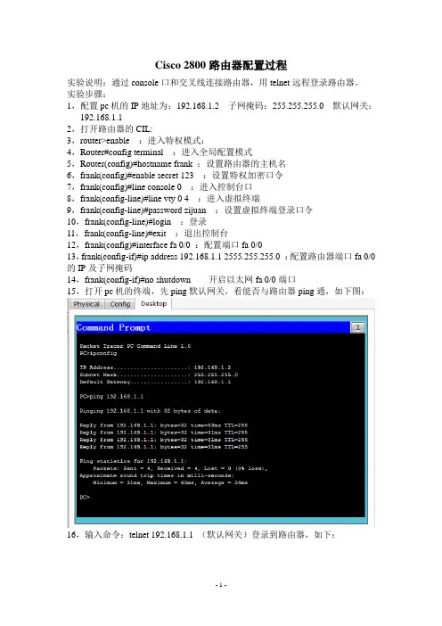
9,frank(config-line)#password zijuan :设置虚拟终端登录口令
10,frank(config-line)#login :登录
11,frank(config-line)#exit :退出控制台
12,frank(config)#interface fa 0/0 :配置端口fa 0/0
13,frank(config-if)#ip address 192.168.1.1 2555.255.255.0 :配置路由器端口fa 0/0的IP及子网掩码
14,frank(config-if)#no shutdown 开启以太网fa 0/0端口
15,打开pc机的终端,先ping默认网关,看能否与路由器ping通,如下图:
16,输入命令:telnet 192.168.1.1 (默认网关)登录到路由器,如下:。


思科 Aironet 系列 2800/3800 无线接入点部署指南首次发布日期: 2016年05月11日Americas HeadquartersCisco Systems, Inc.170 West Tasman DriveSan Jose, CA 95134-1706USATel: 408 526-4000800 553-NETS (6387)Fax: 408 527-0883本手册中有关产品的规格和信息如有更改,恕不另行通知。
本手册中的所有声明、信息和建议均准确可靠,但我们不为其提供任何明示或暗示的担保。
用户必须承担使用产品的全部责任。
随附产品的软件许可和有限担保在随产品一起提供的信息包中提供,且构成本文的一部分。
如果您无法找到软件许可或有限担保,请与思科代表联系以获取副本。
思科所采用的TCP报头压缩是加州大学伯克利分校(UCB)开发的一个程序的改版,是UCB的UNIX操作系统公共域版本的一部分。
保留所有权利。
版权所有©1981,加州大学董事会。
无论本手册中是否有任何其他保证,这些供应商的所有文档文件和软件均按“原样”提供,并可能包含缺陷。
思科和上面所提及的提供商拒绝所有明示或暗示担保,包括(但不限于)适销性、特定用途适用性和无侵权担保,或者因买卖或使用以及商业惯例所引发的担保。
在任何情况下,对于任何间接、特殊、连带发生或偶发的损坏,包括(但不限于)因使用或无法使用本手册而导致的任何利润损失或数据损失或损坏,思科及其供应商概不负责,即使思科及其供应商已获知此类损坏的可能性也不例外。
本文档中使用的任何互联网协议(IP)地址和电话号码并非实际地址和电话号码。
本文档中所含的任何示例、命令显示输出、网络拓扑图和其他图形仅供说明之用。
说明性内容中用到的任何实际IP地址或电话号码纯属巧合,并非有意使用。
思科和思科徽标是思科和/或其附属公司在美国和其他国家/地区的商标或注册商标。
要查看思科商标列表,请访问此网址:/go/trademarks。
C i s c o2800系列重设路由密码解决方法(总2页)-CAL-FENGHAI.-(YICAI)-Company One1-CAL-本页仅作为文档封面,使用请直接删除Cisco 2800系列重设路由密码解决方法1、必需先用终端方式接C**OLE口,进入终端状态;2、开路由器电源;3、在60秒内,按Ctrl +Break键,中断路由器的启动进程,使其进入ROM监控模式,提示符为”rommon >”或者”>”;4、在ROM监控模式下,通过confreg命令修改配置寄存器的值,使路由器忽略NVRAM中的启动配置文件。
一般路由器缺省的配置寄存器值为 0×2102,我们将配置寄存器的值修改为 0×2142,使路由器在启动时不再加载NVRAM中的启动配置文件。
如下所示:rommon 1 >confreg 0×21425、在ROM监控模式下,输入reset命令使路由器重新启动。
如下所示:rommon 2 > reset6、重启后路由器不再加载NVRAM中的启动配置文件,而是进入系统配置对话模式。
出现的提示按下Ctrl+C或输入no 退出即可。
7、这时路由器进入用户EXEC模式。
直接键入 enable 命令即可进入特权EXEC 模式。
如下所示:router >enablerouter#8、手工将NVRAM中的启动配置文件复制到RAM中,成为当前的配置文件。
这时可以查看当前配置文件,获得口令。
命令如下:router#copy startup-config running-config9、复制完成之后,设置用户名和密码, 命令如下:router(config)#username 你的用户名 password 你的密码当你正常启动路由器后,输入这个用户名和密码才能进入下一步配置。
10、设置配置模式下的密码,并将当前的配置文件保存到NVRAM中。
命令如下:router#configure terminalrouter(config)#enable secret ciscorouter(config)#exitrouter#copy running-config startup-config11、恢复配置寄存器的值,在全局配置模式下将配置寄存器的值改回 0×2102。

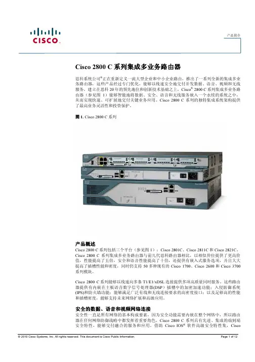
Cisco 2800系列集成多业务路由器常见问题问:什么是Cisco® 2800 系列集成多业务路由器?答: Cisco 2800 系列由四个新平台组成:Cisco 2801、Cisco 2811、 Cisco 2821和 Cisco 2851路由器。
Cisco 2800 系列与前几代思科路由器相比,以相似的价位提供了极高的价值,它的机箱性能提高了五倍,安全和话音性能提高了十倍,添加了新的内嵌服务选项,并大大提高了插槽性能和密度,同时支持90多种现有Cisco 1700 系列、 2600 系列、3700 系列和3800 系列接口卡及模块中的大多数。
Cisco 2800 系列可快速、高质量地同时提供多种服务。
Cisco 2800 系列不仅提供内嵌加密加速和主板话音数字信号处理器 (DSP)插槽;入侵保护和防火墙功能;集成化呼叫处理和语音留言;适用于多种连接要求的高密度接口;而且也具有充足的性能和插槽发展空间,可满足未来网络扩展需求和运行先进应用。
Cisco 2800 系列架构是同类产品中的最佳架构,专为满足中小型企业、中小型企业分支机构和服务供应商可管理服务应用对于并发服务的需求而设计,且不会影响路由器性能。
问:思科系统公司® 为什么推出 Cisco 2800 系列?答:思科之所以推出 Cisco 2800 系列,是为了在不影响路由器性能的情况下,部署以线速运行的多种集成服务。
集成多业务路由器系列经过了专门设计,在一个集成路由平台中同时运行多种具优秀性能的服务,如话音、安全、服务质量(QoS)和其他路由服务等。
问: Cisco 2800 系列中有哪些版本?答: Cisco 2800 系列包括Cisco 2801、 Cisco 2811、 Cisco 2821和 Cisco 2851。
Cisco 2811、2821和 2851共享单一网络模块插槽、4个高密度 WIC (HWIC)插槽和 2 个高级集成模块 (AIM)插槽。

《Cisco 2801路由器》用户配置手册约定在介绍重要的术语和概念时,或许以粗体显示。
正文所包含的命令以常体显示,用于实例的所有名称或地址亦是这样,同时不应该用到你的实际网络中。
配置你的系统时不要一字不差地输入名称或地址。
最后,在某些例子中,在命令要求IP地址作为参数的地方,IP地址可能以xx.xx.xx.xx或.dd这种方式来表示。
实际上,配置你的系统时永远不会用到这些字符串。
本文的约定指出你应该把指明的地方替换成适当的IP地址。
1.本文档覆盖的东西有好几种方法可用来配置Cisco路由器。
配置可以由TFTP服务器通过网络来完成;可以通过启动时提供的菜单界面来完成;并且可以由运行setup命令所提供的菜单界面来完成;还可以由保存到内存中的配置来完成。
本手册不会覆盖这几种方法,它仅覆盖由IOS命令行界面来进行的配置。
注意:本手册不覆盖路由器与它要路由的网络在物理上的连接,它仅覆盖操作系统配置。
1.1使用命令行的原因使用命令行界面而不使用菜单驱动界面的原因有两个:一个是速度。
一旦你已花费时间去了解命令行命令,就可以比通过使用菜单更加迅速地完成许多操作。
基本上,相对于菜单的所有命令行来说,这点是真的。
对于了解Cisco IOS的命令行界面来说它是特别有效的东西,而Cisco IOS是跨越一切Cisco路由器的标准。
其次,可以配置单个接口而不必中断其它接口上的服务。
根据定义,路由器有多个接口。
例如,在 Cisco 7200系列路由器中,路由器有多个端口,每个端口有几个可热插拔模块。
这些模块能够经由命令行来单独配置是一种颇有价值的技术。
1.2 文档结构本文的第一部分将介绍IOS的命令模式和Cisco路由器基本配置所必需的命令。
文档的第二部分将在个案研究里示范这些命令的用法。
个案研究是由本文作者完成的实际配置。
2.准备开始初时,你或许会通过终端来配置你的路由器。
如果路由器已经配置过,而且至少一个端口已经用IP地址配置好,同时它与网络有物理连接的话,你也许能够telnet到路由器,通过网络来配置它。
In-Sight®2800Series Reference Manual2022April26Revision:22.1.1.127Legal NoticesThe software described in this document is furnished under license,and may be used or copied only in accordance with the terms of such license and with the inclusion of the copyright notice shown on this page.Neither the software,this document,nor any copies thereof may be provided to,or otherwise made available to,anyone other than the licensee. Title to,and ownership of,this software remains with Cognex Corporation or its licensor.Cognex Corporation assumes no responsibility for the use or reliability of its software on equipment that is not supplied by Cognex Corporation. Cognex Corporation makes no warranties,either express or implied,regarding the described software,its merchantability,non-infringement or its fitness for any particular purpose.The information in this document is subject to change without notice and should not be construed as a commitment by Cognex Corporation.Cognex Corporation is not responsible for any errors that may be present in either this document or the associated software.Companies,names,and data used in examples herein are fictitious unless otherwise noted.No part of this document may be reproduced or transmitted in any form or by any means,electronic or mechanical,for any purpose,nor transferred to any other media or language without the written permission of Cognex Corporation.Copyright©2022.Cognex Corporation.All Rights Reserved.Portions of the hardware and software provided by Cognex may be covered by one or more U.S.and foreign patents,as well as pending U.S.and foreign patents listed on the Cognex web site at:/patents.The following are registered trademarks of Cognex Corporation:Cognex,2DMAX,Advantage,AlignPlus,Assemblyplus,Check it with Checker,Checker,Cognex Vision for Industry, Cognex VSOC,CVL,DataMan,DisplayInspect,DVT,EasyBuilder,Hotbars,IDMax,In-Sight,Laser Killer,MVS-8000, OmniView,PatFind,PatFlex,PatInspect,PatMax,PatQuick,SensorView,SmartView,SmartAdvisor,SmartLearn, UltraLight,Vision Solutions,VisionPro,VisionViewThe following are trademarks of Cognex Corporation:The Cognex logo,1DMax,3D-Locate,3DMax,BGAII,CheckPoint,Cognex VSoC,CVC-1000,FFD,iLearn,In-Sight (design insignia with cross-hairs),In-Sight 2000,InspectEdge,Inspection Designer,MVS,NotchMax,OCRMax,PatMax RedLine,ProofRead,SmartSync,ProfilePlus,SmartDisplay,SmartSystem,SMD4,VisiFlex,XpandPortions copyright©Microsoft Corporation.All rights reserved.Portions copyright©MadCap Software,Inc.All rights reserved.Other product and company trademarks identified herein are the trademarks of their respective owners.SymbolsThe following symbols indicate safety precautions and supplementalinformation:WARNING:This symbol indicates a hazard that could cause death,serious personal injury or electricalshock.CAUTION:This symbol indicates a hazard that could result in property damage.Table of ContentsLegal Notices2Symbols3 Table of Contents4Getting Started6 About the In-Sight2800Series6 Illumination Options for In-Sight28007 Accessories8 Lenses8 Illumination8 Lens Covers10 Mounting Brackets11 Cables12 Support12 Setting Up Your In-Sight Vision System13 Vision System Layout13 Dimensions14 In-Sight2800Mini with6.2mm lens14 In-Sight2800Mini with16mm Lens15 In-Sight2800with Multi Torch16 In-Sight2800Mini with6.2mm Lens-Right Angle Configuration17 In-Sight2800Mini with16mm Lens-Right Angle Configuration18 In-Sight2800with Multi Torch-Right Angle Configuration19 Field of View and Working Distance20 In-Sight2800with Multi Torch and12mm Lens20 In-Sight2800with Multi Torch and16mm lens21 In-Sight2800Mini with6.2mm Lens22 In-Sight2800Mini with16mm Lens23 Installing and Changing Lenses24 Installing Manual Lens on Multi Torch24 Changing Front Cover on Multi Torch30 Connecting the Vision System32 Mounting the Vision System33 Connecting the Ethernet Cable34 Connecting the Power and I/O Breakout Cable35 Indicator LEDs35 Using Your In-Sight Vision System36 Installing In-Sight Vision Suite36 Trigger Types37 Industrial Protocols38 Specifications39 In-Sight2800Series Vision System39 In-Sight2800Series Vision System Image Sensor39 LED and Laser Wavelengths41 Acquisition Trigger Input41High-Speed Outputs42 High Speed Output Wiring43 Ethernet Cable44 Power and I/O Breakout Cable Specifications44 CCB-PWRIO-0545Cleaning and Maintenance46 Clean the Housing46 Clean the Vision System Image Sensor Window46 Clean the Vision System Lens Cover46Regulations and Conformity47中国大陆RoHS(Information for China RoHS Compliance)48 For European Community Users48Getting StartedThis section provides general information about the In-Sight2800series vision system and the accessories and systems.About the In-Sight2800SeriesThe In-Sight2800series vision systems are high-performance,easy hardware and software setup vision systems that offer:l Premium class performance in a compact packagel Flexible Industry4.0connectivity optionsl Unmatched Modularity and Ease of Useresolutionsl 1.6mp mono color and SVGA monoIllumination Options for In-Sight2800The following illumination options are available for In-Sight2800vision systems:l Multi Torch:The Multi Torch is a high-powered integrated multi-color light module with RED,GREEN,BLUE,andWHITE colors in a single package.The Multi Torch is compatible with vision system using12or16mm lens.l High Powered Illumination for16mm lens:High-powered integrated light attachments are available in RED or WHITE color options for In-Sight2800Mini vision systems using a16mm lens.l Standard Illumination for6.2mm lens:Integrated light attachments are available in RED,WHITE,BLUE,or IR options for In-Sight2800Mini vision systems using a6.2mm lens.AccessoriesYou can purchase the following components separately.For a list of options and accessories,contact your local Cognex sales representative.LensesIlluminationIllustration CAUTION:280-TORCH-MULTI devices equipped with a target aimer have been tested in accordance withIEC60825-13rd ed.,2014.,and have been certified to be under the limits of a Class2Laser device.Lens CoversCAUTION:For280-TORCH-COVPOL,280-TORCH-COVCLR,and280-TORCH-COVDIF equipped with a Time-of-Flight sensor,the device has been tested to be under the limits of a Class1Laser device.Mounting BracketsCablesSupportMany information resources are available to help you use the vision system: l The EasyBuilder Help file,provided with the In-Sight software.l On-demand training:/on-demand-training.aspx.l The In-Sight online support site:/support/insight.Setting Up Your In-Sight Vision SystemRead this section to learn how the vision system connects to its standard components and accessories.CAUTION:All cable connectors are keyed to fit the connectors on the vision system.Do not force the connectionsor damage may occur.Vision System LayoutThe image and table below shows the elements of the vision system.Number DescriptionPower I/O Breakout cable connectorEthernet connectorIllumination LEDsTrigger buttonNote:The Trigger Button is not supported.Tune buttonNote:The Tune Button is not supported.Indicator LEDsPower LED indicatorTrain status/Trigger status LED indicatorGood/bad inspection LED indicatorCommunication LED indicatorError LED indicatorDimensionsThe following sections list dimensions of the vision system.In-Sight2800Mini with6.2mm lensThe following image shows the dimensions of In-Sight2800,equipped with6.2mm lens.In-Sight2800Mini with16mm LensThe following image shows the dimensions of In-Sight2800equipped with16mm lens.In-Sight2800with Multi TorchThe following image shows the dimensions of In-Sight2800equipped with Multi Torch.The following image shows the dimensions of In-Sight2800equipped with L-shaped extension and6.2mm lens.The following image shows the dimensions of In-Sight2800equipped with L-shaped extension and16mm lens.In-Sight2800with Multi Torch-Right Angle ConfigurationThe following image shows the dimensions of In-Sight2800equipped with L-Shaped extension and Multi Torch.Field of View and Working DistanceThis section discusses the Field of View values for the IS2800with Multi Torch and IS2800Mini configurations.(On the diagrams,the values at the top are in mm and the values at the bottom of the top values in the brackets are in inch).In-Sight2800with Multi Torch and12mm LensIn-Sight2800with Multi Torch and16mm lensInstalling and Changing LensesThis section provides an overview about installing and changing different kinds of lenses.l Installing Manual Lens on Multi Torch on page 24l Changing Front Cover on Multi Torch on page 30CAUTION:Perform all lens modification procedures in a dust-free and ESD safe area.Installing Manual Lens on Multi Torch1.Screw in the four screws from the adapter into the front of the housing.2.Install the manual lens subassembly to the unit.a.Push the six pins into the designated holes of the adapter and align the cylindrical flange to the center ofthe unit.b.Tighten the the M2x5mm HSH screw halfway,then tighten the M2x12mm HSH screw halfway as well.Continue screwing each screw incrementally,until tightening them to0.4Nm,using a torque wrench.3.Screw in the four screws from the adapter into the back of the light module housing.4.Screw in the four screws from the light module into the front cover.Changing Front Cover on Multi Torch1.Unscrew the four screws from the light module,then take off the front cover from the light module.2.Attach the new front cover and screw in the four screws into the front cover.Connecting the Vision SystemMounting the Vision System on page 33Connecting the Ethernet Cable on page 34Connecting the Power and I/O Breakout Cable onMounting the Vision SystemThe vision system provides mounting holes for attachment to a mounting surface.CAUTION:The vision system has to be grounded,either by mounting the vision system to a fixture that iselectrically grounded or by attaching a wire from the vision system’s mounting fixture to frame ground or Earthground.If a ground wire is used,it has to be attached to one of the four mounting points on the back plate of the vision system and not to the mounting points on the front of the vision system.Align the holes on the mounting surface with the mounting holes on the vision system.Insert the M3X3.5screws into the mounting holes.Connecting the Ethernet CableCAUTION:The Ethernet cable shield has to be grounded at the far end.Whatever this cable is plugged into (typically a switch or router)should have a grounded Ethernet connector.A digital voltmeter has to be used tovalidate the grounding.If the far end device is not grounded,a ground wire should be added in compliance with local electrical codes.1.Connect the Ethernet cable's M12connector to the vision system ENET connector.2.Connect the Ethernet cable’s RJ-45connector to a switch/router or PC,as applicable.Connecting the Power and I/O Breakout CableCAUTION:To reduce emissions,connect the far end of the Breakout cable shield to frame ground.1.Verify that the24VDC power supply is unplugged and not receiving power.2.Attach the Power and I/O Breakout cable's+24VDC and Ground wires to the corresponding terminals on thepower supply.For more information,see Specifications on page 39.3.Attach the Power and I/O Breakout Cable's M12connector to the vision system's24VDC connector.4.Restore power to the24VDC power supply and turn it on if necessary.Indicator LEDsThe table summarizes the functions of the In-Sight2800's indicator LEDs.Using Your In-Sight Vision SystemThis section provides information on the installation of the In-Sight,troubleshooting connection issues,tuning,image filtering,as well as vision system training and package detection.Installing In-Sight Vision SuiteFollow the steps below to install and connect your vision system to the In-Sight Vision Suite.1.Download the latest version of In-Sight Vision Suite from /and follow the on-screen steps.2.Connect the2800series vision system to your PC.unch In-Sight Vision Suite and click Refresh.4.Select a vision system from the list and click Connect.Trigger TypesThe In-Sight2800vision systems support the following trigger modes.l Self:At a time interval you configure,the vision system acquires an image and runs the job on said image automatically.l Single(external trigger):Acquires a single image and runs the current job on the acquired image.The vision system relies on an external trigger source.Industrial ProtocolsThe vision system supports the following industrial protocols:l EtherNet/IP™,EDS and PLCl PROFINET(Class B)l SLMP Protocoll TCP/IPl OPC/UAl FTPFor more information see Industrial Communications in In-Sight documentation.SpecificationsThe following sections list general specifications for the vision system.In-Sight2800Series Vision SystemIn-Sight2800Series Vision System Image SensorLED and Laser WavelengthsThe following table shows LED types and the related peak wavelengths.Acquisition Trigger InputThe vision system features one acquisition trigger input,which is optically isolated.You can configure the acquisition trigger input to trigger from an NPN(current sinking)or PNP(current sourcing)device.l To trigger from an NPN type photoelectric sensor or PLC output,connect COMMON IN to+24VDC and connect IN0to the output of the photoelectric sensor.When the output turns ON,it pulls TRIGGER down to0VDC,turning the opto-coupler ON.l To trigger from a PNP photoelectric sensor or PLC output,connect IN0to the output of the photoelectric sensor and connect COMMON IN to0VDC.When the output turns ON,it pulls TRIGGER up to+24VDC,turning theopto-coupler ON.Number InputIN0High-Speed OutputsFor NPN lines,the external load should be connected between the output and the positive supply voltage(<26VDC). The output pulls down to less than3VDC when ON,which causes current to flow through the load.When the output is OFF,no current flows through the load.Number OutputNPN OUTFor PNP lines,the external load should be connected between the output and the negative supply voltage(0VDC). When connected to a24VDC power supply,the output pulls up greater than21VDC when ON,and current flows through the load.When the output is OFF,no current flows through the load.Number OutputCOMMON OUTHigh Speed Output WiringTo connect to an NPN-compatible PLC input,connect one of the vision system's high-speed outputs directly to the PLC input.When enabled,the output pulls the PLC input down to less than3VDC.To connect to a PNP-compatible PLC input,connect one of the vision system's high-speed outputs directly to the PLC input.When enabled,the output pulls the PLC input up to greater than21VDC.To connect the high-speed outputs to a relay,LED or similar load,connect the negative side of the load to the output and the positive side to+24VDC.When the output switches on,the negative side of the load is pulled down to less than3 VDC,and21VDC appears across the e a protection diode for a large inductive load,with the anode connected to the output and the cathode connected to+24VDC.Ethernet CableThe Ethernet cable provides Ethernet connectivity to the vision system.The Ethernet cable is used to connect the vision system to other network devices.Number Wire Color Signal Name P2Pin NumberWhite/Orange TxRx A+1Orange TxRx A-2White/Green TxRx B+3Blue TxRx C+8White/Blue TxRx C-7Green TxRx B-4White/Brown TxRx D+5Brown TxRx D-6CAUTION:The Ethernet cable shield has to be grounded at the far end.Whatever this cable is plugged into (typically a switch or router)should have a grounded Ethernet connector.A digital voltmeter has to be used tovalidate the grounding.If the far end device is not grounded,a ground wire should be added in compliance with local electrical codes.Cables are sold separately.The wiring for this cable follows standard industrial Ethernet M12specifications.It differs from thestandard.Power and I/O Breakout Cable SpecificationsCCB-PWRIO-05The Power and I/O Breakout cable provides access to trigger and high-speed outputs.For RS-232,use the Power Supply return path for ground.The figure on the left shows the plug on the device.Pin#Signal Names WireOut2/In2YellowTxD White/YellowRxD BrownOut3/In3White/BrownIn1VioletCommon In White/Violet+24VDC RedGND BlackCommon Out GreenIn0OrangeOut0BlueOut1Greyare sold separately.wiring or adjustments to I/O devices when the vision system is not receiving power.cut exposed wires short or trim wire ends.You also can tie the wires back if you use non-conductive material.Keep bare wires separated from the+24VDC wire.Cleaning and MaintenanceClean the HousingTo clean the outside of the vision system housing,use a small amount of mild detergent cleaner or isopropyl alcohol ona cleaning cloth.Do not pour the cleaner on the vision systemhousing.CAUTION:Do not attempt to clean any In-Sight product with harsh or corrosive solvents,including lye,methyl ethyl ketone(MEK)or gasoline.Clean the Vision System Image Sensor WindowTo remove dust from the outside of the image sensor window,use a pressurized air duster.The air must be free of oil, moisture or other contaminants that could remain on the glass and possibly degrade the image.Do not touch the glass window.If oil or smudges remain,use a cotton bud and alcohol(ethyl,methyl,or isopropyl)to clean the window.Do not pour the alcohol on the window.Clean the Vision System Lens CoverTo remove dust from the lens cover,use a pressurized air duster.The air must be free of oil,moisture or other contaminants that could remain on the lens cover.To clean the plastic window of the lens cover,use a small amount of isopropyl alcohol on a cleaning cloth.Do not scratch the plastic window.Do not pour the alcohol on the plastic window.Regulations and ConformityIn-Sight vision systems have Regulatory Model numbers50208,50210,50215,50216and meet or exceed the requirements of all applicable standards organizations for safe operation.However,as with any electrical equipment,the best way to ensure safe operation is to operate them according to the agency guidelines that follow.Please read these guidelines carefully before using your device.EUTÜVUK中国大陆RoHS (Information for China RoHS Compliance)根据中国大陆《电子信息产品污染控制管理办法》( 也称为中国大陆RoHS),以下部份列出了本产品中可能包含的有毒有害物质或元素的名称和含量。
Cisco 2800系列Cisco 2800系列集成多业务路由器提供了更高的性能、更高的安全性和语音性能、全新内嵌服务选项,以及更高的插槽性能和密度。
它保留了对Cisco 1700系列和Cisco 2600系列路由器大多数现有接口卡和模块的支持。
它由4个新的平台组成:Cisco 2801、Cisco2811、Cisco 2821和Cisco 2851,能够在多个T1/E1/xDSL连接上以线速提供多项高质量同步服务。
适用场合销售该产品当客户需要下列特性时Cisco 2800 需出色性能和密度,以便能在多个T1/E1/xDSL连接上并发提供数据、安全、语音和高级服务具有VPN连接,或计划后续迁移到该连接集成安全服务可实现网络设备保护、威胁防御、安全连接,以及终端保护和控制需安全的集成呼叫处理、语音留言、灵活的电话接口、针对集中呼叫处理的冗余性,或强大的DSP支持,包括本地会议和自动语音编码转换功能通过集成的IEEE 802.11 a/b/g接入点HWIC提供无线支持在从4端口到48端口的各种密度的产品中集成了第二层交换功能,且能使用Cisco StackWise连接关键特性模块化架构——拥有广泛的局域网和广域网选择。
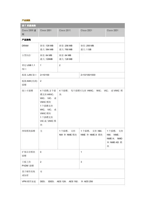
网络接口能够现场升级以采用未来的技术;拥有若干类型的插槽,可根据“随发展随集成”的模式,在未来添加连接和服务内嵌安全硬件加速——内嵌硬件加密加速器,与可选的Cisco IOS软件升级配合,有助于实现广域网链路的安全和支持VPN服务集成双快速以太网或千兆以太网端口——在Cisco 2801和Cisco 2811上提供了2个10/100以太网端口,在Cisco 2821和Cisco 2851上提供了2个10/100/1000以太网端口配备增强功能的HWIC插槽,包括无线局域网接入点;双AIM插槽;母板上的分组语音DSP模块(PVDM)插槽IP语音解决方案是一个一体化V oIP解决方案,配备了Cisco Call Manager Express、语音接口和Cisco Unity Express,提供语音留言和自动接听功能基于硬件的板载加密功能,用于DES、3DES和AES,以及用于PVDM的板载插槽,它们都拥有高速以太网接口支持可选的专用安全AIMEzVPN通过从单一头端向远程站点推出新的安全策略,简化了点到点VPN管理DSP模块为模拟和数字语音、会议、自动语音编码转换和安全的实时传输协议(RTP)应用提供了支持网络准入控制(NAC)——这是一种思科自防御网络机制,通过只允许符合要求和可信任的终端设备接入网络,极大地提高了网络识别、防御和适应攻击的能力用于PoE配电的可选集成电源实时时钟支持竞争对手产品Juniper: J 系列3Com: SuperStack II NETBuilder SI 和Pathbuilder S400, 5000 & 6000 系列Intel/Shiva: LanRover系列Motorola: Vanguard 645x/643x Nortel/Bay: Advanced Remote Node (ARN), Passport 4400 系列Tasman: 2004, 1400Huawei: AR2800产品特性特性Cisco 2801 Cisco 2811 Cisco 2821 Cisco 2851固定的USB1.1端口1个2个与Cisco 2811相同与Cisco 2811相同板载局域网端口2个10/100 与Cisco 2801相同2个10/100/1000 与Cisco 2821相同板载AIM(内部)插槽2个与Cisco 2801相同与Cisco 2801相同与Cisco 2801相同接口卡插槽4个插槽;2个插槽支持HWIC、WIC、VIC或VWIC类型的模块1个插槽支持WIC、VIC或VWIC类型的模块1个插槽支持VIC或VWIC类型的模块4个插槽,每个插槽都支持HWIC、WIC、VIC或VWIC类型的模块网络模块插槽没有1个插槽,支持NM和NME类型的模块1个插槽,支持NM、NME和NME-X类型的模块1个插槽,支持NM、NME、NME-X和NME-XD类型的模块扩展语音模块插槽0与Cisco 2801相同1个与Cisco 2821相同母板上的PVDM(DSP)插槽2个与Cisco 2801相同3个与Cisco 2821相同集成基于硬件的加密有与Cisco 2801相同与Cisco 2801相同与Cisco 2801相同可选的PoE 有,需要AC-IP系统电源与Cisco 2801相同与Cisco 2801相同与Cisco 2801相同控制台端口(高达115.2kbps)1个与Cisco 2801相同与Cisco 2801相同与Cisco 2801相同辅助端口(高达115.2kbps)1个与Cisco 2801相同与Cisco 2801相同与Cisco 2801相同最低Cisco IOS软件版本12.3(8)T4 与Cisco 2801相同与Cisco 2801相同与Cisco 2801相同机架安装有,19英寸有,19和23英寸两种与Cisco 2811相同与Cisco 2811相同墙壁安装没有有与Cisco 2811相同与Cisco 2811相同交流输入电压100-240V AC 与Cisco 2801相同与Cisco 2801相同与Cisco 2801相同交流输入频率47-63Hz 与Cisco 2801相同与Cisco 2801相同与Cisco 2801相同交流输入电流2A(110V),1A(230V)与Cisco 2801相同3A(110V);2A(230V)与Cisco 2821相同交流输入浪涌电流最大50A,一个周期(包括-48V电压)与Cisco 2801相同与Cisco 2801相同与Cisco 2801相同交流IP最大馈线配电120W 160W 240W 360W交流IP输入电流4A (110V); 2A (230V) 与Cisco 2801相同8A (110V); 4A(230V)与Cisco 2821相同交流IP输入浪涌电流最大50A,一个周期(包括-48V电压)与Cisco 2801相同与Cisco 2801相同与Cisco 2801相同直流输入电压没有直流电源选项24-60VDC,自动调节正反向与Cisco 2811相同与Cisco 2811相同直流输入电流没有直流电源选项8A(24V)3A(60V)启动电流5A<10ms 12A(24V)5A(60V)启动电流50A<10ms与Cisco 2821相同功耗——交流交流,,没有PoE支持150W(511BTU/hr)170W(580BTU/hr)280W(955BTU/hr)与Cisco 2821相同功耗——交流交流,,带PoE-IP电话支持180W (612 BTU/hr.) 160W (546 BTU/hr.) 240W (819 BTU/hr.) 与Cisco 2821相同功耗——直流不适用180W(614BTU/hr)300W(1024BTU/hr)与Cisco 2821相同冗余电源支持(RPS)没有仅限于外部,缺省提供RPS连接器与Cisco 2811相同与Cisco 2811相同推荐RPS 设备没有RPS 选项Cisco RPS-675冗余电源系统与Cisco 2811相同 与Cisco 2811相同工作温度 32-104°F ;(0-40℃) 与Cisco 2801相同 与Cisco 2801相同 与Cisco 2801相同 工作湿度 10-85%非冷凝 5-95%非冷凝与Cisco 2811相同与Cisco 2811相同 非工作温度N/A-4-149℉(-20-65℃) 与Cisco 2811相同与Cisco 2811相同规格规格((高x 宽x 长)1.72x17.5x16.5英寸(43.7x445x419毫米)1.75x17.25x16.4英寸(44.5x438.2x416.6毫米)3.5x17.25x16.4英寸(88.9x438.2x416.6毫米)与Cisco 2821相同 机架高度1个机架单元(1RU )1个机架单元(1RU ) 2RU 与Cisco 2821相同 重量重量((配置后配置后))13.7磅(6.2公斤) 14磅(6.4公斤)25磅(11.4公斤)与Cisco 2821相同噪音级别(最小/最大最大))39dBA ,正常工作温度(<90/32.3℉℃)53.5dBA (最高风扇速度)47dBA ,正常工作温度(<90/32.3℉℃) 57dBA (最高风扇速度)44dBA ,正常工作温度(<90/32.3℉℃) 53dBA (最高风扇速度)安全 UL 60950CAN/CSA C22.2 No.60950 IEC 60950 EN 60950-1 AS/NZS 60950与Cisco 2801相同 与Cisco 2801相同 与Cisco 2801相同抗干扰性 EN300386 EN55024/CISPR24 EN50082-1 EN6100-6-2与Cisco 2801相同 与Cisco 2801相同 与Cisco 2801相同EMCFCC Part 15;ICES-003 Class A;EN55022 Class A;CISPR22 Class A;AS/NZS 3548 Class A;VCCI Class A EN 300386;EN61000-3-3;EN61000-3-2TELCOM 视国家和接口类型的不同,遵循相应的电信标准。
可以参考以下指令完成:1.进入特权模式Router>enable2.进入全局配置模式Router#configure termial3.设置路由器的主机名,{name}为你需要修改的路由器的名称Router(config)#hostname {name}4.设置路由器的加密口令,{password}为你需要创建的口令Router(config)#enable secret {passwor}5.进入接口配置模式Router(config)#interface {interface-type} solt/number{interface-type}为接口类型,它们可以是serial、fastethernet、loopback 等等solt/number为接口的模块号和接口号举例,如果你要进入Fastethernet0号模块的0号接口的配置模式则输入Router(config)#interface fastethernet 0/06.为接口分配IP地址和掩码,ABCD为你要分配的IP地址和掩码Router(config-if)#ip address A.B.C.D A.B.C.D7.启用接口Router(config-if)#no shutdown8.配置静态路由Router(config)#ip route x.x.x.x x.x.x.x {next-hop-address} {interface} x.x.x.x x.x.x.x为你指定的目的地的网络地址{next-hop-address}为到达该目的地下一跳路由器的接口IP地址,该地址必须可达{interface}为到达该目的地的本地出站接口举例1,如果你指定路由器到达目的地192.168.1.0/24网络的下一跳地址为10.1.1.1,则配置如下:Router(config)#ip route 192.168.1.0 255.255.255.0 10.1.1.1举例2,如果你指定路由器到达目的地192.168.1.0/24网络的本地出站接口为Fastethernet 0/0,则配置如下:Router(config)#ip route 192.168.1.0 255.255.255.0 fastethernet 0/0 9.配置路由选择协议Router(config)#router {routing-protocols}Router(config-router)#network x.x.x.x{routing-protocols}为你希望启用的IP路由选择协议network x.x.x.x为你希望在哪些接口或者网络启用该路由选择协议举例,你希望配置OSPF路由选择协议,并希望在192.168.1.0网络的接口上启用OSPF,同时将该网络划分到OSPF区域0中。
配置接口特性这一章详细说明交换机上的接口和描述怎么配置他们。
这章有以下这些内容:●理解接口类型●使用接口命令●配置二层接口●监控和维护第二层接口●配置第三从接口注意:需要完整的有关该章的语法和应用信息,请参考Catalyst 3550 Multilayer Switch Command Reference和Cisco IOS Interface Command Referencefor Release 12.1.理解接口类型这个部分描述了不同的接口类型,以及其它章节所包括的详细配置这些接口的一些参考内容。
其他章节描述了物理接口特性的配置过程。
这部分包括:•基于端口的VLAN (Port-Based VLANs)•交换端口(Switch Ports)•以太网通道端口组(EtherChannel Port Groups)•交换虚拟接口(Switch Virtual Interfaces)•被路由端口(Routed Ports)•连接接口(Connecting Interfaces)基于端口的VLAN (Port-based Vlans)一个Vlan是一个按功能、组、或者应用被逻辑分段的交换网络,并不考虑使用者的物理位置。
要更多关于Vlan的信息请看“Configuring VLANS”。
一个端口上接受到的包被发往属于同一个Vlan的接收端口。
没有一个第三层的设备路由Vlan间的流量,不同Vlan的网络设备无法通讯。
为了配置普通范围(Normal-range) Vlan(Vlan IDs 1-1005),使用命令:config-vlan模式(global) vlan vlan-id或vlan-configuration模式(exec) vlan database针对Vlan ID 1-1005的vlan-configration模式被保存在vlan数据库中。
为配置扩展范围(extended-range) Vlans (Vlan ID 1006-4094),你必须使用config-vlan模式,并把VTP的模式设为transparent透明模式。
思科路由器配置教程思科路由器是一种常见的网络设备,用于连接多个网络和设备,实现互联网的接入和共享。
想要正确地配置思科路由器,需要清楚了解路由器的基本知识和配置步骤。
下面是思科路由器配置的详细教程,帮助您正确地配置和管理路由器。
第一步,连接路由器。
将路由器的电源适配器插入电源插座,并连接路由器的WAN口(广域网口)与宽带调制解调器的LAN口(局域网口)通过以太网线相连。
然后,使用另一根以太网线将路由器的LAN口与计算机相连。
第二步,登录路由器。
打开您的计算机上的任一网页浏览器,输入路由器的默认管理地址(一般为192.168.1.1)并按下回车键。
系统将要求输入用户名和密码。
根据路由器型号,输入相应的用户名和密码(默认情况下用户名为admin,密码为空或admin)。
第三步,检查和修改路由器的基本配置。
在登录成功后,您将进入路由器的配置页面。
在该页面上,您可以查看和修改路由器的各项基本配置,如无线网络名称(SSID)、无线密码以及管理密码等。
请根据自己的需求进行相应的修改,并将新的配置保存。
第四步,配置互联网连接方式。
根据您的网络服务提供商的要求,选择适当的互联网连接类型。
一般情况下,可以选择DHCP自动获取IP地址。
如果您的网络需要静态IP地址,请选择PPPoE,并输入提供商提供的用户名和密码等相关信息。
第五步,设置路由器的无线网络。
在无线设置页面上,您可以配置无线网络的名称(SSID)、加密方式和密码等。
建议启用WPA2加密方式,并设置足够复杂的无线密码以提高网络安全性。
点击保存按钮,使设置生效。
第六步,配置网络地址转换(NAT)。
在NAT设置页面上,您可以配置路由器的NAT功能,用于将局域网内部的IP地址转换成全球唯一的公网IP地址。
默认情况下,路由器会自动启用NAT功能,一般不需要进行额外的设置。
第七步,配置端口转发(Port Forwarding)。
如果您需要在局域网内访问外部网络中的服务器,可以通过端口转发功能实现。
《Cisco 2801路由器》用户配置手册
约定
在介绍重要的术语和概念时,或许以粗体显示。
正文所包含的命令以常体显示,用于实例的所有名称或地址亦是这样,同时不应该用到你的实际网络中。
配置你的系统时不要一字不差地输入名称或地址。
最后,在某些例子中,在命令要求IP地址作为参数的地方,IP地址可能以xx.xx.xx.xx或.dd这种方式来表示。
实际上,配置你的系统时永远不会用到这些字符串。
本文的约定指出你应该把指明的地方替换成适当的IP地址。
1.本文档覆盖的东西有好几种方法可用来配置Cisco路由器。
配置可以由TFTP服务器通过网络来完成;可以通过启动时提供的菜单界面来完成;并且可以由运行setup命令所提供的菜单界面来完成;还可以由保存到内存中的配置来完成。
本手册不会覆盖这几种方法,它仅覆盖由IOS命令行界面来进行的配置。
注意:本手册不覆盖路由器与它要路由的网络在物理上的连接,它仅覆盖操作系统配置。
1.1使用命令行的原因使用命令行界面而不使用菜单驱动界面的原因有两个:
一个是速度。
一旦你已花费时间去了解命令行命令,就可以比通过使用菜单更加迅速地完成许多操作。
基本上,相对于菜单的所有命令行来说,这点是真的。
对于了解Cisco IOS的命令行界面来说它是特别有效的东西,而Cisco IOS是跨越一切Cisco路由器的标准。
其次,可以配置单个接口而不必中断其它接口上的服务。
根据定义,路由器有多个接口。
例如,在 Cisco 7200系列路由器中,路由器有多个端口,每个端口有几个可热插拔模块。
这些模块能够经由命令行来单独配置是一种颇有价值的技术。
1.2 文档结构本文的第一部分将介绍IOS的命令模式和Cisco路由器基本配置所必需的命令。
文档的第二部分将在个案研究里示范这些命令的用法。
个案研究是由本文作者完成的实际配置。
2.准备开始初时,你或许会通过终端来配置你的路由器。
如果路由器已经配置过,而且至少一个端口已经用IP地址配置好,同时它与网络有物理连接的话,你也许能够telnet到路由器,通过网络来配置它。
如果路由器未曾做过配置,那么你将不得不用终端和一条串口电缆直接和它连接。
对于任何一台Windows主机来说,你都可以用超级终端(Hyperterminal)容易地连接路由器。
把串口电缆插入PC机上的串口(COM),另一端插入Cisco路由器上的控制台端口。
启动超级终端,告诉它所用的COM 口并点击OK。
把连接速率设置为9600波特,点击OK。
如果路由器未开机,启动它。
如果你想由Linux主机来配置路由器,要运行Seyon或Minicom。
至少它们中的一个,也许两个都在你的Linux分发套件中。
通常,你需要敲Enter(回车)键来观看路由器所作的提示。
如果路由器未做过配置,它看起来象这样:
Cisco2801>
Cisco2801 为主机名称原始名称为(Router)为了更好的管理和使用特更改为(Cisco2801)
你要配置路由器就必须进入特权模式。
你可以通过使用enable命令来做到这点。
特权模式通常是口令保护,除非路由器未配置好。
你有无口令保护特权模式的选择,但极力推荐你选择有口令保护的特权模式。
在你运行命令enable并提供口令之后,你就会进入特权模式。
为了帮助用户看清所处的模式,每次进入不同的模式,命令行的提示都会发生改变。
当你从非特权模式切换到特权模式时,提示由:
Cisco2801>
变成
Cisco2801#
配置实例
用超级终端连接到到Cisco设备上
输入登陆密码
Passwrod:
Cisco2801>
Cisco2801>enable
输入特权密码
Passwrod:
Cisco2801#
Cisco2801#config t
cisco2801(config)#
配置模式
cisco2801(config)#int fa0/0
对fa0/0进行设置
cisco2801(config-if)#
子端口设置模式
Cisco2801(config-if)# ip nat outside
转换IP包的源,这些IP包正在从外部传输到内部
转换IP包的目的地,这些IP包正在从内部传输到外部
cisco2801(config-if)#ip add .dd x.x.x.x
.dd 为运营商所提供的IP地址
x.x.x.x 为运营商所提供的子网掩码
cisco2801(config-if)# no shut
激活端口
Cisco2801(config-if)#end
退出子端口设置
注:以上是对外网端口设置说明
cisco2801#config t
配置模式
cisco2801(config)# int fa0/1
对fa0/1进行设置
cisco2801(config-if)#ip nat inside
转换IP包的源,这些IP包正在从内部传输到外部
转换IP包的目的地,这些IP包正在从外部传输到内部
cisco2801(config-if)#ip add 192.168.1.1 255.255.255.0
设置内网IP地址
cisco2801(config-if)#no shut
激活端口
cisco2801(config-if)#end
注:以上是对内网端口设置说明
cisco2801#config t
进入配置模式
cisco2801(config)#access-list 1 permit any
建立访问列表
cisco2801(config)#ip nat inside source list 1 int fa0/0 overload
就是在路由上不设置地址池,因为只有一个公网地址,而只对fa0/0接口的地址超载。
注意:一条NAT转换条目要占用160字节内存,因此NAT的转换数目受路由器的内存限制。
cisco2801(config)#ip route 0.0.0.0 0.0.0.0 x.x.x.x x.x.x.x为网络运营上提供的网关
cisco2801(config)#end
退出配置模式
cisco2801#wr
保存配置信息。