HP 小型机日常维护介绍
- 格式:ppt
- 大小:868.50 KB
- 文档页数:61
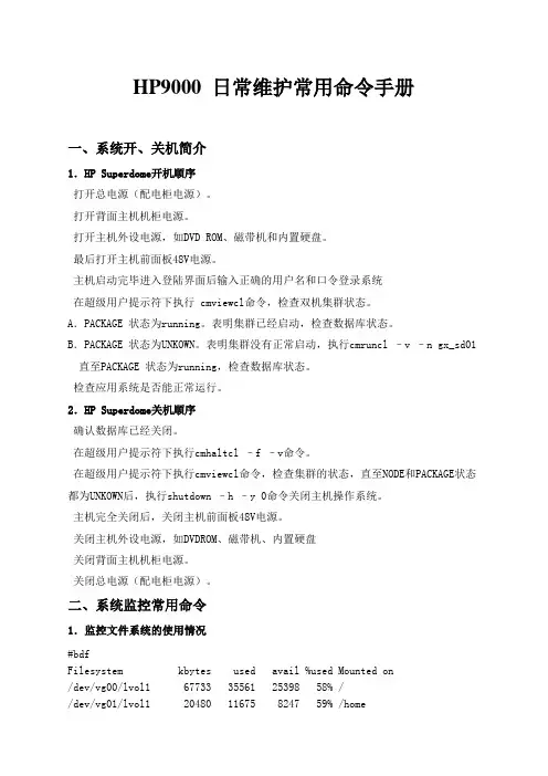
HP9000 日常维护常用命令手册一、系统开、关机简介1.HP Superdome开机顺序打开总电源(配电柜电源)。
打开背面主机机柜电源。
打开主机外设电源,如DVD ROM、磁带机和内置硬盘。
最后打开主机前面板48V电源。
主机启动完毕进入登陆界面后输入正确的用户名和口令登录系统在超级用户提示符下执行 cmviewcl命令,检查双机集群状态。
A.PACKAGE 状态为running。
表明集群已经启动,检查数据库状态。
B.PACKAGE 状态为UNKOWN。
表明集群没有正常启动,执行cmruncl –v –n gx_sd01直至PACKAGE 状态为running,检查数据库状态。
检查应用系统是否能正常运行。
2.HP Superdome关机顺序确认数据库已经关闭。
在超级用户提示符下执行cmhaltcl –f –v命令。
在超级用户提示符下执行cmviewcl命令,检查集群的状态,直至NODE和PACKAGE状态都为UNKOWN后,执行shutdown –h –y 0命令关闭主机操作系统。
主机完全关闭后,关闭主机前面板48V电源。
关闭主机外设电源,如DVDROM、磁带机、内置硬盘关闭背面主机机柜电源。
关闭总电源(配电柜电源)。
二、系统监控常用命令1.监控文件系统的使用情况#bdfFilesystem kbytes used avail %used Mounted on/dev/vg00/lvol1 67733 35561 25398 58% //dev/vg01/lvol1 20480 11675 8247 59% /home各列的含义:Filesystem:文件系统名kbytes:字节数,以k为单位used:已使用空间avail:尚可使用空间%used: 已使用空间占本文件系统全部空间比率。
Mounted on: 安装目录在下列两种情况下,系统管理员应考虑做必要的文件清理工作:%used达到90%以上时avail显示字节数较小时(如小于10K)2.日志文件的监控常用日志文件/var/adm/syslog/ 系统运行日志。
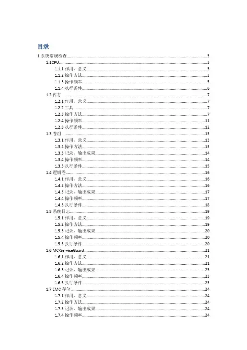
目录1.系统常规检查 (3)1.1CPU (3)1.1.1作用、意义 (3)1.1.2操作方法 (3)1.1.3操作频率 (5)1.1.4执行条件 (5)1.2内存 (6)1.2.1作用、意义 (6)1.2.2工具 (6)1.2.3操作方法 (6)1.2.4操作频率 (10)1.2.5执行条件 (11)1.3卷组 (12)1.3.1作用、意义 (12)1.3.2操作方法 (12)1.3.3记录、输出成果 (13)1.3.4操作频率 (13)1.3.5执行条件 (14)1.4逻辑卷 (15)1.4.1作用、意义 (15)1.4.2操作方法 (15)1.4.3记录、输出成果 (16)1.4.4操作频率 (16)1.4.5执行条件 (17)1.5系统日志 (18)1.5.1作用、意义 (18)1.5.2操作方法 (18)1.5.3记录、输出成果 (19)1.5.4操作频率 (19)1.5.5执行条件 (19)1.6 MC/ServiceGuard (20)1.6.1作用、意义 (20)1.6.2操作方法 (20)1.6.3记录、输出成果 (22)1.6.4操作频率 (22)1.6.5执行条件 (22)1.7 EMC存储 (23)1.7.1作用、意义 (23)1.7.2操作方法 (23)1.7.3记录、输出成果 (23)1.7.4操作频率 (23)1.7.5执行条件 (24)2.突发事件检查 (25)2.1检查日志 (25)2.1.1作用、意义 (25)2.1.2操作方法 (25)2.1.3记录、输出成果 (25)2.1.4操作频率 (25)2.1.5执行条件 (25)2.2主机性能检查 (26)2.2.1作用、意义 (26)2.2.2操作方法 (26)2.2.3记录、输出成果 (28)2.2.4操作频率 (28)2.2.5执行条件 (28)1.系统常规检查1.1CPU监控主机CPU利用率1.1.1作用、意义对核心各HP主机系统的CPU利用率进行检查,检验其是否对系统性能造成影响。
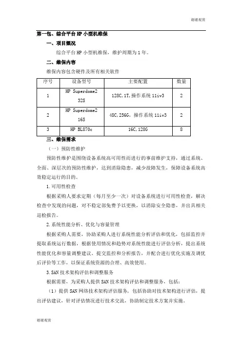
第一包、综合平台HP小型机维保一、项目慨况综合平台HP小型机维保,维护周期为1年。
二、维保内容维保内容包含硬件及所有相关软件(一)预防性维护预防性维护是围绕设备系统高可用性而进行的事前维护支持,通过系统、全面、深层次的预防性维护,达到消除隐患,减少故障发生,保障设备系统高效稳定运行的目的。
1.可用性检查根据采购人要求定期(每月至少一次)对设备系统进行可用性检查,解决检查中发现的问题,对不稳定部免费予以更换,以消除安全隐患,并出具相关巡检报告。
2.系统性能分析、优化与容量管理根据采购人需要,协助采购人进行系统性能分析评估和优化,包括监控并提取系统运行数据,根据使用情况和趋势对系统性能进行评估分析,提出系统性能优化和容量调整建议,提交监控和分析报告,并配合进行优化实施及调优后评价等工作,以保证系统资源的合理、高效使用。
3.SAN技术架构评估和调整服务根据需要,为采购人提供SAN技术架构评估和调整服务,包括:(1)提供SAN网络技术架构评估服务, 包括协助对技术架构进行评估,提出评估建议,针对评估情况进行技术交流,协助制定技术方案并实施。
(2)根据不同时期的环境配置需求协助采购人对系统进行必要的调整变更,根据采购人的架构调整需求,提出调整建议,协助制定技术方案并对实施工作提供技术支持。
评估和调整建议需具有可实施性和有效性。
★4、硬件微码和软件版本升级服务需协助采购人对设备系统微码和软件版本进行管理和升级,包括:协助制定维护策略与流程;定期核查分析产品版本情况,及时提供服务范围内所有产品的升级信息(包括微码、各种补丁、PATCH、PTF等),保证采购人能够及时获取并使用,保证其合法性、准确性和及时性;提供升级风险分析,根据采购人的环境配置情况,分析版本升级对系统及应用的影响,提交产品版本升级建议,协助制定升级方案,对升级的测试、实施等工作提供技术支持。
在升级过程中,如遇到异常情况能获得后台的支持,对于已升级产品如遇特殊需求可使用工具进行回退。
HP小型机巡检表小型机巡检表HP(Hewlett-Packard)小型机是一种在中小型企业中广泛使用的服务器,它承担着重要的业务功能。
为了确保HP小型机的稳定运行,提高工作效率,定期进行巡检是非常必要的。
下面是HP小型机巡检表,具体内容如下:1. 硬件巡检:- 检查服务器是否正常启动,CPU和内存使用率是否正常。
- 检查硬盘空间是否充足,如果不够,请及时清理或增加硬盘。
- 检查硬盘是否存在故障或预测失败,如果有,需要进行故障排除或更换硬盘。
- 检查服务器的风扇和散热器是否正常运转,以防止过热造成的故障。
- 检查服务器的电源和电缆连接是否良好,确保供电稳定。
2. 操作系统巡检:- 检查操作系统是否有安全漏洞,及时进行补丁更新。
- 检查病毒防护软件是否正常运行,病毒库是否及时更新。
- 检查操作系统日志,查看是否存在异常事件。
- 检查防火墙设置,确保服务器的安全性。
3. 数据库巡检:- 检查数据库是否正常运行,检查数据库的连接情况。
- 检查数据库日志,查看是否存在异常事件。
- 检查数据库备份,确保备份的完成和可恢复性。
4. 网络巡检:- 检查网络设备是否正常工作,如交换机、路由器等。
- 检查网络连接是否稳定,网络延迟是否过高。
- 检查网络防火墙设置,确保网络安全。
5. 应用程序巡检:- 检查应用程序是否正常运行,包括Web服务器、邮件服务器等。
- 检查应用程序日志,查看是否存在异常事件。
- 检查应用程序的数据备份,确保数据的完整性。
6. 安全巡检:- 检查服务器的访问权限,确保只有授权人员能够访问。
- 检查密码策略,确保密码的安全性。
- 检查服务器的入侵检测系统,确保服务器的安全。
7. 性能巡检:- 检查服务器的性能指标,如CPU使用率、内存使用率、磁盘I/O等。
- 检查服务器的网络带宽使用情况,以及网络延迟情况。
- 检查服务器的响应时间,确保用户体验良好。
通过定期进行以上巡检,可以确保HP小型机的正常运行,及时发现并解决潜在问题,提高工作效率。
日常维护一.CD/DVD ROM的使用在把CD或DVD放入驱动器后,需要进行一些操作才能够使用。
这些操作是让CD-ROM或DVD-ROM成为HP-UX文件系统的一部分。
具体操作步骤如下:1. 确定一个mount点,假设是'/SD_CDROM'2. 确定CD-ROM的硬件路径(设备文件名,可用命令'ioscan -fnkC disk'获得)假设是'/dev/dsk/c2t2d0'3. 将CD-ROM驱动器用'mount'命令mount到mount点,使其成为HP-UX文件系统的一部分。
命令格式# mount /dev/dsk/c2t2d0 /SD_CDROM4. 然后,就可以进到该目录下去读取CD-ROM上的内容了。
二.磁带机的使用与维护1- Tape drive door2- 磁带状态灯3- 清洗/ 提示灯4- 弹出按钮特点(1) SE SCSI-2接口(2) 未压缩数据容量:可读写DDS-1, DDS-2, DDS-3 格式的磁带60米磁带-DDS-1=1.3Gbytes90米磁带-DDS-1=2.0Gbytes120米磁带-DDS-2=4.0Gbytes当采用压缩方式时,上述数据容量将提高2到4倍(3) 1Mbytes 数据Buffer(4) 通过On-board Switch 或者程序可以将磁带机设置为DCLZ数据压缩格式。
(5) 同步数据传送率=3.0 Mbytes异步数据传送率=7.5 Mbytes(6) Power On 时,将进行自检磁带机使用注意事项(1) 磁带使用的寿命次数:100次左右(2) 磁带机清洗带的使用频率:次数/ 每天清洗间隔3 每周4 隔天5 隔天>;=4 每天(3) 强制性退出磁带:当按动“退出”按钮35秒后,磁带仍未退出,那么按住“退出”按钮至少5秒钟,可以强制性退出磁带。
磁带机设备文件命名简介一些设备命名例子和意义:/dev/rmt/c1t3d0BEST BEST = "highest density possible"/dev/rmt/c1t3d0sQIC150nb QIC-150 format, no rewind on close, Berkeley/dev/rmt/c1t3d0D8MM8500C (Names can be quite descriptive)/dev/rmt/0m (For compatibility with the past)The components of "/dev/rmt/c1t0d0BESTnb" mean:dev = device filermt = raw magnetic tapec1 = the device is connected to interface card instance 1t0 = the target device address is set to 0d0 = the tape transport resides at unit address 0,BEST = the tape will be written using the best available density/format(meaning "pack as much onto this tape as is possible"n = the tape will not be rewound on closeb = the device will have Berkeley-style behavior三.HP modem的使用原则当惠普工程师完成安装后会交给用户一个Modem。
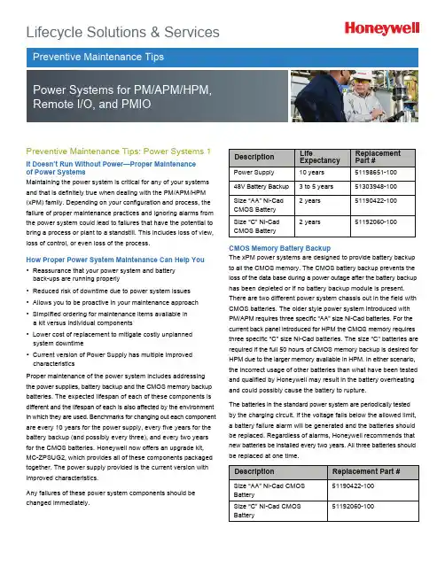
Lifecycle Solutions & ServicesPreventive Maintenance Tips: Power Systems 1It Doesn’t Run Without Power—Proper Maintenance of Power SystemsMaintaining the power system is critical for any of your systems and that is definitely true when dealing with the PM/APM/HPM (xPM) family. Depending on your configuration and process, the failure of proper maintenance practices and ignoring alarms from the power system could lead to failures that have the potential to bring a process or plant to a standstill. This includes loss of view, loss of control, or even loss of the process.How Proper Power System Maintenance Can Help You• Reassurance that your power system and battery back-ups are running properly • Reduced risk of downtime due to power system issues • Allows you to be proactive in your maintenance approach • Simplified ordering for maintenance items available in a kit versus individual components • Lower cost of replacement to mitigate costly unplanned system downtime• Current version of Power Supply has multiple improved characteristicsProper maintenance of the power system includes addressing the power supplies, battery backup and the CMOS memory backup batteries. The expected lifespan of each of these components is different and the lifespan of each is also affected by the environment in which they are used. Benchmarks for changing out each component are every 10 years for the power supply, every five years for the battery backup (and possibly every three), and every two years for the CMOS batteries. Honeywell now offers an upgrade kit, MC-ZPSUG2, which provides all of these components packaged together. The power supply provided is the current version with improved characteristics.Any failures of these power system components should be changed immediately.DescriptionLifeExpectancyReplacement Part #Power Supply 10 years 51198651-100 48V Battery Backup 3 to 5 years 51303948-100 Size “AA” Ni-Cad CMOS Battery 2 years 51190422-100 Size “C” Ni-Cad CMOS Battery2 years51192060-100CMOS Memory Battery BackupThe xPM power systems are designed to provide battery backup to all the CMOS memory. The CMOS battery backup prevents the loss of the data base during a power outage after the battery backup has been depleted or if no battery backup module is present. There are two different power system chassis out in the field with CMOS batteries. The older style power system introduced with PM/APM requires three specific “AA” size Ni-Cad batteries. For the current back panel introduced for HPM the CMOS memory requires three specific “C” size Ni-Cad batteries. The size “C” batteries are required if the full 50 hours of CMOS memory backup is desired for HPM due to the larger memory available in HPM. In either scenario, the incorrect usage of other batteries than what have been tested and qualified by Honeywell may result in the battery overheating and could possibly cause the battery to rupture.The batteries in the standard power system are periodically tested by the charging circuit. If the voltage falls below the allowed limit, a battery failure alarm will be generated and the batteries should be replaced. Regardless of alarms, Honeywell recommends that new batteries be installed every two years. All three batteries should be replaced at one time.DescriptionReplacement Part #Size “AA” Ni-Cad CMOS Battery51190422-100 Size “C” Ni-Cad CMOS Battery 51192060-100Preventive Maintenance Tips: Power Systems 2 48 Volt Battery BackupThe battery backup is designed to maintain a fully loaded xPM fora minimum of 20 minutes. It will shutdown when the voltage reaches38 volts to prevent the power supply from going out of regulation and an alarm will be generated. Rechargeable batteries will lose their full charging capabilities over time and will need to be tested and replaced when they fall below 60 percent of their original capacity.The battery backup has been designed to operate in standby (float) service for approximately five years. The five years is based on the battery being kept at 20C (68F) and the float charge voltage being maintained between 2.25 and 2.30 volts per cell. This includes the battery being fully discharged once every three months. No battery should be left in service over five years, and if no maintenance is done it should be replaced every three years.The service life is directly affected by the number of discharges, the depth of discharge, ambient temperature, and the charging voltage. The expected service life can be shorted by 20% for each 10C that the ambient is above 20C.The batteries should never be left in a discharged state. This allows sulfating to occur which will increase the internal resistance of the battery and lower its capacity. The self-discharge rate is about 3% per month at an ambient of 20C. The self discharge rate doubles for each 10C in ambient above 20C. The discharged voltage of the battery should never go below 1.30 volts to maintain the best battery life.With this in mind it is recommended to periodically load test the batteries to ensure they have sufficient capacity to maintain the system during a power outage. Tests should be done on an annual basis and more frequently as they become older and begin to lose capacity. The load test is recommended off-process if possible as there will be no battery backup available while performing the test and recharging of the battery pack can take up to 16 hours. Having a spare available to swap, especially if doing on process, is a wise option leading to minimal time without battery backup and allowing the tested battery to be recharged on a bench outside the system for future swap with the next test.If regular maintenance is not performed the recommendation is to change at least every three years rather than every five.Power SuppliesThe power supply is the heart of the xPM power system and the recommendation is for a redundant power supply configuration having each power supply fed by its own dedicated power source. Honeywell has introduced the next generation power supply for this family which increases the robustness of the power system. Even with redundant power supplies, one must be careful when changing out a failed power supply. This is to minimize disturbance of the environment and to reduce the introduction of particles into the area around and near the power supplies. Those particles can be pulled through the airflow of the working power supply and result in the second power supply failing.For this reason, Honeywell does not recommend replacing a working power supply on-process (other than the black-colored version). However, power supplies do not last forever and you should consider upgrading older power supplies, or prepare to do so, when the opportunities arise.The recommendation for changing out the power supplies is every ten years and this replacement should be included during a scheduled down time if possible. The power supply replacement procedure listed in the Honeywell xPM Service manual should be followed at all times.Recommend Change of Original Black Power SuppliesIn October of 1996 Honeywell issued a customer priority notification (PN #1986) about a possible over-voltage issue with the black-colored (51109456-200) power supplies that were sold from 1988 through 1994. The Honeywell recommendation was to change out those black power supplies with the new silver version. Honeywell still recommends and strongly suggest that these black power supplies be replaced with the current power supply under part number 51198651-100 regardless of when they were put into service.Silver Power SuppliesThere have been three part number versions of the silver power supplies. The first (51109684-100/300) was sold from 1993 through 1997. The second (51198947-100) sold from 1997 through today. The next generation power supply was released in early 2009 and was introduced initially through the power system maintenance upgrade kit. If a site is running the original silver version they have now been in service for over 10 years and sites should consider the need to replace before they are forced to do so by failure of the power supply. Note that there is always risk involved when powering down equipment and possible issues when the equipment is powered back up. As stated previously, it is recommended to change these out off-process if possible. Replacements on- process should be done only when a power supply fails and replacement is then required immediately.Description Replacement Part #48V Battery Backup51303948-100Preventive Maintenance Tips: Power Systems 3Power Supply IssuesThe xPM power supplies have proven to be a reliable and robust power source. However, as with any electrical component they do not last forever and there is the potential for failure modes. Issues such as foreign particles introduced have already been discussed. In addition, even clean environments are susceptible to whiskers which have the potential to short out active circuits. Whiskers are a real issue and further details may be found in the Customer Resource Manual (CRM) in the Process Manager section PD22_G97(G).The new power supply available through the power system maintenance kit includes design improvements specifically done to address some of these possible failure modes to make a robust power supply even better.Remember that the power supply is a critical component to your system and regular maintenance as well as having spares available is highly recommended to keep your site running without problems. Monitor the power system alarms and take action when they do occur.DescriptionReplacement Part #Power Supply51198651-100Preventive Maintenance Tips: Power Systems 4Importance of Power System AlarmsAlways ensure that all power supply alarm contacts are properly implemented, working, and are being monitored. Failure to monitor these alarms and take appropriate action in a timely manner can lead to failures of the power system that could have otherwise been prevented. There are DC Out, Battery, Fan/Temp, AC In, and Charging LED indicators for each Power Supply module. If the Power system is fully functional, all five of the indicators are illuminated. In addition, each of these conditions, plus a CMOS/Memory is available as a digital input for each supply.DC Out IndicatorIf a DC Out LED is off, AC line power has been lost (check the AC In LED) or the Power Supply Module has failed. If the Power System is non-redundant, or if both DC Out LEDs are off, the HPM has lost 24 VDC. The CMOS backup system maintains power to the CMOS memory, so subsystem programs are not lost. See the Battery LED description below. The annunciator contact illustrated in the following figure will open when these conditions occur.Battery IndicatorIf the Battery LED is off and the Charging LED is on, the 48 Volt Battery switch is in the off position or the 48 V Battery Backup system has failed. The annunciator contact illustrated in the following Figure will open when these conditions occur. If the Power System does not have the battery pack option, the Battery LED will normally be on, and the Charging LED will normally be on.Fan/Temp IndicatorIf the Fan/Temp LED is off, the fan in the Power Supply Module has failed or the temperature of the supply has exceeded a safe value. The annunciator contact, discussed below, is activated.AC In IndicatorIf the AC In LED is off, AC power to the HPM has been lost or the switch on the Power Supply Module is off. Backup systems, if operating, are maintaining the unit. Check the DC Out and Battery indicators to determine the state of the system. Many installations may have the Power Supply Modules connected to separate AC power sources to minimize outage caused by a power loss. The Annunciator contact signifying power loss from either supply, are opened independently.Charging IndicatorWhen the Charging LED is off, the charging circuit that maintains the optional 48 V Battery Backup system has failed. Check the batteries, their corresponding connections, and the charging circuits in the Power Supply Module(s). The annunciator contact output is opened by this condition.For More InformationLearn more about how Honeywell’s Preventive Maintenance Tips can limit downtime and assure system power supplies and battery backups are working properly visit our website or contact your Honeywell account manager. Honeywell Process Solutions Honeywell1250 West Sam Houston Parkway South Houston, TX 77042Honeywell House, Arlington Business Park Bracknell, Berkshire, England RG12 1EB Shanghai City Centre, 100 Junyi Road Shanghai, China 20051 AlarmsThe primary Power Supply Module alarm and secondary Power Supply Module alarm contacts monitor five functions within each Power Supply Module. The appropriate contact will open when any of the following occur:• The DC output voltage is not within normal limits. • AC input power to the supply has failed.• The Power Supply Module electronics have overheated or the Power Supply Module fan has failed. • The 48 V backup-battery system has failed because the batteries have discharged or they have been disconnected. • The battery charger in the Power Supply Module has failed.Servicing the Power SystemThe power system is critical to your process. Loss of the power system may lead to loss of control, loss of view, or loss of process. Honeywell strongly recommends regular maintenance to the power system and service checks with regular component replacements performed by Honeywell trained service technicians. • Options for Power System Upgrade/Maintenance • Order the power system upgrade kit• Order replacement parts for immediate installation. • Order spares to have in stock as needed.• Add power system components to a parts contract.Preventive Maintenance Tips: Power Systems 5Orderable Power System Components• CMOS Batteries • 48V Battery Backup • Power Supply• Power System Chassis AssemblyBenefits of New Power Supply• Improved airflow handling• Conformal coating of all metallic components • Enhanced mechanical design • Extended temperature range • Added thermal shutdown capability • More reliable power switch design • More consistent alarm handlingAdditional Power System InformationAdditional details on proper maintenance procedures such as load testing and specifics on the power supplies and batteries may be found in the Honeywell Customer Resource Manual. This is located in the Process Manager section of the CRM under TAB 22. As always, you may also contact your local Honeywell account manager or service technician for further details.SV-12-37-ENG May 2012© 2012 Honeywell International Inc.。
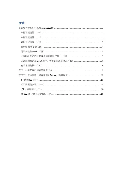
目录安装惠普瘦客户机系统xpe wes2009 (2)如何下载镜像(一) (2)如何下载镜像(二) (2)如何下载镜像(三) (3)刷新镜像至U盘(四) (4)更改参数加-y –xb (五) (5)U盘启动做完之后把U盘插到瘦客户机上(六) (5)机器启动默认是USER用户,切换到管理员模式(七) (6)安装常用的软件(八) (6)方法一:抓配置好的系统镜像(九) (9)方法二:快速部署(建议使用)Rdeploy 抓取镜像 (12)IE7降到IE6(十) (15)打印机驱动安装(十一) (15)USB U盘控制(十二) (18)给User用户赋予右键权限(十三) (19)安装惠普瘦客户机系统xpe wes2009如何下载镜像(一)登录找到驱动程序软件下载,在产品名称型号输入瘦客户机的型号,例如:T5740 或者vc4820如何下载镜像(二)选择要下载的语音(中文选择简体中文)和要下载的系统。
如何下载镜像(三)下载的程序是.exe格式()刷新镜像至U盘(四)把U盘查到电脑上,面是往U盘里写程序,同时做U盘启动。
选择U盘的盘符U盘里面的东西,释放完之后的。
更改参数加-y –xb(五)进入\UFD\IBRPE用记事本编辑THINSTATE.CMD还下面一样。
在\FLASH.IBR 前面添加-Y -XB@ECHO OFFCLSCOLOR 17\IBRPE\IBRPE.EXE–Y –XB \FLASH.IBR HD0U盘启动做完之后把U盘插到瘦客户机上(六)要进行HP ThinState部署,请执行以下操作:1. 将F10 系统BIOS 中的引导顺序设为USB boot(USB 引导)。
2. 将USB 闪存驱动器连接到您要部署捕获映像的瘦客户机设备,然后打开该设备。
3. 按照屏幕中的说明执行操作。
当您拔下USB 闪存驱动器并重启系统电源后,映像将解包。
此过程需要3–5 分钟,具体取决于闪存驱动器速度和内部闪存大小。
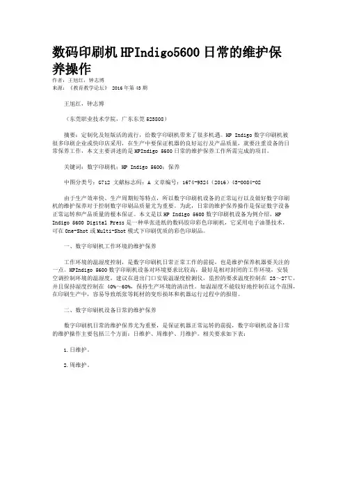
数码印刷机HPIndigo5600日常的维护保养操作作者:王旭红,钟志博来源:《教育教学论坛》 2016年第43期王旭红,钟志博(东莞职业技术学院,广东东莞523808)摘要:定制化及短版活的流行,给数字印刷机带来了很多机遇。
HP Indigo数字印刷机被很多印刷企业或快印店采用,在生产中要保证机器的良好运行及产品质量,就要注重设备的日常保养工作,本文主要讲述的是HPIndigo 5600日常的维护保养工作所需完成的项目。
关键词:数字印刷机;HP Indigo 5600;保养中图分类号:G712 文献标志码:A 文章编号:1674-9324(2016)43-0084-02由于生产效率快、生产周期短等特点,所以数字印刷机设备的正常运行以及做好数字印刷机的维护保养对于控制数字印刷品质量尤为重要。
为此,日常的维护保养操作是保证数字设备正常运转和产品质量的根本保证。
本文是以HP Indigo 5600数字印刷机设备为例介绍,HP Indigo 5600 Digital Press是一种单张进纸的数码胶印彩色印刷机,它采用电子油墨技术,可在One-Shot或Multi-Shot模式下印刷优质的彩色印刷品。
一、数字印刷机工作环境的维护保养工作环境的温湿度控制,是数字印刷机日常正常工作的前提,也是维护保养机器要关注的一点。
HPIndigo 5600数字印刷机设备对环境要求比较高,最好是相对封闭的工作环境,安装空调控制环境的温湿度,建议在进出门口安装温湿度检测仪,监控的要求温度控制在23~27℃,并且保持湿度控制在40%~60%,保持生产环境的清洁性。
如温湿度不能较好地控制在这个范围,在印刷生产中,容易导致纸张等耗材的变形损坏和机器运行过程中的报错。
二、数字印刷机设备日常的维护保养数字印刷机日常的维护保养尤为重要,是保证机器正常运转的前提,数字印刷机设备日常的维护操作主要包括三个方面:日维护、周维护、月维护。
相关要求如下表:1.日维护。
HP MC/SG日常管理操作太极计算机股份有限公司2008/02目录1.管理Cluster和Package (3)2.日常操作系统备份 (4)1.基本管理Cluster和Package管理Cluster和节点1)启动Cluster# cmruncl -v# cmruncl -v -n node1 -n node22)在已运行的Cluster中增加一个节点运行# cmrunnode -v node23)在已运行的Cluster中停止一个节点运行# cmhaltnode -f -v node24)停止整个Cluster# cmhaltcl -f -v5)对Cluster进行重新配置停止整个Cluster如果要改变CLUSTER LOCK VG,则 # vgchange -c n vg01# vgchange -a y vg01重新进行配置工作cmapplyconfcmruncl管理Package和Service1)启动Package# cmrunpkg -n node1 pkg1# cmmodpkg -e node1 pkg1 //把切换属性置为yes.故障发生后//可以自动切换。
//要注意2)停止Package,不切换# cmhaltpkg pkg13)移动Package# cmhaltpkg pkg1 -n node1# cmrunpkg -n node2 pkg1# cmmodpkg -e pkg1 //让package可以切换4)对Package进行重新配置停止整个Cluster修改配置文件修改control.sh文件(注意保证所有节点一致)cmapplyconfcmruncl4)查看运行情况# cmviewcl -v2.日常操作系统备份make_tape_recovery可以创建一个能自启的磁带镜像,包括在root卷集中有选择的关键的文件和目录。
如果root卷集中的任何磁盘坏了,可以用磁带恢复到一个最小的系统,从磁带启动将会完成下面几项:1,在root盘重建启动区2,在vg00里的磁盘上重建逻辑卷和文件系统3,恢复已选择的关键文件和目录到root盘前提条件1,确保安装了Ignite-UXmake_tape_recovery是Ignite-UX的一个部分,在HP-UX的标准安装中没有捆绑,需要用户自定义安装。
文章简介HP Deskjet F2128 一体机没有液晶显示屏,所以必须通过面板上各个灯的闪烁情况来确定状态。
本文介绍了这款一体机 LED 灯闪烁时,所代表的一体机状态,以及发生故障时简单的解决方法。
解决方法配合按钮面板上指示灯闪烁地状态,点击以下链接解决问题:全部显示| 全部隐藏“开/关机”指示灯不停地闪烁图 1: 工作状态现象描述现象一执行某些操作后,“开/关机”指示灯不停地闪烁现象二一体机连接电源线以后,没有做任何操作,但是开/关机指示灯不停地闪烁可能原因及解决办法:● 现象一:一体机正在工作,如打印、扫描、复印过程中。
● 现象二:一体机开机后就只有电源指示灯不停闪烁,且断开 ✞ 连接线后,并多次重新启动均无法恢复开 关机指示灯常亮的待机状态,则说明一体机存在硬件故障,例如内部的线路脱落等。
遇到这种情况请送至维修中心检测。
检查纸张的红灯闪烁现象描述检查纸张的红灯闪烁。
可能原因● 缺纸● 卡纸解决方法● 缺纸 :● 如果在执行打印或复印操作时,恰巧纸盒里没纸,可以重新放好纸张后,按❽启动 重新开始❾按钮继续打印。
如果无法打印,请参考以下文档,清除中断的打印任务,然后重新打印:如何清除无法删除的打印任务?● 如果纸盒里有纸,但是一体机却不能正常将纸盒中的纸张卷入。
此时请确认纸张的厚度、大小和放置位置,然后重新测试。
如果您的一体机已经使用了较长的时间或者平时工作量较大。
可以打开纸张检测门,使用湿布清洁橡胶滚轮,通过加大卷纸轮的摩擦力来解决此故障。
● 卡纸 :请参考以下文章解决卡纸问题:一体机出现卡纸情况后,如何正确的取出卡纸?检查墨盒的红灯闪烁现象描述检查墨盒的红灯闪烁。
可能原因● 一体机前方的墨盒检测门处于打开状态。
● 两个墨盒至少有一个没有安装或者没有安装到位。
● 至少一个墨盒没墨、墨盒超过保质期、墨盒损坏、自行灌墨所造成墨盒无法被识别。
● 安装的墨盒型号不对。
● 一体机的固件(♐♓❒❍♦♋❒♏)发生故障,不能正常识别墨盒。
P740小型机日常维护手册目录一. 设备环境介绍二. 系统操作三. 巡检操作四. 常用操作五. 日常事务六. 常用命令一. 设备环境介绍设备型号:IBM P740 8205-E6C设备功能介绍:本项目为:全省操作风险管理系统工程,小型机主要承担授权数据库与事后监督数据库稳定运行与备份的任务。
其中两台小型机采用互为备份方式:设备拓扑简介:设备连接介绍:每个地市数据中心采用 2 台 IBM Power 740 小型机服务器运行数据库系统,分别运行HACMP 软件,配置成双机互备系统,保证系统的高可靠性。
2 台 IBM Power 740 分别通过 2 根光纤连接到 2 台存储光纤交换机,2 台磁盘阵列通过 2 根光纤连接到 2 台存储光纤交换机,如此连接即保证了可靠性,又提高了数据访问的效率。
设备磁盘管控:小型机 1 主机名为:tyxxdb1, (HMC 管理 IP 为 1.1.1.5)自身拥有 IP 10.0.31.1, 默认提供数据库名为 TYSQDB 的服务服务 IP 为 10.0.31.3 默认挂载磁盘/tysqdbdata 和 /rmansq小型机 2 主机名为:tyxxdb2, (HMC 管理 IP 为 1.1.1.6)自身拥有 IP 10.0.31.2, 默认提供数据库名为 TYSQDB 的服务服务 IP 为 10.0.31.4 默认挂载磁盘/tyhddbdata 和 /rmanhd挂载的磁盘/tysqdbdata 分配空间为: 750G/rmansq 分配空间为: 875G挂载的磁盘/tyhddbdata 分配空间为: 1150G/rmanhd 分配空间为: 1275G二. 系统操作系统开关机,检查硬件有无故障。
2.1 开机登录在开机之前,先检查电源是否插好;然后,按下前面板上白色电源开关后,主机会进入硬件自检和引导阶段;此时,前面板上的液晶会有代码跳动,每一个代码表示自检或引导的不同阶段,最后在引导结束时,前面板液晶上的代码消失,彩显或终端上有显示,进入系统初始化和登录提示,当登陆界面出现时,输入用户名 root 及口令(root),以进入系统。
IBM P750小型机日常维护手册服务器硬件运行状态检查1.当服务器处于启动和正常工作状态时,其前面板上的状态灯(与电源灯并排)和各硬盘的状态灯(一排小灯,与各硬盘位置一一对应)应显示为绿色。
2.当服务器的状态灯出现橙黄色时,说明有硬件告警,此时要检查服务器的电源、接线、硬盘等。
如果有硬件故障则需要立即进行更换和更正,如果查不出具体问题,则需要联系相关专家进一步诊断。
3.当硬盘工作正常时,与各硬盘对应的硬盘灯会呈绿色,如无读写,则绿灯一直亮,如该硬盘有读写操作,则绿灯会不规则闪烁,当硬盘损坏时,则硬盘状态灯将熄灭,或者呈闪烁状态:以1~3秒的频率有规律地、不停地闪烁。
如果发现有服务器硬件状态灯不正常的情况,请及时联系我公司工程师,以便及时进行诊断并解决故障。
HMC(硬件管理平台)管理与操作HMC的两种访问途径:1、在机房直接通过显示器和键盘进行管理维护等相关操作2、通过web远程访问,登录HMC web管理界面,访问地址为:1、登录HMC浏览器访问连接HMC后,首页界面如下图所示。
点击下图所示链接,进入HMC验证登录界面。
输入用户名与口令,登录HMC。
用户名:hscroot口令:成功登录到HMC管理界面如下图所示。
2、注销HMC在HMC console右上角有(hscroot | help | log off)链接,单击log off,会出现如下图所示注销界面:选择Log off,系统返回到HMC初始登录界面状态。
3、重启HMC左边导航栏中选择 HMC Management shut down or Restart,如下图所示,对HMC进行正常重启及关机操作。
请谨慎对HMC进行关机和重启操作!4、状态栏功能状态栏位于HMC左下角位置,如下图所示,负责监控并反映管理系统资源状态和HMC 状态。
单击每个图标状态可以列出详细状态,你可以查到更详细的帮助信息::非法操作,如果任何被管理的主机执行了非法操作,这个图标将会变亮。