基于超声波倒车雷达 外文翻译
- 格式:docx
- 大小:36.46 KB
- 文档页数:10
《基于超声波检测的倒车雷达设计》开题报告一、课题的目的和意义1.研究目的(1)研究了一种汽车倒车雷达预警系统。
该系统在常见的汽车倒车预警装置的基础上采用计算机控制技术和超声波测距技术,通过显示障碍物与汽车的距离并根据其距离远近实时发出报警,解除了驾驶员泊车和起动车辆时前后左右探视所引起的困扰,提高了驾驶安全性。
(2)在研究汽车倒车雷达预警系统过程中,运用理论分析、电路设计和计算机仿真等研究手段,完成了倒车雷达预警系统硬件和软件的设计,采用了模糊控制算法,进行了系统的计算机仿真。
2.研究意义随着中国经济的持续增长和汽车价格的持续下降,越来越多的家庭拥有自己的汽车。
在享受汽车给我们带来的便利同时,由于倒车而产生的问题也日益突出。
一方面汽车的数量逐年增加,公路、街道、停车场和车库拥挤不堪,可转动的空间越来越少;另一方面,新司机及非专职司机越来越多,因倒车引起的纠纷越来越多,车辆之间、车辆与人、车辆与墙壁等障碍物之间的碰撞时有发生。
在2006年汽车事故的发生比例中,倒车引起的事故占28%,倒车己成为令人们头痛的一项任务,即使是经验丰富的司机也在抱怨倒车是件费力费神的事。
据统计危险境况时,如果能给驾驶员半秒钟的预处理时间,则可分别减少追尾事故的30%,路面相关事故的50%,迎面撞车事故的60%。
改善倒车遇到的窘境被越来越多的人所关注,人们对汽车操纵的便捷性提出了更高的要求,希望有种装置能够解决汽车倒车给人们带来的不便,消除驾驶中的不安全因素,可将车快速准确地停放到指定的位置。
二、文献综述国外汽车倒车雷达预警系统早期大多采用红外线的发射与接收原理,不属于雷达(无线电波)的产品,最大的缺点是红外线波易受干扰,整个系统的警示音常呈现不稳定的乱鸣状态,另外对深黑色粗糙表面物体的反应也较差。
但更糟糕的是,无论是红外线发射器或接收器,只要任何一方让一层薄薄的冰雪或泥尘覆盖,系统就会失效。
最近在欧美出现的一种电磁感应倒车雷达。
综合文献调研及综述课题:基于单片机的超声波倒车雷达综述学院专业年级班别学号学生姓名指导教师2015年1 月13日一、文献调研部分1。
中文切题期刊论文8篇[1]刘海峰。
汽车倒车雷达系统全接触[J].汽车电器,2007,12:5—8.摘要:简要介绍倒车雷达的组成和工作原理,回顾倒车雷达的发展历程,就时下主流新车的倒车雷达安装状况以及非原车倒车雷达的性能检测结果进行报道,对倒车雷达的选购安装和使用过程中的注意事项进行总结,最后展望倒车雷达系统的未来发展。
[2]陈烁华,冯桑。
倒车辅助系统的技术发展[J]。
城市车辆,2009,10:36—38。
摘要:倒车辅助系统,又称泊车辅助系统或可视倒车雷达,能够给驾驶员倒车、泊车操作带来极大的方便,现已越来越多配置于汽车当中.本文详细地介绍倒车辅助系统的产生背景、发展历程以及现有主流产品的种种特点;并对其缺陷做出了初步探讨,提出了新的解决思路。
[3]段现星。
超声波传感器在倒车雷达上的发展[J].家电检修技术,2009,12:1.摘要:<正〉倒车雷达是汽车泊车或者倒车时的安全辅助装置,能以声音或者更为直观的视频显示告知驾驶员周围障碍物的情况,解除了驾驶员泊车、倒车和起动车辆时前后左右探视所引起的困扰,并帮助驾驶员扫除了视野死角和视线模糊的缺陷,提高驾驶的安全性。
[4]刘鑫,朱靖玉。
基于单片机的倒车雷达的设计[J]。
电子设计工程,2012,01:94—97.摘要:为降低汽车倒车时的碰撞事故,提出了一种基于单片机的超声波测距倒车雷达的设计方案.该设计根据超声波测距原理,采用AT89S52单片机为控制核心,设计了超声波测距倒车雷达,并对测量距离误差进行了分析。
测量距离为0。
1~5.0 m,其精度经过校正后可达1 cm。
该设计结构简单、工作可靠,有良好的测量精度和灵敏度。
[5]吴琼,封维忠,马文杰.汽车倒车雷达系统的设计与实现[J].现代电子技术,2009,09:191—194。
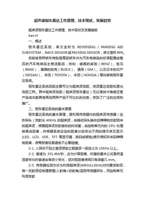
超声波倒车雷达工作原理、技术现状、发展趋势超声波倒车雷达工作原理、技术现状及发展趋势Ken.H一、概述倒车雷达系统,英文全称为REVERSING / PARKING AID SUBSYSTEM ,BACK SENSOR或PACKING SENSOR,英文简称RPA。
目前被各种轿车特别是高级轿车作为汽车电装品的标准配置或售后的汽车电装品主是选配品,例如:德国的奔驰(BENZ), 宝马(BMW),美国的别克(BUICK)、通用(GM)、以及日本的日产(NISSAN)、丰田(TOYOTA)、本田(HONDA)等均装有倒车雷达系统。
倒车雷达系统测距主要可分为超声波测距、微波雷达测距和激光测距三种。
其中超声波测距(超声波倒车雷达)无论是技术难度还是产品成本都具有其他两种产品不可比拟的优势,受到了广泛的应用和推广。
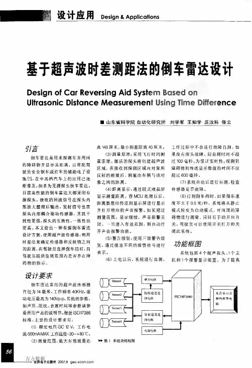
二、倒车雷达系统的基本原理倒车雷达系统的基本原理,是利用传感器内的超声波传感器(俗称探头)发射出40KHz的超声波,由接收探头接收经障碍物反射回来的超声波,根据超声波反射接收的时间差,由控制单元内的CPU处理换算成距离,并根据系统设定的距离分段发出不同的提示声及显示(LED、LCD、VDF、TFT等显示器,数码或颜色)提示得知车体到障碍物距离,使驾驶者轻易避免不必要碰撞。
2-1. 人耳听不到之音波频率之超音波一般定义为15KHz以上。
2-2. 音速为331.4M/秒,此为计算距离、时差的基本公式虽然温湿度变化时音速会有微小变化,但对短距离使用只有误差几mm。
2-3. 传感器检测方式为利用超声波(40KHz±2KHz)对对象发射后,有一反射波经物理原理(入射角=反射角)返回传感器探头,而控制单元利用发射3-1、在超声波传感器的种类可分为较传统的等方性传感器以及工艺水平更高的异方性传感器。
3-1-1、等方性传感器——→水平角度与垂直角度相同,例:120°:120°;3-1-2、异方性传感器——→水平角度与垂直角度不同,例:120°:60°或120°:45°3-2、传感器的侦测角度范围:3-2-1、在软件设计上:采用复杂的软件滤波方法,去除干扰信号,大幅度降低误判,与同类产品相比具有明显优势!3-2-2、在硬件设计上:将发射和接收电路设计在探头内部,使抗干扰性能有了根本突破!3-3、传感器的构造3-3-1、传感器的内部结构:一般而言,国内目前的倒车雷达传感器大多数使用的等方性传感器,其缺点在于垂直照射角度过大,容易探测到地,无法侦测较远的距离。
ANYANG INSTITUTE OF TECHNOLOGY本科毕业论文基于单片机的超声波测距倒车雷达设计The design of Ultrasonic ranging reverse radar based onSinglechip系(院)名称:专业班级:学生姓名:学生学号:指导教师姓名:指导教师职称:2011 年5 月毕业设计(论文)原创性声明和使用授权说明原创性声明本人郑重承诺:所呈交的毕业设计(论文),是我个人在指导教师的指导下进行的研究工作及取得的成果。
尽我所知,除文中特别加以标注和致谢的地方外,不包含其他人或组织已经发表或公布过的研究成果,也不包含我为获得安阳工学院及其它教育机构的学位或学历而使用过的材料。
对本研究提供过帮助和做出过贡献的个人或集体,均已在文中作了明确的说明并表示了谢意。
作者签名:日期:指导教师签名:日期:使用授权说明本人完全了解安阳工学院关于收集、保存、使用毕业设计(论文)的规定,即:按照学校要求提交毕业设计(论文)的印刷本和电子版本;学校有权保存毕业设计(论文)的印刷本和电子版,并提供目录检索与阅览服务;学校可以采用影印、缩印、数字化或其它复制手段保存论文;在不以赢利为目的前提下,学校可以公布论文的部分或全部内容。
作者签名:日期:目录摘要 (Ⅰ)Abstract (Ⅱ)引言 (1)第一章方案论证及选择 (2)1.1 微处理器选择 (2)1.2测距传感器选择 (2)1.3语音报警器的选择 (3)1.4显示子系统的设计 (3)第二章超声波测距雷达工作原理 (4)2.1超声波传感器介绍 (4)2.1.1超声波传感器的特性 (6)2.2 超声波测距的原理及实现 (7)第三章硬件设计 (8)3.1系统总体结构框图 (8)3.2 AT89C51单片机 (8)3.3 电源电路 (11)3.4 时钟电路 (12)3.5 复位电路 (12)3.6 超声波测距模块HC-SR04 (13)3.7 74HC573芯片 (15)3.8 数码管显示及报警电路设计 (16)第四章系统软件设计 (19)4.1系统主程序的设计 (19)4.2中断处理程序的设计 (21)4.3测距模块的设计 (22)4.4显示及报警模块的设计 (22)结论 (24)致谢 ............................................................................................ 错误!未定义书签。

图2超声波发射电路
波频率38kHz与测距的超声波频率40kHz较为接近,所
以可以利用它制作超声波检测接收电路。
CX20106接收超
声波具有很高的灵敏度和较强的抗干扰能力。
为了改变接
收电路的灵敏度和抗干扰能力,可以调整电容C,当无信
号时,输出高电平,当接收到回波信号后跳变为低电平。
图3超声波接受电路
2.3数码显示模块
超声波是机械波的一种是通过机械产生的声波,当他在空气中传播的时候,会受到空气温度和环境的影响,当
我们需要其进行精确测量的时候,就需要在系统中安装温
度模块来对当时的声波速度进行校正,来达到精确的目图1超声波测距报警系统原理图
图5超声波测距报警系统程序流程图
图4超声波报警电路
系统软件件设计
软件控制系统是系统的重要组成部分,本次雷达系
统选择运用C语言程序进行系统编写。
在本次设计的雷。
郑州轻院轻工职业学院专科毕业设计(论文)题目超声波倒车雷达系统硬件设计学生姓名专业班级学号院(系)机电工程系指导教师(职称)完成时间2017年 05月01 日超声波倒车雷达系统的设计摘要基于超声波测距的汽车倒车雷达系统是在充分理解了超声波测距原理的基础上提出的。
工作时,超声波传感器发出脉冲信号,经障碍物反射后由超声波接收装置接收并送至单片机处理,可实现倒车时障碍物距离的实时监测并通过语音报警提示驾驶员。
本设计是以AT89C51单片机为主控制器的超声波倒车雷达系统,包括超声波发射和接收部分、单片机处理部分、LCD显示部分和语音报警部分等硬件系统以及软件程序设计。
关键词倒车雷达/单片机控制/超声波测距Design of Ultrasonic Reversing Radar SystemAbstractBased on the ultrasonic distance measurement principle,this text put forward a design scheme of car reversing radar system based on ultrasonic distance measurement. Ultrasonic sensor sends a pulse signal when it is working,and the ultrasonic receiving decive send the reflected signal by the obstacle to the MCU,this system could achieve Real-time monitoring of the Obstacle distance when reversing and prompt the driver by voice alarm.The overall design of ultrasonic reversing radar system based on the AT89C51 single chip as main controller was detailed introduced,include Ultrasonic transmitting and receiving part,MCU processing part,display by LCD, V oice Alarm part and its programming in the software.Keywords Reversing radar,single chip microprocessor,ultrasonic distance measurement目录中文摘要英文摘要1 引言 (1)1.1 设计主要内容 (1)2 系统的总体设计方案及理论基础 (1)2.1 总体设计方案 (1)2.2 超声波测距理论分析 (2)2.2.1 超声波测距原理 (2)2.3 超声波传感器 (3)2.3.1 超声波传感器的原理及结构 (3)2.3.2 超声波传感器的应用 (4)2.2.3 超声波传感器的主要性能指标 (4)3 系统的硬件设计 (5)3.1 单片机主控系统电路设计 (5)3.1.1 单片机选择 (5)3.1.2 电源电路 (6)3.1.3 复位电路 (6)3.1.4 时钟电路 (7)3.2 超声波发射电路 (7)3.3 超声波检测接收电路 (9)3.3.1集成电路CX20106A (9)3.3.2 超声波接收电路 (10)3.4 数码管显示模块 (10)4 系统的软件设计 (11)4.1 软件设计的要求 (11)4.2 主程序设计 (12)4.3 超声波测距模块设计 (12)4.3.2 超声波发送和接收程序 (13)5主程序 (14)5.1 显示程序 (14)5.2 超声波测距程序 (14)实训主要元器件介绍 (17)6 系统的仿真调试 (25)6.1 系统仿真调试内容 (25)6.2 实验的误差分析 (26)结束语 (27)致谢 (28)参考文献 (29)附录 (30)原件清单 (31)1 引言倒车,是每位驾驶员都必须掌握的技能,如同前行一样需要小心谨慎,每年都有倒车引起事故的报道,轻则对自己的车和他人的财物造成损伤,重则可能危及人的性命,尤其是对儿童危害较大,他们体型较小,仅从后视镜来获取视野指导倒车仍有可能会对让们造成伤害。
外文翻译毕业设计题目:超声波倒车雷达预警原文1:DISTANCE MEASURING AND MONITORING DEVICE EQUIPPED AUTOMOBILE REVERSE RADAR译文1:距离测量和监控设备装备汽车反向雷达原文2:ULTRASONIC SENSOR ASSEMBLY FOR AVEHICLE REVERSING RADAR译文2DISTANCE MEASURING AND MONITORING DEVICE EQUIPPED AUTOMOBILE REVERSE RADAR(原文1)This design relates to an automobile commutating radar, an ultrasonic sensor comprising the radar. The ordinary car commutation radar is usually installed in the rear bumper of a car. The vehicle has a commutation radar sensor, a ceramic chip in the polarization electric field, due to the reverse piezoelectric vibration of the aluminum housing and transmitting an ultrasonic signal, and receiving the reflected ultrasonic signal into an effective distance. Therefore, a driver will know that this situation is reversed in the rear of the vehicle do not have to stop looking for the front of the vehicle.A good ultrasonic sensor ultrasonic signal should be sent to a central area, produced a strong reaction in order to achieve a sensitive detection. The distance along the line of its axis with reference to Figure 5, a conventional ultrasonic sensor sensitive areas, the reception sensitivity in a test has 250 cm, and a sensitive, including 60 degree angle in the above 2 (X) cm. Thus, the conventional sensor performance has a low accuracyIn some vehicles, the most traditional ultrasonic sensor mounted in the front and rear bumpers. Vehicles of a monitor in a dashboard display, ultrasonic sensor detects an obstacle. However, with the conventional ultrasonic sensor has a sensitive wide angle, they must be installed in the end of the bumper to prevent the ultrasonic signals interfere with each other. However, the distance in each ultrasonic sensor is so large is still very low detection accuracy.In addition, when parking the vehicle, ultrasonic sensors often detect other vehicles parked next to the vehicle as an obstacle, so the driver may be a false alarm.Accordingly, the present design provides an improved ultrasonic sensors to reduce or eliminate the above problems.Summary of the designThe main purpose is to provide the design of an ultrasonic sensor sensitive to the radar has high precision long distance and a little sensitive to the angle of the car for. Other objectives, advantages and novel features of the design will become more apparent from the following detailed description together when an ultrasonic transducer assembly of the vehicle the commutation radar has an ultrasonic sensor and the two wires. A sleeve is received by the rubbermaterial and has a chamber sensor. A tapered opening that is defined in a front chamber. A wave guide cone is provided to open and close to the sensor in the center of the tapered. By using the sensor assembly, automotive radar there is a reversal of precision long detection distance in a concentrated area.The reference to the diagram, an ultrasonic sensor assembly for a car reversing radar, in accordance with the design consists of a sensor, a set, a guided wave cone, and a housing (ultrasonic sensor has a structure like traditional sensors, and two wires extending from sensors.Sleeve, usually made of rubber, there is one which is defined as the receiving sensor. A tapered shape of the opening is defined at the front and an opening formed on the lower side to prevent the ultrasonic signal reflected from the ground to cause false alarms. A flange formed on the rear of the sleeve.The definition channel for receiving signals. A rear cover is provided on the rear side of the space to encapsulate the sensor and the sleeve inside.In the assembled state shown in Figure 2, the guide wave cone installed you like bracket combination conical opening of the center of the casing and highlights. The heating wire extends the bracket backward and exit back cover. The sleeve is placed in the housing flange butt shoulder wires and heating wire extends from the back cover of the diaphragm. A pad, made of a resin or other soft material, is provided between the sleeve is An ci back cover, so the sleeve and the sensor housing can be stably received.Figure 4 illustrates a detector effect Contrast sensor and unguided wave cone, wherein the solid line illustrates the sensor wave guide cone, and the conflict lines described sensor without the guided wave taper. As shown in Figure 4, at a test frequency of about 40 kHz (35 kHz), gift of design of the sensor can be provided to an ultrasonic signal with a Federation higher than traditional sensors. Therefore, the design of detection better than traditional sensors作者:Joan Smith;Mike Howard ;国籍:USA出处:United States Patent距离测量和监控设备装备汽车反向雷达(译文1)本设计涉及一种汽车换向雷达,用一个超声波传感器组成该雷达。
汽车倒车测距仪外文文献及翻译(文档含中英文对照即英文原文和中文翻译) 汽车倒车测距仪的设计摘要本文介绍了汽车倒车测距仪的功能确定、测距原理、设计方法及技术实现,介绍了汽车与障碍物间距离测量的信号处理方法。
论述了如何有效地测出并实时地显示出汽车与障碍物的距离,规定了各种不同的报警类型,对于相关类测量系统设计有一定的参考意义。
关键词超声单片机测距信号调理随着汽车产业的发展和人们生活水平的不断提高,汽车的数量逐年增加,例如1999 年,我国的汽车年产量已突破了180 万辆,造成公路、街道、停车场、车库等越来越拥挤不堪。
汽车驾驶员越来越为车的安全担心了,其中倒车就是一个典型,在繁忙、拥挤、狭窄的地方倒车时,驾驶员即得“瞻前”,又要“顾后”,往往一不小心,就会与汽车尾部障碍物发生碰撞事件。
经过调查,对绝大部分非职业汽车驾驶员都希望有一种能发现汽车尾部障碍物的“后视眼”———倒车测距仪,因此我们设计了一种经济实惠的汽车倒车测距仪,可以解决驾驶员的“后顾之忧”。
1 汽车倒车测距仪的功能指标确定经过对许多汽车驾驶员的调查,确定主要功能指标如下:(1) 最大测距5. 00 米,最小测距0. 35 米,实时数字显示测得距离,显示分辨率0. 01 米;(2) 超过5. 00 米为溢出,仅显示小数点,当距离小于0. 35 米时,显示为0. 00 ,表示很危险;(3) 灯光报警:当距离小于0. 60 米时,报警指示灯亮;(4) 声音报警:当距离小于1. 20 米时蜂鸣器发出间隔频率为1 Hz 的Bi ⋯Bi ⋯声,当距离小于0. 90米时蜂鸣器发出间隔频率为2 Hz 的Bi ⋯Bi ⋯声,当距离小于0. 60 米时蜂鸣器发出间隔频率为5 Hz 的Bi ⋯Bi ⋯声,当距离小于0. 35 米时蜂鸣器连续发出BiBiBi 声。
2 测距原理根据声音传播过程中遇到障碍物会发生反射这一原理可以测量距离,超声波测距也是这个原理,即用超声脉冲发射和接收其回波之间的时间差来计算距离,计算公式如下:V = 331. 5 + 0. 607 T式中:V ———超声波在空气中传播速度,其单位为米/ 秒,T ———环境温度,单位为℃。
目录第一章引言...................................................... 2第二章超声波倒车雷达简介 ....................................... 32.1 倒车雷达..................................................... 32.2 超声波....................................................... 32.3 超声波测距的原理............................................. 32.4 倒车雷达性能指标............................................. 4影响倒车雷达性能的因素 .......................................... 42.5.1 测量精度 ........................................... 42.5.2 探测范围 ........................................... 5第三章倒车雷达的电路结构 ....................................... 73.1 超声波发送模块............................................... 73.2 超声波接收模块............................................... 73.3 语音电路设计................................................. 8第四章倒车雷达的电路实现 ....................................... 9超声传感器的参数选择............................................. 94.2 总体结构..................................................... 94.3 基于单片机的硬件实现 ...................................... 104.3.1 超声波发射电路 ................................... 10超声波接收电路 ......................................... 124.3.3 温度测量电路 ..................................... 144.3.4 显示及报警电路 ................................... 154.4 超声波测距的倒车雷达软件设计 .............................. 16第五章倒车雷达超声测距的误差分析 ............................. 20第六章结论.................................................... 21致谢........................................................... 22参考文献....................................................... 23摘要:研究了基于单片机的超声测距倒车雷达。
2007级毕业(设计)论文信息工程学院系(院)电子信息工程专业中英文献翻译题目基于超声波检测的倒车雷达设计(硬件设计)学生姓名班级 2007电子信息工程学号指导教师日期2011年03 月 21 日教务处订制AT89C2051 Microcontroller Instructions1.1 Features∙Compatible with MCS-51 Products∙ 2 Kbytes of Reprogrammable Flash MemoryEndurance: 1,000 Write/Erase Cycles∙ 2.7 V to 6 V Operating Range∙Fully Static Operation: 0 Hz to 24 MHz∙Two-Level Program Memory Lock∙128 x 8-Bit Internal RAM∙15 Programmable I/O Lines∙Two 16-Bit Timer/Counters∙Six Interrupt Sources∙Programmable Serial UART Channel∙Direct LED Drive Outputs∙On-Chip Analog Comparator∙Low Power Idle and Power Down Modes1.2 DescriptionThe A T89C2051 is a low-voltage, high-performance CMOS 8-bit microcomputer with 2 Kbytes of Flash programmable and erasable read only memory (PEROM). The device is manufac tured using Atmel’s high density nonvolatile memory technology and is compatible with the industry standard MCS-51 instruction set and pinout. By combining a versatile 8-bit CPU with Flash on a monolithic chip, the Atmel A T89C2051 is a powerful microcomputer which provides a highly flexible and cost effective solution to many embedded control applications.The AT89C2051 provides the following standard features: 2 Kbytes of Flash, 128 bytes of RAM, 15 I/O lines, two 16-bit timer/counters, a five vector two-level interrupt architecture, a full duplex serial port, a precision analog comparator, on-chip oscillator and clock circuitry. In addition, the AT89C2051 is designed with static logic for operation down to zero frequency and supports two software selectable power saving modes. TheIdle Mode stops the CPU while allowing the RAM, timer/counters, serial port and interrupt system to continue functioning. The Power Down Mode saves the RAM contents but freezes the oscillator disabling all other chip functions until the next hardware reset.1.3 Pin Configuration1.4 Pin DescriptionVCC Supply voltage.GND Ground.Port 1Port 1 is an 8-bit bidirectional I/O port. Port pins P1.2 to P1.7 provide internal pullups. P1.0 and P1.1 require external pullups. P1.0 and P1.1 also serve as the positive input (AIN0) and the negative input (AIN1), respectively, of the on-chip precision analog comparator. The Port 1 output buffers can sink 20 mA and can drive LED displays directly. When 1s are written to Port 1 pins, they can be used as inputs. When pins P1.2 to P1.7 are used as inputs and are externally pulled low, they will source current (IIL) because of the internal pullups.Port 1 also receives code data during Flash programming and program verification.Port 3Port 3 pins P3.0 to P3.5, P3.7 are seven bidirectional I/O pins with internal pullups. P3.6 is hard-wired as an input to the output of the on-chip comparator and is not accessible as a general purpose I/O pin. The Port 3 output buffers can sink 20 mA. When 1s are written to Port 3 pins they are pulled high by the internal pullups and can be used as inputs. As inputs, Port 3 pins thatare externally being pulled low will source current (IIL) because of the pullups.Port Alternate FunctionsP3.0 RXD (serial input port)P3.1 TXD (serial output port)P3.2 INT0 (external interrupt 0)P3.3 INT1 (external interrupt 1)P3.4 T0 (timer 0 external input)P3.5 T1 (timer 1 external input)Port 3 also serves the functions of various special features of the A T89C2051 as listed below:1.5 Oscillator CharacteristicsXTAL1 and XTAL2 are the input and output, respectively, of an inverting amplifier which can be configured for use as an on-chip oscillator, as shown in Figure 1. Either a quartz crystal or ceramic resonator may be used. To drive the device from an external clock source, XTAL2 should be left unconnected while XTAL1 is driven as shown in Figure 2. There are no re-quirements on the duty cycle of the external clock signal, since the input to the internal clocking circuitry is through a divideby-two flip-flop, but minimum and maximum voltage high and low time specifications must be observed.1.6 Special Function RegistersA map of the on-chip memory area called the Special Function Register (SFR) space is shown in the table below.Note that not all of the addresses are occupied, and unoccupied addresses may not be implemented on the chip. Read accesses. to these addresses will in general return random data, and write accesses will have an indeterminate effect.User software should not write 1s to these unlisted locations, since they may be used in future products to invoke new fea tures. In that case, the reset or inactive values of the new bits will always be 0.1.7 Restrictions on Certain InstructionsThe AT89C2051 and is an economical and cost-effective mem ber of Atmel’s growingfamily of microcontrollers. It contains 2 Kbytes of flash program memory. It is fully compatible with the MCS-51 architecture, and can be programmed using the MCS-51 instruction set. However, there are a few considerations one must keep in mind when utilizing certain instructions to program this device.All the instructions related to jumping or branching should be restricted such that the destination address falls within the physical program memory space of the device, which is 2K for the AT89C2051. This should be the responsibility of the software programmer. For example, LJMP 7E0H would be a valid instruction for the AT89C2051 (with 2K of memory), whereas LJMP 900H would not.1. Branching instructions:LCALL, LJMP, ACALL, AJMP, SJMP, JMP @A+DPTRThese unconditional branching instructions will execute correctly as long as the programmer keeps in mind that the destination branching address must fall within the physical boundaries of the program memory size (locations 00H to 7FFH for the 89C2051). Violating the physical space limits may cause unknown program behavior.CJNE [...], DJNZ [...], JB, JNB, JC, JNC, JBC, JZ, JNZ With these conditional branching instructions the same rule above applies. Again, violating the memory boundaries may cause erratic execution.For applications involving interrupts the normal interrupt service routine address locations of the 80C51 family architecture have been preserved.2. MOVX-related instructions, Data Memory:The A T89C2051 contains 128 bytes of internal data memory. Thus, in the A T89C2051 the stack depth is limited to 128 bytes, the amount of available RAM. External DA TA memory access is not supported in this device, nor is external PROGRAM memory execution. Therefore, no MOVX [...] instructions should be included in the program.A typical 80C51 assembler will still assemble instructions, even if they are written in violation of the restrictions mentioned above. It is the responsibility of the controller user to know the physical features and limitations of the device being used and adjust the instructions used correspondingly.1.8 Program Memory Lock BitsOn the chip are two lock bits which can be left unprogrammed (U) or can be programmed (P) to obtain the additional features listed in the table below:Lock Bit Protection Modes(1)Program Lock BitsLB1 LB2 Protection Type1 U U No program lock features.2 P U Further programming of the Flash is disabled.3 P P Same as mode 2, also verify is disabled.Note: 1. The Lock Bits can only be erased with the Chip Erase operation1.9 Idle ModeIn idle mode, the CPU puts itself to sleep while all the on-chip peripherals remain active. The mode is invoked by software. The content of the on-chip RAM and all the special functions registers remain unchanged during this mode. The idle mode can be terminated by any enabled interrupt or by a hardware reset.P1.0 and P1.1 should be set to ’0’ if no external pullups are used, or set to ’1’ if external pullups are used.It should be noted that when idle is terminated by a hardware reset, the device normally resumes program execution, from where it left off, up to two machine cycles before the internal reset algorithm takes control. On-chip hardware inhibits access to internal RAM in this event, but access to the port pins is not inhibited. To eliminate the possibility of an unexpected write to a port pin when Idle is terminated by reset, the instruction following the one that invokes Idle should not be one that writes to a port pin or to external memory.1.10 Power Down ModeIn the power down mode the oscillator is stopped, and the instruction that invokes power down is the last instruction executed. The on-chip RAM and Special Function Registers retain their values until the power down mode is terminated. The only exit from power down is ahardware reset. Reset redefines the SFRs but does not change the on-chip RAM. The reset should not be activated before VCC is restored to its normal operating level and must be held active long enough to allow the oscillator to restart and stabilize.P1.0 and P1.1 should be set to ’0’ if no external pullups are used, or set to ’1’ if external pullups are used.1.11 Programming The FlashThe A T89C2051 is shipped with the 2 Kbytes of on-chip PEROM code memory array in the erased state (i.e., contents = FFH) and ready to be programmed. The code memory array is programmed one byte at a time. Once the array is programmed, to re-program any non-blank byte, the entire memory array needs to be erased electrically.Internal Address Counter: The A T89C2051 contains an internal PEROM address counter which is always reset to 000H on the rising edge of RST and is advanced by applying a positive going pulse to pin XTAL1.Programming Algorithm: To program the A T89C2051, the following sequence is recommended.1. Power-up sequence:Apply power between VCC and GND pins Set RST and XTAL1 to GNDWith all other pins floating, wait for greater than 10 milliseconds2. Set pin RST to ’H’ Set pin P3.2 to ’H’3. Apply the appropriate combination of ’H’ or ’L’ logic levels to pins P3.3, P3.4, P3.5, P3.7 to select one of the programming operations shown in the PEROM Programming Modes table.To Program and V erify the Array:4. Apply data for Code byte at location 000H to P1.0 to P1.7.5. Raise RST to 12V to enable programming.6. Pulse P3.2 once to program a byte in the PEROM array or the lock bits. The byte-write cycle is self-timed and typically takes 1.2 ms.7. To verify the programmed data, lower RST from 12V to logic ’H’ level and set pins P3.3 to P3.7 to the appropiate levels. Output data can be read at the port P1 pins.8. To program a byte at the next address location, pulse XTAL1 pin once to advance theinternal address counter. Apply new data to the port P1 pins.9. Repeat steps 5 through 8, changing data and advancing the address counter for the entire 2 Kbytes array or until the end of the object file is reached.10. Power-off sequence: se t XTAL1 to ’L’ set RST to ’L’Float all other I/O pins Turn Vcc power offData Polling: The AT89C2051 features Data Polling to indicate the end of a write cycle. During a write cycle, an attempted read of the last byte written will result in the complement of the written data on P1.7. Once the write cycle has been completed, true data is valid on all outputs, and the next cycle may begin. Data Polling may begin any time after a write cycle has been initiated.Ready/Busy: The Progress of byte programming can also be monitored by the RDY/BSY output signal. Pin P3.1 is pulled low after P3.2 goes High during programming to indicate BUSY. P3.1 is pulled High again when programming is done to indicate READY.Program Verify: If lock bits LB1 and LB2 have not been programmed code data can be read back via the data lines for verification:1. Reset the internal address counter to 000H by bringing RST from ’L’ to ’H’.2. Apply the appropriate control signals for Read Code data and read the output data at the port P1 pins.3. Pulse pin XTAL1 once to advance the internal address counter.4. Read the next code data byte at the port P1 pins.5. Repeat steps 3 and 4 until the entire array is read.The lock bits cannot be verified directly. V erification of the lock bits is achieved by observing that their features are enabled.Chip Erase: The entire PEROM array (2 Kbytes) and the two Lock Bits are erased electrically by using the proper combination of control signals and by holding P3.2 low for 10 ms. The code array is written with all "1"s in the Chip Erase operation and must be executed before any non-blank memory byte can be re-programmed.Reading the Signature Bytes: The signature bytes are read by the same procedure as a normal verification of locations 000H, 001H, and 002H, except that P3.5 and P3.7 must be pulled to a logic low. The values returned are as follows.(000H) = 1EH indicates manufactured by Atmel (001H) = 21H indicates 89C2051Programming InterfaceEvery code byte in the Flash array can be written and the entire array can be erased by using the appropriate combination of control signals. The write operation cycle is self-timed and once initiated, will automatically time itself to completion.All major programming vendors offer worldwide support for the Atmel microcontroller series. Please contact your local programming vendor for the appropriate software revision.Ultrasonic ranging system designPublication title: Sensor Review. Bradford: 1993. Vol.ABSTRACT:Ultrasonic ranging technology has wide using worth in many fields,such as the industrial locale,vehicle navigation and sonar engineering.Now it has been used in level measurement,self-guided autonomous vehicles, fieldwork robots automotive navigation,air and underwater target detection,identification,location and so on.So there is an important practicing meaning to learn the ranging theory and ways deeply. To improve the precision of the ultrasonic ranging system in hand,satisfy the request of the engineering personnel for the ranging precision,the bound and the usage,a portable ultrasonic ranging system based on the single chip processor was developed.Keywords:Ultrasound r,Ranging System,Single Chip Processor1.IntroductiveWith the development of science and technology, the improvement of people's standard of living, speeding up the development and construction of the city. urban drainage system have greatly developed their situation is constantly improving. However, due to historical reasons many unpredictable factors in the synthesis of her time, the city drainage system. In particular drainage system often lags behind urban construction. Therefore, there are often good building excavation has been building facilities to upgrade the drainage system phenomenon. It brought to the city sewage, and it is clear to the city sewage and drainage culvert in the sewage treatment system. comfort is very important to people's lives. Mobile robots designed to clear the drainage culvert and the automatic control system Free sewage culvert clear guarantee robot, the robot is designed to clear the culvert sewage to the core. Control System is the core component of the development of ultrasonic range finder. Therefore, it is very important to design a good ultrasonic range finder.2. A principle of ultrasonic distance measurement2.1 The principle of piezoelectric ultrasonic generatorPiezoelectric ultrasonic generator is the use of piezoelectric crystal resonators to work. Ultrasonic generator, the internal structure as shown, it has two piezoelectric chip and a resonance plate. When it's two plus pulse signal, the frequency equal to the intrinsic piezoelectric oscillation frequency chip, the chip will happen piezoelectric resonance, and promote the development of plate vibration resonance, ultrasound is generated. Conversely, if the two are not inter-electrode voltage, when the board received ultrasonic resonance, it will be for vibration suppression of piezoelectric chip, the mechanical energy is converted to electrical signals, then it becomes the ultrasonic receiver.The traditional way to determine the moment of the echo's arrival is based on thresholding the received signal with a fixed reference. The threshold is chosen well above the noise level, whereas the moment of arrival of an echo is defined as the first moment the echo signal surpasses that threshold. The intensity of an echo reflecting from an object strongly depends on the object's nature, size and distance from the sensor. Further, the time interval from the echo's starting point to the moment when it surpasses the threshold changes with the intensity of the echo. As a consequence, a considerable error may occur Even two echoes with different intensities arriving exactly at the same time will surpass the threshold at different moments. The stronger one will surpass the threshold earlier than the weaker, so it will be considered as belonging to a nearer object.2.2The principle of ultrasonic distance measurementUltrasonic transmitter in a direction to launch ultrasound, in the moment to launch the beginning of time at the same time, the spread of ultrasound in the air, obstacles on his way to return immediately, the ultrasonic reflected wave received by the receiver immediately stop the clock. Ultrasound in the air as the propagation velocity of 340m / s, according to the timer records the time t, we can calculate the distance between the launch distance barrier (s), that is: s = 340t / 23.Ultrasonic Ranging System for the Second Circuit DesignSystem is characterized by single-chip microcomputer to control the use of ultrasonic transmitter and ultrasonic receiver since the launch from time to time, single-chip selection of 8751, economic-to-use, and the chip has 4K of ROM, to facilitate programming. Circuit schematic diagram shown in Figure 2.Figure 1 circuit principle diagram3.1 40 kHz ultrasonic pulse generated with the launchRanging system using the ultrasonic sensor of piezoelectric ceramic sensors UCM40, its operating voltage of the pulse signal is 40kHz, which by the single-chip implementation of the following procedures to generate.puzel: mov 14h, # 12h; ultrasonic firing continued 200mshere: cpl p1.0; output 40kHz square waveRanging in front of single-chip termination circuit P1.0 input port, single chip implementation of the above procedure, the P1.0 port in a 40kHz pulse output signal, after amplification transistor T, the drive to launch the first ultrasonic UCM40T, issued 40kHz ultrasonic pulse, and the continued launch of 200ms. Ranging the right and the left side of the circuit, respectively, then input port P1.1 and P1.2, the working principle and circuit in front of the same location.3.2 Reception and processing of ultrasonicUsed to receive the first launch of the first pair UCM40R, the ultrasonic pulse modulation signal into an alternating voltage, the op-amp amplification IC1A and after polarization IC1B to IC2. IC2 is locked loop with audio decoder chip LM567, internal voltage-controlled oscillator center frequency of f0 = 1/1.1R8C3, capacitor C4 determine their target bandwidth. R8-conditioning in the launch of the carrier frequency on the LM567 input signal is greater than 25mV, the output from the high jump 8 feet into a low-level, as interrupt request signals to the single-chip processing.Ranging in front of single-chip termination circuit output port INT0 interrupt the highest priority, right or left location of the output circuit with output gate IC3A access INT1 port single-chip, while single-chip P1.3 and P1. 4 received input IC3A, interrupted by the process to identify the source of inquiry to deal with, interrupt priority level for the first left right after. Part of the source code is as follows:receive1: push pswpush accclr ex1; related external interrupt 1jnb p1.1, right; P1.1 pin to 0, ranging from right to interrupt service routine circuitjnb p1.2, left; P1.2 pin to 0, to the left ranging circuit interrupt service routinereturn: SETB EX1; open external interrupt 1pop accpop pswretiright: ...; right location entrance circuit interrupt service routineAjmp Returnleft: ...; left Ranging entrance circuit interrupt service routineAjmp Return3.3 The calculation of ultrasonic propagation timeWhen you start firing at the same time start the single-chip circuitry within the timer T0, the use of timer counting function records the time and the launch of ultrasonic reflected wave received time. When you receive the ultrasonic reflected wave, the receiver circuit outputs a negative jump in the end of INT0 or INT1 interrupt request generates a signal, single-chip microcomputer in response to external interrupt request, the implementation of the external interrupt service subroutine, read the time difference, calculating the distance . Some of its source code is as follows:RECEIVE0: PUSH PSWPUSH ACCCLR EX0; related external interrupt 0MOV R7, TH0; read the time valueMOV R6, TL0CLR CMOV A, R6SUBB A, # 0BBH; calculate the time differenceMOV 31H, A; storage resultsMOV A, R7SUBB A, # 3CHMOV 30H, ASETB EX0; open external interrupt 0POP ACCPOP PSWRETIFor a flat target, a distance measurement consists of two phases: a coarse measurement and. a fine measurement:Step 1: Transmission of one pulse train to produce a simple ultrasonic wave.Step 2: Changing the gain of both echo amplifiers according to equation , until the echo is detected.Step 3: Detection of the amplitudes and zero-crossing times of both echoes.Step 4: Setting the gains of both echo amplifiers to normalize the output at, say 3 volts. Setting the period of the next pulses according to the : period of echoes. Setting the time window according to the data of step 2.Step 5: Sending two pulse trains to produce an interfered wave. Testing the zero-crossing times and amplitudes of the echoes. If phase inversion occurs in the echo, determine to otherwise calculate to by interpolation using the amplitudes near the trough. Derive t sub m1 and t sub m2 .Step 6: Calculation of the distance y using equation .4. The ultrasonic ranging system software designSoftware is divided into two parts, the main program and interrupt service routine. Completion of the work of the main program is initialized, each sequence of ultrasonic transmitting and receiving control.Interrupt service routines from time to time to complete three of the rotation direction of ultrasonic launch, the main external interrupt service subroutine to read the value of completion time, distance calculation, the results of the output and so on.5. ConclusionsRequired measuring range of 30cm ~ 200cm objects inside the plane to do a number of measurements found that the maximum error is 0.5cm, and good reproducibility.Single-chip design can be seen on the ultrasonic ranging system has a hardware structure is simple, reliable, small features such as measurement error. Therefore, it can be used not only for mobile robot can be used in other detection systems.Thoughts: As for why the receiver do not have the transistor amplifier circuit, because the magnification well, integrated amplifier, but also with automatic gain control level, magnification to 76dB, the center frequency is 38k to 40k, is exactly resonant ultrasonic sensors frequency.AT89C2051微控制器的指令一、特点•兼容MCS - 51产品•2个字节的可再编程闪存耐力擦写/擦除周期•2. 7 V至6 V工作范围•全静态操作0 Hz至24 MHz的•两级程序存储器锁定•128 ×8位内部RAM•15个可编程I / O线•2个16位定时器/计数器•六个中断源•可编程串行UART通道•直接LED驱动输出•片上模拟比较器•低功耗空闲和掉电模式二、说明该AT89C2051是一个低电压,高性能CMOS 8位2 Kby ¬的Flash可编程,可擦除只读存储器(PEROM)设备是制造¬ tured采用Atmel的高密度非易失性内存技术,并与兼容的工商业污水附加费微机工业标准MCS - 51指令集,并通过结合在一个通用的单芯片闪存的8位CPU引脚,Atmel的AT89C2051是一种功能强大的微机提供了高度灵活和成本效益的解决方案,许多嵌入式控制应用该AT89C2051提供以下标准功能2字节的闪存,128字节RAM,15 I / O线,两个16位定时器/计数器,一个五向量2级中断结构,一个全双工串行口,一个精密模拟比较器,片上振荡器和时钟电路此外,该AT89C2051的设计与操作频率下降到零静态逻辑,支持两种软件可选的节电模式空闲模式时CPU停止工作,同时允许RAM,定时/计数器,串行口和中断系统继续工作暂停模式保存RAM的内容,但冻结,直到下一个硬件复位振荡器禁用所有其他芯片功能三、引脚配置四、引脚说明VCC电源电压GND接地端口1端口1是一个8位双向I / O端口端口引脚P1 2至7提供P1 P1和P1 0 1 0内部上拉需要P1和P1 1外部上拉也可作为正输入(AIN0)和负输入(AIN1 ),分别对片内精密模拟比较器的端口1输出缓冲器可以吸收20mA的电流,并且可以直接驱动LED时1秒写入端口1引脚,它们可以作为输入引脚P1 2时至P17顷作为输入,并从外部拉低,将输出电流(IIL)由于内部上拉在端口1也接收片内Flash存储。
基于超声波测距的倒车报警系统设计一、本文概述Overview of this article随着汽车工业的快速发展和智能化技术的进步,车辆安全性能越来越受到人们的关注。
倒车安全作为其中的重要环节,直接关系到驾驶员和行人的安全。
因此,设计一种高效、可靠的倒车报警系统显得尤为重要。
本文旨在探讨基于超声波测距技术的倒车报警系统设计。
With the rapid development of the automotive industry and the advancement of intelligent technology, vehicle safety performance is receiving increasing attention from people. Reverse safety, as an important aspect, directly affects the safety of drivers and pedestrians. Therefore, designing an efficient and reliable reverse alarm system is particularly important. This article aims to explore the design of a reverse alarm system based on ultrasonic ranging technology.超声波测距技术以其非接触、高精度、响应速度快等优点,在倒车报警系统中具有广泛的应用前景。
通过发射超声波并接收其回波,可以精确测量车辆与障碍物之间的距离,从而及时提醒驾驶员,避免发生碰撞事故。
Ultrasonic ranging technology has broad application prospects in reverse alarm systems due to its non-contact, high precision, and fast response speed advantages. By emitting ultrasonic waves and receiving their echoes, the distance between the vehicle and obstacles can be accurately measured, thereby timely alerting the driver and avoiding collision accidents.本文将详细介绍基于超声波测距的倒车报警系统的设计原理、硬件组成、软件编程以及实际应用效果。
KC021-1 毕业设计说明书题目:基于CPLD的超声波倒车雷达设计实现二级学院(直属学部):专业:班级:0学生姓名:学号:指导教师姓名:职称:评阅教师姓名:职称:2012 年06 月摘要倒车雷达全称叫倒车防撞雷达,也叫泊车辅助装置,是汽车泊车或者倒车时的安全辅助装置。
能以声音或者更为直观的显示告知驾驶员周围障碍物的情况,解除了驾驶员泊车、倒车和起动车辆时前后左右探视所引起的困扰,并帮助驾驶员扫除了视野死角和视线模糊的缺陷,提高驾驶的安全性。
本文主要介绍了基于CPLD的超声波倒车雷达的设计,仿真和调试。
本文所设计的倒车雷达可分为两部分:1.超声波测距部分:用超声波传感器做探头,用CPLD控制,获得障碍物的距离将数据输入控制芯片。
2.CPLD控制部分:CPLD控制芯片要实现分频器,计数器,乘法器,译码器等功能。
本文所采用的是ALTERA公司推出的MAXII系列芯片的ZRtech COREC-240U开发套件。
使用QuartusII 进行软件的设计,所有的程序采用VHDL硬件描述语言,经过仿真后下载到开发板上验证,调试到整个系统正常工作。
关键词:倒车雷达; CPLD;超声波测距;QuartusIIIAbstractThe backing car radar full name is backing car anti-collision radar also known as the parking assistant system, it is a safe auxiliary device when parking or reversing the car. It could make the driver known barriers around through the sound or a more intuitive display. It can solve the trouble of visit when the driver parking, reversing or starting the car. It can remove the vision dead ends and blurred vision to improve driving safe.This paper mainly introduces the design, simulation and test of backing car radar based on CPLD. The backing car radar in this paper can divided into two parts:1. the part of ultrasonic distance measurement: using the ultrasonic sensors as probe, using CPLD to control, when get the data from obstacles, put the data to the control chip. 2.CPLD control part: CPLD control chip should realize dividers, counters, multipliers and decoder functions.This paper using the developing package of ZRtech COREC-240U .It from the series of chip MAXII made by ALTERA. This paper using the QuartusII software to designing and using the VHDL hardware language to writing all the programs. Through simulations and tests until all the systems can work well.Keywords: backing car radar;CPLD; ultrasonic ranging;QuartusIIII目录摘要 (I)ABSTRACT (II)目录 (III)第1章倒车雷达简介 (1)1.1课题的来源 (1)1.2倒车雷达原理 (1)1.3倒车雷达的发展 (1)1.3.1倒车雷达发展史 (1)1.3.2 倒车雷达发展趋势 (3)1.4倒车雷达市场需求 (3)1.5本章小结 (3)第2章 CPLD的介绍 (4)2.1可编程逻辑器件 (4)2.1.1 可编程逻辑器件的概述 (4)2.1.2 可编程逻辑器件的分类 (4)2.1.3 可编程逻辑器件的发展历程 (4)2.2CPLD与FPGA的比较 (5)2.2.1 CPLD与FPGA的特点 (5)2.2.2 CPLD与FPGA的区别 (6)2.3开发板的介绍 (6)2.4本章小结 (9)第3章系统的硬件设计 (10)3.1硬件的总体设计 (10)3.2MAXII系列芯片EPM240T100C5 (11)3.2.1 芯片EPM240T100C5的管脚图 (11)3.2.2 芯片EPM240T100C5的优点 (11)3.3超声波的发送和接收部分 (12)3.3.1 超声波测距原理 (12)3.3.2 超声波传感器 (13)3.3.3 超声波发射和接收电路 (15)III3.3.4 实验过程中发射和接收到的波形 (16)3.4报警模块 (17)3.5显示模块 (18)3.6电源模块 (20)3.7本章小结 (21)第4章系统的软件部分 (22)4.1CPLD的设计流程 (22)4.2系统程序流程图 (24)4.3软件编译的各个模块 (25)4.3.1 分频器模块 (25)4.3.2 显示模块 (27)4.3.3 乘法器模块 (28)4.3.4 计数器模块 (31)4.3.5 报警模块 (34)4.4本章小结 (34)第5章调试部分 (35)5.1软件部分的整合 (35)5.2软硬件的联合调试 (36)5.3本章小结 (37)结论 (38)致谢 (39)参考文献 (40)附录 A (42)附录 B (52)附录C (55)IV第1章倒车雷达简介倒车雷达全称叫“倒车防撞雷达”也叫“泊车辅助装置”是汽车泊车或者倒车时的安全辅助装置,由超声波传感器(俗称探头),控制器和显示器或蜂鸣器等部分组成。
基于超声波检测的倒车雷达的设计院系自动化学院专业测控技术与仪器班级5407102学号200504071055姓名吕坤指导教师刘利秋负责教师刘利秋沈阳航空工业学院2009年6月摘要本论文阐述的是基于超声波检测的倒车雷达的设计。
本课题利用超声波检测、单片机系统设计出一种汽车倒车雷达,并能将汽车与障碍物的距离用LED实时显示,同时对特定的距离进行声光报警。
本系统由两部分组成,硬件系统和软件系统。
硬件系统利用超声波发生电路驱动超声波发射探头发射超声波信号,再由超声波接收探头接收经障碍物反射回的超声波信号,并通过接收电路对信号进行调理,再将调理后的信号传入单片机系统,然后单片机系统将信号经过处理送显示,并且在规定的距离进行声光报警。
软件系统用汇编语言进行编程,采用模块化设计思想。
该系统通过联调后,实现了预期各种功能,符合设计要求。
关键词:倒车雷达;超声波传感器;单片机;LED显示AbstractThis paper introduces the design of car reversing radar based on the ultrasonic testing . The task uses ultrasonic testing and Single Chip Micyoco(SCM) syetem to design a kind of car reversing radar.The distance between car and barrier can be displayed on LED real time,and at the same time,the sound ang light alarmingcan be given at appointed distance. The syetem consist of two parts: hardware system and software system. In the hardware system,ultrasonic sound generating circuit drives emitting probe to send out ultrasonic signal and the receiving probe receives ultrasonic signal that is reflected from barrier.The received electrical signl is conditioned by the receiving circuit and put into SCM system after conditioning,where the signal is processed,then displayed,and the sound and light alarming will be given at the appointed distance. Assemble language is used in the software system and modularization design idea is adopted.This system realizes all desired functions and coincides with demand after system debugging. Keywords: Reversing radar; Ultrasonic sensor; Single Chip Micyoco ; LED display目录第1章绪论 (1)1.1课题产生的背景 (1)1.2本课题的主要任务及内容 (1)1.3本课题的任务分析与实现 (2)1.4本论文的主要内容安排 (3)第2章超声波测距的基本原理 (4)2.1超声波简介 (4)2.2 超声波测距原理 (4)第3章倒车雷达的硬件系统设计 (6)3.1超声波发射电路设计 (6)3.2超声波接收电路设计 (7)3.3单片机系统电路 (9)3.3.1单片机的选择 (9)3.3.2单片机外围电路的设计 (11)3.3.3显示电路的设计 (13)3.3.4 报警电路的设计 (14)第4章倒车雷达的软件系统设计 (15)4.1倒车雷达的软件设计方案 (15)4.2主程序设计 (16)4.3时差测量子程序 (17)4.4显示子程序 (17)4.5报警子程序 (18)第5章系统调试与分析 (20)5.1调试分析的一般过程 (20)5.2硬件调试 (20)5.3软件调试 (21)5.4汽车倒车雷达的系统调试 (21)5.5调试故障及原因分析 (22)5.6测试结果分析 (22)结论 (24)社会经济效益分析 (25)参考文献 (26)致谢 (27)附录Ⅰ汽车倒车雷达硬件系统原理图 (28)附录Ⅱ汽车倒车雷达软件程序清单 (29)附录Ⅲ汽车倒车雷达元器件清单 (43)第1章绪论1.1课题产生的背景随着经济的发展与汽车科学技术的进步,公路交通呈现出行驶高速化、车流密集化和驾驶员非职业化的趋势。
超声测距系统设计原文出处:传感器文摘布拉福德:1993年超声测距技术在工业现场、车辆导航、水声工程等领域都具有广泛的应用价值,目前已应用于物位测量、机器人自动导航以及空气中与水下的目标探测、识别、定位等场合。
因此,深入研究超声的测距理论和方法具有重要的实践意义。
为了进一步提高测距的精确度,满足工程人员对测量精度、测距量程和测距仪使用的要求,本文研制了一套基于单片机的便携式超声测距系统。
关键词:超声波,测距仪,单片机一、前言随着科技的发展,人们生活水平的提高,城市发展建设加快,城市给排水系统也有较大发展,其状况不断改善。
但是,由于历史原因合成时间住的许多不可预见因素,城市给排水系统,特别是排水系统往往落后于城市建设。
因此,经常出现开挖已经建设好的建筑设施来改造排水系统的现象。
城市污水给人们带来了困扰,因此箱涵的排污疏通对大城市给排水系统污水处理,人们生活舒适显得非常重要。
而设计研制箱涵排水疏通移动机器人的自动控制系统,保证机器人在箱涵中自由排污疏通,是箱涵排污疏通机器人的设计研制的核心部分。
控制系统核心部分就是超声波测距仪的研制。
因此,设计好的超声波测距仪就显得非常重要了。
二、超声波测距原理2.1压电式超声波发生器原理压电式超声波发生器实际上是利用压电晶体的谐振来工作的。
超声波发生器内部结构,它有两个压电晶片和一个共振板。
当它的两极外加脉冲信号,其频率等于压电晶片的固有振荡频率时,压电晶片将会发生共振,并带动共振板振动,便产生超声波。
反之,如果两电极间未外加电压,当共振板接收到超声波时,将压迫压电晶片作振动,将机械能转换为电信号,这时它就成为超声波接收器了。
测量脉冲到达时间的传统方法是以拥有固定参数的接收信号开端为基础的。
这个界限恰恰选于噪音水平之上,然而脉冲到达时间被定义为脉冲信号刚好超过界限的第一时刻。
一个物体的脉冲强度很大程度上取决于这个物体的自然属性尺寸还有它与传感器的距离。
进一步说,从脉冲起始点到刚好超过界限之间的时间段随着脉冲的强度而改变。
基于超声波检测的倒车雷达设计
滕志军
【期刊名称】《今日电子》
【年(卷),期】2006(000)009
【摘要】倒车雷达(Car Reversing Aid Systems)的全称是“倒车防撞雷达”,也称“泊车辅助装置”,是汽车泊车安全辅助装置,能以声音或者更为直观的显示告知驾驶员周围障碍物的情况,解除了驾驶员泊车和起动车辆时前后左右探视所引起的困扰,并帮助驾驶员扫除了视野死角和视线模糊的缺陷,提高了安全性。
【总页数】3页(P78-79,83)
【作者】滕志军
【作者单位】东北电力大学信息工程学院
【正文语种】中文
【中图分类】TN95
【相关文献】
1.超声波传感器检测的倒车雷达系统设计 [J], 乔振民
2.基于FPGA的超声波测距倒车雷达防撞系统设计 [J], 李营;夏景云;吕兆承;陈帅
3.基于MSP430单片机的超声波倒车雷达系统设计 [J], 陈希湘;朱嵘涛;王锦莉
4.基于MSP430的倒车雷达超声波测距系统设计 [J], 张皎;姚亦桐;杨小平;张博奥
5.基于超声波测距的倒车雷达系统设计 [J], 姜维福;王素青
因版权原因,仅展示原文概要,查看原文内容请购买。
外文翻译毕业设计题目:超声波倒车雷达预警原文1:DISTANCE MEASURING AND MONITORING DEVICE EQUIPPED AUTOMOBILE REVERSE RADAR译文1:距离测量和监控设备装备汽车反向雷达原文2:ULTRASONIC SENSOR ASSEMBLY FOR AVEHICLE REVERSING RADAR译文2DISTANCE MEASURING AND MONITORING DEVICE EQUIPPED AUTOMOBILE REVERSE RADAR(原文1)This design relates to an automobile commutating radar, an ultrasonic sensor comprising the radar. The ordinary car commutation radar is usually installed in the rear bumper of a car. The vehicle has a commutation radar sensor, a ceramic chip in the polarization electric field, due to the reverse piezoelectric vibration of the aluminum housing and transmitting an ultrasonic signal, and receiving the reflected ultrasonic signal into an effective distance. Therefore, a driver will know that this situation is reversed in the rear of the vehicle do not have to stop looking for the front of the vehicle.A good ultrasonic sensor ultrasonic signal should be sent to a central area, produced a strong reaction in order to achieve a sensitive detection. The distance along the line of its axis with reference to Figure 5, a conventional ultrasonic sensor sensitive areas, the reception sensitivity in a test has 250 cm, and a sensitive, including 60 degree angle in the above 2 (X) cm. Thus, the conventional sensor performance has a low accuracyIn some vehicles, the most traditional ultrasonic sensor mounted in the front and rear bumpers. Vehicles of a monitor in a dashboard display, ultrasonic sensor detects an obstacle. However, with the conventional ultrasonic sensor has a sensitive wide angle, they must be installed in the end of the bumper to prevent the ultrasonic signals interfere with each other. However, the distance in each ultrasonic sensor is so large is still very low detection accuracy.In addition, when parking the vehicle, ultrasonic sensors often detect other vehicles parked next to the vehicle as an obstacle, so the driver may be a false alarm.Accordingly, the present design provides an improved ultrasonic sensors to reduce or eliminate the above problems.Summary of the designThe main purpose is to provide the design of an ultrasonic sensor sensitive to the radar has high precision long distance and a little sensitive to the angle of the car for. Other objectives, advantages and novel features of the design will become more apparent from the following detailed description together when an ultrasonic transducer assembly of the vehicle the commutation radar has an ultrasonic sensor and the two wires. A sleeve is received by the rubbermaterial and has a chamber sensor. A tapered opening that is defined in a front chamber. A wave guide cone is provided to open and close to the sensor in the center of the tapered. By using the sensor assembly, automotive radar there is a reversal of precision long detection distance in a concentrated area.The reference to the diagram, an ultrasonic sensor assembly for a car reversing radar, in accordance with the design consists of a sensor, a set, a guided wave cone, and a housing (ultrasonic sensor has a structure like traditional sensors, and two wires extending from sensors.Sleeve, usually made of rubber, there is one which is defined as the receiving sensor. A tapered shape of the opening is defined at the front and an opening formed on the lower side to prevent the ultrasonic signal reflected from the ground to cause false alarms. A flange formed on the rear of the sleeve.The definition channel for receiving signals. A rear cover is provided on the rear side of the space to encapsulate the sensor and the sleeve inside.In the assembled state shown in Figure 2, the guide wave cone installed you like bracket combination conical opening of the center of the casing and highlights. The heating wire extends the bracket backward and exit back cover. The sleeve is placed in the housing flange butt shoulder wires and heating wire extends from the back cover of the diaphragm. A pad, made of a resin or other soft material, is provided between the sleeve is An ci back cover, so the sleeve and the sensor housing can be stably received.Figure 4 illustrates a detector effect Contrast sensor and unguided wave cone, wherein the solid line illustrates the sensor wave guide cone, and the conflict lines described sensor without the guided wave taper. As shown in Figure 4, at a test frequency of about 40 kHz (35 kHz), gift of design of the sensor can be provided to an ultrasonic signal with a Federation higher than traditional sensors. Therefore, the design of detection better than traditional sensors作者:Joan Smith;Mike Howard ;国籍:USA出处:United States Patent距离测量和监控设备装备汽车反向雷达(译文1)本设计涉及一种汽车换向雷达,用一个超声波传感器组成该雷达。