过载保护器操作说明书
- 格式:pdf
- 大小:1.91 MB
- 文档页数:15
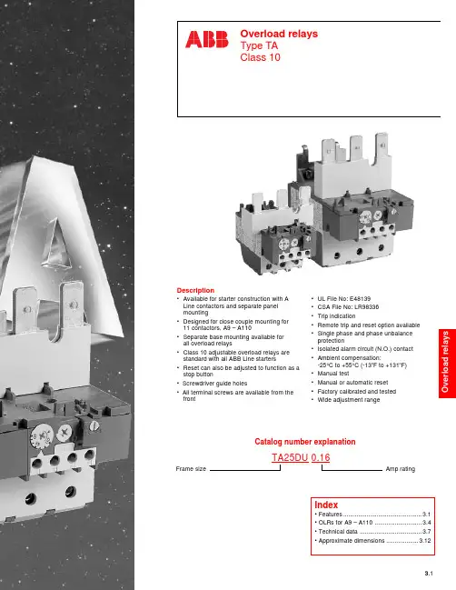
A C1030– 6/98ABB Control Inc.3.1OVERLOAD RELAYS:General info: 3.1 – 3.2Description•Available for starter construction with A Line contactors and separate panel mounting•Designed for close couple mounting for 11 contactors, A9 – A110•Separate base mounting available for all overload relays•Class 10 adjustable overload relays are standard with all ABB Line starters•Reset can also be adjusted to function as a stop button• Screwdriver guide holes• All terminal screws are available from the front•UL File No: E48139•CSA File No: LR98336•Trip indication•Remote trip and reset option available •Single phase and phase unbalance protection•Isolated alarm circuit (N.O.) contact •Ambient compensation:-25°C to +55°C (-13o F to +131o F)•Manual test•Manual or automatic reset •Factory calibrated and tested •Wide adjustment rangeFrame sizeAmp ratingCatalog number explanationTA25DU 0.16A C 1030 – 6/98ABB Control Inc.3.3OVERLOAD RELAYS:General info: 3.1 – 3.2Selection: 3.3 – 3.4Accessories: 3.5 – 3.6Technical data: 3.7 – 3.10Dimensions: 3.11 – 3.12Selection guide for Overload relaysThermal O/L relaysTypesTA25DU TA42DU TA75DU TA80DUSelection guideAC 1030 – 6/983.4ABB Control Inc.OVERLOAD RELAYS:General info: 3.1 – 3.2Selection: 3.3 – 3.4Accessories: 3.5 – 3.6Technical data: 3.7 – 3.10Dimensions: 3.11 – 3.12A C 1030 – 6/98ABB Control Inc.3.5OVERLOAD RELAYS:General info: 3.1 – 3.2Selection: 3.3 – 3.4Accessories: 3.5 – 3.6Technical data: 3.7 – 3.10Dimensions: 3.11 – 3.12Accessoriesfor Overload relaysDB25/25ADB80DB200LC26-B1Separate mounting kitsDiscount schedule TAA — TA25DescriptionLC terminal blocks can be used to convert standard connections into Faston connections: 2 x 6.3 mm or 4x 2.8mm per pole. The connections are protected against accidental contact.The LC30-T has a terminal block for the 3 power terminals and a second for the 4 auxiliary terminals of a TA25 DU thermal O/L relay.The LC26-B1 has two identical terminal blocks each for 3 power terminals. This block allows the power terminals to be mounted with two DB25 kits or a TA25DU thermal O/L relay and DB25 kit assembly.NOTE: According to DIN 46429 part 1 and NFC 20-120 the max. capacity of a Faston connection is 25A.AccessoriesAC 1030 – 6/983.6ABB Control Inc.OVERLOAD RELAYS:General info: 3.1 – 3.2Selection: 3.3 – 3.4Accessories: 3.5 – 3.6Technical data: 3.7 – 3.10Dimensions: 3.11 – 3.12Accessoriesfor Overload relaysDS25ADR25AApplication•The DS25-A coil is used for remote electrical tripping of the TA25 DU thermal O/L relay and is connected to the relay's normally closed 95-96 auxiliary contact.•The DR 25-A coil is used for remote electrical resetting of the TA25DU thermal O/L relay which is adjusted for "Manual resetting"; it is connected to the relay's normally open 97-98 auxiliary contact.The coils are not designed for continuous duty. Impulse duration: 0.2 to 0.35 s.Set the button to "Man" (Manual resetting).Mounting: clipped on to TA25DU thermal O/L relay.Installation diagramsFor connection of DS25-A to TA25DU relayFor connection of DR25-A to TA25DU relayRemote tripping coilsTRIPPING COILRESETTINGCOILRESETTINGCOILAccessoriesDiscount schedule TAA — TA25A C 1030 – 6/98ABB Control Inc.3.7OVERLOAD RELAYS:General info: 3.1 – 3.2Selection: 3.3 – 3.4Accessories: 3.5 – 3.6Technical data: 3.7 – 3.10Dimensions: 3.11 – 3.12Technical data for Overload relays TA25DU – TA110DUSwitching frequencyTo avoid nuisance tripping, TA and T thermal O/L relays have been designed to withstand roughly 15switching operations per hour with an approximately equal distribution between working and rest cycles.In these conditions, the motor starting time must not exceed 1 second and the starting current must be lower than or equal to 6 times the motor I n .For intermittent operations, the diagram opposite specifies relay operating limits.Example:Motor starting time:.................1 sec.Load factor:.............................40 %Switching frequency:...............60 ops./h according to diagramAmbient temperature compensationThermal O/L relays are compensated against ambient temperature variations by a compensation bimetal which is sensitive to the ambient temperature.Thermal O/L relays are designed to operate between –5°C and +40°C in compliance with standard IEC947-4-1.For a wider range of –25° C to +55 °C consult the graph opposite.Example: tripping at –25 °C. Tripping takes place before 1.5 times the setting current.Resetting: TA25DU – TA110DU thermal O/L relays have convertible manual/automatic resetting.Delivery: in manual resetting mode.Tripping limits at ambient temperatures varying by + 20°CM u l t i p l e o f t h e s e t t i n g c u r r e n tAmbient temperatureTechnical dataAC 1030 – 6/983.8ABB Control Inc.OVERLOAD RELAYS:General info: 3.1 – 3.2Selection: 3.3 – 3.4Accessories: 3.5 – 3.6Technical data: 3.7 – 3.10Dimensions: 3.11 – 3.12Technical data for Overload relays TA25DU – TA110DUPole characteristicsNumber of poles 3Setting rangessee page 3.4Tripping class according to IEC947–410A Operating frequency Hz0 – 400Tripping frequency Up to 15 ops./h or 60 ops./h with 40 % load factor when neither without untimely tripping the starting current of 6 x I n nor the starting time 1s are exceeded.Resistance per phase in m Ωand heat dissipation in Wsee page 3.9at the maximum current settingProtection fusesco-ordination with short circuit protection To be sized per NEC Article 430-152devices1On a support at an angle of ±30° in relation to the vertical plane (standard position). Other positions possible except mounting on a horizontal plane (in this case the tripping mechanism would be located above the bimetals).2 All the terminals are protected against direct contact according to VDE0106/Part. 100. (without additional terminal shrouds).3 All the terminals are protected against direct contact according to VDE0106/Part. 100. (with additional terminal shrouds).Technical dataA C 1030 – 6/98ABB Control Inc.3.9OVERLOAD RELAYS:General info: 3.1 – 3.2Selection: 3.3 – 3.4Accessories: 3.5 – 3.6Technical data: 3.7 – 3.10Dimensions: 3.11 – 3.12Technical data for Overload relays TA25DU – TA110DUAuxiliary contacts Normally Closed N.C.Normally Open N.O.Terminal marking95 – 9697 – 97Rated insulation voltage U iVAC 500500Conventional thermal current (in free air) I th A 106Rated operation current I e' AC-15up to 240V A 3.0 1.5up to 440V A 1.90.95up to 500V A 1.00.75Rated operational current I e DC-13up to 250V A 0.120.04Protection against short circuits gG (gl) fuses (according to IEC269A 106S271/S 281 circuit breakerA k3k1Maximum potential differenceVAC 500500between N.C. and N.O. auxiliary contactsVDC440440Resistance and Joule Loss per phaseTA42DU Thermal O/L relayTA25DU Thermal O/L relayTechnical dataAC 1030 – 6/983.10ABB Control Inc.OVERLOAD RELAYS:General info: 3.1 – 3.2Selection: 3.3 – 3.4Accessories: 3.5 – 3.6Technical data: 3.7 – 3.10Dimensions: 3.11 – 3.12T r i p p i n g t i m eM i n u t e sTripping currentin multiples of the setting current S e c o n d s0.8123456789101.21.5T r i p p i n g t i m eM i n u t e sTripping currentin multiples of the setting current S e c o n d s1201008060402010108686442210.8123456789101.21.5T r i p p i n g t i m eM i n u t e sTripping currentin multiples of the setting currentS e c on d s1201008060402010108686442210.8123456789101.21.5Technical dataA C 1030 – 6/98ABB Control Inc.3.11OVERLOAD RELAYS:General info: 3.1 – 3.2Selection: 3.3 – 3.4Accessories: 3.5 – 3.6Technical data: 3.7 – 3.10Dimensions: 3.11 – 3.12TA25DUTA42DUTA75DU & TA80DUTA110DUAC 1030 – 6/983.12ABB Control Inc.OVERLOAD RELAYS:General info: 3.1 – 3.2Selection: 3.3 – 3.4Accessories: 3.5 – 3.6Technical data: 3.7 – 3.10Dimensions: 3.11 – 3.12TA25DU & AB25TA25DU32 & AB32TA42DU / TA75DU & AB80A。
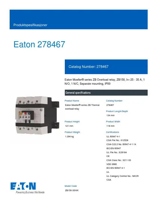
Eaton 278467Eaton Moeller® series ZB Overload relay, ZB150, Ir= 25 - 35 A, 1 N/O, 1 N/C, Separate mounting, IP00General specificationsEaton Moeller® series ZB Thermal overload relay278467134 mm121 mm 118 mm 1.394 kgUL 60947-4-1 CSA File No.: 012528 CSA-C22.2 No. 60947-4-1-14 IEC/EN 60947 UL File No.: E29184 CECSA Class No.: 3211-03 VDE 0660 IEC/EN 60947-4-1 ULUL Category Control No.: NKCR CSAZB150-35/KKProduct NameCatalog Number Product Length/Depth Product Height Product Width Product Weight Certifications Model CodeReset pushbutton manual/autoPhase-failure sensitivity (according to IEC/EN 60947, VDE 0660 Part 102) Test/off button Trip-free release-25 °C55 °C-25 °C40 °C CLASS 10 A Damp heat, constant, to IEC 60068-2-78 Damp heat, cyclic, to IEC 60068-2-30IP00ZB150Separate mounting Direct attachment25 A35 AIII3Finger and back-of-hand proof, Protection against direct contact when actuated from front (EN 50274)FeaturesAmbient operating temperature - min Ambient operating temperature - max Ambient operating temperature (enclosed) - min Ambient operating temperature (enclosed) - max Class Climatic proofingDegree of protection Frame size Mounting method Overload release current setting - min Overload release current setting - max Overvoltage category Pollution degree Product category ProtectionAccessoriesOverload relay ZB up to 150 A6000 V AC4000 V (auxiliary and control circuits)10 g, Mechanical, Sinusoidal, Shock duration 10 ms Branch circuits, (UL/CSA)Continuous≤ 0.25 %/K, residual error for T > 40°1 x (0.75 - 2.5) mm², Control circuit cables1 x (4 - 70) mm², Main cables2 x (4 - 70) mm², Main cables2 x (0.75 - 2.5) mm², Control circuit cables1 x (4 - 16) mm², Main cables2 x (4 - 16) mm², Main cables2 x (0.75 - 4) mm², Control circuit cables1 x (0.75 - 4) mm², Control circuit cables3/0, Main cables2 x (18 - 14), Control circuit cables1 x (16 - 70) mm², Main cables2 x (16 - 70) mm², Main cables24 mm8 mmM10, Terminal screw, Main cables5 mm AF, Hexagon socket-head spanner, Terminal screw, Main cablesM3.5, Terminal screw, Control circuit cables1 x 6 mm, Terminal screw, Control circuit cables, Standard screwdriver2, Terminal screw, Control circuit cables, Pozidriv screwdriver1.2 Nm, Screw terminals, Control circuit cables10 Nm, Screw terminals, Main cables6 A 5 kA, SCCR (UL/CSA)60 A Class J, max. Fuse, SCCR (UL/CSA)Rated impulse withstand voltage (Uimp)Shock resistanceSuitable forTemperature compensation Terminal capacity (flexible with ferrule)Terminal capacity (solid)Terminal capacity (solid/stranded AWG) Terminal capacity (stranded)Stripping length (main cable)Stripping length (control circuit cable) Screw sizeScrewdriver sizeTightening torqueConventional thermal current ith of auxiliary contacts (1-pole, open)Rated operational current (Ie) at AC-15, 120 V Short-circuit current rating (basic rating) Short-circuit protection rating1.5 A1.5 A0.9 A0.4 A0.2 A0.9 A0.75 A1000 V440 V, Between auxiliary contacts and main contacts, According to EN 61140240 V AC, Between auxiliary contacts, According to EN 61140 440 V AC, Between main circuits, According to EN 61140B600 at opposite polarity, AC operated (UL/CSA)R300, DC operated (UL/CSA)B300 at opposite polarity, AC operated (UL/CSA)600 VAC 100 A gG/gL, Fuse, Type “2” coordination125 A gG/gL, Fuse, Type “1” coordinationMax. 6 A gG/gL, fuse, Without welding, Auxiliary and control circuits111121 W0 W7 W35 A0 WMeets the product standard's requirements.Meets the product standard's requirements.Meets the product standard's requirements.Meets the product standard's requirements.Rated operational current (Ie) at AC-15, 220 V, 230 V, 240 V Rated operational current (Ie) at AC-15, 380 V, 400 V, 415 V Rated operational current (Ie) at DC-13, 110 VRated operational current (Ie) at DC-13, 220 V, 230 V Rated operational current (Ie) at DC-13, 24 VRated operational current (Ie) at DC-13, 60 VRated operational voltage (Ue) - maxSafe isolationSwitching capacity (auxiliary contacts, pilot duty) Voltage rating - max Number of auxiliary contacts (change-over contacts)Number of auxiliary contacts (normally closed contacts) Number of auxiliary contacts (normally open contacts) Number of contacts (normally closed contacts)Number of contacts (normally open contacts)Equipment heat dissipation, current-dependent PvidHeat dissipation capacity PdissHeat dissipation per pole, current-dependent PvidRated operational current for specified heat dissipation (In) Static heat dissipation, non-current-dependent Pvs10.2.2 Corrosion resistance10.2.3.1 Verification of thermal stability of enclosures10.2.3.2 Verification of resistance of insulating materials to normal heat10.2.3.3 Resist. of insul. mat. to abnormal heat/fire by internal elect. effectsMeets the product standard's requirements.Does not apply, since the entire switchgear needs to be evaluated.Does not apply, since the entire switchgear needs to be evaluated.Meets the product standard's requirements.Does not apply, since the entire switchgear needs to be evaluated.Meets the product standard's requirements.Does not apply, since the entire switchgear needs to be evaluated.Does not apply, since the entire switchgear needs to be evaluated.Is the panel builder's responsibility.Is the panel builder's responsibility.Is the panel builder's responsibility.Is the panel builder's responsibility.Is the panel builder's responsibility.The panel builder is responsible for the temperature rise calculation. Eaton will provide heat dissipation data for the devices.Is the panel builder's responsibility. The specifications for the switchgear must be observed.eaton-tripping-zb-overload-relay-characteristic-curve.epsDA-DC-00004845.pdfDA-DC-00004855.pdfDA-CE-ETN.ZB150-35_KKIL03407006ZDA-CD-zb150_kkDA-CS-zb150_kkeaton-tripping-devices-overload-relay-zb-overload-relay-dimensions-007.epseaton-tripping-devices-overload-relay-zb-overload-relay-3d-drawing-005.eps10.2.4 Resistance to ultra-violet (UV) radiation10.2.5 Lifting10.2.6 Mechanical impact10.2.7 Inscriptions10.3 Degree of protection of assemblies10.4 Clearances and creepage distances10.5 Protection against electric shock10.6 Incorporation of switching devices and components 10.7 Internal electrical circuits and connections10.8 Connections for external conductors10.9.2 Power-frequency electric strength10.9.3 Impulse withstand voltage10.9.4 Testing of enclosures made of insulating material 10.10 Temperature rise10.11 Short-circuit rating10.12 Electromagnetic compatibility Characteristic curve Declarations of conformity eCAD model Installeringsinstruksjoner mCAD modelTegningerEaton Corporation plc Eaton House30 Pembroke Road Dublin 4, Ireland © 2023 Eaton. Med enerett. Eaton is a registered trademark.All other trademarks areproperty of their respectiveowners./socialmediaIs the panel builder's responsibility. The specifications for the switchgear must be observed.The device meets the requirements, provided the information in the instruction leaflet (IL) is observed.10.13 Mechanical function。
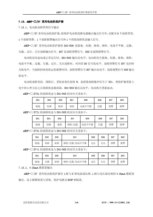
7.15、AMDP-□/D7 系列电动机保护器7.15.1、电动机故障类型信号输出AMDP-□/D7系列电动机保护器,除保护电动机的继电器触点输出信号外,还配有6个故障类型、1个故障预警、1个故障报警输出信号和1个清除故障状态输入信号。
AMDP-□/D7 系列电动机保护器的DO1-DO6是接地、短路、缺相、堵转、电流不平衡、过载、欠载、过压、欠压故障输出信号,DO7是故障预警信号,DO8是故障报警信号。
电动机没有起动或正常运行时,DO1-DO8输出高电平;电动机发生接地、短路、缺相、堵转、电流不平衡、过载、欠载、过压、欠压故障时,对应的DO信号低电平,故障预警信号DO7也同时为低电平,当故障持续到设定的报警时间,故障预警信号DO7输出高电平,故障报警信号DO8输出低电平。
电动机故障查清、排除后,采取按复位按钮R、加清除故障脉冲信号于DI1、使保护器重新上电中的1种方法之后故障状态被清除,DO1-DO8输出高电平,电动机可重新起动。
AMDP-□/D701的故障状态与DO1-DO8的对应关系如下:DO1 DO2 DO3 DO4 DO5 DO6 DO7 DO8接地 短路 缺相 堵转 电流不平衡 过载 预警 报警 AMDP-□/D721的故障状态与DO1-DO8的对应关系如下:DO1 DO2 DO3 DO4 DO5 DO6 DO7 DO8接地 短路 缺相 堵转/过载电流不平衡欠载 预警 报警 AMDP-□/D731的故障状态与DO1-DO8的对应关系如下:DO1 DO2 DO3 DO4 DO5 DO6 DO7 DO8接地 短路 缺相 堵转/过载/电流不平衡过压 欠压 预警 报警 AMDP-□/D741的故障状态与DO1-DO8的对应关系如下:DO1 DO2 DO3 DO4 DO5 DO6 DO7 DO8接地 欠载 缺相 堵转/过载/电流不平衡过压 欠压 预警 报警7.15.2、4-20mA模拟量输出AMDP-□/D7 系列电动机保护器有1路与C相电流成比例、1路与电压成比例的4-20mA模拟量输出,这2路模拟量与采集、保护电路及DSP相隔离。

漏电保护器使用说明书漏电保护器,简称漏电开关,又叫漏电断路器,主要是用来在设备发生漏电故障时以及对有致命危险的人身触电保护,具有过载和短路保护功能,可用来保护线路或电动机的过载和短路,亦可在正常情况下作为线路的不频繁转换启动之用。
国家为了规范漏电保护器的正确使用,相继颁布了《漏电保护器安全监察规定》(劳安字(1999)16号)和《漏电保护器安装与运行(GB13955-92)等一系列标准和规定。
依据这些标准和规定,我们在选用漏电保护器时应遵循以下主要原则:1. 购买漏电保护器时应购买具有生产资质的厂家产品,且产品质量检测合格。
在这里要提醒大家:市场上销售的漏电保护器有不少是不合格品。
2002年10月28日,国家质检总局公布漏电保护器产品质量抽查结果,有20%左右的产品不合格,其主要问题为:有的不能正常分断短路电流,消除火灾隐患;有的起不到人身触电的保护作用;还有一些不该跳闸时跳闸,影响正常用电。
2. 应根据保护范围、人身设备安全和环境要求确定漏电保护器的电源电压、工作电流、漏电电流及动作时间等参数。
3. 电源采用漏电保护器做分级保护时,应满足上、下级开关动作的选择性。
一般上一级漏电保护器的额定漏电电流不小于下一级漏电保护器的额定漏电电流,这样既可以灵敏地保护人身和设备安全,又能避免越级跳闸,缩小事故检查范围。
4. 手持式电动工具(除III类外)、移动式生活用家电设备(除III 类外)、其他移动式机电设备,以及触电危险性较大的用电设备,必须安装漏电保护器。
5. 建筑施工场所、临时线路的用电设备,应安装漏电保护器。
这是《施工现场临时用电安全技术规范》(JGJ46-88)中明确要求的。
6. 机关、学校、企业、住宅建筑物内的插座回路,宾馆、饭店及招待所的客房内插座回路,也必须安装漏电保护器。
7. 安装在水中的供电线路和设备以及潮湿、高温、金属占有系数较大及其他导电良好的场所,如机械加工、冶金、纺织、电子、食品加工等行业的作业场所,以及锅炉房、水泵房、食堂、浴室、医院等场所,必须使用漏电保护器进行保护。
ES10系列电动机保护器使用说明书江阴市东歌电气技术有限公司目录1.产品简介 (2)1.1概述 (2)1.2主要性能 (2)1.3引用标准 (2)2.保护器订购选型说明 (3)3.保护器面板及接线端子说明 (4)3.1保护器正面布置 (4)3.2保护器的端子功能 (5)4.ES102编程器功能说明 (6)4.1指示灯功能 (7)4.2 ES102按键功能 (7)4.3 参数设定和查询 (7)4.4故障代码的含义 (19)4.5 符号对照表 (20)5.典型应用接线图 (21)1.产品简介1.1概述ES10系列电动机保护器对电动机的过载、欠载、缺相不平衡、堵转、过热、欠压、过压、接地或漏电等故障引起对电动机的危害给予以系统保护,可实现多种操作控制功能,同时具有测量、自我诊断、维护管理、现场总线通讯等功能。
1.2 主要性能额定工作电压:AC220V/AC380V,消耗功能15W。
电机工作电压:AC380V、660V,50Hz。
额定电流:2A(0.5A~2A);5A(1A~5A);6.3A(1.6A~6.3A);25A(6.3A~25A);100A(25A~100A);250A(63A~250A)。
继电器输出:输出使用继电器隔离,继电器触点额定负载容量a)阻性负载:AC220V(250V)、5A、COSΦ=1,DC24V(30V)、5A。
b)感性负载:AC:AC220V、1.6A ; DC:DC24V 、2A 。
工作环境a)周围环境温度不高于+55℃,不低于-10℃。
b)安装的海拔不超过2500m。
c)污染等级2级。
d)安装类别Ⅲ。
1.3引用标准:本产品符合GB/T14048.1、GB 14048.4、GB/T 17626.2/3/4/5中有关规定。
2.保护器订购选型说明附加功能表1产品代号 表33.保护器面板及接线端子3.1保护器布置图A相B相C相 V通讯运行报警故障编程口%In东歌EASTSONGES-101功能运行signal in注:1: 端子(功能详解见3.2)2: 指示灯:通讯指示灯,在通讯建立后恒亮。

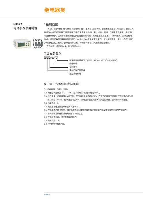
NJBK7电动机保护继电器1 适用范围2 型号及含义N JBK7电动机保护继电器(以下简称保护器),适用于交流50Hz、额定绝缘电压至690V以下,额定工作电流80A-800A的长期工作或间断工作的交流电动机的过载、堵转、断相、三相电流不平衡、接地及P Tc温度等保护。
该保护器采用柔性的罗氏线圈采集电流,具有整定电流范围广,精确度高、安装方便等优点。
该保护器同时具有RS485接口、4mA-20mA模拟量变送接口,可以组网通信,通过上位机对电机实现远程监视、控制,故障查询等功能。
保护器一般与交流接触器配合使用。
符合标准:GB 14084.4、IEC 60947-4-1。
额定控制电源电压(AC220、AC380、AC/DC100V-240V)规格代号设计序号电动机保护继电器企业特征代号N JBK 7-800 /□3 正常工作条件和安装条件3.2 周围空气温度为-5℃~+40℃,且24h内的平均值不超过+35℃。
3.3 大气条件:最高温度为+40℃时,空气相对湿度不超过50%,在较低的温度下可以允许有较高的相对湿 度,例如+20℃时,空气湿度可达90%,并对由于温度变化偶尔产生的凝露,应采取特殊的措施。
3.4 污染等级:3。
3.5 安装面与垂直面的倾斜度不大于±5°。
3.6 在无爆炸危险介质中,且介质中无足以腐蚀金属和破坏绝缘的气体及较多导电尘埃存在的地方。
3.7 在有防雨雪设备及没有充满水蒸气的地方。
3.8 在无显著摇动、冲击和振动的地方。
3.9 安装类别:Ⅲ。
3.10 外壳防护等级:IP20。
3.1 海拔高度:不超过2000m。
4.2 辅助电路:额定绝缘电压AC380V,额定频率50Hz,辅助触点参数型号NJBK7-800/□整定电流(A)800整定电流范围(A)80-800适合电动机功率(kW)40-400使用类别额定工作电压Ue(V)额定工作电流Ie(A)约定发热电流Ith(A)AC-152401.53800.9554 主要参数及性能4.1 主电路:额定绝缘电压AC690V,额定频率50Hz 4.3 结构特点4.3.1 分体安装;4.3.2 L CD显示,按键设定;4.3.3 具有启动延时功能;4.3.4 具有故障记忆功能,能查询故障记录;4.3.5 具有RS485接口,支持MODBUS协议,可组网通讯;5.2 断相保护动作特性主电路三相电流任意一相电流为零时,保护器动作,动作时间≤5s。
过载保护的概念过载保护顾名思义即载荷(负载)超出某一限定值,为了维护机器及设备的安全而进行的保护。
我们所指的过载保护装置主要是针对于机器和设备的扭矩进行保护的扭矩限制器、扭矩保持器、对机器及设备轴向载荷(包括拉力和推力)过载进行保护的直线限力器,对电机过载进行保护的电气式过载保护器扭矩限制器又称安全离合器、安全联轴器,常用于安装在动力传动的主、被动侧之间,当发生过载故障时(扭矩超过设定值),扭矩限制器便会产生分离,从而有效保护了驱动机械(如电机、减速机、伺服马达)以及负载,常见形式为:磨擦式扭矩限制器以及滚珠式扭矩限制器。
扭矩限制器的安装结构形式有:轴-轴、轴-法兰、轴-同步带轮、轴-链轮、轴-齿轮、轴-带轮等。
扭矩保持器也称扭力控制器、滑动联轴器。
常用于安装在动力传动的驱动侧和负载侧之间,一旦传递扭矩达到设定值,扭矩保持器便会产生打滑,从而使动力传动的主、被动侧以固定扭矩值传递动力。
主要用于需要提供定扭矩值的间歇性滑移工况以及收放卷时的张力控制。
直线限力器是对机器及设备直线方向载荷(包括拉力和推力)过载进行保护的过载保护装置。
联接在同一直线上的主、被动机构之间,一旦主、被动侧间拉力或推力超出限定值,主、被动侧间动力瞬间完全卸载,防止了轴向载荷过载故障导致的停机和损伤。
电式的过载保护器是通过监视电流而迅速检测出电机过载。
它不同于电机的过载保护器如热继电器、熔断器等,而是用于设备保护的过载保护器。
与热继电器相比其反应时间更为迅速,不到其反应时间的1/5,电机过载保护器的电流在稍微超过预设电流时不会动作,即使工作其动作也会很缓慢。
过载保护的类别及特点工作原理分:一机械式过载保护器1 扭矩限制器A 滚珠型扭矩限制器特点:滚珠式(钢球式)过载保护器,其制造简单,工作可靠,过载时滑动摩擦力矩小(有的几乎没有),动作灵敏度高,自动恢复精度高,其结构形式也是最丰富的,是自动化工业生产的理想产品。
B 摩擦型扭矩限制器特点:摩擦式过载保护器,过载时因摩擦消耗能量缓和冲击,故工作平稳、调整和使用方便、维修简单、灵敏度较高,过载消除后即自动恢复,用于转速高,转动惯量大的传动装置,是目前使用比较广泛的产品。
1.3.5 安装面与垂直面的斜度不大于±5°。
1.3.6 在无爆炸危险介质,且介质中无足以腐蚀金属和破坏绝缘的气体及较多导电尘埃存在的地方。
1.3.7 在有防雨雪设备及没有充满水蒸汽的地方。
1.3.8 在无显著动摇、冲击和振动的地方。
1.3.9 安装类别:Ⅲ。
1.3.10 主电路使用类别:AC-3、AC-4。
2.1 结构本系列电动机保护器主要部件由底座罩壳、互感器和电路板组件组成。
全部的零部件都安装在一个塑料外壳中。
2.2 结构特点2.2.1 保护器具有断相和过载保护功能。
2.2.2 保护器的三个指示灯分别指示运行、过载和断相工作状态。
2.2.3 保护器具有整定电流连续可调装置。
2.2.4 保护器的主电路是采用穿芯式接线方试。
2.2.5 保护器的脱扣级别:10A ;3P 。
2.2.6 保护器的安装方式:与产品底板平面螺钉独立安装。
2.3 工作原理保护器是通过电流互感器检测电动机主电路电流来判断电动机是否过载或断相的,过载时触发过载反时限电路,根据过载电流倍数进行延时,延时时间到,便触发继电器使其常闭触头断开而实现保护;断相时保护器是通过断相保护电路延时,时间到,则使继电器常闭触头断开而实现保护。
2 结构与工作原理3.1 主电路基本参数见表13.2 辅助电路技术参数3.2.1 额定工作电压AC220V ±10%或AC380V ±10%,3 技术参数1.1适用范围JD-5(B)电动机保护器,适用于额定频率50Hz ,额定工作电压AC380V/AC220V ,额定工作电流0.5A~100A 的长期工作1 概述:额定控制电源电压:以电压值AC380V 或AC220V 表示整定电流范围代号(见表1),用整定电流范围最大值表示基本规格代号:不标注为一般式,加注字母B 表示设有报警功能设计序号电动机保护器1.3正常工作条件1.3.1周围空气温度:a) 周围空气温度不超过+40℃,且其24h 内其平均温度值不超过+35℃;b) 周围空气温度下限为-5℃。
XD-40配置SIEMENS802D数控系统操作说明书XD-40数控铣床电⽓使⽤说明书(SINUMERIK 802D系统)中华⼈民共和国⼤连机床集团有限责任公司序⾸先感谢您使⽤本公司的产品,我们深信您所购买的产品具有坚实与⾼精度的品质,配合适当的维护,在未来的时间⾥,将带给您更优越的加⼯产品品质。
由于本公司持续不断地提⾼产品性能,同时您也可能有特殊要求,因此您可能会发现送达贵公司的机床与本⽂件有些差异,此仅表⽰新的改善⽅案已运⽤到您的机床上。
如有任何问题,请随时与本公司联系。
说明书中的所有附图与画⾯,均只是⽤于图解说明,有助于⽤户了解。
说明书中并不提供所有构件的实际尺⼨或公差值。
本公司有对本产品、机床规格及各种机床⽂件进⾏修改或完善的权利,没有告知先前使⽤者这些修正或改善的义务。
本机床所有随机⽂件在未得到本公司书⾯同意前,不得以任何形式或⽅法来重新制作、翻印或影印。
本公司保留上述有关权利。
⽬录1、电⽓安全2、机床电⽓概述3、机床操作概述4、机床编程概述5、机床电⽓维修概述6、部分参数的设定1.1 安全预防本机床安装有许多安全设置,以避免遭受伤害或破坏,操作者不能仅依赖于本机床的这些保护装置,⽽应该了解以下各章节说明后,⽅可进⾏操作和维修。
切不可随意操作、维修机床。
否则将⼤⼤增加个⼈伤害、机床损伤的可能性。
经过对本⼿册的阅读以及结合您对机床操作的常识及经验,将会降低⾮加⼯时间、提升⽣产效率及提⾼操作机床的安全性。
因在特殊运⽤的场合⽽附加的安全因素必须加以考虑,请参考相关的安全作业规章制度。
重要守则★未经培训的⼈员禁⽌维护或操作本机床;★禁⽌操作⼯尝试维修本机床;★请谨慎⼯作并随时注意安全。
如您⾝体已受药物或酒精的影响,请勿操作或维修本机床;★请勿使⽤压缩空⽓直接对着控制⾯板、电⽓箱喷吹;★必须知道“紧急停⽌按钮”所在位置;★如发⽣停电,应⽴即关闭总电源;★请勿改变参数、数量及其它设定值。
如有必要更改,请修正前先记录相关改动;★请勿让机床在⽆⼈看护下运转;★每⽇⼯作结束后,请将主电源关闭;1.2 电⽓安全装置及作⽤在特别留意上述章节之安全建议外,请了解以下安全装置及其作⽤,以保证机床的正常运转和⼈⾝安全。
Z B T-11型高开综合保护器(V e r3.0)使用说明书上海山源电子电气科技发展有限公司二零零七年一月感谢您选择上海山源电子电气科技发展公司研发的ZBT-11系列井下高压综合保护器,为方便你选购和安全、正确、高效的使用本保护器,请仔细阅读本说明书并在使用时务必注意以下几点。
注意:●保护器外壳应可靠接地;●禁止带电插拔通讯插头;●配套的高爆开关的断路器机构类型是否与保护器出厂铭牌一致;●电流输入极性是否正确,电压输入相序是否正确;●核对保护器的定值是否输入正确;●保护器的工作电源为AC100V。
目录1产品简介 (5)2产品特点 (5)3功能简介 (6)3.1保护功能 (6)3.2测量监测功能 (6)3.3事件记录及故障录波功能 (6)3.4开关控制功能 (6)3.5电度脉冲测量和累计 (6)3.6就地显示功能 (6)4技术指标 (6)4.1工作环境要求 (6)4.2工作电源 (7)4.3保护参数 (7)4.3.1电流保护元件 (7)4.3.2漏电电流保护元件 (7)4.3.3过(低)电压保护元件 (7)4.3.4双屏蔽电缆监视保护元件 (7)4.3.5反时限保护 (7)4.3.6动作时间准确度 (8)4.3.7通信接口 (8)5操作简介 (8)5.1KJS9红外遥控器 (8)5.2显示器布局图 (9)5.3操作指南 (9)5.3.1正常显示界面 (10)5.3.2主菜单 (11)5.3.3装置操作 (11)5.3.4事件查询 (12)5.3.5数据查询 (13)5.3.6装置管理 (15)6定值使用说明 (19)6.1定值清单 (19)6.2定值整定说明 (19)6.3定值整定注意事项 (20)7常见故障分析 (23)8用户安装调试,维护说明 (23)8.1注意事项 (23)8.2保护器的安装示意图 (24)9附图 (24)1产品简介ZBT-11系列高开综合保护器(以下简称保护器),是我公司根据用户和厂商需求精心研制并成功开发的新一代高开综合保护器。
漏电保护器使用说明书漏电保护器,简称漏电开关,又叫漏电断路器,主要是用来在设备发生漏电故障时以及对有致命危险的人身触电保护,具有过载和短路保护功能,可用来保护线路或电动机的过载和短路,亦可在正常情况下作为线路的不频繁转换启动之用。
国家为了规范漏电保护器的正确使用,相继颁布了《漏电保护器安全监察规定》(劳安字(1999)16号)和《漏电保护器安装与运行(GB13955-92)等一系列标准和规定。
依据这些标准和规定,我们在选用漏电保护器时应遵循以下主要原则:1. 购买漏电保护器时应购买具有生产资质的厂家产品,且产品质量检测合格。
在这里要提醒大家:市场上销售的漏电保护器有不少是不合格品。
2002年10月28日,国家质检总局公布漏电保护器产品质量抽查结果,有20%左右的产品不合格,其主要问题为:有的不能正常分断短路电流,消除火灾隐患;有的起不到人身触电的保护作用;还有一些不该跳闸时跳闸,影响正常用电。
2. 应根据保护范围、人身设备安全和环境要求确定漏电保护器的电源电压、工作电流、漏电电流及动作时间等参数。
3. 电源采用漏电保护器做分级保护时,应满足上、下级开关动作的选择性。
一般上一级漏电保护器的额定漏电电流不小于下一级漏电保护器的额定漏电电流,这样既可以灵敏地保护人身和设备安全,又能避免越级跳闸,缩小事故检查范围。
4. 手持式电动工具(除III类外)、移动式生活用家电设备(除III 类外)、其他移动式机电设备,以及触电危险性较大的用电设备,必须安装漏电保护器。
5. 建筑施工场所、临时线路的用电设备,应安装漏电保护器。
这是《施工现场临时用电安全技术规范》(JGJ46-88)中明确要求的。
6. 机关、学校、企业、住宅建筑物内的插座回路,宾馆、饭店及招待所的客房内插座回路,也必须安装漏电保护器。
7. 安装在水中的供电线路和设备以及潮湿、高温、金属占有系数较大及其他导电良好的场所,如机械加工、冶金、纺织、电子、食品加工等行业的作业场所,以及锅炉房、水泵房、食堂、浴室、医院等场所,必须使用漏电保护器进行保护。