ARMSTRONG DE 智能变频泵介绍
- 格式:ppt
- 大小:17.99 MB
- 文档页数:78

阿姆斯壮泵工作原理
阿姆斯壮泵是一种智能变频水泵,其工作原理是通过内置PSPC控制技术,控制水泵启停及运行台数,从而在满足系统需求的情况下,使泵组在最佳能效状态下运行,达到系统所需流量。
阿姆斯壮智能变频水泵采用了优秀的自控方法,能够较好地解决生产线负荷波动较大的问题,使水泵运行更加高效。
这种智能变频水泵可以显示瞬时的流量、扬程、功率、电流、频率等参数,并具有手动设定流量、扬程、频率等功能,还具有3个运行模式:泵出口恒压、远端恒压差、恒流量。
阿姆斯壮泵的工作原理为水泵行业的创新和发展提供了新的思路和方向。
泽德商用智能双泵提升泵说明书泽德商用智能双泵提升泵是一种用于提升和排水的机械设备。
本说明书将详细介绍该泵的特点、结构、使用方法和注意事项。
一、特点:1. 智能控制:采用智能控制系统,可以实现自动运行和自动停机,提高了泵的使用便利性和安全性。
2. 双泵结构:该泵采用双泵结构,可以提高提升和排水的效率,同时也增加了泵的使用寿命。
3. 高效性能:配备强力电机和优质叶轮,能够快速将水提升至目标位置,并具有较高的排水能力。
4. 耐用材料:该泵采用优质不锈钢材料制造,具有较高的耐腐蚀性和耐用性。
二、结构:1. 泵体:泵体采用不锈钢材料制造,具有稳定的结构和较高的耐腐蚀性。
2. 叶轮:叶轮采用高质量不锈钢制造,具有良好的涡轮设计,提高了泵的提升和排水能力。
3. 电机:配备高效电机,具有较高的功率和稳定的性能。
三、使用方法:1. 安装:将泵体固定在合适位置,确保泵与水源之间的连接管道正确连接。
2. 连接电源:将泵的电源线与电源插头连接,确保电源稳定。
3. 开启智能控制系统:根据实际需要设置智能控制系统的参数,确保泵的自动运行和停机功能正常。
4. 使用:打开水源阀门,启动泵进行提升和排水操作,根据实际需求控制水的流量和提升高度。
四、注意事项:1. 安装前请务必关闭电源,确保安装过程的安全性。
2. 在使用过程中,应定期检查泵体和连接管道的密封性,确保不存在漏水现象。
3. 在长时间不使用时,应将泵体和管道排空,防止积水导致泵的损坏。
4. 使用过程中如发生异常情况,应立即切断电源并进行检修。
本说明书提供了泽德商用智能双泵提升泵的详细介绍和使用方法,希望能够对用户正确使用该设备提供帮助。
如需更多信息,请参考产品说明书或与生产厂家联系。
神能多级变频水泵说明书神能多级变频水泵说明书神能多级变频水泵是一种高效、先进的水泵设备,主要用于供水、排水、冷却系统以及工业生产中的液体输送。
本说明书旨在为用户提供生动、全面、具有指导意义的操作指南,以确保用户能够正确、安全地操作和维护神能多级变频水泵。
一、产品概述和特点神能多级变频水泵采用先进的变频技术,能够根据实际使用需求自动调节运行频率,从而提高能效和节能效果。
其特点如下:1. 高效节能:采用变频控制技术,能够根据不同工况实时调节运行频率,最大程度地降低能耗。
2. 稳定可靠:采用优质材料和先进工艺制造,具有耐腐蚀、耐磨损和抗压性能,确保长期稳定运行。
3. 操作简便:智能化控制系统使得操作简单方便,用户只需进行简单设置即可实现自动控制和监测。
4. 安全保护:设有多重保护装置,如过载保护、过温保护和电压保护,确保设备安全运行。
5. 多种应用场景:适用于家庭供水、建筑排水、农田灌溉、工业生产和循环水系统等多个领域。
二、操作指南1. 安装:根据具体需求选择合适的安装位置,确保水泵稳固且离地面垂直。
安装过程中请确保供电线路正确接入,接地良好。
2. 启动:将电源插头插入插座后,按下开关启动水泵。
在启动过程中,请留意是否存在异常声音或振动。
3. 设置运行参数:根据实际需求,设置水泵的运行参数,包括运行频率、运行时间和运行模式等。
请参照附带的使用手册进行正确操作。
4. 监测运行状态:通过水泵自带的显示屏,可以实时监测水泵的运行状态,包括压力、温度和故障信息等。
如发现异常情况,请及时进行处理。
5. 停机:当水泵工作完成或需要停机时,按下停机按钮,等待水泵完全停止后再进行其他操作。
三、维护保养1. 定期清洁:根据水泵使用情况,定期对水泵进行清洁,清除泵体和叶轮上的杂物和沉积物,以保证良好的工作效果。
2. 润滑保养:定期检查水泵的润滑系统,如油位是否正常、油质是否需要更换等,确保水泵正常运转。
3. 检修维护:定期对水泵进行全面检修和维护,包括电气系统、机械传动系统和密封系统等,确保设备的长期稳定运行。
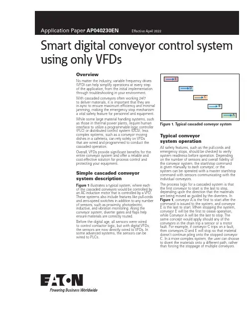
Smart digital conveyor control system using only VFDsOverviewNo matter the industry, variable frequency drives (VFD) can help simplify operations at every stepof the application, from the initial implementation through troubleshooting in your environment. With cascaded conveyors often working 24/7to deliver materials, it is important that they arein-sync to ensure maximum efficiency and minimal jamming, making the emergency stop mechanism a vital safety feature for personnel and equipment. While some large material handling systems, such as those in thermal power plants, require human interface to utilize a programmable logic controller (PLC) or distributed control system (DCS), less complex systems, such as a conveyor moving dishes in a cafeteria, can rely solely on VFDsthat are wired and programmed to conduct the cascaded operation.Overall, VFDs provide significant benefits for the entire conveyor system and offer a reliable and cost-effective solution for process control and protecting your equipment.Simple cascaded conveyor system descriptionFigure 1 illustrates a typical system, where eachof the cascaded conveyors would be controlled by an AC induction motor that is controlled by a VFD. These systems also include features like pull-cords and zero-speed switches in addition to any number of sensors, such as proximity, photoelectric, inductive, and vibration monitoring. Along the conveyor system, diverter gates and flaps help ensure materials are correctly routed.Before the digital age, all sensors were wiredto control contactor logic, but with digital VFDs, the sensors are now directly wired to VFDs. In some advanced systems, the sensors can be wired to PLCs.Figure 1. T ypical cascaded conveyor system Typical conveyorsystem operationAll safety features, such as the pull-cords and emergency stops, should be checked to verify system readiness before operation. Depending on the number of sensors and overall fidelity of the conveyor system, the start/stop commandis given manually to each conveyor, or the system can be operated with a master start/stop command with sensors communicating with the individual conveyors.The process logic for a cascaded system is that the first conveyor to start is the last to stop, depending upon the direction that the materials are being moved as guided by the diverters. In Figure 1, conveyor A is the first to start after the command is issued to the system, and conveyor E is the last to start. When stopping the system, conveyor E will be the first to cease operation, while Conveyor A will be the last to stop. The same concept would apply should any of the conveyors in the chain trip a sensor or a motor fault. For example, if conveyor C trips on a fault, then conveyors D and E will stop so that material doesn’t continue piling onto the stopped conveyor C. In a more complex system, the user can choose to divert the materials onto a different path, rather than forcing the stoppage of multiple conveyors.2Application Paper AP040230ENEffective April 2022Smart digital conveyor control systemusing only VFDsEATON Understanding sensor integrationThe most common sensor used in conveyor systems is a zero-speed switch, which provides feedback as to whether the conveyor is moving or has stopped. While an AC induction motor could be moving because VFDs are putting out voltage, the conveyor could actually be stopped. In that case, the zero-speed switch senses the actual movement—or lack thereof—coming from the conveyor belt. In Figure 1, if the zero-speed switch on conveyor C triggers, then the motors on conveyors C, D, and E will stop to prevent materials from piling up and accidental damage.It is important with the implementation of a zero-speed switch in the controls to begin sensing after the conveyor has started running at a certain frequency, but not before the conveyor has started moving. If the zero-speed switch begins sensing before the conveyor is running, then it will never start.When VFDs were less advanced, PLCs were a must for implementing control of a cascaded conveyor system, and before PLCs, hardware-wired relay controls were used. With advancements in the applications offered by VFD digital controls, most of the control functions required by the simple conveyor system (Figure 1) can be achieved by integrating the sensors to, and in the wiring between, the VFDs. Using only VFDs, rather than integrating PLCs with them, is a more cost-effective solution for achieving the same performance.How to integrate a conveyor system digitally with VFDsFor the following section, refer to Figure 1.Start command: A total of five VFDs—one for each conveyor motor—are connected on the control board. Run feedback from conveyor A is wired to conveyor B, and conveyor B is wired to conveyor C, and so on until all conveyors are connected to one another. The start command is issued to conveyor A, and the run feedback starts conveyor B, while conveyor B starts conveyor C, and onward until conveyor E begins moving. This is how VFD controls start all five conveyors.Conveying speed reference control: The main system speed reference input is only fed to conveyor A ’s VFD. Then, all five of the conveyor’s VFDs feed the speed control signal, i.e., A > B > C > D > E. Changing the speed reference to conveyor A subsequently changes the speed of the conveyors upstream that feed material to conveyor A.Stop/fault command: Just like the start command, the stop/fault command works via the five VFDs connected to one another on the control board. When the stop command is issued, conveyor E will be the first to stop, which is wired to then pass the command to conveyor D, and onward through the cascaded conveyors, i.e., E > D > C > B > A. Each conveyor is wired to the next in the chain, which is how the VFD stops all five conveyors. The faultcommand follows the exact same sequence as the stop command.Sensor interface: Users add more sensors to the conveyor system as fidelity increases. The zero-speed switch for each conveyor is wired to its specific external fault, and if triggered, the VFD will issue a fault to automatically stop the subsequent VFDs in the chain. The zero-speed switch can be bypassed by using drive-relay before the drive is running by setting the drive frequency above that of the moving conveyor. Once the relay picks up the preset speed frequency, it arms the zero-speed input on the same channel as the relay for initial bypass of zero-speed sensing. Simple control is achieved by using VFD digital controls without the need for a PLC.The pull-cords of the conveyors can be wired in series to the STO of the drives. This is the safest way to put an emergency stop on the drives running the motor and is possible to achieve with only VFDs.Figure 2. T ypical relay wiring for zero-speed sensingProximity sensors: Proximity sensors can be connected to the VFDs for a more intelligent start/stop by sensing the materials on the conveyor. Instead of running the systems continuously, it can be started and stopped based on the load that is traveling on the conveyor. This power-saving option enables the VFD to give a start command to the next conveyor in the cascade, only in the event it needs to be activated.Referring again to Figure 1, the proximity sensor would detect a load on conveyor E, and as soon as the load reaches a preset point, it would give a start command to conveyor D and so on until it reaches conveyor A.The same logic applies to the stoppage of conveyors. If the load falls below a certain preset threshold, it triggers a command to the rest of the conveyor system that a load isn’t being transported, thus turning it off to save power.Maintenance management: Sensors with vibration monitoring capabilities can be wired directly to the VFD to trigger a warning and generate a fault command to prevent damage to the system.Use of DM1 for a conveyor applicationSelection of DM1 modelBased on motor current selected for the conveyor, the user can select the DM1 model that supports 150% of the overload. DM1 is available in models capable of 110% or 150% overload for 60 seconds, but the conveyor application requires constant torque. Because of that, the 150% overload model (also known as an IH model) is recommended.In certain applications, the drive is required to deliver 200% overload, and the DM1 can deliver at that level for 2 seconds, every 20 seconds. After delivering the required torque in the overloaded zone, the drive will safely trip if the load demands higher torque for an extended period of time.Power and control wiring of DM1The DM1 installation manual will help determine recommended fuse protection and cable sizes, based on frame size and model. The manual also contains recommendations for grounding, EMC, brake resistor, and control wiring. Users should follow the design guidelines from the manual.Figure 3 shows typical control wiring for the DM1.3Application Paper AP040230ENEffective April 2022Smart digital conveyor control system using only VFDs EATON Figure 3. T ypical control wiring schemePlanning fieldbus control for the conveyorAs illustrated above, the control can be wired to the drive. If the conveyor system has a PLC, the DM1 Pro model offers onboard EtherNet/IP connection or, as an option, a Profibus T card forcontrolling and reading drive data via fieldbus link. The Modbus T RTU is available with every model.Eaton has developed Add-On Instructions (AOIs) for Rockwell PLC that support various assemblies, allowing for simple import to the Rockwell Studio5000, and used in PLC programming for controlling start/stop and speed reference to the DM1 drive. AOI also supports the data read from the PLC. For protocols and application notes to support PLC code implementation, refer to the quick start guide.DM1 software features for controlling conveyors Motor controlMotor control mode: The conveyor application can be run using V/F scalar control or Sensorless Vector Control (SVC). In V/F control mode, DM1 can offer +/–0.5% of base speed across a 30:1 speed range. If the speed reference to the conveyor is changing frequently, SVC control is recommended, which will provide +/–0.5% speed accuracy across a 60:1 speed range for the application.Speed reference: DM1 offers fixed speed reference throughdigital inputs that can be preset for speed reference, or the speed references can be an analog input or Fieldbus control register. DM1 offers various speed acceleration and deceleration profiles built into the drive control algorithms that can be selected by the user to minimize the equipment wear and tear.Start/stop mode: Ramp start/stop applications are typically used for conveyors, but DM1 also offers flying-start if required.Because particular conveyor applications might require a fast start/stop, the minimum programmable deceleration rate offered by DM1 is one-tenth of a second (0.1), but due to load inertia, actual stop time will vary.If the user desires a faster ramp rate than one-tenth of a second (0.1), the user can change the P1.2 setting. The user should make sure the speed reference is tethered to the motor design nominal speed, even though the P1.2 is set higher.For example, P 1.4 = 0.1 sec, P1.1 = 0, and P1.2 = 60 Hz If the drive is running at 40 Hz, then it will take(0.1/60) x 40 = 0.07 sec to drop to 0 Hz and 0.1 sec if the VFD was running at 60 Hz.Then, P 1.4 = 0.1 sec, P1.1 = 0, and P1.2 = 400 Hz The same thing changes if 40 Hz, then it will take(0.1/400) x 40 = 0.01 sec to drop to 0 Hz and 0.015 sec if the VFD was running at 60 Hz.For applications requiring multiple rapid starts/stops, an external dynamic braking resistor (DBR) should be considered, based on application duty cycle and the drive rating recommended in the catalog.Using an overvoltage (OV) regulator in the conveyor application to control the DC bus overvoltage is not recommended, as powermust be rapidly drained from the DC bus to achieve the fastest stop. When using the brake-chopper for external DBR, the user should disable the OV regulator in DM1.DC braking: Along with an external DBR, users can stop the conveyor via DC or flux brakes built into the DM1 drive. Because of the various field variables, it is recommended that brakingperformance is type-tested to determine the required performance.Application notes are available to support DC brake setup.Eaton1000 Eaton Boulevard Cleveland, OH 44122 United States © 2022 EatonAll Rights ReservedPrinted in USAPublication No. AP040230EN / Z26202 April 2022Eaton is a registered trademark.All other trademarks are propertyof their respective owners.Smart digital conveyor control systemusing only VFDsApplication Paper AP040230EN Effective April 2022Application controlIn addition to the standard start/stop control of the DM1, all models have a built-in PI controller for drive speed based on the process-control feedback.The PI controller is available for both inverted and non-inverted actions, and should be selected by the user based on the process. The DM1 Pro model offers more applications than the standard DM1 model.For a model comparison, reference the DM1 application manual. ProtectionsDM1 is a smart digital drive, offering protections to the drive itself, connected motor, and communications interface.Protections include—but are not limited to—motor thermal protection, input phase fault, external interlock fault, undervoltage and overvoltage, and loss of PI feedback.Additionally, the drive supports automatic restarts for certain faults, with the user selecting how many times the drive may restart during a predetermined period.T able 1. Built-in protection featuresDescriptionOvervoltage protection YesOvervoltage trip limit240 V drives: 430 V / 480 V drives: 850 V Undervoltage protection YesUndervoltage trip limit240 V drives: 210 V / 480 V drives: 390 V Earth fault protection YesInput phase supervision YesMotor phase supervision YesOvercurrent protection YesUnit overtemperature protection YesMotor overload protection YesMotor stall protection YesMotor underload protection YesDC bus overvoltage control Yes STO protectionDM1 offers SIL2-certified, built-in Safe Torque Off (STO). STO prevents an unexpected start of the motor, and therefore, stops the drive from producing power/torque to the load. This feature is particularly useful for maintenance and personnel protection.The STO trigger is a stop command to the drive, forcing the motor to coast to a stop. This function is initiated through the hardware circuit rather than the software, disabling the output IGBTs by either disconnecting the power supply to the gate control driver IC (STO1) or disabling the output of the gate control driver IC (STO2).The gate-drive output signals control the IGBT module, andwhen they are disabled, the drive will not generate torque in the motor shaft.More detailed application notes for STO wiring configurationsare available.Figure 4. STO wiring scheme for DM1 using dry contacts。

ARMSTRONGDE智能变频泵介绍课件 (一)随着科技的快速发展,人们对于现代生活品质的要求也日益提高,特别是在工业领域,如何提高生产效率、降低成本、提高工作安全与环保性,成为制造企业和工程师关注的热点话题。
于是,ARMSTRONGDE智能变频泵应运而生,它可以实现节能、智能化、可靠、安全、环保等重要功能,成为了工程师们高度赞誉和广泛应用的一款理想设备。
一、首先是ARMSTRONGDE智能变频泵的产品介绍:ARMSTRONGDE智能变频泵是基于差压变频技术和可靠控制算法系统而研制的设备,创新性地将电机与变频驱动技术高度结合,实现了精确控制输送介质的流量、压力、液位等工艺参数,具有智能化、高效节能、精密可靠、使用安全、维护方便等特点。
该设备广泛应用于城市给排水系统、暖通空调系统、工业供水及化工、石油、电力、农业灌溉和消防等领域,具有广阔的市场前景。
二、ARMSTRONGDE智能变频泵的优点:1、高效节能:电机功率根据供水需求自动调节,在水需求升降的不同时段,输出不同的功率,避免过程中的能量浪费,大大提高能源利用效率,降低业主的能源消费。
2、智能化控制:智能程序控制可自动调整水泵的启动、停止,达到无人值守操作的目的,同时设备还具有温度、水位、压力、能耗显示等多项指标,可实现智能的远程监控、远程调试、系统评估。
3、精密稳定:采用先进的可控系统,可根据不同介质的压力、浓度、流量等因素实时维持稳定的工作状态,具有高精度、高稳定性、高效率、低噪音等特点。
4、安全环保:高标准的材料与工艺,确保设备的使用寿命高、磨损小、噪音低,同时该设备在出水和供水中遵循多项国家环保、节能标准,为业主带来更加清洁、健康的用水环境。
三、ARMSTRONGDE智能变频泵的应用优势:1、在城市给排水系统中,可实现水泵的合理运行和水源的平衡调配,确保市政供水和污水管网的稳定和正常排放。
2、在农业灌溉和花园irrigation系统中,可通过智能控制系统,实现流量、压力和水位的自动调节,确保作物的正常生长、根部滋润、产量的保持和节约时间成本。
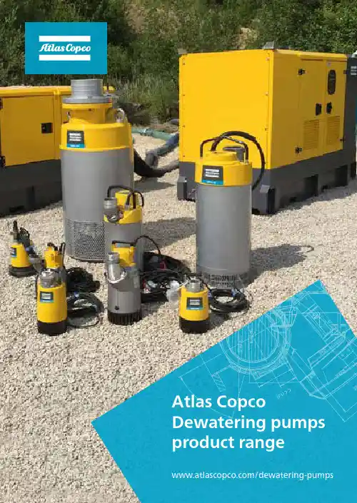
1Atlas Copco Dewatering pumps product rangeS u b m e r s i b l e p u m p s S u r f a c e p u m p sT e r m i n o l o g y A c c e s s o r i e s P a r t s a n d S e r v i c e Othe r I nf o r m a t i o n Index Surface pumps• Dry prime pumps (PAS range)• Wet prime pumps (VAR range)• Wellpoint centrifugal pumps (WEL range)Submersible pumps• Drainage pumps (WEDA D range)• Sludge pumps (WEDA S range)• Slurry pumps (WEDA L range)Terminology• Self primingAccessoriesParts and Service• Service packs• Pump parts• Seal kits, Instant Service pack, Wear part kit and Gasket kit,• Fluids and Lubricants• FleetLinkOther information• Friction losses• Utilities table• Hydraulic characteristicsAtlas CopcoDewatering pumps product rangeDry prime pumps (PAS range)Dewatering | Sewage bypass | Ballasting5S u b m e r s i b l e p u m p s S u r f a c e p u m pT e r m i n o l o g yAc c es s o r i e s P a r t s a n d S e r v i c e O t h e r I n f o r m a t i o n Wellpoint pumps (WEL range)Dewatering to build. Construction | Pipeline on shorePolluted soil remediation | TunnelingWet prime pumps (VAR range)Groundlevel process before excavation for footingsDry prime pumpsPAS range68The PAS range of fully automatic self-priming centrifugal pumps are considered the ideal solution for transporting or raising water with abrasive solids in suspension. They are used across multiple industries including construction and mine site dewatering, floodwater, stream diversions, sewage bypass and municipal64128PAS Performance curveAtlas Copco Dewatering pumps product rangePerformance Curves accor. to UNI 9906 Features :Atlas Copco Dewatering pumps product rangeS u b m e r s i b l e p u m p s S u r f a c e p u m p sT e r m i n o l o g y A c c e s s o r i e sP a r t s a n d S e r v i c ee r I nf o r m a t i o nmaintenance.• High capacity diaphragm pump.• Mechanical seal oil bath.• PW 750 controller• Stackable (canopy version)S u b m e r s i b l e p u m p s S u r f a c e p u m p sT e r m i n o l o g y A c c e s s o r i e sP a r t s a n d S e r v i c ee r I nf o r m a t i o nmaintenance.• High capacity diaphragm pump.• Mechanical seal oil bath.• PW 750 controller.• Stackable (canopy version) .S u b m e r s i b l e p u m p s S u r f a c e p u m p sT e r m i n o l o g y A c c e s s o r i e sP a r t s a n d S e r v i c ee r I nf o r m a t i o n• High capacity diaphragm pump.• Easy serviceability.• Mechanical seal oil bath • PW 750 controllerS u b m e r s i b l e p u m p s S u r f a c e p u m p sT e r m i n o l o g y A c c e s s o r i e sP a r t s a n d S e r v i c ee r I nf o r m a t i o n• Hinge kit for pump maintenance.• High capacity diaphragm pump.• Mechanical seal oil bath.• PW 250 controller.• Stackable.S u b m e r s i b l e p u m p s S u r f a c e p u m p sT e r m i n o l o g y A c c e s s o r i e sP a r t s a n d S e r v i c ee r I nf o r m a t i o n• Hinge kit for pump maintenance.• High capacity diaphragm pump.• Mechanical seal oil bath.• PW 250 controller.• Stackable.S u b m e r s i b l e p u m p s S u r f a c e p u m p sT e r m i n o l o g y A c c e s s o r i e sP a r t s a n d S e r v i c ee r I nf o r m a t i o n• Hinge kit for pump maintenance.• High capacity diaphragm pump.• Mechanical seal oil bath.• PW 250 controller.• Stackable.S u b m e r s i b l e p u m p s S u r f a c e p u m p sT e r m i n o l o g y A c c e s s o r i e sP a r t s a n d S e r v i c ee r I nf o r m a t i o n• Hinge kit for pump maintenance.• High capacity diaphragm pump.• Mechanical seal oil bath.• PW 500 controller.• Stackable.S u b m e r s i b l e p u m p s S u r f a c e p u m p sT e r m i n o l o g y A c c e s s o r i e sP a r t s a n d S e r v i c ee r I nf o r m a t i o n• High capacity vacuum pump.• Mechanical seal oil bath.• PW 750 controller.• Stackable.S u b m e r s i b l e p u m p s S u r f a c e p u m p sT e r m i n o l o g y A c c e s s o r i e sP a r t s a n d S e r v i c ee r I nf o r m a t i o nThe VAR range consists on centrifugal pumps, where the key is to have a simplesystem for first prime. The machine can, with a first water fill up, quickly evacuate the air from the suction and allow to flow the fluid with solid handlings in suspension. The equipment suits perfectly in medium construction application,bentonite pumping and portable emergency floods control.Great for construction, general dewatering, drainage and emergency applications.These self-priming centrifugal pumps are for applications where the main challenge is the difficulty to start the unit in tough conditions and difficult accessible areas.SOLIDS76 mmUP TOHANDLINGFLUSHINGmin1MAX. FLOWUP TO1400m /h24 OF CONTINUOUSOPERATIONHOURSS u b m e r s i b l e p u m p s S u r f a c e p u m p sT e r m i n o l o g y A c c e s s o r i e s P a r t s a n d S e r v i c ee r I nf o r m a t i o nH• Light weight and portable.• Wet prime system.• Easy clean up.S u b m e r s i b l e p u m p s S u r f a c e p u T e r m i n o l o g y A c c e s s o r i e sP a r t s a n d S e r v i c ee r I nf o r m a t i o n• Light weight and portable.• Wet prime system.• Easy clean up.S u b m e r s i b l e p u m p s S u r f a c e p u T e r m i n o l o g y A c c e s s o r i e sP a r t s a n d S e r v i c ee r I nf o r m a t i o nPerformance Curves accor. to UNI 9906 Features :• Light weight and portable.S u b m e r s i b l e p u m p s S u r f a c e p u T e r m i n o l o g y A c c e s s o r i e sP a r t s a n d S e r v i c ee r I nf o r m a t i o nPerformance Curves accor. to UNI 9906 Features :0200S u b m e r s i b l e p u m p s S u r f a c e p u T e r m i n o l o g y A c c e s s o r i e sP a r t s a n d S e r v i c ee r I nf o r m a t i o nPerformance Curves accor. to UNI 9906 Features :S u b m e r s i b l e p u m p s S u r f a c e p u T e r m i n o l o g y A c c e s s o r i e sP a r t s a n d S e r v i c ee r I nf o r m a t i o nPerformance Curves accor. to UNI 9906S u b m e r s i b l e p u m p s S u r f a c e p u m p sT e r m i n o l o g y A c c e s s o r i e sP a r t s a n d S e r v i c ee r I nf o r m a t i o nPerformance Curves accor. to UNI 9906 Features :S u b m e r s i b l e p u m p s S u r f a c e p u m p sT e r m i n o l o g y A c c e s s o r i e sP a r t s a n d S e r v i c ee r I nf o r m a t i o nPerformance Curves accor. to UNI 9906S u b m e r s i b l e p u m p s S u r f a c e p u m p sT e r m i n o l o g y A c c e s s o r i e sP a r t s a n d S e r v i c ee r I nf o r m a t i o nPerformance Curves accor. to UNI 9906S u b m e r s i b l e p u m p s S u r f a c e p u m p sT e r m i n o l o g y A c c e s s o r i e sP a r t s a n d S e r v i c ee r I nf o r m a t i o nQ[l/min] 020*******S u b m e r s i b l e p u m p s S u r f a c e p u m p sT e r m i n o l o g y A c c e s s o r i e sP a r t s a n d S e r v i c ee r I nf o r m a t i o nQ[l/min] 04008001200。
艾默生变频skd34000说明艾默生变频SKD34000说明一、产品介绍•艾默生变频SKD34000是一款高性能的变频设备。
•它采用先进的控制技术,具备精确的速度调节功能。
•艾默生变频SKD34000适用于各种工业领域,能够满足不同的应用需求。
二、产品特点•高效节能:艾默生变频SKD34000能够根据负载自动调整输出功率,实现节能效果。
•稳定可靠:采用先进的电源控制技术,艾默生变频SKD34000具有良好的稳定性和可靠性。
•多功能控制:艾默生变频SKD34000支持多种控制模式,可以根据实际需求进行调节。
•操作简便:通过直观的界面和简化的操作,用户可以轻松地使用艾默生变频SKD34000。
三、应用领域艾默生变频SKD34000广泛应用于以下领域: 1. 制造业:在各类生产线上,可以实现对设备运行速度的精确控制。
2. 建筑行业:用于大型空调、电梯和水泵等设备的能耗调节。
3. 矿山工业:适用于矿山设备的启停控制和负载调节。
4. 冶金行业:用于调节冶金设备的转速和负载。
四、安装和维护1.安装:请根据产品说明书进行正确安装,并确保电源接地可靠。
2.维护:定期检查设备的运行状态和零部件的磨损情况,及时进行维护保养。
3.注意事项:在使用过程中请遵守相关安全规范,确保人身安全和设备安全。
五、联系方式如果您对艾默生变频SKD34000有任何疑问或需求,请联系我们的客服团队:电话:XXX-XXXXXXX,邮箱:。
以上是对艾默生变频SKD34000的简要说明,希望对您有所帮助。
如果您需要更多详细信息,请查阅相关资料或与我们联系。
谢谢!六、技术参数以下是艾默生变频SKD34000的一些重要技术参数: - 输入电压范围:XXXV-XXXV - 额定输入电流:XXA - 输出电压范围:XXXV-XXXV- 频率范围:XXHz-XXHz - 额定输出功率:XXkW - 控制方式:XXX控制 - 保护功能:过载保护、短路保护、过温保护等七、优势与竞争力艾默生变频SKD34000相比于同类产品具有以下优势: 1. 高性能:艾默生变频SKD34000采用先进的控制技术,具备更强的稳定性和输出精度。
0.75kw威乐变频增压泵说明书摘要:1.威乐变频增压泵概述2.威乐变频增压泵的主要特点3.威乐变频增压泵的安装与使用4.威乐变频增压泵的维护与保养5.安全注意事项正文:一、威乐变频增压泵概述威乐变频增压泵是一款具有先进技术的水泵,通过变频技术实现水压的自动调节,以适应不同的用水需求。
该泵适用于住宅、商业建筑、灌溉系统等多种场合,为用户提供高效、节能、安全的供水解决方案。
二、威乐变频增压泵的主要特点1.节能:采用变频技术,根据用水需求自动调节水压,减少能源浪费。
2.高效:优化的水力结构设计,提高水泵效率,降低运行噪音。
3.智能化:内置智能控制系统,可实现自动启停、自动调节水压等功能。
4.安全:具有过载、过热、缺水等保护功能,确保水泵安全稳定运行。
5.耐用:选用优质材料制造,提高了水泵的耐磨性和使用寿命。
三、威乐变频增压泵的安装与使用1.安装前,请确保水泵与电源、水源的连接正确。
2.选择合适的安装位置,确保水泵不受污水、腐蚀、潮湿等因素影响。
3.根据需要连接出水管道,并确保管道连接处密封良好。
4.接通电源,开启水泵,检查水泵运行是否正常。
5.使用过程中,请注意观察水泵的运行状态,如有异常,请及时关闭电源并联系专业人员处理。
四、威乐变频增压泵的维护与保养1.定期检查水泵的运行状态,如有异常,及时进行处理。
2.每隔一定时间,对水泵进行清洁和维护,以延长使用寿命。
3.保持水泵周围环境的清洁,避免污水、腐蚀、潮湿等因素对水泵的影响。
4.长期不使用水泵时,请将电源关闭,并对水泵进行防潮、防锈处理。
五、安全注意事项1.使用前,请仔细阅读说明书,了解水泵的性能参数、安装方法、使用注意事项等内容。
2.非专业人员请勿拆卸、维修水泵,以免造成安全事故。
3.使用过程中,请确保水泵与电源、水源的连接良好,避免触电事故。
威司顿全自动智能冷热水自吸泵说明书【产品概述】威司顿全自动智能冷热水自吸泵是一款高效、可靠、智能的水泵设备。
它具有自吸功能,并可根据需要供应冷热水,适用于各类住宅、商业和工业场所。
【产品特点】1. 全自动功能:威司顿冷热水自吸泵具有智能控制系统,能够自动启停和调节水温,节省能源并提供便利。
2. 高效节能:采用先进的技术和设计,威司顿冷热水自吸泵能够提供高效的水泵性能,同时节省能源消耗。
3. 自吸功能:根据需要,该泵可以自动吸水,减少人工操作,并提供连续的水流供应。
4. 冷热水供应:该泵可根据用户需求自动调节水温,提供冷水或热水供应,满足不同场所和季节的需求。
5. 静音设计:专业的噪音控制技术使得该泵的运作非常安静,不会产生噪音干扰。
【使用方法】1. 安装:将威司顿冷热水自吸泵正确连接到水源和用水设备,确保连接紧固,并注意管道的防漏处理。
2. 开关控制:威司顿冷热水自吸泵配备了智能控制面板,通过面板上的开关按钮可以打开或关闭水泵。
3. 水温调节:在开启水泵后,通过设置控制面板上的水温按钮,调节所需水温,等待泵将水温调节至预设温度。
4. 自吸操作:威司顿冷热水自吸泵具有自动吸水功能,只需打开开关即可进行自吸操作,无需人工干预。
5. 维护保养:定期检查水泵的连接和密封性能,保持水泵清洁,以确保正常的运行和长寿命。
【注意事项】1. 在安装和使用过程中,请务必按照说明书指导进行操作,确保安全使用。
2. 在进行维护和保养时,请确保断开电源,并注意避免触电和烫伤等危险。
3. 若在使用过程中发现异常情况,如噪音、泄露或其他问题,请立即停止使用并与售后服务联系。
威司顿全自动智能冷热水自吸泵是一款高性能、节能环保的水泵设备,它的智能控制和自吸功能使得其在各类住宅和商业场所广泛使用。
通过合理使用和维护,可以确保该泵的正常运行和长寿命。
我们的售后服务团队将全程为您提供支持和解答任何问题,以确保您的满意度和安全使用。

阿姆斯壮泵工作原理-回复阿姆斯壮泵是一种常见的离心泵,广泛应用于水处理、给排水系统、化工工艺等领域。
它的工作原理基于离心力和功率传递的原理。
在本文中,我将一步一步地介绍阿姆斯壮泵的工作原理。
第一步:离心力的作用原理离心力是阿姆斯壮泵工作的基础。
当泵的转子旋转时,液体会被吸入并填充到泵的进口侧。
接着,当叶轮开始旋转时,液体会受到离心力的作用,被迫沿着叶轮的外缘向外推出。
这个过程类似于在旋转的水平轴上旋转物体,物体会受到离心力的推动而远离轴心。
第二步:泵的结构组成阿姆斯壮泵由一个叶轮、一个轴和一个壳体组成。
叶轮是泵的核心部件,它由数个叶片组成,可以将液体送出。
轴将叶轮与电机连接在一起,使其能够旋转。
壳体是泵的外部结构,用于固定和保护内部部件。
第三步:泵的工作过程1. 吸入过程:当泵启动时,叶轮开始旋转,液体被吸入泵壳的进口侧。
这个过程涉及泵的进口和进口管道。
液体通过进口管道流入泵壳,然后进入叶轮。
2. 离心推出过程:当液体进入叶轮后,离心力开始作用。
叶轮旋转时,液体被推向叶轮的外缘,并在离心力的作用下远离泵的轴心。
这个过程涉及液体在泵壳内的流动,并且液体的压力会随着离心力的增加而增加。
3. 出口过程:当液体被完全推出叶轮后,它会进入泵壳的出口侧,并通过出口管道流出。
液体的流出过程涉及泵的出口和出口管道。
第四步:功率传递原理阿姆斯壮泵的工作不仅依赖于离心力,还涉及功率传递。
电机通过轴将旋转力传递给叶轮,使其旋转。
电机为泵提供所需的能量,以推动液体。
第五步:控制和监测系统除了上述工作原理,阿姆斯壮泵还通常配备了控制和监测系统,以确保其正常运行。
这些系统可以包括开关、传感器和自动控制器等。
开关用于启动和停止泵,传感器用于检测泵的工作状态,自动控制器用于根据需求调整泵的工作参数。
总结:阿姆斯壮泵的工作原理基于离心力和功率传递的原理。
通过叶轮的旋转和离心力的作用,液体被迫从进口侧吸入,然后被推入泵壳的出口侧。
飞羽永磁变频智能泵fy168使用说明飞羽永磁变频智能泵FY168是一款高效、节能的水泵设备。
下面将为您详细介绍其使用说明。
一、产品概述飞羽永磁变频智能泵FY168是一种采用永磁同步电机和变频控制器相结合的水泵设备。
它具有高效节能、智能控制、稳定可靠等特点,适用于家庭、农田灌溉、工业生产等场景。
二、安装与调试1. 安装:将FY168泵放置在水源附近,确保水源充足,然后将进水管连接到水源,出水管连接到用水设备。
2. 电源接入:将FY168泵的电源线插入电源插座,并确保电源正常。
3. 开机前准备:在使用之前,需要检查泵体是否密封,管道是否连接牢固,确保安全可靠。
4. 开机运行:按下开关按钮,泵将开始运行。
可以通过变频控制器调节泵的运行速度,以满足不同场景的需求。
三、操作说明1. 开关控制:FY168泵的开关按钮位于泵体上方,按下开关即可启动或停止泵的运行。
2. 变频调节:FY168泵配备了智能的变频控制器,可以根据需要调节泵的运行速度。
通过旋转变频控制器上的旋钮,可以实现泵的调速,以适应不同的用水需求。
3. 故障保护:FY168泵具有多种故障保护功能,如过载保护、过热保护等。
当泵出现异常情况时,变频控制器会自动停止泵的运行,并显示故障代码。
此时需要检查并解决故障后,方可重新启动泵。
四、注意事项1. 使用前请确保电源接入正常,并检查电源线是否完好。
2. 安装时请确保泵体密封,管道连接牢固。
3. 在使用过程中,如遇到异常情况,请立即停止使用,并联系售后服务人员进行检修。
4. 长时间不使用时,请切断电源,并将泵体放置在干燥通风的地方。
5. 请勿将FY168泵用于非指定场景,以免造成设备损坏或人身伤害。
总结:飞羽永磁变频智能泵FY168是一款高效节能的水泵设备,具有智能控制、稳定可靠等特点。
使用时需注意安装和调试步骤,正确操作开关和变频调节器。
在使用过程中,要注意故障保护和注意事项,确保设备正常运行和用户安全。
Horizontal Base Mounted Pumps4030f Armstrong, manufacturer of pumps since 1934.f Base mounted pump designs continuously updated.f Traditional features combined with cutting edge concepts.f Traditional FeaturesfArmstrong Pumps - Hallmark of Qualityf Back pull out design.f One piece baseplate.f Base supported radially-split casing.f Flexible coupling with guard.f Drain and gauge connections.f Cast iron housing, bronze-fitted construction.f All iron and ductile iron construction available.f Designed, manufactured and inspected toexacting standards.f Current Design Conceptsf ANSI style centerline discharge casing.f large flow range.f ANSI flanged casing.f Pre-lubricated and sealed ball bearings.f Confined casing gasket.f Mechanical seal with O-ring mounted silicone carbide seat.f Stainless steel shaft sleeve.f Dynamically balanced impellers.f OSHA coupling guard.f Baseplate designed to ANSI/HI 1.3.5 rigidity standardsfor freestanding base.The best base mounted pump design in today’s HVAC industry.f Pressure/Temperature Chart Series 4030ACast Iron - 125 psig Standard seal.BDuctile Iron - 250 psig flanges Carbide seal.Notes:f Hydrostatic test pressure at ambient temperature is 150% maximum working pressure.f All values are based on clear, clean water. Values may change with other liquids.Base Mounted Centrifugal PumpsDrilled and tapped connections for gauges and drain.Radially split casing provides pull out design that allows removal of bearing assembly and impeller without disturbing pipe connections.Gasket, non-asbestos,confined asrecommended by ANSI.OSHA coupling guard provided on all pumping units.Bearing assemblytwo anti-friction bearings,permanently lubricated,carry design loads with minimum maintenance.Single spring mechanical seal with O-ring mounted silicone carbide seat providesleak-proof operation throughout pump range.Base supported casing eliminates need to support casing when bearing assembly is removed.Stainless steel shaft sleeve.Dynamically balancedcast bronze or iron impeller.A heavy fabricated steel baseplate, rigidly constructed to ANSI/HI 1.3.5standards, provides for proper alignment of pump and motor.For Armstrong locations worldwide, please visit S . A . A r m s t r o n g L i m i t e d 23 Bertrand Avenue T oronto, Ontario Canada, M1L 2P3T : (416) 755-2291F (Main): (416) 759-9101A r m s t r o n g P u m p s I n c .93 East AvenueNorth T onawanda, New Y ork U.S.A., 14120-6594T : (716) 693-8813F : (716) 693-8970A r m s t r o n g H o l d e n B r o o k e P u l l e n Wenlock Way ManchesterUnited Kingdom, M12 5JL T : +44 (0) 161 223 2223F : +44 (0) 161 220 9660© S.A. Armstrong Limited 2007Furnish and install, as indicated on the plans and specifications, Armstrong Series 4030 base mounted centrifugal pumps.The pump shall be single, end suction type with radially split, top center-line discharge, self-venting casing. The casing-to-cover gasket shall be confined on the atmospheric side to prevent blow-out possibility.Pump construction shall be cast iron, bronze fitted (all iron, all bronze, ductile iron) and shall be fitted with a long-life, product lubricated, drip-tight mechanical seal, with O-ring silicone carbide seat retainer, designed for the specified maximum temperature and pressure.The shaft shall be fitted with a Stainless Steel shaft sleeve and be supported by two heavy duty ball bearings. The design shall allow Back Pull Out servicing, enabling the complete rotating assembly to be removed without disturbing the casing piping connections.The pump shall be mounted on a rigid baseplate, designed to ANSI/HI 1.3.5 rigidity standards, for grouting or freestanding, and connected by flexible coupling, with OSHA guard, to a ____ hp, ____ Hz, ___ phase, ____ Volts, _____ rpm, _____ enclosure squirrel cage, induction type motor of Federally approved (premium, ____%) efficiency level and suitable for across-the-line (wye-delta, part wind) starting.The housing shall be hydrostatically tested to 150% maximum working pressure.The unit shall be suitable for the conditions shown on the pump schedule.f TYPICAL SPECIFICATIONNeed to reduce space requirements and installation costs?f Vertical In-LineArmstrong SG Suction Guide with StrainerArmstrong FTV-S Flo-Trex Combination ValveArmstrong SG Suction Guide with StrainerArmstrong FTV-A Flo-Trex Combination ValveArmstrong SG Suction Guide with StrainerArmstrong Base mounted pump with Suction Guide and Flo-Trex valve eliminates cost and dualArm Vertical In-Line incorporates two。
昂东水泵说明书昂东水泵是一种高效、可靠的水泵装置,可广泛应用于农田灌溉、工业用水、城市给排水等领域。
本说明书将为您介绍昂东水泵的基本结构、工作原理和操作方法,以及使用时需要注意的事项。
一、基本结构:昂东水泵主要包括泵体、叶轮、轴承、传动装置和进出水口等部分。
泵体是水泵的主体部分,一般采用铸铁或不锈钢材料制成,具有良好的耐腐蚀性能。
叶轮是泵体内旋转的关键部件,通常由合金材料制成,能够有效提升水流速度。
轴承用于支撑叶轮的旋转,采用优质轴承材料,具有较高的承载能力。
传动装置一般采用电机和联轴器,将电机的动力传递给泵体。
进出水口用于泵水进出,其位置和尺寸需要根据具体需求进行调整。
二、工作原理:昂东水泵采用离心力的原理,通过叶轮的旋转将水抽入泵体,并将水流向出水口。
当电机启动后,通过传动装置将动力传递给泵体,使泵体内部的叶轮高速旋转。
由于叶轮的旋转,泵体内部的压力降低,形成负压,水被抽入泵体,然后被迅速排出。
通过连续的抽水和排水过程,实现了水的循环流动。
三、操作方法:1.连接电源:首先将泵体正确地连接到电源上,确保电源线路没有短路或漏电等问题,以免影响正常运行。
2.启动电机:检查电机和传动装置是否正常,然后按照电机启动程序启动电机。
在启动过程中,注意观察电流、电压等指标,确保其在正常范围内。
3.设置工作参数:根据需求调整水泵的进出水口位置和尺寸,以及转速和功率等参数,以满足具体使用场景的需求。
4.正常运行:当电机启动后,水泵应开始抽水并将水流向出水口。
在运行过程中,及时观察泵体的运行状态,确保没有异常振动、漏水等问题。
同时,注意监测电机的温度,防止过热现象发生。
四、注意事项:1.请勿在没有水的情况下启动电机,以免损坏水泵。
2.在使用水泵之前,请检查进水口是否存在堵塞物,确保水泵能够正常抽水。
3.在长时间使用水泵后,应进行定期检查,清洁泵体内部的沉淀物和污垢,并检查轴承和传动装置的磨损程度。
4.请勿随意拆卸或修改水泵的零部件,以免影响其正常运行。
上海臣源数显微电脑全自动智能泵说明书引言:数显微电脑全自动智能泵是一种集数显、微电脑、全自动及智能控制于一体的高科技产品。
本说明书将详细介绍该泵的特点、使用方法以及维护保养等方面的内容,帮助用户更好地了解和使用该产品。
一、产品特点1.1 数显功能该泵配备了数显功能,能够直观地显示当前的工作状态、流量、压力等参数,方便用户随时监控和调整。
1.2 微电脑控制采用先进的微电脑控制技术,可以根据用户设定的参数进行智能化控制,实现自动运行和保护。
1.3 全自动运行该泵具备全自动运行功能,只需要设置好运行参数,泵就可以自动启停,大大减轻了用户的操作负担。
1.4 智能保护泵具备多种保护功能,如短路保护、过载保护、过热保护等,能够有效避免因意外故障引起的损坏。
1.5 高效节能泵采用先进的设计和制造工艺,具有高效节能的特点,能够在保证运行效果的同时,最大限度地降低能耗。
二、使用方法2.1 安装(1)选择合适的安装位置,确保泵能够稳定地工作,并且方便进行维护保养。
(2)根据安装位置和需要,连接好进出水管道,并确保连接处密封可靠。
(3)接通电源,确保泵正常工作。
2.2 设置参数(1)按下设置键进入参数设置模式。
(2)根据实际需求,设置好相关参数,如运行时间、流量、压力等。
(3)设置完成后,按下确认键保存设置。
2.3 启动泵(1)按下启动键,泵将按照设定的参数开始工作。
(2)泵开始运行后,可以通过数显功能查看当前的工作状态和相关参数。
2.4 停止泵(1)按下停止键,泵将停止工作。
(2)在停止泵之前,应确保泵的运行状态正常,并且关闭进出水阀门。
三、维护保养3.1 定期检查定期检查泵的电源线、进出水管道等连接处是否松动或漏水,如有问题及时处理。
3.2 清洁维护定期清洁泵的外壳和进出水口,防止灰尘和杂质积累影响泵的正常工作。
3.3 润滑保养根据使用情况,定期给泵的轴承和密封件添加润滑油,以保证泵的顺畅运转和密封性能。
四、注意事项4.1 在安装和使用过程中,应严格按照本说明书的要求进行操作,避免因错误操作导致故障或事故。