泰科电子_照明产品目录和应用指南
- 格式:pdf
- 大小:4.87 MB
- 文档页数:60

照明产品目录照明连接方案速查手册1-11773931-1 (1)模组化可退线POKE-IN插入式连接器1-1773872-8 (8)POKE-IN插入式纤薄导线连接器1-1773909-3 (10)SLIM线到板连接器 POKE-IN 1-1773870-4 (12)模组化免螺丝端子台1-1773872-7 (14)COOLSPLICE系列连接器1-1773891-8 (16)COOLSPLICE系列连接器-大线径1-1773884-7 (18)微型SLIMSEAL防水连接器系列1-1773896-3 (20)SLIMSEAL圆形防水连接器系列1-1773883-9 (23)推紧式导线连接器1-1773884-2 (25)旋转接头导线连接器1-1773884-6 (27)2P免压接线到线连接器1-1773870-5 (29)2位LIGHT-N-LOK模组化带锁扣连接器1-1773886-4 (31)3位LIGHT-N-LOK模组化带锁扣连接器1-1773886-5 (33)调光光控器底座和上盖1-1773879-1 (35)LUMAWISE ENDURANCE S模块1-1773915-3 (37)ANSI_C136 41_可旋转调光插座1-1773278-9 (41)LUMAWISE LED底座8-1773700-9 (43)LUMAWISE LED免焊接底座1-1773869-1 (49)LUMAWISE Z32 LED免焊接底座1-1773700-1 (51)LUMAWISE Z35 LED免焊接底座1-1773882-6 (53)LUMAWISE调光光控器底座、套筒和上盖1-1773879-1 (55)接地线夹组件1-1773919-9 (57)NECTOR M密封防水PCB面板安装连接器1-1773923-3 (61)照明连接方案速查手册街道照明户外照明TE Connectivity特色产品照明子系统解决方案•天线•屏蔽罩(BLS)•EMI 滤波器•继电器和开关•精密电阻器•太阳能接线盒•电动汽车充电线束请访问我们的网站:LUMAWISE 调光插座、底座和上盖型号2213362-22213627-22213730-12213748-1产品信息1-1773728-91-1773872-81-1773879-1LUMAWISE Endurance S模块型号2213858-12213837-12213795-1产品信息1-1773915-3SLIMSEAL 圆形连接器系列型号9-2834004-19-2834005-1产品信息1-1773883-9NECTOR M电缆组件型号2829460-12829488-1产品信息5-1773465-6COOLSPLICE 系列连接器型号2213800-22213800-42213600-12213600-22213600-3适用线径18 AWG 0.75mm 220-22 AWG 0.52-0.34mm 212/14-14/16 AWG 4.0/2.5-2.5/1.5mm 212/14-16/18 AWG 4.0/2.5-1.5/0.75mm 214/16-16/18 AWG 2.5/1.5-1.5/0.75mm 2产品信息1-1773891-81-1773884-7模组化可释放的插入式连接器型号2834006-11-2834006-05-2834006-3适用线径18-22 AWG (Solid & Stranded)产品信息1-1773872-8型号1-2834074-21-2834075-22-2834074-32-2834075-3适用线径18-22 AWG Max2.0mm 绝缘外径产品信息1-1773896-3SLIMSEAL 微型IP67防水线到线连接器系列型号2834048-22834049-22834054-12834055-1适用线径16-22 AWG (Solid & Stranded)产品信息1-1773886-41-1773886-5LIGHT-N-LOK 带锁扣的模组化连接器灯具电源和控制室内照明TE Connectivity照明子系统Array解决方案•天线•屏蔽罩(BLS)•EMI 滤波器•继电器和开关•精密电阻器•传感器•端子和连接头请访问我们的网站:户外照明——街道照明模组化 可释放的插入式连接器型号2834006-11-2834006-05-2834006-3适用线径18-22 AWG (Solid & Stranded)产品信息1-1773872-8型号1-2834074-21-2834075-22-2834074-32-2834075-3适用线径18-22 AWG Max2.0mm 绝缘外径产品信息1-1773896-3SLIMSEAL 微型IP67防水线到线连接器系列LUMAWISE LED底座型号2213678-32213407-12213407-22213480-1产品信息8-1773700-9型号2834048-22834049-22834054-12834055-1适用线径16-22 AWG (Solid & Stranded)产品信息1-1773886-41-1773886-5LIGHT-N-LOK 带锁扣的模组化连接器免剥线压入式连接器型号2106431-22106003-2适用线径贯穿式 18AWG封闭式 18AWG产品信息5-1773455-12P 免压接线到线连接器型号2271180-12271183-1适用线径18-22AWG18-22AWG产品信息1-1773863-8紧凑型线到板Poke-In 连接器型号2834172-32834171-32834167-32834012-32834010-3适用线径与2834167-3互配20-24AWG 18-22AWG16-20AWG20-24AWG产品信息1-1773909-31-1773869-6型号2299514-12299515-12299518-1适用线径22-12AWG22-12AWG 22-12AWG产品信息1-1773884-2推紧式导线连接器TE Connectivity 和 TE connectivity (logo) 均为商标。
TE电路保护产品的创新历史可以追溯到1980 年,当年TE 率先在电路保护应用中将PPTC器件作为可变电阻使用。
从手机电池到汽车方向盘,TE电路保护产品已在日常生活中无处不在,始终致力於为更安全的生活环境并提高电子产品的可靠性。
时至今日,数以亿计的TE电路保护产品已在众多电子产品领域中被广泛运用:计算机,电池,便携式电子产品,电子消费品,汽车电子,工业以及电信业市场等。
全球范围内的TE电路保护产品的各家机构均已通过IS09000 / TSl6949 标准认证。
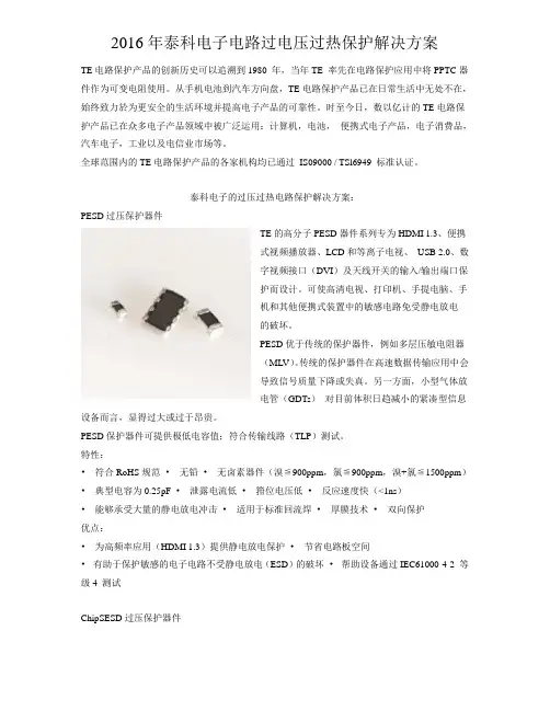
泰科电子的过压过热电路保护解决方案:PESD过压保护器件TE的高分子PESD器件系列专为HDMI 1.3、便携式视频播放器、LCD和等离子电视、USB 2.0、数字视频接口(DVI)及天线开关的输入/输出端口保护而设计。
可使高清电视、打印机、手提电脑、手机和其他便携式装置中的敏感电路免受静电放电的破坏。
PESD优于传统的保护器件,例如多层压敏电阻器(MLV)。
传统的保护器件在高速数据传输应用中会导致信号质量下降或失真。
另一方面,小型气体放电管(GDTs)对目前体积日趋减小的紧凑型信息设备而言,显得过大或过于昂贵。
PESD保护器件可提供极低电容值;符合传输线路(TLP)测试。
特性:•符合RoHS规范•无铅•无卤素器件(溴≦900ppm,氯≦900ppm,溴+氯≦1500ppm)•典型电容为0.25pF •泄露电流低•箝位电压低•反应速度快(<1ns)•能够承受大量的静电放电冲击•适用于标准回流焊•厚膜技术•双向保护优点:•为高频率应用(HDMI 1.3)提供静电放电保护•节省电路板空间•有助于保护敏感的电子电路不受静电放电(ESD)的破坏•帮助设备通过IEC61000-4-2 等级4 测试ChipSESD过压保护器件TE Circuit Protection的ChipSESD硅静电放电保护器件系列采用了EIA-0201 和EIA-0402尺寸的矩形SMT无源器件封装,有助於保护电子电路免受静电放电的损坏。
SUNSTAR 商斯达微波光电公司 射频、微波、光纤、光电、通讯产品目 录更多产品请看本公司产品专用销售网站:欢迎来电查询购买商斯达产品或索取免费详细资料、设计指南和光盘;产品繁多,未能尽录,欢迎来电查询。
商斯达射频微波光电产品网:/商斯达中国传感器科技信息网:/商斯达工控安防网:/商斯达电子元器件网:/商斯达军工产品网:hrrp:///商斯达消费电子产品网:///商斯达实业研制科技产品网:/// 射频微波光电元器件销售热线:地址:深圳市福田区福华路福庆街鸿图大厦1602室电话:0755-******** 83397033 83398585 82884100MSN:邮编:518033 E-mail:QQ: 195847376深圳赛格展销部:深圳华强北路赛格电子市场2583号 电话:0755-******** 25059422 技术支持: 0755-******** 135********北京分公司:北京海淀区知春路132号中发电子大厦3097号TEL:82615020 FAX:上海分公司:上海市北京东路668号上海賽格电子市场D125号TEL:56703037 FAX:西安分公司:西安高新开发区20所(中国电子科技集团导航技术研究所)西安劳动南路88号电子商城二楼D23号TEL:Aavid ThermalloyABRACON CorporationAEPAeroflex INMETAeroflex KDI Resistor ProductsAmerican Tech Ceramics (ATC)AmphenolANADIGICSAnarenAnaren/RF PowerArcotronicsAvago TechnologiesBOMAR Interconnect Products, Inc.Cornell DubilierCrystek CorporationCTS CorporationDynex SemiconductorElectronic Devices, Inc.Emerson Network Power (formerly Johnson Components) Empower RF Systems, Inc.EPCOS F.W. BellFractusfree2moveFreescale Semiconductor, Inc. General ElectricGoreHoneywellHuber+SuhnerHVVIIllinois Capacitor, Inc.Infineon TechnologiesIQD Frequency ProductsJohanson ManufacturingLaird TechnologiesM/A-COM Technology Solutions Maxwell TechnologiesMicrosemiMicrosemi (Santa Clara)Mimix Broadband (formerly Celeritek) Mitsubishi ElectronicsNational ElectronicsNDKNEC Compound Semiconductors NitronexOhmitePacific MonolithicsPCTEL (Maxrad, Inc.)Peregrine Semiconductor PolyPhaser Corporation PowerexRadiallRadiotronixRaltronRES - IngeniumRF IndustriesRichardson Component Solutions Richardson Power Solutions Richardson System Solutions RiedonSDP Components, Inc. SemeLab, PlcSemikron Spectrum Advanced Specialty Products Spectrum MicrowaveST MicroelectronicsSV MicrowaveTeledyne CoaxTeledyne RelaysTensolite CDI/QMIToko AmericaTyco ElectronicsUnited Chemi-con, Inc.United Monolithic Semiconductors (UMS) Valpey FisherVincotechVishayWakefield Thermal SolutionsWanTcomWavecomWestcode Semiconductors, Inc.WJ CommunicationsMTI MilanoPacific MonolithicsMini-Circuits公司是1969年由 Harvey Kaylie先生创立的。
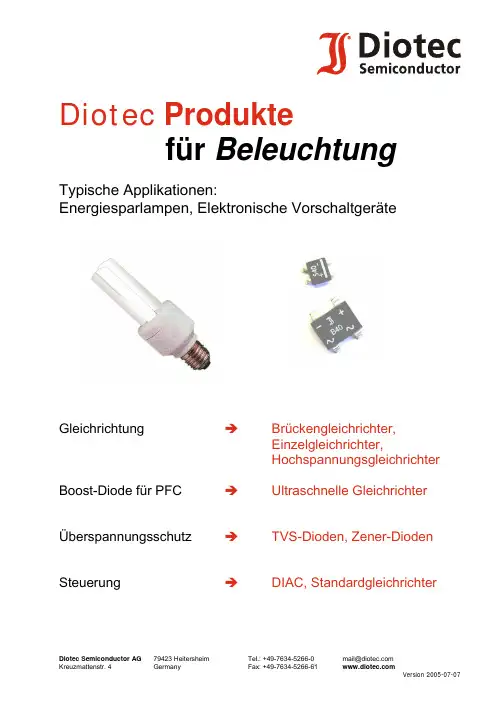
Diotec Produktefür BeleuchtungTypische Applikationen:Energiesparlampen, Elektronische VorschaltgeräteGleichrichtung Î Brückengleichrichter,Einzelgleichrichter, HochspannungsgleichrichterBoost-Diode für PFC Î Ultraschnelle GleichrichterÜberspannungsschutz Î TVS-Dioden, Zener-DiodenSteuerung Î DIAC, StandardgleichrichterEnergiesparlampenÜberspannungsschutz: TVS-Dioden/ZenerdiodenZum Schutz der MOSFET-Gates können entweder Zener- oder TVS Dioden verwendet werden. Dimensionierung der TVS Dioden: siehe Applikationsschrift “Überspannungsschutzdioden“.Typen1TGL34-… , TGL41…, P4SMAJ…, P6SMBJ…, 1.5SMCJ…; (150 bis 1500 W Impuls; bis zu 550 V!) ZMM…,ZMD…, ZMY..., SMZ1..., SZ3C…, Z1SMA, Z2SMB…, Z3SMC…; (0.5 bis 3 W dauernd) Eingangsgleichrichtung: BrückengleichrichterErhältlich als komplettes Bauteil, kann aber auch aus vier Einzeldioden aufgebaut werden (siehe unten). Empfohlene Werte für den Schutzwiderstand R t und den Lastkondensator C L sind im Datenblatt angegeben. R t beinhaltet auch den Serienwiderstand des Eingangskreises, ein zusätzliches Bauteil ist daher oft nicht notwendig.Typen1SMD: MYS40…250, MS40…500,S40…500, B40…500S, B40…380F S(s c h n e l l) Durchsteckmontage: B40…500D, B40…380F D(s c h n e l l), B40…500R (rund)(0.5 bis 2 A)Entladediode: EinzelgleichrichterTypen1GL34 A..M, GL1 A..M, SM4001…7, SM5059…63, SM5400…08, S1 A..M, S2 A..M, S3 A..M;(0.5 bis 3 A, Standard).S c h n e l l e bis Ultraschnelle Versionen ebenfalls erhältlich. Startelement: DIACSMD: BR100-03 LLD(V BO 28..36 V), BR100-031 LLD (30..34 V), BR100-04 LLD (35..45 V)Axial: BR100-03 (V BO 28..36 V), BR100-031 (30..34 V), BR100-04 (35..45 V), DB3, DB41Vorzugstypen sind fettgedruckt; Farben entsprechend dem Diotec Selection Guide. Datenblätter siehe, …Produkte“. Neben den hier gezeigten Bauteilen in SMD-Technik (zur Platz- undGewichtsreduzierung) sind auch äquivalente Typen in axialer Bauform erhältlich.Überspannungsschutz: TVS-Dioden/ZenerdiodenZum Schutz der MOSFET-Gates können entweder Zener- oder TVS Dioden verwendet werden. Dimensionierung der TVS Dioden: siehe Applikationsschrift “Überspannungsschutzdioden“.Typen1SMD:TGL34-… , TGL41…, P4SMAJ…, P6SMBJ…, 1.5SMCJ…; (150 bis 1500 W Impuls; bis zu 550 V!)ZMM…,ZMD…, ZMY..., SMZ1..., SZ3C…, Z1SMA, Z2SMB…, Z3SMC…;(0.5 bis 3 W dauernd)Bedrahtet: B ZW04-…, P4KE…, BZW06-…, P6KE…, 1.5KE… , 5KP…; (400 bis 5000 W Impuls) ZPY…, ZY…, 3EZ…, BZV58C…, 1N53..B; (1.3 bis 5 W dauernd) Eingangsgleichrichtung: BrückengleichrichterErhältlich als komplettes Bauteil, kann aber auch aus vier Einzeldioden aufgebaut werden. Empfohlene Werte für den Schutzwiderstand R t und den Lastkondensator C L sind im Datenblatt angegeben. R t beinhaltet auch den Serienwiderstand des Eingangskreises, ein zusätzliches Bauteil ist daher oft nicht notwendig.Typen1SMD: MYS40…250, S40…500, B40…500S, B40…380F S(s c h n e l l)Durchsteckmontage: B40…500D, B40…380F D(s c h n e l l), B40…500R (rund)(0.5 bis 2 A)1.5 bis 12 A:Single In-line: B..C1500, B..C2300-1500; B..C3200-2200 bis B..C7000-4000; GBS4 A..M, GBU4 A..MA..MbisGBU12Ultraschnelle Dioden für PFC StufeDie Taktfrequenz ist im Normalfall relativ hoch, um daher die Verluste im Schalter zu reduzieren (die stark vom Rückstromverhalten der Diode abhängen!) muss eine ultraschnelle Diode verwendet werden. Am 230 V-Netz sollte ein 600 V Typ eingesetzt werden, bei110 V ist ein 400 V Typ ausreichend. Typen1Bedrahtet: UF4004, UF4005, UF5404, UF5406, UF600J; (1 bis 6 A)SMD: SUF4004, SUF4005, US1J, US1G, US2J, US2G, US3G, US3J; (1 bis 3 A)1Vorzugstypen sind fettgedruckt; Farben entsprechend dem Diotec Selection Guide. Datenblätter siehe, …Produkte“.HochspannungsgleichrichterTypen1SMD:SM513…SM2000 (1A Standard); S A261…S A265(2A F a s t) (1300…2000 V);Leaded:EM513…EM518 (1A Standard); BY255…BY2000 (3A Standard) (1300…2000 V);H V1.5,H V2(500m A,1.5t o2k V F a s t);H V3,H V5(200m A,3t o5k V F a s t)D D300…D D1800(20m A,3k V t o18k V F a s t)1Vorzugstypen sind fettgedruckt; Farben entsprechend dem Diotec Selection Guide. Datenblätter siehe , …Produkte“.。


Frame Type Plug-in UnitsELECTRONICS PROTECTIONSCHROFF PRODUCT CATALOG 04/2021Frame type plug-in units –KitsAccessories for cabinets and wall mounted cases . . 3Climate control . . 4Electronicscases . . . . . . . . . 5Subracks/19" chassis . . . . . 6Front panels,plug-in units . . . . 7Systems . . . . . . . 8Power supplyunits . . . . . . . . . . 9Backplanes . . . . 10Connectors, front panel component system . . . . . . . 11Appendix . . . . . 120480700219" modules are mechanical components that serve to carry one or more circuit boards. The boards housed in a module are thus combined into a larger electronic function unit that is self-contained and testable. Mechanical dimensions conform to IEC 60297-3-101 / IEEE 1101.1/11 standards, i.e. the so-called 19" standard. These function units are integrated into the subrack or case; their dimensions likewise form a component of IEC 60297-3-101 / IEEE 1101.1/11.The dimension obligations of the standard give only little freedom for individual design of frame typeplug-in units. The aim is therefore to make optimum use of what freedoms regarding dimensions it does allow, e.g. •to maximise the internal space of a plug-in unit and thus create maximum space for electronic components, or•to ensure optimal EMC shielding with minimum loss of mounting space to the shielding componentsStandards•IEC 60297-3-101 / IEEE 1101.1/11OVERVIEWMAIN CATALOGCabinets . . . . . . . 1 Wall mountedcases . . . . . . . . . 22 |/SCHROFFFrame type plug-in units –KitsOVERVIEWFRAME-TYPE PLUG-IN UNITS TO HOUSE PRINTED BOARDS•For PCBs in euroboard format•Kits or configuration from single components •Front panels: unshielded or EMC shieldedFRAME-TYPE PLUG-IN UNITS PRO•Kit or configuration from single components in 3 U and 6U, 8 (42)HP •Shielded and unshielded versions •Side panel with/without cooling fins•For one or several PCBs or one or several connectors •Various possibilities for combining the individual components04808008PLUG-IN UNITS PRO WITH HOOD•Kit in 3 U and 6 U, 5...14HP •Shielded and unshielded versions •For one PCB with one connector04808009HF FRAME-TYPE PLUG-IN UNITS•Kit or configuration from single components in 3 U, 7...28 HP •For shielding against high-frequency radiation •Tube with cooling fins, in extruded aluminium •For one or more PCBs, one or more connectors04892005SERVICEPLUSe.g. individual configuration and assembly e.g. modification (special colours)e.g. customised solutions with modified frame-type plug-in units (special sizes)Overview . . . . . . 7.64Introduction:Product features, productcomparison . . . . 7.66Frame type plug-in units PROFrame typeplug-in units PRO, shielded/unshielded . . . . . . 7.68Frame-typeplug-in units PRO with hood,unshielded . . . . . . 7.83HF plug-in unitsKits 3 U . . . . . . . . . . 7.87ServicePLUSconfiguration . . . . 7.88Accessories for plug-in units see page . . ... . . . 7.52/SCHROFF |3Frame type plug-in unitsSCHROFF PRODUCT CATALOG 04/20210480801404808013Rear view: frame type plug-in unit mounted in subrack04808012Board for slot 1 fixes to the side panel; further boards are fixed with guide rails0480801104808016Sliding cover platesThe frame type plug-in units conform to IEC 60297-3-101.They serve to house standardized PCBs and bulky components.Because of the standardized assembly dimensions the frame type plug-in units can be mounted on guide rails, to be pushed into the subrack, in any order and using any plug-in unit.The robust Al extrusion construction is especially suited for heavy components and the rough handling as "Field Replaceable Unit".DetailsTHE NEW GENERATIONThe EMC version of the front panel was improved for frequencies over 1 GHz by using a conductive textile gasket and a robust U-shaped front panelPush-in cover plates for quick fittingHandles to be bolted-on from the front, easy mountingOptimised air flow rate thanks to slender extruded side panels and large perforation areas in the cover plates, a perforation degree of up to 65% is possible3 cover plate versions (solid, perforated, perforated for guide rail mounting)Width of frame-type plug-in units from 8HPTo achieve a higher airflow rate, exceptionally slender guide rails are used to fix the boardsFrom slot 2 guide rails can be positioned in HP grid Easy fixing of the boards in the frame-type plug-in units; only 2x 1screws per board are needed to fix the boards3 rear panel variants (solid, for one DIN connector, for multiple DIN connectors)The flat rear panel enables simple reworking (e.g. punching); the rear panel can be removed without removing the PCBsFor better EMC contacting between rear panel and cover plate and to increase the stability of broad frame-type plug-in units, a rear panel retainer is availableUse of Torx screws for secure machine mountingNote:Frame type plug-in units cannot be combined with guide rails for CompactPCI or VME64x applications (width 4HP)4 |/SCHROFFFrame type plug-in units/SCHROFF |Part number in bold face type: ready for despatch within 2 working days Part number in normal type: ready for despatch within 10 working daysCOMPARISON: FRAME-TYPE PLUG-IN UNITS PRO/FRAME-TYPE PLUG-IN UNITS PRO WITH HOODFrame-type plug-in units PRO with hood (shielded)Frame-type plug-in units PRO0480812504808115Only for one PCBFor one or multiple PCBsModular, at least 6 components(front panel,2side panels, 2cover plates,rear panel)Only 3 components(front panel, left hand side panel, hood with integrated rear panel)Identical front panel and front handle Identical front panel and front handle Identical left hand side panel (Al extrusion)Identical left hand side panel (Al extrusion)Side panel on right hand side (Al extrusion)Hood on right hand side (Al sheet)Separate rear panel Hood includes rear panel Widths from 8HP to 42HPWidths from 5HP to 14HPGuiding in subrack/case with 4 guide rails; left and right side panels Guiding in subrack/case with 2guide rails; left side panel3 rear panel variants (for one DIN connector, for multiple DIN connectors, rear panel without cut-out)1 rear panel variant (for one DIN connector)5SCHROFF PRODUCT CATALOG 04/2021Frame type plug-in units PRO•Extruded side panels with groove to rigth and left, to insert a PCB (board position in accordance with standard in left side panel only)• 2 board depths: 160 mm and 220 mm • 2 cover plate versions•with perforation, for guide rails (5a, airflow rate approx. 60%); please order guide rails separately •Without perforation (5b)• 2 rear panel versions•With cut-out for one connector(3a, in accordance with EN 60603-2, DIN 41612)•With cut-out for multiple connectors(3b,in accordance with EN 60603-2, DIN 41612)DELIVERY COMPRISES (Kit)ORDER INFORMATION•Description of individual components, guide rails, dimension drawings, other combinations cover plates/rear panels etc. see from page 7.72FRAME TYPE PLUG-IN UNITS PRO, 3 U KITS, FRONT PANEL SHIELDED (TEXTILE GASKET)04811007Illustration shows 12 HP width, side panel depth 167 mmItem Qty DescriptionFront panel, U profile anodised, rear conductive, alignment pin 11pressed-in21Handle, grey, PPE, UL 94V-1Rear panel, St, zinc-plated, 1.5mm, with cut-out for one 13a connector, incl. PCB fixing (slot 1)3b3c 12Rear panel, St, zinc-plated, 1.5mm, with cut-out for multiple connectors, incl. PCB fixing (slot 1 and slot 2), incl. 2 guide rails rear panel fastener24Side panel, Al extrusion, colourless passivated,with groove for one PCB5a 2Cover plate, St, zinc-plated, 1.0mm, with perforation 25b Cover plate, St, zinc-plated, 1.0mm, without perforation 61EMC sealing (textile)17Assembly kit6 |/SCHROFFFrame type plug-in units PROPart number in bold face type: ready for despatch within 2 working days Part number in normal type: ready for despatch within 10 working days•Extruded side panels with groove to rigth and left, to insert a PCB (board position in accordance with standard in left side panel only)• 2 board depths: 160 mm and 220 mm • 2 cover plate versions•With perforation, for guide rails (5a, airflow rate approx. 60 %),•please order guide rails separately •Without perforation (5b)• 2 rear panel versions•With cut-out for one connector(3a; in accordance with EN 60603-2, DIN 41612)•With cut-out for multiple connectors(3b;in accordance with EN 60603-2, DIN 41612)• 6 U has cut-outs for connectors at top and bottomDELIVERY COMPRISES (Kit)ORDER INFORMATION•Description of individual components, guide rails, dimension drawings, other combinations cover plates/rear panels etc. see from page 7.72FRAME TYPE PLUG-IN UNITS PRO, 6 U KITS, FRONT PANEL SHIELDED (TEXTILE GASKET)04811008Illustration shows 12 HP width, side panel depth 167 mmItem Qty DescriptionFront panel, U profile anodised, rear conductive, alignment pin 11pressed-in21Handle, grey, PPE, UL 94V-1Rear panel, St, zinc-plated, 1.5mm, with cut-out for one 13a connector, incl. PCB fixing (slot 1)3b3c 12Rear panel, St, zinc-plated, 1.5mm, with cut-out for multiple connectors, incl. PCB fixing (slot 1 and slot 2), incl. 2 guide rails rear panel fastener24Side panel, Al extrusion, colourless passivated,with groove for one PCB5a 2Cover plate, St, zinc-plated, 1.0mm, with perforation 25b Cover plate, St, zinc-plated, 1.0mm, without perforation 61EMC sealing (textile)17Assembly kit/SCHROFF |7SCHROFF PRODUCT CATALOG 04/2021Frame type plug-in units PRO•Extruded side panels with groove to rigth and left, to insert a PCB (board position in accordance with standard in left side panel only)• 2 board depths: 160 mm and 220 mm • 2 cover plate versions•with perforation, for guide rails (5a, airflow approx. 60%);please order guide rails separately •Without perforation (5b)• 2 rear panel versions•With cut-out for one connector(3a, in accordance with EN 60603-2, DIN 41612)•With cut-out for multiple connectors(3b,in accordance with EN 60603-2, DIN 41612)DELIVERY COMPRISES (Kit)ORDER INFORMATION•Description of individual components, guide rails, dimension drawings, other combinations cover plates/rear panels etc. see from page 7.72FRAME-TYPE PLUG-IN UNITS PRO, 3 U KITS, FRONT PANEL UNSHIELDED04811009Illustration shows 12 HP width, side panel depth 167 mmItem Qty DescriptionFront panel, Al, 2.5 mm, anodised, cut edges plain 1121Handle, grey, PPE, UL 94V-1Rear panel, St, zinc-plated, 1.5mm, with cut-out for one 13a connector, incl. PCB fixing (slot 1)3b3c 12Rear panel, St, zinc-plated, 1.5mm, with cut-out for multiple connectors, incl. PCB fixing (slot 1 and slot 2), incl. 2 guide rails rear panel fastener24Side panel, Al extrusion, colourless passivated,with groove for one PCB5a 2Cover plate, St, zinc-plated, 1.0mm, with perforation8 |/SCHROFFFrame type plug-in units PROPart number in bold face type: ready for despatch within 2 working days Part number in normal type: ready for despatch within 10 working days•Extruded side panels with groove to rigth and left, to insert a PCB (board position in accordance with standard in left side panel only)• 2 board depths: 160 mm and 220 mm • 2 cover plate versions•with perforation, for guide rails (5a, airflow approx. 60%);please order guide rails separately •Without perforation (5b)• 2 rear panel versions•With cut-out for one connector(3a; in accordance with EN 60603-2, DIN 41612)•With cut-out for multiple connectors(3b;in accordance with EN 60603-2, DIN 41612)• 6 U has cut-outs for connectors at top and bottomDELIVERY COMPRISES (Kit)ORDER INFORMATION•Description of individual components, guide rails, dimension drawings, other combinations cover plates/rear panels etc. see from page 7.72FRAME TYPE PLUG-IN UNITS PRO, 6 U KITS, FRONT PANEL UNSHIELDED04811010Illustration shows 12 HP width, side panel depth 167 mmItem Qty DescriptionFront panel, Al, 2.5 mm, anodised, cut edges plain 1121Handle, grey, PPE, UL 94V-1Rear panel, St, zinc-plated, 1.5mm, with cut-out for one 13a connector, incl. PCB fixing (slot 1)3b3c 12Rear panel, St, zinc-plated, 1.5mm, with cut-out for multiple connectors, incl. PCB fixing (slot 1 and slot 2), incl. 2 guide rails rear panel fastener24Side panel, Al extrusion, colourless passivated,with groove for one PCB5a 2Cover plate, St, zinc-plated, 1.0mm, with perforation/SCHROFF |9Frame type plug-in units PRO ServicePLUSINDIVIDUALFRONT PANELS, FRONT HANDLESCOMPONENTSmultiple thereofOrder number includes one packaging unit (PU); delivery is exclusively made in PU10 |/SCHROFFSCHROFF PRODUCT CATALOG 04/2021Frame type plug-in units PRO ServicePLUS INDIVIDUALSIDE PANELS, COVER PLATES, GUIDE RAILS COMPONENTSplease order at least the SPQ quantity or a multipleFrame type plug-in units PRO ServicePLUS INDIVIDUALREAR PANELS, ASSEMBLY MATERIALCOMPONENTSplease order at least the SPQ quantity or a multiplePart no. includes one packing unit (PU); delivery is exclusively made in PUFrame type plug-in units PRO ServicePLUSINDIVIDUAL FIXING MATERIAL (100 PIECES)Frame type plug-in units PRO ServicePLUS INDIVIDUALBOARD FIXINGCOMPONENTSFrame type plug-in units PROSIDE PANEL WITHOUT COOLING FINSDIMENSIONS6 U3 U0480810104808102Depth = 167/227 mmSIDE PANEL WITH COOLING FINSDIMENSIONS6 U3 U04811051Depth = 167/227 mmFrame type plug-in units PROSIDE PANEL REAR ANGLEDIMENSIONS04808103Depth = 167/227 mmSIDE PLATEDIMENSIONS 604808100048080996U for side panel rear angle3 U for side panel rear angleFrame type plug-in units PROFRONT PANELSDIMENSIONSShieldable, for EMC textile gasket Unshielded3UFRONT HANDLEDIMENSIONSDimensions tableWidth WidthHP mm8HP39.210HP49.412HP59.614HP69.721HP105.228HP140.8A4-328e42HP212.0Frame type plug-in units PROREAR PANEL 3 UDIMENSIONSDimensions tablenC B A HPmmmmmm20.1818HP30.2437.0410HP 47.2040.4030.34312HP 57.3650.5640.50514HP 67.5260.7250.66721HP 103.0896.2886.221428HP138.64131.84121.782142HP209.76202.96192.903504808092REAR PANEL 6 UDIMENSIONSFor one connectorFor multiple connectors048080930480809404808095Frame type plug-in units PROGUIDE RAILDIMENSIONS0480809604808088COVER PLATESDIMENSIONSwith perforationfor guide rail mounting048081040480810604808105D = 167/227mmFrame type plug-in units PRO•Mounting pitch for guide rails: 1HP •Min. distance between 2 guide rails: 2HPDIMENSIONS TABLEMOUNTING INSTRUCTIONS FOR GUIDE RAILS IN FRAME TYPE PLUG-IN UNITSDIMENSIONSFront view04809050Slot 20480905104808107TE = HP = F1) Division line2) Guide rail rotated by 180° from standard position 3) The first PCB is held in the extruded side panel, corresponds to standard position (slot 1)4) All additional PCBs are fitted into guide rails (from slot 2) 5) Min. 1HP where slot 1 is not used (slot 2)6) Dependent on construction of connector used (not every connector allows a 2HP fitting)Width of frame type plug-in unit b Max. number of PCBs mountable HPmm slot 1from slot 28–115.08– 1 5) 10110.16 1 6)2–15.245)6)12120.32 2 6)3–25.405) 6)14130.48 3 6)4–35.565) 6)21171.12 7 6)7–66.045) 6)281101.60 10 6)11–106.685) 6)421172.72 17 6)18–177.805) 6)MOUNTING SPACE FRAME-TYPE PLUG-IN UNIT 3U/6UDIMENSIONSFront view0480809804808097Height Width A UHPmm3830.7031040.8631251.0231461.1832196.74328132.30342203.4230.108640.2610650.4212660.5814696.14216131,70286202.82426Frame type plug-in units PRO with hood•Protects a PCB against mechanical damage and deflects electrostatic discharge; for euroboard formats•Suitable in all subracks and these cases:ratiopacPRO/-air, propacPRO and compacPRO•Useable connectors in accordance with EN 60603-2 (DIN 41612)• 2 depths, for 160mm and 220mm boardsDELIVERY COMPRISES (kit)ORDER INFORMATION•Dimension drawings see from page 7.88FRAME TYPE PLUG-IN UNITS PRO WITH HOOD, 3/6 U, FRONT PANEL SHIELDED (TEXTILE GASKET)04808007Illustration shows 12 HP width, side panel depth 167 mmItem Qty DescriptionFront panel, U profile, 2.5 mm, front anodised,11rear conductive, alignment pin pressed-in 21Handle, grey, PPE, UL 94V-131Side panel, Al extrusion, colourless passivated, with groove for one PCB41Hood, Al, 1mm, with perforation, rear panel integratedFrame type plug-in units PRO with hood•Protects a PCB against mechanical damage and deflects electrostatic discharge; for euroboard formats•Suitable in all subracks and these cases:ratiopacPRO/-air, propacPRO and compacPRO•Useable connectors in accordance with EN 60603-2 (DIN 41612)• 2 depths, for 160mm or 220mm boardDELIVERY COMPRISES (kit)ORDER INFORMATION•Dimension drawings see from page 7.88PLUG-IN UNITS PRO WITH HOOD, 3/6 U, FRONT PANEL UNSHIELDED04808002Illustration shows 12 HP width, side panel depth 167 mmItem Qty Description11Front panel, Al, 2.5 mm, anodised, cut edges plain 21Handle, grey, PPE, UL 94V-131Side panel, Al extrusion, colourless passivated, with groove for one PCB41Hood, Al, 1mm, with perforation, rear panel integrated 51Assembly kit (incl. PCB fixing for slot 1)Frame type plug-in units PRO with hoodDIMENSIONS TABLECROSS-SECTION FRAME-TYPE PLUG-IN UNITS PRO WITH HOOD 3U/6UDIMENSIONSDimensions tableHeight Width A U HP mm 3517.523622.603727.6831042.9231253.0831463.246517.226622.306727.3861042.6261257.7861462.940480808204808080DIMENSIONS FRONT HANDLEa4-328eWidthWidth HP mm 524.0629.0734.11049.4Frame type plug-in units PRO with hood3/6U FRAME-TYPE PLUG-IN UNITS PRO WITH HOODDIMENSIONSFront panel unshieldedFront panel shieldable3 U04808111Front panel unshieldedFront panel shieldable6 U0480905304808112Front panel0480906604809067HF frame type plug-in units04892005•With high shielding from high-frequency radiation •To accept boards in HP grid increments •Solid body on all sides, with cooling finsDELIVERY COMPRISES (kit)TECHNICAL DATAORDER INFORMATIONNOTE•Dimension drawings see from page 7.94HF FRAME TYPE PLUG-IN UNITS, 3U KITS, FRONT PANEL SHIELDEDItem Qty Description11Body tube, Al extrusion, black anodised, cut edges plain 21Front panel, Al, 2.5 mm, with lateral grooves forEMC gasket (stainless steel), alignment pin pressed-in, front anodised, rear iridescent green chromated31Plastic handle, trapeziform, PPE, grey, identification plate,Al, anodised, cut edges plain41Rear panel, Al, 1.5mm, etched without cut-outsHF plug-in unit Thermal resistance K/WHP Depth = 167 mm Depth = 227 mm 7 1.68 1.5110 1.62 1.4612 1.56 1.4014 1.50 1.3521 1.060.95280.940.85HF frame type plug-in units ServicePLUSORDER INFORMATIONINDIVIDUAL COMPONENTSHF BODY TUBE, FRONT PANELS WITH HANDLE, REAR PANELSplease order at least the SPQ quantity or a multiplePart no. includes one packing unit (PU); delivery is exclusively made in PUHF frame type plug-in unitsORDER INFORMATIONINDIVIDUAL COMPONENTSSLIDE NUTS, FIXING FOR PCBS, MOUNTING KITplease order at least the SPQ quantity or a multiplePart no. includes one packing unit (PU); delivery is exclusively made in PUHF frame type plug-in unitsORDER INFORMATIONNOTE•Further collar screws and sleeves see page 7.107INDIVIDUAL COMPONENTSFIXING MATERIAL (100 PIECES)HF frame type plug-in unitsHF BODY TUBEDIMENSIONSDimensions tableDimension7 HP10 HP12 HP14 HP21 HP28 HPmm21 × 5.0814 × 5.087 × 5.08–3 × 5.08–n138.78103.2267.66–47.34–A133.0297.4661.9051.7441.5826.34BREAR PANEL WITH/WITHOUT CUT-OUT FOR CONNECTORDIMENSIONS7 HP10, 12, 14, 21, 28 HP7 HP10, 12, 14, 21, 28 HP04807086048070830480708704802053Dimensions tableWidth Amm7HP32.0010HP47.2412HP57.4014HP67,4021HP103.1228HP136.68HF frame type plug-in unitsFRONT PANELSDIMENSIONSDimensions tableWidth Aw mm mm7HP 32.22–10HP 50.4635.5612HP 60.6245.7214HP 70.7855.8821HP 106.3491.4428HP141.90127.00FRONT HANDLEDIMENSIONS Dimensions tableWidth Width HP mm 49.410HP 12HP 59.614HP 69.721HP105.2A4-328e28HP140.8HF frame type plug-in unitsPart number in bold face type: ready for despatch within 2 working days Part number in normal type: ready for despatch within 10 working days •For fitting of e.g. subracks, wall mounted cases, frame type plug-in units or PSUs on a horizontal rail with lip•Adaptor is bolted to the desired product and can then be clipped onto the lipped horizontal rail (DIN 43880)DELIVERY COMPRISESORDER INFORMATIONADAPTOR FOR HORIZONTAL RAIL MOUNTING0481202111395007 Example: horizontal rail adaptor with lip for 19" PSU Item Qty DescriptionDescription Part no. Adaptor for horizontal rail mounting11000-002/SCHROFF|31North AmericaWarwick, RI, USATel +1.800.525.4682San Diego, CA, USATel +1.800.854.7086Europe, Middle East & IndiaStraubenhardt, GermanyTel +49 7082 794 0Betschdorf, FranceTel +33 3 88 90 64 90Warsaw, PolandTel +48 22 209 98 35Hemel Hempstead,Great BritainTel +44 1442 24 04 71Lainate, ItalyTel +39 02 932 714 1Dubai, United Arab EmiratesTel +971 4 37 81 700Bangalore, IndiaTel +91 80 67152000Istanbul, TurkeyTel +90 216 250 7374Asia PacificShanghai, ChinaTel +86 21 2412 6943SingaporeTel +65 6768 5800Shin-Yokohama, JapanTel +81 45 476 0271Our powerful portfolio of brands:CADDY ERICO HOFFMAN RAYCHEM SCHROFF TRACER/SCHROFF ©2018 nVent. All nVent marks and logos are owned or licensed by nVent Services GmbH or its affiliates. All other trademarks are the property of their respective owners.nVent reserves the right to change specifications without notice.。
目录前言 (4)一、公司简介 (5)1.1泰科电子有限公司简介 (5)1.2(集成商公司简介) (5)二、设计 (6)2.1设计依据 (6)2.1.1设计标准 (6)2.1.2设计及安装规范 (6)2.1.3环境要求 (6)2.1.3.1布线装置及线缆的工作环境 (6)2.1.3.2 布线装置及线缆的大气环境 (6)2.1.4设计目的 (7)2.1.4.1目的 (7)2.1.4.2原则 (7)2.1.4.3指标 (8)2.1.4.4测试 (9)2.2综合布线系统简介 (10)2.2.1六大子系统简介 (11)2.2.2工作区子系统 (11)2.2.3水平子系统 (12)2.2.4垂直子系统 (12)2.2.5管理间子系统 (13)2.2.6设备间子系统 (13)2.2.7群楼子系统 (14)三、清华同方布线产品及应用 (15)3.1工作区子系统 (15)3.1.1 AMP CONNECTION 面板及模块 (15)3.1.1.1AMP CONNECTION面板 (15)3.1.1.2 AMPCONNECTION语音模块 (15)3.1.1.3 AMP CONNECTION超五类模块 (16)3.1.1.3 AMP CONNECTION六类模块 (16)3.1.2AMP CONNECTION 数据跳线 (17)3.1.2.1 AMP CONNECTION 超五类数据跳线 (17)3.1.2.2 AMP CONNECTION 六类数据跳线 (17)3.2水平子系统 (17)3.2.1AMP CONNECTION 超五类数据线缆 (17)3.2.1.AMP CONNECTION 超五类4对非屏蔽双绞线 (17)3.2.1.2AMP CONNECTION 超五类4对低烟无卤双绞线 (18)3.2.2 AMP CONNECTION 六类数据线缆 (18)3.3垂直子系统 (18)3.3.1语音 (18)3.3.1.1AMP CONNECTION三类大对数据线缆 (18)3.3.1.1AMP CONNECTION五类大对数据线缆 (19)3.3.2数据线缆 (19)3.3.2.1AMP CONNECTION五类大对数据线缆 (19)3.3.2.2AMP CONNECTION六类数据线缆 (19)3.3.3室内光缆 (19)3.3.3.1室内多模光缆 (19)3.3.3.2室内万兆多模光缆 (20)3.3.3.3室内单模光缆 (20)3.4管理间/设备间子系统 (20)3.4.1语音 (20)3.4.1.1AMP CONNECTION 有腿110配线架 (20)3.4.1.2AMP CONNECTION 无腿110配线架 (21)3.4.2数据 (21)3.4.2.1AMP CONNECTION 超五类数据配线架 (21)3.4.2.2AMP CONNECTION 六类数据配线架 (21)3.4.2.3AMP CONNECTION 金属理线器 (22)3.4.3光纤 (22)3.4.3.1AMP CONNECTION FP700型光纤配线架 (22)3.4.3.2AMP CONNECTION FP710型光纤配线架 (22)3.4.3.3AMP CONNECTION光纤耦合器 (23)3.4.3.4AMP CONNECTION光纤跳线 (24)3.5群楼子系统 (24)3.5.1室外架空光缆 (24)3.5.2室外直埋光缆 (24)3.6清华同方布线产品质检报告........................................................... 错误!未定义书签。
Applicability This document has been compiled for assistance with Terminal operationand diagnostics of Tait Orca, T2000, TM8100, TM8200, TP9100 andTM9100 product.1.IntroductionTerminal / Hyperterminal / TeraTerm or associated PC based applicationshave proved a useful tool in the interrogation, diagnostics and calibrationof Tait radio product for servicing by technicians.This Technical Note will cover some of the aspects of setting up,configuration and operation with regards to the main Tait product range.For all demonstration screen shots displayed in this technical note Terminalor Hyperterminal have been used.Please note that additional information is available in the relevant servicemanuals with regards to CCTM commands and Error codes.2.Setup and ConnectivityTerminal Application Notes and Baud Rates Terminal applications address the radio via a pre assigned COM Port from the PC via the appropriate cable to the programming port of the radio.If the radio is set up for normal programming operation for use with Tait PGM applications then this configuration is also suitable for operating a terminal application.It is imperative that initial connection settings are entered correctly for each product including the correct COM port of the PC.Baud rates at which terminal application should be set up are as follows;T2000: 4800 bits/sec (No parity, 1 stop bit, 8 bit data, no flow control). ORCA: 9600 bits/sec (No parity, 1 stop bit, 8 bit data, no flow control). TM8000: 19200 bits/sec (No parity, 1 stop bit, 8 bit data, no flow control).Screen shot examples of these settings for TM8100/TM8200 are outlined as follows:TECHNICAL NOTE TN 1011Terminal Application Operation15 September 2005Examples Terminal:Hyperterminal:TM CommandsTerminal Commands CCTM is Computer Controlled Test Mode.It provides a method of operation allowing Manufacturing and Tait ServiceEngineers to test the integrity of the radio hardware and its basic functionality.Once CCTM operation has commenced, communication with the radio throughthe serial port consists of one or more transactions (where a transaction is acommand to the radio followed by a response from the radio).Note that the radio never initiates transactions, but just responds to commandsit receives, however, it is possible for the radio to generate certain errormessages at any time.All radio keys, inputs, displays, and tones, which are under software control, aredisabled when the radio is in CCTM.The radio will use the programmed configuration parameters unless overwrittenby specific CCTM commands.For the radio to be effectively addressed by the terminal application aRESET character (^) [Shift 6] must be sent, followed shortly after by theTEST MODE character (%) [Shift 5].This gives a response character ‘V’ and communication between terminalapplication and radio is established.Relevant CCTM commands to interface with the radio are listed for eachproduct as below:Tait Orca CCTM Commands:Function Description CCTM Code ParametersSignalling Set modem to send zeros10noneSet modem to send ones11noneSet modem to send preamble12noneDisable modem signalling15noneRead modem receive string (continuous)14noneDisable all signalling15noneEnable subaudible signalling16noneRead subaudible signalling decode17Returns 0 – signal not detected, 1 – signal detected Mute Force Rx audio muted20noneForce Rx audio unmuted21noneMute DSP input22noneUnmute DSP input23noneLet squelch control Rx audio24noneRead RX_BUSY status25Returns 0 – busy inactive, 1- busy activeRelax RX mute control26noneRx/Tx Inhibit PA (transmit mode)30noneEnable PA (transmit mode)31noneSet radio to Rx32noneSet radio to Tx33noneSet transmit to low power34noneSet transmit to mid power135noneSet transmit to high power35noneSet transmit to max power36noneSet transmit to no power137noneActivate economy mode42noneDeactivate economy mode43noneRead battery level46Returns: 0 to 255Read temperature level47Returns: 0 to 255Set keypad test on50noneSet keypad test off51noneSet display test on52Returns: 0 to 255Set display test off53noneFunction Description CCTM Code ParametersRx/Tx Read averaged RSSI level63Returns: 0 to 255Read L1 threshold64Returns: 0 to 255Read L2 threshold65Returns: 0 to 255Miscellaneous Select normal micro clock70noneSelect birdie micro clock71noneRead synth lock status72Returns: 0 - not in lock, 1 - in lockDisable internal speaker74noneEnable internal speaker75noneStop the MCU clock79noneSelect wide band84noneSelect medium band85noneSelect narrow band86noneSelect city squelch88noneSelect country squelch89noneRadio Info Read radio serial number94/131Returns: 6 digit number (hex)Read radio software version number96Returns:4 digitRead radio type130Returns: Radio type(P or M), Frequency band (B-J),Channel spacing (1 or 2)Read DSP software version number132Returns: 4 digit number (hex)Read radio hardware version number133Returns:4 digit numberRead main database version160Returns:4 digit numberRead calibration database version160Returns:4 digit numberRead last system error204noneSynth Load absolute synth frequency101See service manualLoad synth reference divider1028 to 16383Load synth prescaler1030= 64/65, 1= 128/129Config Set volume pot1100 to 255Set transistor gate bias1110 to 255Set TCXO mod1120 to 255Set VCO1130 to 255Set Tx power level1140 to 255Set TCXO coarse frequency1150 to 255Set TCXO fine frequency1160 to 255Set Rx front end tuning1170 to 255Set squelch threshold1180 to 255Set CTCSS modulation1200 to 32767Set DCS modulation1210 to 32767Set FFSK modulation1220 to 32767Set Selcall modulation1230 to 32767Set DTMF modulation1240 to 32767Set voice modulation1250 to 32767Force DCS signalling (023 tone)126noneForce CTCSS signalling (67.0Hz)127noneForce Selcall signalling (2000Hz,2 seconds)128noneForce DTMF signalling (tone A)129IN: 1 - start encoding, 0 - stop encodingRead calibrated volume setting136Returns: 0 - 255Select bottom microphone138noneSelect top microphone139noneDisable both microphones140noneEnable both microphones141noneSet G-STAR modem to send zeros150noneSet G-STAR modem to send ones151noneSet G-STAR modem to send preamble152noneSend G-STAR message153noneSet ANR on170noneSet ANR off171noneSet reciprocal gain1720 to 32767Tait T2000 CCTM Commands:Function Description CCTM Code ParametersSignalling Set modem to send zeros10noneSet modem to send ones11noneSet modem to send preamble12noneDisable modem Tx13noneRead modem Rx state14noneDisable subaudible signal15noneEnable subaudible signal16noneRead signalling decode status17Returns 0 - signal not detected, 1 - signal detected Mute Force Rx audio muted20noneForce Rx audio unmuted21noneMute microphone audio22noneUnmute microphone audio23noneLet squelch control Rx audio24noneRead RX_BUSY status25Returns 0 - busy inactive, 1- busy activeRelax RX mute control26noneRx/Tx Inhibit PA (transmit mode)30noneEnable PA (transmit mode)31noneSet radio to Rx32noneSet radio to Tx33noneSet PA to low power34noneSet PA to high power35noneSet PA to max power36noneRelax PA power control37nonePower Supply Activate economy mode42noneDeactivate economy mode43noneSet radio state for current measurement44noneCancel current measurement state45noneRSSI Set L1 threshold61Returns: 0 to 255Set L2 threshold62noneRead averaged RSSI level63Returns: 0 to 255Read L1 threshold64Returns: 0 to 255Read L2 threshold65Returns: 0 to 255Miscellaneous Select normal micro clock70noneSelect birdie micro clock71noneRead synth lock status72Returns: 0 - not in lock, 1 - in lockRelax micro clock control73noneSpecial Set 'sticky' MTM92noneClear 'sticky' MTM93noneRead serial number94Returns: 6 digit number (hex)Read current channel number95Returns: 3 digit numberTM8100/TM8200/TP9100/TM9200 CCTM CommandsCommand Label Code Inputs Outputs Comments Error CodeTEST MODE BAUD RATE 11ratewith rate: 0=19200,1=115200, 2=28800returns nothing; 1/2 sec delayfor promptExample : 11 1The baudrate of CCTM is now115200baudValid for theTM81xxTM82xxTP9xxxTM9xxxReturnsnothingDISABLE ALL SUBAUDIBLE SIGNALLING 15N/A returns nothingDisable All subaudible SignallingValid for theTM81xxTM82xxTP9xxxTM9xxxReturnsnothingENABLESUBAUDIBLE SIGNALLING 16N/A returns nothingEnable Sub aud signallingValid for theTM81xxTM82xxTP9xxxTM9xxxReturnsnothingREAD SUBAUDIBLESIGNALLING STATUS 17N/A0 : no valid sub audiblesignalling1 : receiving valid sub aud signalGet Sub aud signalling statusValid for theTM81xxTM82xxTP9xxxTM9xxxSTARTROUTE_MIC_AUDI O TO SPEAKER 18N/A returns nothingRoute mic audio to speakerValid for theTM81xxTM82xxTP9xxxTM9xxxReturnsnothingSTOPROUTE_MIC_AUDI O TO SPEAKER 19N/A returns nothingUnroute mic audio to speakerValid for theTM81xxTM82xxTP9xxxTM9xxxReturnsnothingFORCE RX AUDIO MUTED 20N/A returns nothingForce Rx Audio MutedValid for theTM81xxTM82xxTP9xxxTM9xxxReturnsnothingFORCE RX AUDIO21N/A returns nothing Force Rx Audio Unmuted ReturnsUNMUTED Valid for theTM81xxTM82xxTP9xxxTM9xxxnothingMUTE AUDIO MICROPHONE 22N/A returns nothingMute Audio MicrophoneValid for theTM81xxTM82xxTP9xxxTM9xxxReturnsnothingUNMUTE AUDIO MICROPHONE 23N/A returns nothingUnmute Audio MicrophoneValid for theTM81xxTM82xxTP9xxxTM9xxxReturnsnothingSQL CONTROL RX AUDIO MUTING 24N/A returns nothingValid for theTM81xxTM82xxTP9xxxTM9xxxReturnsnothingREAD RX BUSY STATUS 25N/A0 : busy not detected1 : busy detectedRead Rx busy statusValid for theTM81xxTM82xxTP9xxxTM9xxxReturnsnothingRELAX RX MUTE CONTROL 26N/A returns nothingRelax Mute ControlValid for theTM81xxTM82xxTP9xxxTM9xxxReturnsnothingSET RADIO TO RX32N/A returns nothing Set Radio to ReceiveValid for theTM81xxTM82xxTP9xxxTM9xxxReturnsnothingSET RADIO TO TX33N/A returns nothing Set Radio to TransmitValid for theTM81xxTM82xxTP9xxxTM9xxxReturnsnothingREAD SUPPLY VOLTAGE 46N/AReturns: supply voltage inmilliVolts (uint16)Read Supply VoltageValid for theReturnsnothingTM81xx TM82xx TP9xxx TM9xxxREAD RSSI LEVEL64N/A returns int16 which is theInstantaneous RSSI in 0.1 dBmValid for theTM81xxTM82xxTP9xxxTM9xxxREAD SYNTH LOCK STATUS 72N/Areturns (0..1){3,3}with the PLL, FCL, LO2 statusesas a 3 character string;0=unlocked, 1=locked(example: '110' means PLL andFCL are locked; LO2 is not)Read Synth Lock statusValid for theTM81xxTM82xxTP9xxxTM9xxxReturnsnothingREPORT SYNTH LOCK STATUS 730 disable reporting1 enable reportingreturns nothingReports the status of the synth lock(0=out of lock, 1=locked) asdictated by reception ofIO_SYNTH_IN_LOCK_MESSAGE_CODE andIO_SYNTH_OUT_OF_LOCK_MESSAGE_CODE messagesValid for theTM81xxTM82xxTP9xxxTM9xxxReturnsnothingSELECT WIDE BAND 84N/A returns nothingSet to Wide Band (Filter,Squelch…) for the analogue modeValid for theTM81xxTM82xxTP9xxxTM9xxxReturnsnothingSELECT MEDIUM BAND 85N/A returns nothingSet to Medium Band (Filter,Squelch…) for the analogue modeValid for theTM81xxTM82xxTP9xxxTM9xxxReturnsnothingSELECT NARROW BAND 86N/A returns nothingSet to Narrow Band (Filter,Squelch…) for the analogue modeValid for theTM81xxTM82xxTP9xxxTM9xxxReturnsnothingSET BUSY DETECT TYPE 871.Nothing2.type with type:0=noise mute1.Returns 0 [no busy] or 1[busy detect]2.returns nothingSet Busy Detect TypeValid for theReturnsnothing(squelch),1=RSSI none TM81xx TM82xx TP9xxx TM9xxxSET BUSY DETECT LEVEL 881.Nothing2.level with level:0, 1, 2 map tocountry, city,hard1.returns (0..2) 0, 1, 2 mapto country, city, hard2.returns nothingSet Busy Detect LevelExample :88 2set the level to hardValid for theTM81xxTM82xxTP9xxxTM9xxxReturnsnothingREAD RADIO SERIAL NUMBER 94N/A radio serial noRead radio serial numberValid for theTM81xxTM82xxTP9xxxTM9xxxReturnsnothingREAD SOFTWARE VERSION 96N/As/w version no as a string(QMA1F_x_y with x a 3character ID and y an 8 digitversion nb)Read software version number(radio firmware)Valid for theTM81xxTM82xxTP9xxxTM9xxxReturnsnothingREAD BOOTCODE VERSION 97N/Aboot code version no as a string(QMA1B_x_y with x a 3character ID and y an 8 digitversion nb)Read boot code versionValid for theTM81xxTM82xxTP9xxxTM9xxxReturnsnothingREAD FPGA VERSION 98N/Afpga version no as a string(QMA1G_x_y with x a 3character ID and y an 8 digitversion nb)Read fpga versionValid for theTM81xxTM82xxTP9xxxTM9xxxReturnsnothingREAD HARDWARE VERSION 133N/Ah/w version as a stringexample :« TMAB34 H500_0102 »for « TMAB32 H500 » see theproduct code TMS procedure« 0102 » is the HW version.Read hardware version noValid for theTM81xxTM82xxTP9xxxTM9xxxReturns noerrorREAD FLASH SERIAL NUMBER 134N/Aflash serial number (4 int16s; as16 hex digits)Read FLASH serial numberValid for theTM81xxReturns noerrorTM82xx TP9xxx TM9xxxSELECT MICROPHONE 138micwith mic:for the mobile0=control head mic,1=aux micfor the portable0=internal mic, 1accessory micreturns nothingSelect MicrophoneValid for theTM81xxTM82xxTP9xxxTM9xxxReturnsnothingCLEAR LAST SYSTEM ERROR 2031.nothing (Clearlast systemerror)2.[c,C] Clear lastsoft error3.[A, a] Clear lastsystem errorAND last softerrorreturns nothingClear Last System ErrorExample :203 AClear last system error and last softwareerrorValid for theTM81xxTM82xxTP9xxxTM9xxxReturnsnothingREAD LAST SYSTEM ERROR 204N/ASys Err : xYWith x the error number and Ythe dataRead Last System Error, Reads thelast system error and TBD dataassociated with itValid for theTM81xxTM82xxTP9xxxTM9xxxReturnsnothingSET BANDWIDTH303bandwidthwith bandwidth:1=Narrowband voice,2=Mediumbandvoice; 3=Widebandvoice 4=NarrowbandTHSD, 5=WidebandTHSDreturns nothingSelect BandwidthValid for theTM81xxTM82xxTP9xxxTM9xxxReturnsnothingREPORT FORWARD POWER 318N/Areturns uint16(forward power [0..1200 mV])Read Forward PowerValid for theTM81xxTM82xxTM9xxxNo errorREPORT REVERSE POWER 319N/Areturns uint16reverse power [0..1200 mV]Read Reverse PowerValid for theTM81xxTM82xxTM9xxxNo errorLED TEST325For the portableonly :[0,2]with 0= off, 1= Redand 2=greenreturns nothingTest the LEDs.Valid for theTP9xxxReturnsnothingSET TX POWER LEVEL 326levelwith level: 0 >5 mapto 0=Off,1=VERYLOW 2=low,3=med, 4=HIGH,5=MAXIMUM[Mobile only]returns nothingSet Tx Power LevelValid for theTM81xxTM82xxTP9xxx (except from level 5 – notsupported)TM9xxxReturnsnothingSET NOISE BLANKING 386statewith state: 1=on,0=offreturns nothingControl Noise BlankerValid for theTM81xxTM82xxTM9xxxReturnsnothingSET TEST CHANNEL 400Channelwith* channel # '*' is analias for 400channel is a validchannel number(uint16)Returns nothingChange ChannelValid for theTM81xxTM82xxTP9xxxTM9xxxC03 if anerror occursGENERATEAUDIBLE INDICATOR 5130 999with Only 1 85currently representvalid tonesreturns nothingPlay programmed audible indicator.If the indicator is programmed torepeat then this command willcause the indictor to continueindefintely.Valid for theTM82xxTP9xxxTM9xxxReturnsnothingDISPLAY ALL LED TEST ON OFF 10000|1with 0 = Off and1=Onreturns nothingControlHeadSequentially assert and deassert allLEDS indicatorsValid for theTM82xxTM9xxxReturnsnothingINDICATOR ON OFF 1001lednum statewith lednum : 0=F1,1=F4, 2=YellowLED,3=GreenLED,4=RedLED,and state 0|1, 0=Offand 1=Onreturns nothingControlHeadTurn an indicator (LED) on or offValid for theTM82xxTM9xxxReturnsnothingINDICATOR INTENSITY 1002IntensityWith intensity 0=Off,1=low, 2=Med,3=Highreturns nothingControlHeadSet the indicator intensityValid for theTM82xxTM9xxxReturnsnothingSET BACKLIGHT1003IntensityWith Intensity 0=Off,1=low, 2=Med,3=Highreturns nothingControlHeadActivate key backlight at specifiedintensityValid for theReturnsnothingTM82xx TM9xxxLCD BACKLIGHT1004IntensityWith Intensity 0=Off,1=low, 2=Med,3=Highreturns nothingControlHeadActivate LCD backlight at specifiedintensity levelValid for theTM82xxTM9xxxNo errorSET LCDBACKLIGHT CONTRAST 1005ContrastWith Contrast [0 15]returns data bytesControlHeadSet LCD backlight contrastValid for theTM82xxTM9xxxReturnsnothingSET LCDELEMENTSALL ON/OFF 1006StateWith State 0=Off,1=Onreturns nothingControlHeadSet LCD elements all On/OffValid for theTM82xxTM9xxxreturnsnothingNOTIFY KEYPAD PRESSES 1009NotifyWith Notify 0=Off,1=OnkeypressControlHeadNotify of keypressesValid for theTM82xxTM9xxxreturnsnothingSELECT MICROPHONE 1011MicselectWith Micselect0=frontpanel,1=covertreturns nothingControlHeadselect MicrophoneValid for theTM82xxTM9xxxreturnsnothingREAD CTRL HEAD SERIAL NUMBER 1018N/Aradio serial no (sent as a 32 bitintegerenven if the SN is actuallya 27 bit word)Enable on the control head theserial number verification. Thecommand should extract the SSNfrom the OTP Block for the ControlHeadValid for theTM82xxTM9xxxreturnsnothingExamples:(Test Radio TM8250)Compliance Issues NoneCSO Instruction CSO’s – Please inform all technical staff, and appropriate dealers of thisTechnical Note4.Issuing AuthorityName and Position of Issuing Officer Chris Thomson Technical SupportConfidentiality Confidential – This message or document contains proprietary informationintended only for the person(s) or organisation(s) to whom it is addressed.All Recipients are legally obliged to not disclose Tait technological orbusiness information to any persons or organisations without the writtenpermission of Tait.Distribution Level AssociateDocument History Original Release15 September 2005 C.T。
Chapter 3 – Micmac Industry 腾讯:156-725-001High Performance Optical SmokeThese detectors react to the wholerange of fire products from slowsmouldering fires, producing visibleparticles to open flaming firesproducing large numbers of very hotsmaller sized aerosols. It combinesoptical and heat detector technologyto detect clear burning fire productswhich hitherto could only be easilydetected by ion-chamber detectors.detector increase and the presence Product Codes516.600.002of smoke will confirm a fire condition.The HPO will not operate on a rate ofrise of temperature alone.ApprovalLPCBModel601PH516.600.202Datasheet - Product Code PSF123Approval Branded ModelManual - Vol 01C-02-D2 “DetectorsFire Manual”Marine Tyco 601PH-MFor normal ambient conditions, thehigh performance optical detectorbehaves as a normal optical detector.Only when a rapid rise in temperatureis detected does the sensitivity of theEnhanced Carbon Monoxide FireThe CO fire detector is a uniquegeneral purpose fire detector whichprovides very early warning of slowsmouldering fires. Ideal for sleepingrisks the CO fire detector is also wellsuited to many applications whereheat detection is insufficient butThis feature is particularly useful inlarge complex structures such as atriaand warehouses, where position ofsmoke detectors is difficult.Product Codes516.600.004Approval ModelLPCB 601CHDatasheet - Product Code PSF123 516.600.204Approval Branded ModelManual - Vol 01C-02-D3 “DetectorsFire Manual”Marine Tyco 601CH-M smoke detection causes false alarms.As CO travels more freely than smokethe position of CO fire detectors ismore flexible.Optical SmokeThese detectors are capable of thrips. Smoke entering the samplingchamber scatters the infra-red lightpulses onto a photo-diode. Thesepulses are converted to an electricalsignal which is compared against apreset alarm level.Product Codes516.600.001ApprovalLPCB516.600.201detecting the visible smoke producedby materials which smoulder or burnslowly, i.e. soft furnishings, plasticfoam etc;. or 'smoke' produced byoverheated but unburnt PVC. Thesedetectors are particularly suitable forgeneral applications and areas wherecable overheating may occur e.g.electrical services areas. The noveldesign of the asymmetrical samplingchamber and signal processingModel601PApproval BrandedMarine Tyco 601P-MModelDatasheet - Product Code PSF123Manual - Vol 01C-02-D6 “DetectorsFire Manual”techniques stop unwanted alarmscaused by very small insects. i.e.HeatThese detectors use two networkedthermistors in a bridge configurationto provide a fast response, thatRate of RiseProduct Codes516.600.003Fixed Temperature 60°CProduct Code516.600.214Approvaldepends both on absolute Approval Model Modeltemperature and notes the change oftemperature. The rate of rise/fixedtemperature heat detectors can beused in areas where smoke sensorsare unsuitable due to environmentalconditions (smoke, dust etc,). Suchareas include kitchens, locker rooms,canteens, garages, loading bays etc.LPCB 601H-R LPCB/Marine 611H-F516.600.203Approval BrandedMarineModel Fixed Temperature 90°CProduct Code516.600.033Tyco 601H-R-MApprovalLPCB/MarineModel631H-FDatasheet - Product Code PSF123Manual - Vol 01C-02-D5 “DetectorsFire Manual”Chapter 3 Page 12 Fire Catalogue 11/12Chapter 3 – 麦克米克工业 腾讯:156-725-001Ion Chamber SmokeThese detectors react to the visible and invisible fire aerosols (products of combustion) and are therefore capable of detecting the early presence of hot smouldering and flaming fires, such as wood, paper etc.This is then compared against an alarm level.Product Code 516.600.005 Approval LPCBModel 601IDatasheet - Product Code PSF123 Manual - Vol 01C-02-D4 “Detectors Fire Manual”They are particularly suitable for general applications in all areas and use a dual ionisation chamber in which the air is ionised by a single radioactive source (33k BqAmericium 241). The presence of smoke in the sampling chamber causes a change in the balance voltage, between the two chambers.Solar Blind Infra Red Flame DetectorFlame detectors, unlike smoke and heat detectors, do not rely on rapidly to fires which involve clean- burning fuels such as alcohol ormethane, ie fires which would not be detected by smoke detectors. The 601F Flame detector, by virtue of it’s operating wavelength and flicker discrimination, is insensitive tonormal environmental influences. For outdoor use, a solar-blind detector (e.g. the S200Plus) should be used. The 601F flame detector should, normally, only be used inside Product Codes 516.600.006 601F516.600.007 601F-M Marineconvection to transport the fireproduct to the detector, nor do they rely on a ceiling to trap the products. They can therefore, be used to protect large open areas without sacrificing speed of response to flaming fires. In order to ensure full coverage, however, flame detectors do require direct line of sight to all parts of the protected area.Datasheet - Product Code PSF132 Manual - Vol 01C-02-D9 “Detectors Fire Manual”buildings to supplement heat and smoke detectors.Infra-red flame detectors such as the 601F are designed to respond11/12 Fire Catalogue Chapter 3 Page 13Chapter 3 - 麦克米克工业 腾讯:156-725-001Series 600 Detector SpecificationsDimensions of Smoke/Heat/Co Detector43109Dimensions of Flame Detector21.2108Technical Specification - Series 600601I 601PH/P/601PH-M/601P-M 601H-R/611H-F/601H-R-M/631H-F601CH/601CH-M 601F/601F-MWeight Material 100g 93g 80g FR 110 Bayblend-20 to +70°C* -25 to +80°C 95/98% Non-Condensing 61/65μA 90g 74g Operating Temp. Storage Temp. Relative Humidity Quiescent Current(typ) Alarm Current(typ) Operating Voltage -20 to +70°C -40 to +80°C -20 to +70°C-25 to +80°C -10 to +55°C -20 to +55°C -20 to +70°C -40 to + 80°C 62μA 54mA 10.5 - 33 Vdc 65μA 45mA 10.5 - 33 Vdc 87μA 53mA 10.5 - 33 Vdc300μA 42mA 18-28Vdc53mA 10.5 - 33 Vdc *Short Term (<3min) -40 to +120°CChapter 3 Page 14 Fire Catalogue 11/12。
版权所有© 2010-2013 Cree, Inc.保留所有权利。
本文所列信息若有更改,恕不另行通知。
Cree ®、Cree 徽标和XLamp ®均为Cree, Inc.的注CLD-DS34 Rev 4Cree ® XLamp ® XP-E 高效白光LED产品说明XLamp XP-e 高效白光(HeW )LeD 将XLamp XP-e 进一步提升到领先的性能水平,适用于漫射照明应用。
XP-e HeW 的设计推动LeD 灯在对价格比较敏感的家居照明应用中迅速普及。
与标准XLamp XP-e 相比,XP-e HeW 可以将LeD 数量减少一半,但仍确保提供相同的系统性能。
Cree XLamp LeD 为各类照明应用带来了卓越的照明性能与照明质量,这些应用包括变色照明、便携式照明和个人照明、室外照明、室内定向照明、运输照明、舞台照明、演播室照明、商业照明和应急车照明。
特点• 光输出和光效与X L a m p X P -G 不相上下• 最大驱动电流:1000 mA • 低热阻:6 °C/W • 最高结温:150 °C • 宽视角:120°• 可回流焊 – 符合JeDeC J-STD-020C 标准•热电分离• 符合RoHS 和ReACh 规范•通过UL 认证的元件(e349212)目录通量特征...................................2特征 ........................................3相对光谱功率分布........................3相对通量与结温曲线图 ..................4电气特征...................................5相对通量与电流曲线图 ..................5相对色度与电流曲线图 ..................6相对色度与温度曲线图 ..................6典型光强空间分布........................7热设计 .....................................7回流焊特征 ................................8说明 ........................................9机械尺寸.................................11载带和卷盘 ..............................12包装 .. (13)W W .C R e e .C o m /X L A m PCree, Inc.= 25 °C)- 白色通量特征(TJ下表提供了XLamp XP-e HeW LeD的几个基本订购代码。
目录第一章:综合布线系统概述1.1综合布线标准介绍1.2综合布线系统的组成1.3开放式综合布线系统的优点第二章:工程概况及需求分析2.1工程概况2.2需求分析第三章:AMPNETCONNECT开放式布线产品特点3.1AMP产品优势3.2AMP公司介绍3.3AMPNETCONNECT布线系统特点第四章:AMPNETCONNECT布线6类系统介绍4.1AMPNETCONNECT6类布线系统白皮书4.2千兆以太网1000Base-T与1000Base-Tx介绍4.3AMPNETCONNECT6类布线系统特点第五章:AMPNETCONNECT布线光纤系统介绍5.1.垂直干线子系统5.2光纤千兆以太网标准1000Base-SXVs.1000Base-LX之比较5.3AMPNETCONNECTXG光纤系统(万兆)5.4AMP光纤连接系统介绍第六章:综合布线系统设计方案6.1设计原则6.2总体结构论述6.3各结构化子系统详述及方案说明设备定型6.4综合布线及设备报价第七章:管线设计方案7.1水平子系统管线设计7.2设备电源管线方式7.3设备间弱电接地方式第八章:综合布线系统测试8.1测试依据8.2测试设备8.3测试参数第九章:系统维护与技术支持第一章:综合布线系统概述1.1综合营企业布线标准介绍综合布线系统最初产生于八十年代初期的美国,是随着通信技术和计算机连网技术的发展而发展起来的,八十年代末期综合布线技术在设计、产品、标准、测试等方面取得了突飞猛进的发展;欧美许多发达国家先后制定标准对其进行规范,其中被许多国家广泛采用的有美国电子工业协会/电信工业协会制定的TIA/EIA568B标准和国际标准化组织制定IS0/IEC11801标准;这两个标准的制定对促进综合布线技术的普及和计算机网络技术的发展奠定了基础;我国对综合布线技术的推广应用也非常重视,并于1995年由中国工程建设标准化协会制定了国内第一部结合国情的综合布线标准:《建筑与建筑群综合布线系统工程设计规范》(CECS72:95);1997年该标准得到了进一步完善,其新标准《建筑与建筑群综合布线系统工程设计规范》(CECS72:97)对抗干扰、防噪音、防火、防毒等关键技术方面作出了新的规定;同时《建筑与建筑群综合布线系统工程施工及验收规范》(89:97)也相继出台,这对规范我国综合布线产业无疑将产生积极的影响。
CN4090-9120型输入/输出模块∙用于Simplex®4100U消防报警控制器,要求4100U Programmer使用12.06.02或更高版本,SPS/IDNet固件使用3.11.06或更高版本。
∙提供四个监视的多态输入和两个继电器输出。
∙输入运行为“T-Sense”,并提供常开触点监视,状态分为正常,开路(故障状态),电流限制(位置输入1)和短路(位置输入2),监视触点的合计配线距离为152米。
∙带C型触点两个继电器输出,额定值为2A@30VDC和0.5A@120VAC阻性负载。
∙模块可由主机供电,也可由外部24V电源供电。
∙占用IDNet回路上的一个地址。
∙LED灯指示模块状态。
∙塑料外壳提供防尘防水保护,外壳防护等级为IP54。
∙安装在标准的120方形电器盒内。
CN4090-9120型输入/输出模块为4100U提供两路输出控制和四路T-Sense监视区域输入。
T-Sense输入分为四种状态:开路(Open),正常(Normal),限流(Limited)以及短路(Short)。
多点设备说明:独立控制输入和输出。
点的关联由4100U主控制盘决定。
在4100U主机显示器面板上,设备的地址被指定成单一的硬件地址(例如1-1)。
六个单一点中的每个点称为“子点”,并依次向下分层(例如1-1-1和1-1-2,….1-1-6)。
对于感烟控制设备,模块提供了高效的风机和风门控制及位置反馈。
监视的点可以连接到两个单独状态指示开关,用于主控制器跟踪风机和风门的状态。
典型应用:带有双风门位置回馈监视的风门控制(开启和关闭)。
一般应用:监视和控制点可以用于大量的相关或独立应用中。
主机控制器上的灵活编程能力可提供各种相关逻辑关系,适用于多种实际运行。
4100U多点外部设备CCCf认证许可CN4090-9120型输入/输出模块1 CN4090-0003-2图1 CN4090-9120型输入/输出模块监视输入:CN4090-9120型输入/输出模块提供四个监视输入,它通过一个短路触点和一个电流限制触点的开启与闭合来指示输入的不同状态。
V = 1 +V V R R 11 + sR C((((Product Folder Order Now Technical Documents Tools &SoftwareSupport &CommunityOPA316-Q1,OPA2316-Q1,OPA4316-Q1ZHCSFY0A –NOVEMBER 2016–REVISED JANUARY 2017OPAx316-Q110MHz 、轨到轨输入/输出、低电压、1.8V CMOS 运算放大器1特性•符合汽车类应用的标准•具有符合AEC-Q100标准的下列结果:–器件温度1级:-40℃至+125℃的环境运行温度范围–器件人体放电模型(HBM)静电放电(ESD)分类等级3A–器件带电器件模型(CDM)ESD 分类等级•单位增益带宽:10MHz •低I Q :每通道400µA•宽电源电压范围:1.8V 至5.5V •低噪声:1kHz 时为11nV/√Hz •低输入偏置电流:±5pA •偏移电压:±0.5mV •单位增益稳定•内部射频干扰(RFI)/电磁干扰(EMI)滤波器•扩展温度范围:–40°C 至+125°C2应用•汽车标准:–高级驾驶员辅助系统(ADAS)–车身电子装置和照明–电流感测–电池管理系统3说明OPAx316-Q1系列单通道和双通道运算放大器是新一代低功耗、通用运算放大器的典型代表。
轨到轨输入和输出摆幅、低静态电流(每通道的典型值为400μA )等特性与10MHz 的较宽带宽和超低噪声(1kHz 时为11nV/√Hz )相结合,因此适用于要求兼具快速特性与良好功率比的电路。
低输入偏置电流支持的运算放大器适用于源阻抗高达兆欧级的应用。
OPAx316-Q1的低输入偏置电流产生的电流噪声极低,该器件因此备受高阻抗传感器接口的青睐。
OPAx316-Q1采用稳健耐用的设计,方便电路设计人员使用。