神视压力传感器DP-100_培训资料
- 格式:ppt
- 大小:2.63 MB
- 文档页数:34

产品。
请仔细、完整地阅读此使用说明书以便正确、合理地使用此产品。
请把此使用说明书放在随手可得之处以便快速查找。
2注意事项DP2系列设计为使用非腐蚀性气体。
不可用于液体或腐蚀性气体。
ⅷ请在额定压力范围内使用。
ⅷ切勿使压力超过耐压值。
否则隔膜会受到损伤并且无法进行正常操作。
ⅷⅷ注意错误接线可能损坏传感器。
ⅷ请确认电源电压在额定范围内变化。
ⅷ如果电源由一商用开关调节器提供,请确保电源机架接地端子(F.G.)ⅷ如果在该产品附近使用产生噪音的设备(开关调节器,转换发动机等)请将设备机架接地端子(F.G.)ⅷ电源接通后的短时间0.5s内,请勿使用。
ⅷ能会由于感应引起失灵。
ⅷ0.3mm2不超过100m。
ⅷ避免在水蒸气和灰尘过多的地方使用标准型、扁平型和轻型传感器。
ⅷ请勿将传感器与水、油、油脂或有机溶液,如稀释剂等直接接触。
ⅷ隔膜并影响正常操作。
ⅷⅷ勉强弯曲,硬拉等。
1(注1):带有后缀‘-P’ 的北美标准型号是PNP输出型。
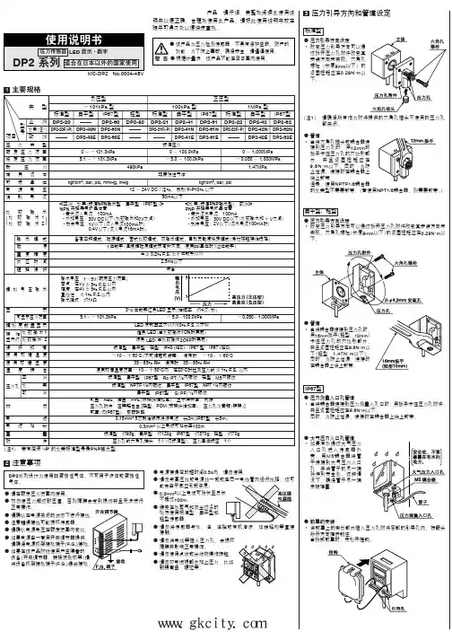
4标准型传感器安装ⅷ需要使用传感器安装支架MS-DPX 和MS-DPX-4(另售)用传感器安装支架等安装传感器时,紧固扭矩应在1.2N ⅐m 以下。
ⅷ同时也配有面板安装支架MS-DPX-2(另售)和正面防护罩DPX-04(另售)。
5I/O 电路图NPN输出型符号... D: 反向电源极性保护二极管Z D1, Z D2, Z D3: 电涌吸收齐纳二极管Tr 1, Tr 2: NPN 输出晶体管(注1):模拟电压输出不装备短路保护电路。
不可直接连接到电源或容量负荷上。
当使用模拟电压输出时,请注意连接具有适当输入阻抗的外部设备。
另外,当使用延长电缆时,由于要考虑电缆电阻,电压会下降。
PNP输出型符号... D: 反向电源极性保护二极管Z D1, Z D2, Z D3: 电涌吸收齐纳二极管Tr 1, Tr 2: PNP 输出晶体管(注1):模拟电压输出不装备短路保护电路。
不可直接连接到电源或容量负荷上。

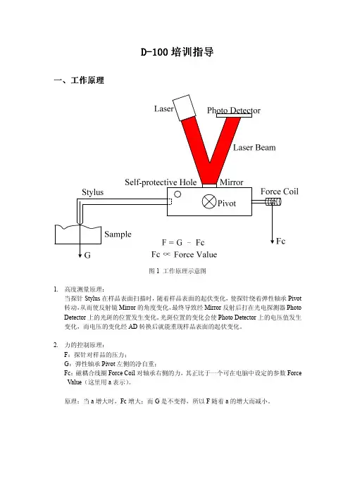
D -100培训指导培训指导一、 工作工作工作原理原理原理图1 工作原理示意图1. 高度测量原理:当探针Stylus 在样品表面扫描时,随着样品表面的起伏变化,使探针绕着弹性轴承Pivot 转动,从而使反射镜Mirror 的角度变化,最终导致经Mirror 反射后打在光电探测器Photo Detector 上的光斑的位置发生变化。
光斑位置的变化会使Photo Detector 上的电压值发生变化,而电压的变化经AD 转换后就能重现样品表面的起伏变化。
2. 力的控制原理:F :探针对样品的压力;G :弹性轴承Pivot 左侧的净自重; Fc :磁耦合线圈Force Coil 对轴承右侧的力,其正比于一个可在电脑中设定的参数Force Value (这里用a 表示)。
原理:当a 增大时,Fc 增大;而G 是不变得,所以F 随着a 的增大而减小。
二、 操作步骤 1. 仪器的启动和初始化启动电脑并将台阶仪的电源打开。
等10秒后双击桌面上的台阶仪图标 ,启动台阶仪操控软件,这时会弹出一个软件版本信息的提示框并马上消失,接着弹出一个是否要初始化的对话框,如图2,点击“Yes ”,将系统初始化。
图 2图3 D-120型台阶仪软件主界面2.2.样品的样品的样品的加载及加载及加载及定位定位定位a. 将样品放到样品台中央,然后使用X-Y Stage 控制按钮移动样品到探针正下方(D-120)或手动控制移动样品台使样品位于探针正下方(D-100)。
注意:一定要保证探针高于样品。
然后移动样品台,使样品待测区域大致地在探针正下方。
在样品上移动样品时,一定要使样品紧贴样品台表面。
探针实相探针影子 薄膜台阶扫描方向b. 点击“Engage ”键,使探针自动地缓慢下降逼近样品。
探针过高时,会出现Engage 超时警告,点击确认后再次点击即可。
当探针逼近到样品表面时,即在视频窗口中看到探针(右)针尖及其影子(左)的针尖接触上时,探针会自动停止下降逼近。
传感器培训资料第一部分:传感器的基本概念传感器是一种能够感知环境中的各种物理量并将其转化为电信号的装置。
通过测量物理量,传感器可以帮助我们获得环境中各种数据,从而实现自动化控制和监测。
传感器的种类繁多,常见的传感器包括温度传感器、湿度传感器、压力传感器、光电传感器等。
在不同的应用场景中,需要选择不同类型的传感器来完成具体的任务。
第二部分:传感器的工作原理传感器的工作原理通常通过物理效应来实现。
例如,温度传感器通常利用热敏电阻或热电偶来测量温度;压力传感器则利用压阻效应或压电效应来转换压力为电信号。
在传感器的内部,通常还会带有信号放大电路、模数转换器等元件,用来将感知到的物理量转化为标准的电信号输出。
第三部分:传感器的应用场景传感器广泛应用于工业控制、汽车领域、医疗设备等各个领域。
例如,温度传感器可以用于控制空调温度、汽车发动机的温度监测等;压力传感器可以用于测量液体或气体的压力、监测管道的泄漏等。
第四部分:传感器的选择和安装在选择传感器时,需要考虑其测量范围、精度、响应时间等指标,以及适用的工作环境,如温度、湿度等。
在安装传感器时,需要注意避免干扰源,保证传感器测量的准确性。
第五部分:传感器的维护和保养传感器作为自动化系统中的重要部件,需要进行定期的维护和保养。
对于一些易受环境影响的传感器,如湿度传感器、光电传感器等,需要保持其表面清洁,防止积灰或水汽影响测量精度。
第六部分:传感器的未来发展随着科技的不断进步,传感器的应用范围将会更加广泛,同时传感器本身的性能也将进一步提升。
例如,新型传感器可能会采用纳米技术制备,具有更高的灵敏度和更小的体积;同时,通过无线传输技术,传感器也有望实现无线监测和控制,大大提高其应用灵活性。
通过本次传感器培训,希望大家能够对传感器有更深入的了解,从而能够更好地应用传感器解决实际问题,提高工作效率和产品质量。
同时也希望大家能够关注传感器领域的最新发展,不断更新自己的知识,为行业的发展做出更大的贡献。

松下d p100具体参数设置步骤(总10页)--本页仅作为文档封面,使用时请直接删除即可----内页可以根据需求调整合适字体及大小--松下dp100具体参数设置步骤1.可同时显示两个值、直接设定基准值□30mm的紧凑机身配备双画面显示功能。
可同时确认当前值和基准值,无需切换画面模式即可顺利确认、设定基准值。
在基准值设定过程中也可进行ON/OFF动作,可以像旋钮式传感器那样进行设定。
当然,还装备锁定功能。
2.3色显示(红、绿、橙)主显示屏与输出的ON/OFF动作联动,使颜色变化,而且设定中颜色也可变化。
容易掌握传感器的状况,减少操作错误。
3.易读的数字显示采用12段字母数字显示。
英数字的辨识性得到提高4.减少工时、人为错误的复制功能通过将传感器逐台安装到主传感器上,可通过数据通信复制主传感器的设定内容。
对多个传感器进行相同设定时,可防止设定错误导致的故障,在变更装置的设计时,只需对作业指示书进行少许变更即可。
注)无法从新版本向旧版本进行复制。
可从旧版本向新版本进行复制。
优点1:削减生产开发周期!大幅削减传感器的设定时间!优点2:消除工作错误和损失!防止由于自动复制而导致设置错误和设置上错误所引起的麻烦!即使设备设计发生变化时,也可轻松修改工作指令!5.传感器的设定操作模式对应使用频率的3层结构日常进行的操作设定使用"RUN模式"、基本设定使用"菜单设定模式"、高级功能使用"PRO模式"根据设定内容的等级加以明确区分。
设定操作简单易懂。
6.设定中显示橙色RUN状态显示为绿色/红色赤色、设定中通常显示为橙色、传感器颜色一目了然。
RUN状态[RUN模式]设定中[菜单设定模式][PRO模式]7.简单的初始设定压力传感器可用于使用频率多的场合,初始设定简单。
低压型适用于吸附确认、高压型最适用于总压力确认。
减少了传感器的设置工作。
8.触感良好的按钮触感良好的按钮,设定工作流畅。
石英压力敏感元件的压力传感器研制引言谐振式石英晶体压力传感器以其高精度,良好的长期稳定性广泛应用于气压与高度测量、压力白动校准以及精密过程控制等。
这种高精度石英晶体压力传感器在结构形式上主要有2 种形式,一种是厚膜切变模式,将石英晶体加工成透镜模式,在透镜上制作电极,利用其振动频率与所受压力的变化关系来检测压力的大小,这种传感器对透镜和电极的加工工艺要求很高,产品制造难度大,现已逐渐被其他结构取代;另一种是以石英谐振梁为力敏元件,用波登管或金属膜盒来感受压力,并将压力转换成力作用到谐振梁上,谐振梁的频率随作用压力变化而变化,利用谐振梁的频率变化來检测被测压力的人小。
这种压力传感器结构较为复杂,对材料和制造工艺都要求很高,目前,国际上仅有少数儿家公司掌握了其关键技术,能够批量提供产品。
针对该传感器的制造难题,本文提出了研制全石英压力敏感元件的压力传感器,用石英弹性膜片替代复朵的金属弹性元件,降低制作难度,实现传感器小型化1传感器的结构与工作原理石英谐振式压力传感器主要由压力敏感元件和激振电路组成。
传感器的结构如图1所示,包括压力接口、压力敏感元件和壳体等。
压力敏感元件是传感器的核心,它包括弹性膜片和音叉式力敏谐振器。
当压力作用于弹性膜片吋,使膜片产生变形,导致膜片沿直径方向产生拉力或压力,并将该力作用到谐振梁上,谐振梁的频率随作用力变化而变化,利用谐振梁的频率变化来检测被测压力的大小。
压力敏感元件各部均由石英品体材料制成。
石英力敏谐振器通过光刻和化学腐蚀工艺加工完成,并采用烧结工艺装配到弹性膜片上,然后,在真空条件下,将弹性膜片烧结到已研磨出空腔的基座上,在完成基座与弹性膜片烧结同时也2石英力敏谐振器制作石英力敏谐振器是由2个外侧的支撑梁和2个内侧谐振梁构成,电极分布在谐振梁上,且分布在谐振梁的上下表面与侧而,支撐梁上没有电极。
利用铜镀层掩蔽,采用各向异性腐蚀液对石英晶体进行刻蚀。
釆用旋转蒸发方式蒸电极层,侧面电极通过增加特制侧面光源进行光刻,这样,就解决了侧电极制作难题。

BD SENSORS GmbH BD-Sensors-Straße 1 Tel.: +49 (0) 92 35 / 98 11- 0 www.bdsensors.de D - 95199 ThiersteinFax: +49 (0) 92 35 / 98 11- 11*****************DPT 100Differential Pressure Transmitter for Process Industryaccuracy according to IEC 60770: 0.1 % FSODifferential pressure from 10 mbar up to 20 bar Static pressure max. 400 bar Output signal 2-wire: 4 ... 20 mARS485 with Modbus RTU protocol Special characteristics► compact design ► fast response time ► aluminium die cast case ►zero adjustment via buttonOptional versions►several process connectionsThe differential pressure transmitter DPT 100 has been especially designed for fast test processes in leakage and flow measurement, where a fast response time and high sampling rate are necessary.The compact design of the DPT 100 facilitates the usage in standardised applications. For instance, the installation in 19" racks.The DPT 100 with optionally RS485 interface uses the communication protocol Modbus RTU which has found the way in industrial communi-cation as an open protocol. The Modbus proto-col is based on a master Slave architecture with which up to 247 Slaves can be questioned by a master – the data will transfer in binary form. Preferred areas of use are Test engineering / leak testingMachine and plant engineering Environmental technologyEnergy productionpressure measurementMiscellaneousMounting bracket (optionally) material C-steel or stainless steel 1.4401 (304)weight 0.45 kg (incl. bolts and nuts)Ingress protection IP 66 / IP 67Installation position any 2Weight approx. 1800 gCurrent consumption approx. 23 mAOperational life 100 million load cyclesCE-conformity EMC Directive: 2014/30/EU Pressure Equipment Directive: 2014/68/EU (module A) 32 Pressure transmitters are calibrated in a vertical position with the pressure connection down. If this position is changed on installation there can be slight deviations in the zero point. Press the button for zero adjustment (see operating manual).3 This directive is only valid for devices with maximum permissible overpressure > 200 bar.ConnectionsElectrical connection terminal clamps in clamping chamber (for cable-Ø max.2.5 mm²)Process connectionsStandardoption internal thread 1/4" - 18 NPT / fixing 7/16 UNFinternal thread 1/4" - 18 NPT / fixing M10 others: on requestWiring diagram2-wire-system (current)RS485 / Modbus RTUPin configurationElectrical connection terminal clamps M12x1 / metal (4-pin)Supply +Supply –for RS485 / Modbus RTU:A (+)B (–) + Ub- UbAB1324Ground plug housing Dimensions (mm / in)DPT100_E_110422 Tel.: +49 (0) 92 35 / 98 11- 0 www.bdsensors.deFax: +49 (0) 92 35 / 98 11- 11 *****************©2 0 2 2 B D | S E N S O R S G m b H –T h e s p e c i f i c a t i o n s g i v e n i n t h i s d o c u m e n t r e p r e s e n t t h e s t a t e o f e n g i n e e r i n g a t t h e t i m e o f p u b l i s h i n g . W e r e s e r v e t h e r i g h t t o m a k e m o d i f i c a t i o n s t o t h e s p e c i f i c a t i o n s a n d m a t e r i a l s .psupply +supply –V S = 12 ... 32 V DC Isupply+psupply–V S = 9 ... 32 V DCA (+)B (-)RS 485www.bdsensors.de-----------34510 mbar 010060 mbar 0600100 mbar 1000400 mbar 40002.5 bar 250120 bar2002-10 … 10 mbar S 010-60 … 60 mbar S 060-100 … 100 mbar S 100-400 … 400 mbarS 400customer9999consult1L59consultp N ≥ 60 mbar:0.1 % FSO 1p N < 60 mbar:0.2 % FSO B customer9consultaluminium L customer9consultA K 2M 17customer999consultN 20N 21N 30N 31customer999consult012with vent (bottom)31299consult1199consultFKM 1EPDM 3NBR 5PTFE 4customer9consult000999consult11.04.2022standard customerstainless steel 1.4435 (316L) / silicone oilcustomer1/4" - 18 NPT F / fixing 7/16 UNF1/4" - 18 NPT (F / vertical) / fixing M10terminals / cable gland M12x1.5male plug M12x1 (4-pin) / metalwithout customer1/4" - 18 NPT (F / vertical) / fixing 7/16 UNF1/4" - 18 NPT F / fixing M10© 2022 B D |S E N S O R S G m b H - T h e s p e c i f i c a t i o n s g i v e n i n t h i s d o c u m e n t r e p r e s e n t t h e s t a t e o f e n g i n e e r i n g a t t h e t i m e o f p u b l i s h i n g . W e r e s e r v e t h e r i g h t t o m a k e m o d i f i c a t i o n s t o t h e s p e c i f i c a t i o n s a n d m a t e r i a l s .DPT 100RS485 Modbus RTU4 … 20 mA / 2-wire customerdifferential pressurestainless steel 1.4401 (316 SS)with vent with vent (top)。


3B SCIENTIFIC ® PHYSICS1Instruction sheet10/15 Hh∙To avoid permanent damage to the internal semiconductor sensor, the maximum permitted relative pressure of 4000 hPa must never be exceeded.Only suitable for use with non-corrosive gases such as air, helium or nitrogen.∙ Do not allow the sensor element tocomeinto contact with water. Relative pressure sensor with a measurement range up to 100 hPa, suitable for measuring the pressure on the piston of the Stirling engine D 1000817 (for a pV diagram).For two-port measurement using the sensor, hose connections are provided for two inputs. The sensor box is designed to be detected automatically by the 3B NET logTM unit. 1 Sensor box1 MiniDIN 8-pin connector cable, 60 cm long 1 Silicone hose, internal diameter2 mm, 1 m longMeasurement range: ± 100 hPaSensor type: Semiconductor sensor Accuracy: ± 1 % Resolution: ± 1 hPaConnections:2 hose connections, 4.8 mm diameter∙ Cut the silicone hose into sections of the required length.∙Using the lengths of hose, make the pressure connections between the sensor box and the Stirling engine.∙Note the “positive” and “negative” label ling of the hose connections - connect the hoses correctly according to the effective direction of the pressure.∙During the experiment, check that no elastic expansion of the hose is occurring – this can cause the pressure reading to be lower than the correct value.3B Scientific GmbH ∙ Rudorffweg 8 ∙ 21031 Hamburg ∙ Germany ∙ Subject to technical amendments© Copyright 2008 3B Scientific GmbHMeasurement of the pressure difference in the Stirling engine D 1000817, and analysis of the data using 3B NET lab TM .Recording operating pressures in Stirling engine 1000817 while it is in motion Apparatus required:1 3B NETlogTM @230 V 1000540 or1 3B NETlogTM @115 V 1000539 1 3B NET lab TM 1000544 1 Relative pressure sensor, ±100 hPa 1000547 1 Stirling engine D 1000817∙ Set up the experiment as shown in fig. 1. ∙ Connect the relative pressure sensor to the3B NET log TM unit and wait for the sensor to be detected.∙ Use a suitable length of silicone hose tomake the pressure connection between the “positive” hose connection of the sensor box and one of the two hose connections of the Stirling engine. The two hose connections of the engine are identical in their function.∙ Allow the engine to heat up and, after afew minutes, set it running.∙Open the application program (template) for the experiment with the ±100 hPa relative pressure sensor on the 3B NET lab TM unit.∙Measure the pressures.∙Evaluate the curve resulting from the measurements (fig. 2).Fig. 1 Experiment set-up for recording operating pressures in the Stirling engine D while in motionFig. 2 Trace of pressure in the Stirling engine D。