ASTM G48-2011(R2015)使用三氯化铁溶液做不锈钢及其合金的耐点腐蚀和抗缝隙腐蚀性试验的标准方法
- 格式:docx
- 大小:142.03 KB
- 文档页数:17

ASTM G48-2011(R2015)使用三氯化铁溶液做不锈钢及其合金的耐点腐蚀和抗缝隙腐蚀性试验的标准方法(中文翻译版)本标准以固定名称G48发布;紧跟在名称后面的数字表示最初采用的年份,如果是修订,则表示最后修订的年份。
括号中的数字表示上次重新批准的年份。
上标(ε)表示自上次修订或重新批准以来的编辑性更改。
1.范围1.1本试验方法包括若干测定规程,用于测定不锈钢及其台金暴露于氯-氧化环境时的耐麻点和缝隙腐蚀性(见术语G15)。
介绍六种规程,命名为方法A、B、C、D、E和F。
1.1.1方法A——三氯化铁点腐蚀试验。
1.1.2方法B——三氯化铁缝隙腐蚀试验。
1.1.3方法C——镍基和铬包复合金的临界点腐蚀温度试验。
1.1.4方法D——镍基和铬包复合金的临界缝隙腐蚀温度试验。
1.1.5方法E——不锈钢的临界点腐蚀温度试验。
1.1.6方法F——不锈钢的临界缝隙腐蚀温度试验。
1.2方法A用于测定不锈钢和镍基、铬包复合金的相对耐点腐蚀性,方法B可用于侧定这些合金的耐麻点和缝隙腐蚀性。
方法C、D、E 和F可在标准三氯化铁溶液中,按导致不锈钢、镍基和铬包复合金各自开始点腐蚀和缝隙腐蚀的最低(临界)温度,为这些合金划分等级。
1.3这些试验可用于测定合金填加剂、热处理和表面光洁度对耐点腐蚀性和耐缝隙腐蚀性的影响。
1.4以SI单位表示的值被认为标准。
在括号中给出其它单位,仅供参考。
1.5本标准并不意味已提及与其使用相关的所有安全事项。
制定合适的安全和健康规范,确定规章限制的适用性,是本标准用户的职责。
2.引用文件2.1 ASTM标准A262检测奥氏体不锈钢晶间腐蚀敏感性规范D1193试剂水技术规范E691进行实验室间研究以测定试验方法精度的规范E1338计算机化材料性能数据库中金属与合金识别指南G1制备、清洗和评估腐蚀拭验试样的规范G15与腐蚀和腐蚀试验相关的术语(2010年撤回)33该历史标准的最新批准版本在上引用。

不锈钢三氯化铁点腐蚀试验实验原理引言:不锈钢是一种常用的金属材料,其具有良好的耐腐蚀性能,但在特定环境中,仍然可能发生腐蚀现象。
为了评估不锈钢材料的耐腐蚀性能,可以使用不锈钢三氯化铁点腐蚀试验进行实验。
本文将介绍不锈钢三氯化铁点腐蚀试验的实验原理。
实验原理:不锈钢三氯化铁点腐蚀试验是一种常用的实验方法,用于评估不锈钢材料的耐腐蚀性能。
实验过程中,首先需要准备好试样,通常采用直径为10mm的不锈钢圆片。
然后,在试样表面涂覆一层不锈钢三氯化铁溶液。
三氯化铁是一种强氧化剂,可以引发不锈钢表面的点腐蚀反应。
实验过程中,试样在三氯化铁溶液中浸泡一段时间后取出,观察试样表面是否出现腐蚀斑点。
若试样表面出现腐蚀斑点,则说明不锈钢材料在该环境中存在点腐蚀现象,耐腐蚀性能较差;若试样表面未出现腐蚀斑点,则说明不锈钢材料在该环境中具有良好的耐腐蚀性能。
实验原理解析:不锈钢三氯化铁点腐蚀试验的原理是利用强氧化剂三氯化铁引发不锈钢表面的点腐蚀反应。
不锈钢具有一层致密的氧化铬膜,可以防止金属内部的氧化反应。
然而,在特定环境中,例如氯化物存在的酸性环境中,氧化铬膜可能被破坏,导致不锈钢表面的点腐蚀。
三氯化铁作为一种强氧化剂,可以提供足够的氧化剂给不锈钢表面的点腐蚀反应。
当不锈钢试样与三氯化铁溶液接触时,三氯化铁会在不锈钢表面引发氧化反应,破坏氧化铬膜。
在破坏的区域,金属表面暴露在溶液中,易于发生点腐蚀反应。
通过观察试样表面是否出现腐蚀斑点,可以评估不锈钢材料的耐腐蚀性能。
若试样表面出现腐蚀斑点,则说明不锈钢材料在该环境中容易发生点腐蚀,耐腐蚀性能较差;若试样表面未出现腐蚀斑点,则说明不锈钢材料在该环境中具有良好的耐腐蚀性能。
结论:不锈钢三氯化铁点腐蚀试验是一种用于评估不锈钢材料耐腐蚀性能的实验方法。
实验原理是利用强氧化剂三氯化铁引发不锈钢表面的点腐蚀反应。
通过观察试样表面是否出现腐蚀斑点,可以评估不锈钢材料的耐腐蚀性能。
这种实验方法简单易行,可以在实验室中进行,对于不锈钢材料的耐腐蚀性能评估具有重要意义。
焊接参数对2205双相钢焊接接头理化性能的影响2205双相不锈钢凭借优越的力学性能和耐蚀性能已得到广泛应用,双相钢的焊接技术也随着行业的发展而得以深入,该材料焊接工序复杂,工艺要求高,加上双相钢设备焊接的特殊性和现场条件的限制,施焊难度很大,为了保证焊接接头的优良性能,控制焊接热循环,注意焊接的质量控制要点成为了焊接施工的关键。
以本文主要分析的就是焊接参数对2205双相钢焊接接头理化性能的影响,进而提出以下内容,希望能够为同行业工作人员提供相应的参考价值。
标签:焊接参数;2205;双相焊接;接头理化性能;分析1导言双相不锈钢焊接接头的力学性能及耐点蚀性能与焊缝中的两相比例密切相关,而焊接热输入则对双相组织的平衡起着关键作用。
由于双相不锈钢在高温固态下是稳定的铁素体组织,冷却过程中才会生成奥氏体,焊接时若使用过小的热输入,热影响区的快速冷却将导致奥氏体来不及析出,铁素体含量过高,冲击韧性下降;若使用过大的热输入,则会使冷却速度太慢,延长焊缝高温停留时间,虽然能够得到足够的奥氏体,但会导致铁素体晶粒长大以及σ相等脆性相的析出,造成焊接接头脆化。
2 2205双相钢高压空冷器制造技术要求2.1采用比标准更严格的硬度值控制以及更合适的硬度检测方法2.1.1硬度值控制大多标准中对2205材料规定硬度值均在HRC29-HRC31,较高的硬度对材料的轧制、焊接及使用会产生不利影响,从出现损伤的设备实际检测中,其硬度值可达到HRC30以上。
因此,在采用2205材料制造加氢高压空冷器的技术要求中应提出硬度控制要求,从产品的实际数据来看,母材和焊接接头的硬度值控制在不大于HRC25更为合适。
2.1.2硬度检测方法双相钢的硬度检测方法目前主要采用Rock-wellC和Vickers两种方法,由于双相钢材料的特性,一般不采用HBW。
维氏硬度和洛氏硬度之间的换算关系也不能采用ASTME140的规定。
2.2腐蚀试验方法的选择及要求用于炼油设备的双相钢腐蚀试验主要有ASGM48-2003《使用三氯化铁溶液测定不锈钢及合金耐点蚀和抗缝隙腐蚀试验的标准方法》。

耐蚀合金是一种能够在恶劣环境下保持耐蚀性能的特殊材料。
它被广泛应用于化工、石油、航空航天等领域,在保证设备安全运行的同时,减少了设备维修和更换的频率,降低了成本。
为了确保耐蚀合金材料的质量和性能,有一些相关的标准可以作为参考。
1.ASTM G48 - 这个标准给出了评估耐蚀合金之间的耐蚀性能的测试方法。
它涵盖了各种环境条件下的实验,包括浸泡、旋转试样和自由腐蚀试验。
这些测试方法可以用来衡量耐蚀合金材料的耐蚀性能,并对其进行比较和分类。
2.ASTM A262 - 这个标准是用于评估耐蚀合金的晶间腐蚀倾向性的试验方法。
它包括了五种试验方法,用于检测材料是否具有晶间腐蚀破坏的倾向,这是一种常见的耐蚀合金材料的问题。
3.ASTM B117 - 这个标准是用于评估耐蚀合金在盐雾环境下的耐蚀性能的试验方法。
盐雾环境是一种常见的腐蚀环境,对于耐蚀合金材料的评估非常重要。
这个标准提供了一种可重复的试验方法,用于比较不同合金材料在盐雾环境下的性能。
4.NACE MR0175 - 这个标准是由国际腐蚀与保护协会(NACE)制定的,适用于耐蚀合金在油气工业中的应用。
它规定了耐蚀合金材料的化学成分、硬度、热处理和耐蚀性能要求,以及监测、检查和验证的方法。
5.ISO 15156 - 这个标准是使用NACE MR0175作为基础,在国际范围内遵循腐蚀和材料性能规范的指南。
它适用于涉及油气开采和相关产业的设备和材料,规定了材料的选用、测试和处理要求。
6.ASME B16.34 - 这个标准规定了阀门材料的要求,包括耐蚀合金。
它涵盖了各种不同类型(例如钢、不锈钢、镍合金等)的阀门材料,以及与耐蚀性有关的其他要求,如抗硫化物应力开裂和高温环境下的耐蚀性能。
这些标准提供了评估和比较耐蚀合金材料性能的指导,可以帮助制造商、设计师和使用者选择合适的材料,并确保其耐蚀性能满足特定环境下的要求。
这些标准还可用于监督和控制耐蚀合金材料的生产和使用,确保产品质量和安全性。

使用三氯化铁溶液做不锈钢及其合金的耐麻点腐蚀和抗裂口腐蚀性试验的标准方法本标准在固定代号G48下发行;紧随此代号之后的号码表示原正式通过的年份,或在修订版情况下,表示最新修订版年份。
括号中的数字表示最新复审年份。
上标ε表示自上次修订或重审以来的编辑变更。
1范围1 .1本试验方法包括若干测定规程,用于测定不锈钢及其台金暴露于氯-氧化环境时的耐麻点和裂口腐蚀性(见术语CL5)。
介绍六种规程,命名为方法A、B、C、D、E和F。
1 .1 .1方法A——三氯化铁麻点腐蚀试验。
方法B——三氯化铁裂口腐蚀试验。
方法C——镍基和铬包复合金的临界麻点腐蚀温度试验。
1.1.4 方法D——镍基和铬包复合金的临界裂口腐蚀温度试验。
1.1.5 方法E——不锈钢的临界麻点腐蚀温度试验。
1.1.6 方法F——不锈钢的临界裂口腐蚀温度试验。
方法A用于测定不锈钢和镍基、铬包复合金的相对耐麻点腐蚀性,方法B可用于侧定这些合金的耐麻点和裂口腐蚀性。
方法C、D、E和F可在标准三氯化铁溶液中,按导致不锈钢、镍基和铬包复合金各自开始麻点腐蚀和裂口腐蚀的最低(临界)温度,为这些合金划分等级。
1 .3 这些试验可用于测定合金填加剂、热处理和表面光洁度对耐麻点腐蚀性和耐裂口腐蚀性的影响。
以SI单位表示的值被认为标准。
在括号中给出其它单位,仅供参考。
本标准并不意味已提及与其使用相关的所有安全事项。
制定合适的安全和健康规范,确定规章限制的适用性,是本标准用户的职责。
2 引用文件ASTM标准A262 检测奥氏体不锈钢晶间腐蚀敏感性规范②。
D1193 试剂水技术规范③。
E691 进行实验室间研究以测定试验方法精度的规范④。
E1338 计算机化材料性能数据库中金属与合金识别指南⑤。
G1 制备、清洗和评估腐蚀拭验试样的规范⑥。
G15 与腐蚀和腐蚀试验相关的术语⑦。
G46 麻点腐蚀检验和评估指南⑧。
G107 计算机化数据库输入用金属腐蚀数据采集和编辑格式准则⑨。

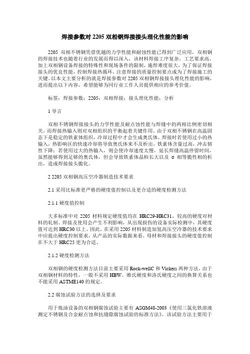
x x x钢业有限公司xxx Steel Co.,Ltd点腐蚀试验报告Piting Corrosion Testing Report产品名称Product Name 奥氏体-铁素体双相钢Austenitic-ferriticduplex steel pipe牌号Type S32750规格Sizeφ273.05*9.27炉号Heat No. FK1909-109生产批号Batch No.20B5-889合同编号Contract No.---试验标准Testing Basis ASTM G48 A法,16ml盐酸+6%三氯化铁溶液24小时50℃点腐蚀/ASTM G48 A method,16ml HCl+6%ferric chloride solution 24 hours50℃pitting corrosion产品标准ProductStandardASTM A790试样尺寸SampleDimensions(mm)L:39.70mm×S:9.22mm×W29.92mm 试样面积0.00366m2试验时间Test Hours 24小时试验温度Temperature50℃试验前试重量Sample weightbefore test83.4415g试验数据Test Data:入瓶时间Time in bottle 2020-06-27 16:30 出瓶时间Time out bottle 2020-06-28 16.30出瓶后重量weight after out bottle83.4322g 损重weight loss 0.0093g损重率weight lost rateg/m20.0093g÷0.00366 m2=2.5409836 g/m2≈2.541 g/m2损重率weight lost rateg/ m2/h2.541 g/m2÷24h=0.106 g/ m2/h判定参考数值Reference value≤4.0g g/m2判定judgment 合格附:试样出瓶后状态图,未见明显腐蚀坑Attachment: The state diagram after the sample is out of the bottle, no obvious corrosion pits试验员Inspector 日期Date审核Review by日期Date。

ASTM标准的中文版本目录ASTM A6/A6M-2004 a结构用轧制钢板、型钢、板桩和棒钢通用要求ASTM A36/A36M-2004碳结构钢标准规范ASTM A106-2002a高温用无缝碳钢公称管规范ASTM A143-2003热侵镀锌结构钢制品防脆化的标准实施规程和催化探测方法ASTM A179/A179M-1990a(R2001)热交换器和冷凝器用无缝冷拉低碳钢管标准规范ASTM A192-2002高压设备用无缝碳钢锅炉管标准规范ASTM A209/A209M-2003锅炉和过热器用无缝碳钼合金钢管标准规范ASTM A210/A210M-2003锅炉和过热器用无缝中碳钢管技术条件ASTM A213/A213Mb-2004锅炉过热器和换热器用无缝铁素体和奥氏体合金钢传热管技术条件ASTM A234/A234M-2004中、高温用锻制碳钢和合金钢管道配件ASTM A252-98(R2002)焊接钢和无缝钢管桩的标准规范ASTM A262-2002a探测奥氏体不锈钢晶间腐蚀敏感度的标准实施规范ASTM A269/A269-2004通用无缝和焊接奥氏体不锈钢管标准规范ASTM A333/A333M-2004低温设备用无缝和焊接钢管的规范标准ASTM A334/A334M-2004低温设备用无缝和焊接碳素和合金钢管的标准规范ASTM A335-2003高温设备用无缝铁素体合金钢管标准规范ASTM A370/A370M-2003a钢制品力学性能试验方法和定义标准ASTM A387/A387M-2003压力容器用铬钼合金钢板的标准规范ASTM A403/A403M-2004锻制奥氏体不锈钢管配件的标准规范ASTM A450/A450M-2004碳素钢管、铁素体合金钢管及奥氏体合金钢管一般要求的标准规范ASTM A500-2003a圆形与异型冷成型焊接与无缝碳素钢结构管标准规范ASTM A515-2003中温及高温压力容器用碳素钢板的标准规范ASTM A516-2004a中温及低温压力容器用碳素钢板的标准规范ASTM A530-2003特种碳素钢和合金钢管一般要求的标准规范ASTM A615/A615M-2004a混凝土配筋用异形钢筋和无节钢胚棒标准规范ASTM A703/A703M-2004标准技术条件—承压件钢铸件通用要求ASTM A781/A781M-2004a铸件、钢和合金的标准规范及通用工业的一般性要求ASTM A788/A788M-2004a标准技术条件—钢锻件通用要求ASTM B209/B209M -2004铝和铝合金薄板和中厚板标准规范ASTM E6-2003金属材料布氏硬度的标准测试方法ASTM E18-2003金属材料洛氏硬度和洛氏表面硬度的标准测试方法ASTM E29-2002使用有效数字确定试验数据与规范符合性作法ASTM E8-2004金属材料拉伸试验的标准测试方法ASTM E94-2004放射性检查的标准指南ASTM E125-1963(R2003)铁铸件的磁粉检验用标准参考照片ASTM E164-2003焊件的超声接触检验的标准操作规程ASTM E208-1995a(R2000)用导向落锤试验测定铁素体钢无塑性转变温度的标准试验方法ASTM E213-2004金属管超声检验方法ASTM F36-1995测定垫片材料压缩率及回弹率的标准试验方法ASTM F37-1995垫片材料密封性的标准试验方法ASTM F38-1995垫片材料的蠕变松弛的标准试验方法ASTM F112-1995色覆垫片密封性能的标准试验方法ASTM F146-1995a垫片材料耐液体标准试验方法ASTM F1311-1995(R2001)大口径组装式碳钢法兰标准规范ASTM G1-2003腐蚀试样的制备、清洁处理和评定用标准实施规范ASTM G36-73(R1981) 参考资料标准实用规程:在沸的氯化镁溶液中进行的应力腐蚀裂纹试验ASTM G46-1976(R1986) 参考资料标准实用规程:麻点腐蚀的检验和评定ASTM G48-1976(R1980) 参考资料使用三氯化铁溶液做不锈钢及其合金的耐麻点腐蚀和抗裂口腐蚀性试验的标准方法ASTM标准中译本丛书(一)碳钢、铸铁、不锈钢及合金钢材料标准规范(含18个标准)ASTM A105/A105M-2002管道部件用碳钢锻件ASTM A126-1995(R2001)阀门、法兰和管道附件用灰铁铸件ASTM A181/A181M-2001通用管路用碳钢锻件标准规范ASTM A193/A193M-2001高温用合金钢和不锈钢螺栓材料ASTM A194/A194M-2001 a高温用合金钢和不锈钢螺栓材料ASTM A216/A216M-2001 a高温用可熔焊碳钢铸件标准规范ASTM A217/A217M-2002高温承压件用马氏体不锈钢和合金钢铸件标准规范ASTM A276-2002 a不锈钢棒材和型材ASTM A278/A278M-2001高温不超过650°F(350℃)的承压部件用灰铸铁件ASTM A320/A320M-2002低温用合金钢栓接材料ASTM A350/A350M-2002要求冲击韧性试验的管件用碳钢及低合金钢锻件标准规范ASTM A351/A351M-2000承压件用奥氏体、奥氏体-铁素体(双相)钢铸件规范ASTM A352/A352M-1993(R1998)低温承压件用铁素体和马氏体钢铸件标准规范ASTM A395/A395M-1999高温用铁素体球墨铸铁承压铸件ASTM A439-1983(R1999)奥氏体球墨铸铁件ASTM A536-1984(R1999)球墨铸铁件ASTM A694/A694M-2000高温输送用管法兰、管件、阀门及零件用碳钢和合金钢锻件标准规范ASTM A965/A965M-2002高温高压部件用奥氏体钢锻件ASTM标准中译本丛书(二)法兰、管件、阀门及部件(含9个标准)ASTM A182/A182M-2002高温用锻制或轧制合金钢法兰、锻制管件、阀门和部件ASTM A961-2002管道用钢制法兰、锻制管件、阀门和零件的通用要求标准规范ASTM B462-2002高温耐腐蚀用锻制或轧制的UNS NO6030、UNS NO6022、UNS NO6200、UNSNO8020、UNS NO8024、UNS NO8026、UNS NO8367、UNS NO10276、UNS N10665、UNS N10675和UNS R20033合金管法兰、锻制管件、阀门和零件标准规范ASTM F885-1984公称管径为NPS 1/4~2的青铜截止阀外形尺寸标准规范ASTM F992-1986(R2001)阀门铭牌标准规范ASTM F993-1986(R2001)阀门锁紧装置标准规范ASTM F1030-1986(R1998)阀门操作装置的选择准则ASTM F1098-1987(R1998)公称管径有NPS2~24的蝶阀外形尺寸标准规范ASTM F1565-2000蒸汽用减压阀规范。

ASTM美国标准ASTM E426-1998(2007重新审批) 无缝及焊接管产品、沃斯田不锈钢及类似合金的电磁(涡电流)检测操作规程(Standard Practice for Electromagnetic (Eddy-Current) Examination of Seamless and Welded Tubular Products, Austenitic Stainless Steel and Similar Alloys)ASTM A53/A53M-2005版无镀层及热浸镀锌焊接与无缝公称钢管标准技术条件ASTM A105/A105M-2005版管道部件用碳钢锻件ASTM A106-2006版高温用无缝碳钢公称管规范ASTM A108-2003版冷精整的碳钢和合金钢棒材标准技术条件ASTM A123/A123M-2002版钢铁产品镀锌品层(热浸镀)标准规范ASTM A126-2004版阀门、法兰和管道附件用灰铁铸件ASTM A143-2003版热浸镀锌结构钢制品防脆化的标准实施规程和催化探测方法ASTM A153/A153M-2005版钢铁构件镀锌层(热浸镀)标准规范ASTM A179/A179M-1990a(R2001)版热交换器和冷凝器用无缝冷拉低碳钢管标准规范ASTM A192-2002版高压设备用无缝碳钢锅炉管标准规范ASTM A193/A193M-2006版高温用合金钢和不锈钢螺栓材料ASTM A194/A194M-2006版高温或高压或高温高压螺栓用碳钢及合金钢螺母标准规范ASTM A209/A209M-2003版锅炉和过热器用无缝碳钼合金钢管标准规范ASTM A210/A210M-2002版无缝中碳钢锅炉管和过热器管标准规范ASTM A213/A213Mb-2004版无缝铁素体和奥氏体合金钢锅炉管、过热器管和换热器管标准规范ASTM A216/A216M-2004版高温用可熔焊碳钢铸件标准规范ASTM A234/A234M-2004版中、高温用锻制碳钢和合金钢管道配件ASTM A240/A240M-2005版压力容器用耐热铬及铬-镍不锈钢钢板、薄板和钢带标准技术条件ASTM A250/A250M-2004版锅炉和过热器用电阻焊铁素体碳合金钢管子标准技术条件ASTM A252-98(R2002)版焊接钢和无缝钢管桩的标准规范ASTM A269/A269-2004版通用无缝和焊接奥氏体不锈钢管标准规范ASTM A276-2006版不锈钢棒材和型材标准规范ASTM A283/A283M-2003版中、低抗拉强度碳素钢板标准技术条件ASTM A285/A285M-2003版压力容器用中、低抗拉强度碳素钢标准技术条件ASTM A307/A307M-2004版抗拉强度6000PSI碳钢螺栓和螺柱标准技术条件ASTM A312/A312M-2005版无缝和焊接的以及重度冷加工奥氏体不锈钢公称管标准技术条件ASTM A320/A320M-2005版低温用合金钢栓接材料标准规范ASTM A333/A333M-2004版低温设备用无缝和焊接钢管的规范标准ASTM A334/A334M-2004版低温设备用无缝和焊接碳素和合金钢管的标准规范ASTM A335-2003版高温设备用无缝铁素体合金钢管标准规范ASTM A336/A336M-2005版高温承压件合金钢锻件标准技术条件ASTM A350/A350M-2004a版需切口韧性试验的管道部件用碳钢和低合金钢锻件标准规范ASTM A351/A351M-2006版承压件用奥氏体铸钢件标准规范ASTM A352/A352M-2006版低温承压用铁素体和马氏体铸钢件标准规范ASTM A356/A356M-2005版汽轮机用厚壁碳钢、低合金钢和不锈钢铸件标准技术条件ASTM A387/A387M-2003版压力容器用铬钼合金钢板的标准规范ASTM A403/A403M-2004版锻制奥氏体不锈钢管配件的标准规范ASTM A450/A450M-2004版碳素钢管、铁素体合金钢管及奥氏体合金钢管一般要求的标准规范ASTM A479/A479M-2005版锅炉和其他压力容器用不锈钢棒材和型材标准技术条件ASTM A484/A484M-2005版不锈钢棒材、钢坯及锻件通用要求标准技术条件ASTM A500-2003a版圆形与异型冷成型焊接与无缝碳素钢结构管标准规范ASTM A515-2003版中温及高温压力容器用碳素钢板的标准规范ASTM A516-2004a版中温及低温压力容器用碳素钢板的标准规范ASTM A519-2003版机械工程用碳素钢和铝合金钢无缝钢管ASTM A530-2003版特种碳素钢和合金钢管一般要求的标准规范ASTM A577/A577M-90(R2001)版钢板超声斜射波检验ASTM A589/A589M-2006版打水井用碳素钢无缝钢管和焊接钢管ASTM B462-2004版高温耐腐蚀用锻制或轧制的UNS NO6030、UNS NO6022、UNS NO6200、UNS NO8020、UNS NO8024、UNS NO8026、UNS NO8367、UNS NO10276、UNS N10665、UNS N10675和UNS R20033合金管法兰、锻制管件、阀门和零件标准规范ASTM E164-2003版焊件的超声接触检验的标准操作规程ASTM E208-1995a(R2000)版用导向落锤试验测定铁素体钢无塑性转变温度的标准试验方法ASTM E213-2004版金属管超声检验方法ASTM E273-2001版焊接公称管和管子制品超声波检验用标准实用规程ASTM F1311-1990(R2001)版大口径组装式碳钢法兰标准规范ASTM G1-2003版腐蚀试样的制备、清洁处理和评定用标准实施规范ASTM G36-73(R1981) 参考资料标准实用规程:在沸的氯化镁溶液中进行的应力腐蚀裂纹试验ASTM G46-1976(R1986) 参考资料标准实用规程:麻点腐蚀的检验和评定ASTM G48-2003版使用三氯化铁溶液做不锈钢及其合金的耐麻点腐蚀和抗裂口腐蚀性试验的标准方法ASTM标准(一)碳钢、铸铁、不锈钢及合金钢材料标准规范(含18个标准)1. ASTM A105/A105M-2002版管道部件用碳钢锻件2. ASTM A126-1995(R2001)版阀门、法兰和管道附件用灰铁铸件3. ASTM A181/A181M-2001 版通用管路用碳钢锻件标准规范4. ASTM A193/A193M-2001版 ?高温用合金钢和不锈钢螺栓材料5. ASTM A194/A194M-2001a版高温、高压或高温高压螺栓用碳钢及合金钢螺母标准规范6. ASTM A216/A216M-2001a版高温用可熔焊碳钢铸件标准规范7. ASTM A217/A217M-2002 版高温承压件用马氏体不锈钢和合金钢铸件标准规范8. ASTM A276-2002a版不锈钢棒材和型材9. ASTM A278/A278M-2001版高温不超过650°F(350℃)的承压部件用灰铸铁件10. ASTM A320/A320M-2002 版低温用合金钢栓接材料11. ASTM A350/A350M-2002 版要求冲击韧性试验的管件用碳钢及低合金钢锻件标准规范12. ASTM A351/A351M-2000 版承压件用奥氏体、奥氏体-铁素体(双相)钢铸件规范13. ASTM A352/A352M-1993(R1998)版低温承压件用铁素体和马氏体钢铸件标准规范14. ASTM A395/A395M-1999 版高温用铁素体球墨铸铁承压铸件15. ASTM A439-1983(R1999)版奥氏体球墨铸铁件16. ASTM A536-1984(R1999)版球墨铸铁件17. ASTM A694/A694M-2000? 版高温输送用管法兰、管件、阀门及零件用碳钢和合金钢锻件标准规范18. ASTM A965/A965M-2002 版高温高压部件用奥氏体钢锻件ASTM标准法兰、管件、阀门及部件(含9个标准)1. ASTM A182/A182M-2002版高温用锻制或轧制合金钢法兰、锻制管件、阀门和部件2. ASTM A961-2002版管道用钢制法兰、锻制管件、阀门和零件的通用要求标准规范3. ASTM B462-2002版高温耐腐蚀用锻制或轧制的UNS NO6030、UNS NO6022、UNS NO6200、UNS NO8020、UNS NO8024、UNS NO8026、UNS NO8367、UNS NO10276、UNS N10665、UNS N10675和UNS R20033合金管法兰、锻制管件、阀门和零件标准规范4. ASTM F885-1984(R2002)版公称管径为NPS 1/4~2的青铜截止阀外形尺寸标准规范5. ASTM F992-1986(R2001)版阀门铭牌标准规范6. ASTM F993-1986(R2001)版阀门锁紧装置标准规范7. ASTM F1030-1986(R1998)版阀门操作装置的选择准则8. ASTM F1098-1987(R1998)版公称管径有NPS2~24的蝶阀外形尺寸标准规范9. ASTM F1565-2000版蒸汽用减压阀规范。

ASTM美国材料标准中文版ASTM A488/A488-2007 钢铸件焊接工艺和人员资格评定的标准实施规程(Standard Practice for Steel Castings, Welding, Qualifications of Procedures and Personnel)ASTM A802/A 802M-1995(R2006重新审批) 视觉检测铸钢表面验收标准规程(STANDARD PRACTICE FOR STEEL CASTINGS, SURFACE ACCEPTANCE STANDARDS, VISUAL EXAMINATION)ASTM B108-2006 铝合金永久型铸件标准规范(STANDARD SPECIFICATION FOR ALUMINUM-ALLOY PERMANENT MOLD CASTINGS)ASTM B179-2006 铸造用铝合金原锭及熔融锭在各铸造过程的标准技术规范(STANDARD SPECIFICATION FOR ALUMINUM ALLOYS IN INGOT AND MOLTEN FORMS FOR CASTINGS FROM ALL CASTING PROCESSES)ASTM B26/B26M-2005 铝合金砂铸件标准规范(STANDARD SPECIFICATION FOR ALUMINUM-ALLOY SAND CASTINGS)ASTM D256-2006 测定塑料抗悬臂梁摆锤冲击性的标准试验方法(STANDARD TEST METHODS FOR DETERMINING THE IZOD PENDULUM IMPACT RESISTANCE OF PLASTICS)ASTM D2794-1993(R2004) 有机涂层抗快速形变(冲击)作用的标准试验方法(STANDARD TEST METHOD FOR RESISTANCE OF ORGANIC COATINGS TO THE EFFECTS OF RAPID DEFORMATION (IMPACT) )ASTM D3359-2008 胶带试验用测定粘合性的标准试验方法(STANDARD TEST METHODS FOR MEASURING ADHESION BY TAPE TEST)ASTM D3363-2005 铅笔试验法测定涂膜硬度的标准试验方法(STANDARD TEST METHOD FOR FILM HARDNESS BY PENCIL TEST)ASTM D4060-2007 用泰伯尔磨蚀机测定有机涂层耐磨性的标准试验方法(STANDARD TEST METHOD FOR ABRASION RESISTANCE OF ORGANIC COATINGS BY THE TABER ABRASER)ASTM D4674-2002A 暴露在室内办公室环境下的塑料颜色稳定性加速试验的标准实施规范(STANDARD TEST METHOD FOR ACCELERATED TESTING FOR COLOR STABILITY OF PLASTICS EXPOSED TO INDOOR OFFICE ENVIRONMENTS)ASTM D4752-2003 用溶剂擦试法测定硅酸乙酯(无机)富锌底漆耐甲乙酮的标准试验方法(STANDARD TEST METHOD FOR MEASURING MEK RESISTANCE OF ETHYL SILICATE (INORGANIC) ZINC-RICH PRIMERS BY SOLVENT RUB)ASTM D4828-1994E1(R2003) 有机覆层实际可洗性的标准试验方法(STANDARD TEST METHODS FOR PRACTICAL WASHABILITY OF ORGANIC COATINGS)ASTM D638-2003 塑料拉伸性能标准测试方法(STANDARD TEST METHOD FOR TENSILE PROPERTIES OF PLASTICS)ASTM E1316-2007 无损检测标准术语(STANDARD TERMINOLOGY FOR NONDESTRUCTIVE EXAMINATIONS)ASTM E1444-2005 磁粉检测标准规程(STANDARD PRACTICE FOR MAGNETIC PARTICLE TESTING)ASTM E155-2005 铝、镁铸件检验用标准参考射线底片(STANDARD REFERENCE RADIOGRAPHS FOR INSPECTION OF ALUMINUM AND MAGNESIUM CASTINGS)ASTM E165-2002 液体渗透剂检查标准测试方法(STANDARD TEST METHOD FOR LIQUID PENETRANT EXAMINATION)ASTM E165-2002 液体渗透检查的标准试验方法王倩译(STANDARD TEST METHOD FOR LIQUID PENETRANT EXAMINATION)ASTM E192-2004 航天设备蜡模钢铸件的参考放射线照相(STANDARD REFERENCE RADIOGRAPHS OF INVESTMENT STEEL CASTINGS FOR AEROSPACE APPLICATIONS)ASTM E242-2001(2005年重新批准) 在某些参数变化时射线图像外观用标准参考射线底片(STANDARD REFERENCE RADIOGRAPHS FOR APPEARANCES OF RADIOGRAPHIC IMAGES AS CERTAIN PARAMETERS ARE CHANGED)ASTM E385-2007 使用14兆电子伏特的中子活化和直接计数技术测定含氧量的试验方法(STANDARD TEST METHOD FOR OXYGEN CONTENT USING A 14-MEV NEUTRON ACTIVATION AND DIRECT-COUNTING TECHNIQUE)ASTM E426-1998(2007重新审批) 无缝及焊接管产品、沃斯田不锈钢及类似合金的电磁(涡电流)检测操作规程(Standard Practice for Electromagnetic (Eddy-Current) Examination of Seamless and Welded Tubular Products, Austenitic Stainless Steel and Similar Alloys)ASTM E446-98(2004年重新批准)用于厚度在2in(51mm)以下钢铸件的标准参考射线底片(STANDARD REFERENCE RADIOGRAPHS FOR STEEL CASTINGS UP TO 2 IN. (51 MM) IN THICKNESS (ALSO SEE ASTM E 446 ADJUNCT SET, ASTM E 446 ADJUNCT V1, ASTM E 446 ADJUNCT V2. AND ASTM E 446 ADJUNCT V3))ASTM E466-2007 金属材料上进行的恒定振幅轴向疲劳试验(STANDARD PRACTICE FOR CONDUCTING FORCE CONTROLLED CONSTANT AMPLITUDE AXIAL FATIGUE TESTS OF METALLIC MATERIALS )ASTM F2357-2004 使用NORMAN工具"RCA"磨擦器测定薄膜开关上墨水和涂层抗磨性的标准试验方法(STANDARD TEST METHOD FOR DETERMINING THE ABRASION RESISTANCE OF INKS AND COATINGS ON MEMBRANE SWITCHES USING THE NORMAN TOOL "RCA" ABRADER)ASTM G154-2006 非金属材料暴露用荧光灯紫外暴露装置的操作规范标准(STANDARD PRACTICE FOR OPERATING FLUORESCENT LIGHT APPARATUS FOR UVEXPOSURE OF NONMETALLIC MATERIALS)ISO,ASME,ASTM,DIN, JIS 国外管道法兰用密封垫片标准汇编ASTM F36-1995? 测定垫片材料压缩率及回弹率的标准试验方法ASTM F37-1995? 垫片材料密封性的标准试验方法ASTM F38-1995? 垫片材料的蠕变松弛的标准试验方法ASTM F112-1995? 包覆垫片密封性能的标准试验方法ASTM F146-1995A? 垫片材料耐液体标准试验方法ASTM F363-1989(1994年重新确认) 垫片腐蚀试验的标准方法ASTM F336-1992? 用于腐蚀工况的非金属包覆垫片的设计与结构用标准方法ASTM F586-1979(1989年重新确认) 测定垫片汇漏(泄漏率与应力y和系数m的关系)的标准试验方法ASTM A6/A6M-2004 a版结构用轧制钢板、型钢、板桩和棒钢通用要求ASTM A27/A27M-2005版一般用途碳钢铸件标准技术条件ASTM A29/A29M-2005版热锻碳素钢和合金钢棒材一般要求标准规范ASTM A36/A36M-2005版碳结构钢标准规范ASTM A36/A36M-2004 碳结构钢标准规范ASTM A48/A48M-2003版灰铸铁铸件标准技术条件ASTM A53/A53M-2005版无镀层及热浸镀锌焊接与无缝公称钢管标准技术条件ASTM A105/A105M-2005版管道部件用碳钢锻件ASTM A106-2006版高温用无缝碳钢公称管规范ASTM A108-2003版冷精整的碳钢和合金钢棒材标准技术条件ASTM A123/A123M-2002版钢铁产品镀锌品层(热浸镀)标准规范ASTM A126-2004版阀门、法兰和管道附件用灰铁铸件ASTM A143-2003版热浸镀锌结构钢制品防脆化的标准实施规程和催化探测方法ASTM A153/A153M-2005版钢铁构件镀锌层(热浸镀)标准规范ASTM A179/A179M-1990a(R2001)版热交换器和冷凝器用无缝冷拉低碳钢管标准规范ASTM A192-2002版高压设备用无缝碳钢锅炉管标准规范ASTM A193/A193M-2006版高温用合金钢和不锈钢螺栓材料ASTM A194/A194M-2006版高温或高压或高温高压螺栓用碳钢及合金钢螺母标准规范ASTM A209/A209M-2003版锅炉和过热器用无缝碳钼合金钢管标准规范ASTM A210/A210M-2002版无缝中碳钢锅炉管和过热器管标准规范ASTM A213/A213Mb-2004版无缝铁素体和奥氏体合金钢锅炉管、过热器管和换热器管标准规范ASTM A216/A216M-2004版高温用可熔焊碳钢铸件标准规范ASTM A234/A234M-2004版中、高温用锻制碳钢和合金钢管道配件ASTM A240/A240M-2005版压力容器用耐热铬及铬-镍不锈钢钢板、薄板和钢带标准技术条件ASTM A250/A250M-2004版锅炉和过热器用电阻焊铁素体碳合金钢管子标准技术条件ASTM A252-98(R2002)版焊接钢和无缝钢管桩的标准规范ASTM A262-2002a版探测奥氏体不锈钢晶间腐蚀敏感度的标准实施规范ASTM A269/A269-2004版通用无缝和焊接奥氏体不锈钢管标准规范ASTM A276-2006版不锈钢棒材和型材标准规范ASTM A283/A283M-2003版中、低抗拉强度碳素钢板标准技术条件ASTM A285/A285M-2003版压力容器用中、低抗拉强度碳素钢标准技术条件ASTM A307/A307M-2004版抗拉强度6000PSI碳钢螺栓和螺柱标准技术条件ASTM A312/A312M-2005版无缝和焊接的以及重度冷加工奥氏体不锈钢公称管标准技术条件ASTM A320/A320M-2005版低温用合金钢栓接材料标准规范ASTM A333/A333M-2004版低温设备用无缝和焊接钢管的规范标准ASTM A334/A334M-2004版低温设备用无缝和焊接碳素和合金钢管的标准规范ASTM A335-2003版高温设备用无缝铁素体合金钢管标准规范ASTM A336/A336M-2005版高温承压件合金钢锻件标准技术条件ASTM A350/A350M-2004a版需切口韧性试验的管道部件用碳钢和低合金钢锻件标准规范ASTM A351/A351M-2006版承压件用奥氏体铸钢件标准规范ASTM A352/A352M-2006版低温承压用铁素体和马氏体铸钢件标准规范ASTM A356/A356M-2005版汽轮机用厚壁碳钢、低合金钢和不锈钢铸件标准技术条件ASTM A370-2005版钢制品力学性能试验方法和定义标准ASTM A387/A387M-2003版压力容器用铬钼合金钢板的标准规范ASTM A403/A403M-2004版锻制奥氏体不锈钢管配件的标准规范ASTM A450/A450M-2004版碳素钢管、铁素体合金钢管及奥氏体合金钢管一般要求的标准规范ASTM A479/A479M-2005版锅炉和其他压力容器用不锈钢棒材和型材标准技术条件ASTM A484/A484M-2005版不锈钢棒材、钢坯及锻件通用要求标准技术条件ASTM A500-2003a版圆形与异型冷成型焊接与无缝碳素钢结构管标准规范ASTM A515-2003版中温及高温压力容器用碳素钢板的标准规范ASTM A516-2004a版中温及低温压力容器用碳素钢板的标准规范ASTM A519-2003版机械工程用碳素钢和铝合金钢无缝钢管ASTM A530-2003版特种碳素钢和合金钢管一般要求的标准规范ASTM A577/A577M-90(R2001)版钢板超声斜射波检验ASTM A589/A589M-2006版打水井用碳素钢无缝钢管和焊接钢管ASTM A609/A609M-1991(82002)版碳钢、低合金钢和马氏体不锈钢铸件超声波检验ASTM A615/A615M-2004a版混凝土配筋用异形钢筋和无节钢胚棒标准规范ASTM A703/A703M-2004版标准技术条件—承压件钢铸件通用要求ASTM A751-2001版钢制品化学分析方法,实验操作和术语ASTM A781/A781M-2004a版铸件、钢和合金的标准规范及通用工业的一般性要求ASTM A788/A788M-2004a版标准技术条件—钢锻件通用要求ASTM A965/A965M-2002版高温承压件用奥氏体钢锻件标准规范ASTM B16/B16M-2005版螺纹切削机用易车削黄铜棒、条和型材标准规范ASTM B62/B62M-2002版青铜或高铜黄铜铸件标准规范ASTM B209-2004版铝和铝合金薄板和中厚板标准规范ASTM B462-2004版高温耐腐蚀用锻制或轧制的UNS NO6030、UNS NO6022、UNS NO6200、UNS NO8020、UNS NO8024、UNS NO8026、UNS NO8367、UNS NO10276、UNS N10665、UNS N10675和UNS R20033合金管法兰、锻制管件、阀门和零件标准规范ASTM B564-2004版镍合金锻件标准规范ASTM E6-2003版关于力学性能试验方法的标准术语ASTM E10-2001版金属材料布氏硬度的标准试验方法ASTM E18-2003版金属材料洛氏硬度和洛氏表面硬度的标准测试方法ASTM E29-2002版使用有效数字确定试验数据与规范符合性作法ASTM E8M-2004版金属材料拉伸试验的标准测试方法ASTM E94-2004版放射性检查的标准指南ASTM E125-1963(R2003)版铁铸件的磁粉检验用标准参考照片ASTM E164-2003版焊件的超声接触检验的标准操作规程ASTM E208-1995a(R2000)版用导向落锤试验测定铁素体钢无塑性转变温度的标准试验方法ASTM E213-2004版金属管超声检验方法ASTM E273-2001版焊接公称管和管子制品超声波检验用标准实用规程ASTM E709-2001版磁粉试验的推荐试验方法ASTM F36-1999(R2003)版测定垫片材料压缩率及回弹率的标准试验方法ASTM F37-2000版垫片材料密封性的标准试验方法ASTM F38-2000版垫片材料的蠕变松弛的标准试验方法ASTM F112-2000版包复垫片密封性能的标准试验方法ASTM F146-2004版垫片材料耐液体标准试验方法ASTM F1311-1990(R2001)版大口径组装式碳钢法兰标准规范ASTM G1-2003版腐蚀试样的制备、清洁处理和评定用标准实施规范ASTM G36-73(R1981) 参考资料标准实用规程:在沸的氯化镁溶液中进行的应力腐蚀裂纹试验ASTM G46-1976(R1986) 参考资料标准实用规程:麻点腐蚀的检验和评定ASTM G48-2003版使用三氯化铁溶液做不锈钢及其合金的耐麻点腐蚀和抗裂口腐蚀性试验的标准方法ASTM标准中译本丛书(一)碳钢、铸铁、不锈钢及合金钢材料标准规范(含18个标准)1. ASTM A105/A105M-2002版管道部件用碳钢锻件2. ASTM A126-1995(R2001)版阀门、法兰和管道附件用灰铁铸件3. ASTM A181/A181M-2001 版通用管路用碳钢锻件标准规范4. ASTM A193/A193M-2001版 ?高温用合金钢和不锈钢螺栓材料5. ASTM A194/A194M-2001a版高温、高压或高温高压螺栓用碳钢及合金钢螺母标准规范6. ASTM A216/A216M-2001a版高温用可熔焊碳钢铸件标准规范7. ASTM A217/A217M-2002 版高温承压件用马氏体不锈钢和合金钢铸件标准规范8. ASTM A276-2002a版不锈钢棒材和型材9. ASTM A278/A278M-2001版高温不超过650°F(350℃)的承压部件用灰铸铁件10. ASTM A320/A320M-2002 版低温用合金钢栓接材料11. ASTM A350/A350M-2002 版要求冲击韧性试验的管件用碳钢及低合金钢锻件标准规范12. ASTM A351/A351M-2000 版承压件用奥氏体、奥氏体-铁素体(双相)钢铸件规范13. ASTM A352/A352M-1993(R1998)版低温承压件用铁素体和马氏体钢铸件标准规范14. ASTM A395/A395M-1999 版高温用铁素体球墨铸铁承压铸件15. ASTM A439-1983(R1999)版奥氏体球墨铸铁件16. ASTM A536-1984(R1999)版球墨铸铁件17. ASTM A694/A694M-2000? 版高温输送用管法兰、管件、阀门及零件用碳钢和合金钢锻件标准规范18. ASTM A965/A965M-2002 版高温高压部件用奥氏体钢锻件ASTM标准中译本丛书(二)法兰、管件、阀门及部件(含9个标准)1. ASTM A182/A182M-2002版高温用锻制或轧制合金钢法兰、锻制管件、阀门和部件2. ASTM A961-2002版管道用钢制法兰、锻制管件、阀门和零件的通用要求标准规范3. ASTM B462-2002版高温耐腐蚀用锻制或轧制的UNS NO6030、UNS NO6022、UNS NO6200、UNS NO8020、UNS NO8024、UNS NO8026、UNS NO8367、UNS NO10276、UNS N10665、UNS N10675和UNS R20033合金管法兰、锻制管件、阀门和零件标准规范4. ASTM F885-1984(R2002)版公称管径为NPS 1/4~2的青铜截止阀外形尺寸标准规范5. ASTM F992-1986(R2001)版阀门铭牌标准规范6. ASTM F993-1986(R2001)版阀门锁紧装置标准规范7. ASTM F1030-1986(R1998)版阀门操作装置的选择准则8. ASTM F1098-1987(R1998)版公称管径有NPS2~24的蝶阀外形尺寸标准规范9. ASTM F1565-2000版蒸汽用减压阀规范。

主题:金属和合金的腐蚀不锈钢三氯化铁点腐蚀试验方法1. 腐蚀的定义和分类金属和合金腐蚀是指金属在特定环境条件下受到氧化、腐蚀或其他形式的侵蚀损害。
根据腐蚀作用的形式和特点,腐蚀可以分为化学腐蚀、电化学腐蚀和微生物腐蚀等。
2. 不锈钢的特性和应用领域不锈钢是一种耐腐蚀、耐高温、美观易洗的金属材料,具有广泛的应用领域,包括建筑、电力、化工、机械等领域。
3. 不锈钢腐蚀的原因不锈钢在特定环境条件下仍然会遭受腐蚀,其腐蚀原因主要包括局部缺陷、介质侵蚀和微生物腐蚀等。
4. 三氯化铁点腐蚀试验方法三氯化铁被广泛用于金属材料的腐蚀实验中,因其具有高效腐蚀能力和易取得的特点。
不锈钢三氯化铁点腐蚀试验是一种常用的腐蚀测试方法。
5. 试验步骤a. 样品准备:选取不锈钢样品,去除表面杂质,进行表面处理。
b. 制备三氯化铁试验溶液:按照标准配制三氯化铁试验溶液。
c. 实验操作:将试验溶液滴在样品表面,观察其腐蚀情况。
d. 结果分析:根据腐蚀试验结果进行分析并做记录。
6. 试验结果的解读通过对不锈钢样品进行三氯化铁点腐蚀试验,可以获得其在特定腐蚀介质中的性能表现,为其在实际应用中的选择和设计提供参考。
7. 试验的意义和应用不锈钢三氯化铁点腐蚀试验是一种重要的材料腐蚀性能评价方法,对材料的研发和应用具有重要的指导意义。
通过对不同条件下的腐蚀试验,可以更准确地评估不锈钢在具体环境下的使用寿命和安全性能。
结论:不锈钢三氯化铁点腐蚀试验是一种常用的腐蚀测试方法,能够有效评估不锈钢在特定腐蚀介质下的性能表现。
该试验方法的重要性在于为材料的研发和应用提供了可靠的参考依据,有利于提高材料的使用寿命和安全性能。
8. 不锈钢在工程实践中的腐蚀问题尽管不锈钢具有较好的耐腐蚀性能,但在特定的使用条件下,仍然会受到腐蚀的影响。
例如在海洋环境中,氯化物、溴化物等盐类离子的存在会对不锈钢构件造成腐蚀;在化工生产过程中,酸、碱、氧化剂等化学物质的作用也能引起不锈钢的腐蚀。

Designation:G48–03Standard Test Methods forPitting and Crevice Corrosion Resistance of Stainless Steels and Related Alloys by Use of Ferric ChlorideSolution1This standard is issued under thefixed designation G48;the number immediately following the designation indicates the year of original adoption or,in the case of revision,the year of last revision.A number in parentheses indicates the year of last reapproval.A superscript epsilon(e)indicates an editorial change since the last revision or reapproval.1.Scope1.1These test methods cover procedures for the determina-tion of the resistance of stainless steels and related alloys to pitting and crevice corrosion(see Terminology G15)when exposed to oxidizing chloride environments.Six procedures are described and identified as Methods A,B,C,D,E,and F.1.1.1Method A—Ferric chloride pitting test.1.1.2Method B—Ferric chloride crevice test.1.1.3Method C—Critical pitting temperature test for nickel-base and chromium-bearing alloys.1.1.4Method D—Critical crevice temperature test for nickel-base and chromium-bearing alloys.1.1.5Method E—Critical pitting temperature test for stain-less steels.1.1.6Method F—Critical crevice temperature test for stain-less steels.1.2Method A is designed to determine the relative pitting resistance of stainless steels and nickel-base,chromium-bearing alloys,whereas Method B can be used for determining both the pitting and crevice corrosion resistance of these alloys. Methods C,D,E and F allow for a ranking of alloys by minimum(critical)temperature to cause initiation of pitting corrosion and crevice corrosion,respectively,of stainless steels,nickel-base and chromium-bearing alloys in a standard ferric chloride solution.1.3These tests may be used to determine the effects of alloying additives,heat treatment,and surfacefinishes on pitting and crevice corrosion resistance.1.4The values stated in SI units are to be regarded as the standard.Other units are given in parentheses for information only.1.5This standard does not purport to address all of the safety concerns,if any,associated with its use.It is the responsibility of the user of this standard to establish appro-priate safety and health practices and determine the applica-bility of regulatory limitations prior to use.2.Referenced Documents2.1ASTM Standards:A262Practices for Detecting Susceptibility to Intergranu-lar Attack in Austenitic Stainless Steels2D1193Specification for Reagent Water3E691Practice for Conducting an Interlaboratory Study to Determine the Precision of a Test Method4E1338Guide for the Identification of Metals and Alloys in Computerized Material Property Databases5G1Practice for Preparing,Cleaning,and Evaluating Cor-rosion Test Specimens6G15Terminology Relating to Corrosion and Corrosion Testing6G46Guide for Examination and Evaluation of Pitting Corrosion6G107Guide for Formats for Collection and Compilation of Corrosion Data for Metals for Computerized Database Input63.Terminology3.1Definition of Terms Specific to This Standard:3.1.1critical crevice temperature,n—the minimum tem-perature(°C)to produce crevice attack at least0.025-mm (0.001-in.)deep on the bold surface of the specimen beneath the crevice washer,edge attack ignored.3.1.2critical pitting temperature,n—the minimum tem-perature(°C)to produce pitting attack at least0.025-mm (0.001-in.)deep on the bold surface of the specimen,edge attack ignored.3.2The terminology used herein,if not specifically defined otherwise,shall be in accordance with Terminology G15.1These test methods are under the jurisdiction of ASTM Committee G01on Corrosion of Metals,and are the direct responsibility of Subcommittee G01.05on Laboratory Corrosion Tests.Current edition approved May10,2003.Published July2003.Originally approved st previous edition approved in2000as G48–00.2Annual Book of ASTM Standards,V ol01.03. 3Annual Book of ASTM Standards,V ol11.01. 4Annual Book of ASTM Standards,V ol14.02. 5Annual Book of ASTM Standards,V ol02.05. 6Annual Book of ASTM Standards,V ol03.02.Definitions provided herein and not given in Terminology G15 are limited only to this standard.4.Significance and Use4.1These test methods describe laboratory tests for com-paring the resistance of stainless steels and related alloys to the initiation of pitting and crevice corrosion.The results may be used for ranking alloys in order of increasing resistance to pitting and crevice corrosion initiation under the specific conditions of these methods.Methods A and B are designed to cause the breakdown of Type304at room temperature.4.2The use of ferric chloride solutions is justified because it is related to,but not the same as,that within a pit or crevice site on a ferrous alloy in chloride bearing environments(1,2).7The presence of an inert crevice former of consistent dimension on a surface is regarded as sufficient specification of crevice geometry to assess relative crevice corrosion susceptibility.4.3The relative performance of alloys in ferric chloride solution tests has been correlated to performance in certain real environments,such as natural seawater at ambient temperature (3)and strongly oxidizing,low pH,chloride containing envi-ronments(4),but several exceptions have been reported(4-7).4.4Methods A,B,C,D,E,and F can be used to rank the relative resistance of stainless steels and nickel base alloys to pitting and crevice corrosion in chloride-containing environ-ments.No statement can be made about resistance of alloys in environments that do not contain chlorides.4.4.1Methods A,B,C,D,E,and F were designed to accelerate the time to initiate localized corrosion relative to most natural environments.Consequently,the degree of corro-sion damage that occurs during testing will generally be greater than that in natural environments in any similar time period.4.4.2No statement regarding localized corrosion propaga-tion can be made based on the results of Methods A,B,C,D,E or F.4.4.3Surface preparation can significantly influence results. Therefore,grinding and pickling of the specimen will mean that the results may not be representative of the conditions of the actual piece from which the sample was taken.N OTE1—Grinding or pickling on stainless steel surfaces may destroy the passive layer.A24-h air passivation after grinding or pickling is sufficient to minimize these differences(8).4.4.4The procedures in Methods C,D,E and F for measuring critical pitting corrosion temperature and critical crevice corrosion temperature have no bias because the values are defined only in terms of these test methods.5.Apparatus5.1Glassware—Methods A,B,C,D,E,and F provide an option to use either wide mouthflasks or suitable sized test tubes.Condensers are required for elevated temperature testing when solution evaporation may occur.Glass cradles or hooks also may be required.5.1.1Flask Requirements,1000-mL wide mouth.Tall form or Erlenmeyerflasks can be used.The mouth of theflask shall have a diameter of about40mm(1.6in.)to allow passage of the test specimen and the support.5.1.2Test Tube Requirements,the diameter of the test tube shall also be about40mm(1.6in.)in diameter.If testing requires use of a condenser(described below),the test tube length shall be about300mm(about12in.);otherwise,the length can be about150to200mm(about6in.to8in.). 5.1.3Condensers,Vents and Covers:5.1.3.1A variety of condensers may be used in conjunction with theflasks described in5.1.1.These include the cold finger-type(see,for example,Practices A262,Practice C)or Allihn type condensers having straight tube ends or tapered ground joints.Straight end condensers can be inserted through a bored rubber stopper.Likewise,a simple U tube condenser can be fashioned.N OTE2—The use of ground joint condensers requires that the mouth of theflask have a corresponding joint.5.1.3.2U Tube Condensers,fitted through holes in an appropriate size rubber stopper can be used in conjunction with the300-mm test tube described in5.1.2.5.1.3.3When evaporation is not a significant problem,flasks can be covered with a watch glass.Also,flasks as well as test tubes can be covered with looselyfitted stoppers or plastic or paraffin type wraps.N OTE3—Venting must always be considered due to the possible build up of gas pressure that may result from the corrosion process.5.1.4Specimen Supports:5.1.4.1One advantage of using test tubes is that specimen supports are not required.However,placement of the specimen does create the possible opportunity for crevice corrosion to occur along the edge.N OTE4—See14.2concerning edge attack.5.1.4.2When usingflasks,specimens can be supported on cradles or hooks.Cradles,such as those shown in Fig.1, eliminate the necessity for drilling a support hole in the test specimen.While the use of hooks requires that a specimen support hole be provided,the hooks,as contrasted to the cradle, are easier to fashion.Moreover,they create only one potential crevice site whereas multiple sites are possible with the cradle. N OTE5—A TFE-fluorocarbon cradle may be substituted for glass. 5.1.4.3The use of supports for Methods B,D,and F crevice corrosion specimens is optional.5.2Water or Oil Bath,constant temperature.5.2.1For Methods A and B,the recommended test tempera-tures are2262°C or5062°C,or both.5.2.2For Methods C,D,E,and F,the bath shall have the capability of providing constant temperature between0°C and 85°C61°C.5.3Crevice Formers—Method B:5.3.1Cylindrical TFE-fluorocarbon Blocks,two for each test specimen.Each block shall be12.7-mm(0.5in.)in diameter and12.7-mm high,with perpendicular grooves 1.6-mm(0.063in.)wide and1.6-mm deep cut in the top of each cylinder for retention of the O-ring or rubber bands.7The boldface numbers in parentheses refer to the list of references at the end of5.3.2Fluorinated Elastomers O-rings,or Rubber Bands ,(low sulfur (0.02%max)),two for each test specimen.N OTE 6—It is good practice to use all O-rings or all rubber bands in a given test program.5.3.2.1O-rings shall be 1.75mm (0.070in.)in cross section;one ring with an inside diameter of about 20mm (0.8in.)and one with an inside diameter of about 30mm (1.1in.).Rubber bands shall be one No.12(38-mm (1.5-in.)long)and one No.14(51-mm (2-in.)long).N OTE 7—Rubber bands or O-rings can be boiled in water prior to use to ensure the removal of water-soluble ingredients that might affect corrosion.5.4Crevice Formers—Methods D and F :5.4.1A Multiple Crevice Assembly (MCA),consisting of two TFE-fluorocarbon segmented washers,each having a number of grooves and plateaus,shall be used.The crevice design shown in Fig.2is one of a number of variations of themultiple crevice assembly that is in use and commercially available.85.4.2Reuse of Multiple Crevice Assemblies ,when as-sembled to the specified torque,the TFE-fluorocarbon seg-mented washers should not deform during testing.Before reuse,each washer should be inspected for evidence of distortion and other damage.If so affected,they should be discarded.In some cases,the crevice formers may become stained with corrosion products from the tested alloy.Gener-ally,this staining can be removed by immersion in dilute HCl (for example,5-10%by volume)at room temperature,fol-lowed by brushing with mild detergent and through rinsing with water.5.4.3Fasteners ,one alloy UNS N10276(or similarly resis-tant alloy)fastener is required for each assembly.Each assembly comprises a threaded bolt and nut plus two washers.The bolt length shall be sized to allow passage through the mouth of the glassware described in 5.1.5.5Tools and Instruments :5.5.1A6.35-mm (1⁄4-in.)torque limiting nut driver is required for assembly of the Methods D and F crevice test specimen.5.5.2Low Power Microscope ,(for example,203magnifi-cation)for pit detection.5.5.3Needle Point Dial Depth Indicator or Focusing Mi-croscope ,to determine the depth of pitting or crevice corro-sion,or both.5.5.4Electronic Balance (optional),to determine specimen mass to the nearest 0.0001g.5.5.5Camera (optional),to photographically record the mode and extent of any localized corrosion.8The sole source of supply of the apparatus known to the committee at this time is Metal Samples Co.,Inc.,P.O.Box 8,Route 1Box 152,Munford,AL 36268.If you are aware of alternative suppliers,please provide this information to ASTM Headquarters.Your comments will receive careful consideration at a meeting of theFIG.1Examples of Glass Cradles that Can Be Used to Support theSpecimen6.Ferric Chloride Test Solution6.1For Methods A and B,dissolve100g of reagent grade ferric chloride,FeCl3·6H2O,in900mL of Type IV reagent water(Specification D1193)(about6%FeCl3by mass).Filter through glass wool orfilter paper to remove insoluble particles if present.6.2For Methods C,D,E,and F,dissolve68.72g of reagent grade ferric chloride,FeCl3·6H2O in600mL of reagent water and add16mL of reagent grade concentrated(36.5–38.0%) hydrochloric acid(HCl).This will produce a solution contain-ing about6%FeCl by mass and1%HCl resulting in a pH controlled environment over the test temperatures(9).7.Test Specimens7.1A test specimen25by50mm(1by2in.)is recom-mended as a standard size,although various shapes and sizes can be tested by this method.All specimens in a test series should have the same dimensions when comparisons are to be made.Unless end-grain pitting is an integral part of the evaluation,the proportion of end-grain surface to specimen surface should be kept as small as possible given the limita-tions of specimen sizes because of the susceptibility of end-grain surfaces to pitting.N OTE8—The thickness of the specimen in Method B can influence the tightness of the crevice and the test results.N OTE9—End-grain attack in Methods C,D,E,and F may not be as prevalent in a test in which low test temperatures are anticipated.7.2When specimens are cut by shearing,the deformed material should be removed by machining or grinding prior to testing unless the corrosion resistance of the sheared edges is being evaluated.It is good practice to remove deformed edges to the thickness of the material.7.3For Methods D and F,a sufficient hole should be drilled and chamfered in the center of the specimen to accommodate the bolt and insulating sleeve used to attach the crevice device.7.4All surfaces of the specimen should be polished to a uniformfinish.A120-grit abrasive paper has been found to provide a satisfactory standardfinish.Wet polishing is pre-ferred,but if dry polishing is used,it should be done slowly to avoid overheating.The sharp edges of a specimen should be rounded to avoid cutting rubber bands or O-rings.N OTE10—While a polished surface is preferred for uniformity,the test may be varied at the discretion of the investigator to evaluate other surface finishes,such as a millfinish.7.5Measure the dimensions of the specimen,and calculate the total exposed area of interest.7.6Clean specimen surfaces with magnesium oxide paste or equivalent,rinse well with water,dip in acetone or methanol, and air-dry.7.7Weigh each specimen to the nearest0.001g or better and store in a desiccator until ready for use(see Practice G1).8.Method A—Ferric Chloride Pitting Test8.1Procedure:8.1.1Pour600mL of the ferric chloride test solution into the1000-mL test beaker.If specimens larger than the standard are used,provide a solution volume of at least5mL/cm2(30a constant temperature bath and allow the test solution to come to the equilibrium temperature of interest.Recommended temperatures for evaluation are2262°C and5062°C. 8.1.2Place the specimen in a glass cradle and immerse in the test solution after it has reached the desired temperature. Maintain test solution temperature throughout the test.8.1.3Cover the test vessel with a watch glass.A reasonable test period is72h,although variations may be used at the discretion of the investigator and depend on the materials being evaluated.8.1.4Remove the specimens,rinse with water and scrub with a nylon bristle brush under running water to remove corrosion products,dip in acetone or methanol,and air-dry. Ultrasonic cleaning may be used as a substitute method in cases in which it is difficult to remove corrosion products from deep pits.8.1.5Weigh each specimen to0.001g or better and reserve for examination(see Practice G1).9.Method B—Ferric Chloride Crevice Corrosion Test(10)9.1Procedure:9.1.1Add150mL of ferric chloride solution to each test tube,insert a rubber stopper,and place the tube in a thermo-stated bath until it comes to the equilibrium temperature of interest.Recommended temperatures for evaluation are226 2°C and5062°C.9.1.2Fasten two TFE-fluorocarbon blocks to the test speci-men with O-rings or a double loop of each of two rubber bands as shown in e plastic gloves to avoid hand contact with metal surfaces during this e the small O-ring or the No.12rubber band for the25-mm(1-in.)dimension and the large O-ring or the No.14rubber band for the50-mm (2-in.)dimension.9.1.3After the test solution has reached the desired tem-perature,tilt the tube at a45°angle and slide the test specimen to the bottom of the tube,replace the stopper,and return the tube to the bath.9.1.4A reasonable test period is72h,although variations may be used at the discretion of the investigator and depend on the materials being evaluated.Specimens may be inspected at intervals by decanting the test solution into a clean beakerand (a)Specimen After Test with Attack at Four Crevices Under Rubber Bands and Under One Block(b)Assembled Crevice Test Specimensliding the specimen from the test tube.Rinse the specimen in water and examine under the four points of contact for the O-rings or rubber bands and under both TFE-fluorocarbon blocks.If further exposure is required,the specimen and solution should be returned to the test tube before the specimen drys and the test tube should be immediately returned to the bath.N OTE11—The removal of specimens for inspection may affect the rate of corrosion,and caution should be observed when comparing these results with those obtained from constant immersion tests.9.1.5After the test has been completed,remove the test specimens,rinse with water,and scrub with a nylon bristle brush under running water to remove corrosion products,dip in acetone or methanol,and air-dry.Ultrasonic cleaning may be used in those cases in which it is difficult to remove corrosion products from deep pits or crevices.9.1.6Weigh each specimen to the nearest0.001g or better and reserve for examination.10.Method C—Critical Pitting Temperature Test forNickel-Base and Chromium-Bearing Alloys:N OTE12—See Table1.10.1Procedure:10.1.1Pour600mL of acidified ferric chloride test solution into the test container.If specimens larger than the standard are used,provide a solution volume of at least5mL/cm2(30 mL/in.2)of surface area.Cover the container with a watch glass,transfer to a constant temperature bath,and allow to come to the equilibrium temperature of interest.Verify the temperature before starting the test.10.1.2If test tubes are used instead of a1000-mL test container,150mL of test solution shall be added.10.1.3Place the specimen in a glass cradle and immerse in the test solution after it has reached the desired temperature. The starting temperature may be estimated by the following equation(11,12).CPT~°C!5~2.53%Cr!1~7.63%Mo!1~31.93%N!241.0(1) Testing shall begin at the nearest increment of5°C,esti-mated by the above equation.The minimum temperature of test is0°C and the maximum temperature of test is85°C.No more than one specimen shall be placed in a test container.Replace the watch glass on the container.Maintain the temperature (61°C(61.8°F))throughout the test period.The standard test period is72h.This test period was evaluated by interlaboratory testing,16.1.2,and is required to produce attack on some highly corrosion resistant nickel-based alloys.The test period must be reported as indicated in15.1.N OTE13—Critical pitting or crevice testing is likely to require three to five replicate samples to determine the critical temperature for each alloy/condition.N OTE14—While testing may be done at a higher temperature,85°C was the maximum temperature of the test in the round robin.10.1.4At the end of the test period,remove the specimen, rinse with water,scrub with a nylon bristle brush under running water to remove corrosion products,dip in acetone or metha-nol,and dry.10.1.5Inspection is done in accordance with Section14. Pitting corrosion is considered to be present if the local attack is0.025mm(0.001in.)or greater in depth.10.1.5.1If minimum or greater pitting attack is observed, lower the bath temperature5°C,and using a new specimen and fresh solution,repeat steps10.1.1to10.1.5,or10.1.5.2If less than minimum pitting attack is observed, raise the bath temperature10°C,and using a new specimen and fresh solution,repeat steps10.1.1-10.1.5.11.Method D—Critical Crevice Temperature Test forNickel-Based and Chromium-Bearing Alloys(13):N OTE15—See Table1.11.1Procedure:11.1.1Apply the two crevice washers to the specimen.A TFE-fluorocarbon tubular sleeve(for electrical isolation),and a bolt,a nut,andflat washers of UNS N10276may be used to fasten the crevice washers to the specimen,as illustrated in Fig.4.Insulating sleeves shall be used around the bolt and the specimen shall be checked for electrical contact with the bolt. The torque on the bolt influences the tightness of the crevice and the test results.A torque of0.28Nm(40in.-oz)shall be applied using a6.35-mm(1⁄4-in.)drive torque limiting nut-driver.The torque must be reported as indicated in15.1.N OTE16—The torque of0.28Nm(40in.-oz)was evaluated by inter-laboratory testing,16.1.2.N OTE17—(a)Titanium bolts,nuts,andflat washers may also be used to attach the crevice washers to the specimen.(b)Different crevice devices may give different results for the same torque.11.1.2Pour600mL of acidified ferric chloride test solution into the1000-mL test container.Cover the container with a watch glass,transfer to a constant temperature bath,and allow to come to equilibrium temperature of interest.Verify the temperature before starting the test.TABLE1Results of First Interlaboratory Test ProgramN OTE1—Minimum temperature(°C)to produce attack at least0.025-mm(0.001-in.)deep on bold surface of specimen.Edge attack ignored.Alloy/LaboratoryMethod C—CPT Critical Pitting Corrosion Temperature(C)Method D—CCT Critical Crevice Corrosion Temperature(C) UNS S31603UNS N08367UNS S44735UNS N06022UNS S31603UNS N08367UNS S44735UNS N06022120/20/2075/A/A85/85/85>85/>85/>85<0/<0<030/30/3042/35/4250/A/50 220/20/2070/70/7080/80/80>85/>85/>85<0/<0<025/25/2535/35/A50/55/55 320/20/2085/85/8575/85/85>85/>85/>85<0/<0/<025/30/3035/40/4055/60/60 419/1975/8081/81>85/>85<0/<034/3440/4067/67 520/20/2075/75/7570/70/75>85/>85/>85<0/<0/<020/20/2045/45/45620/2075/8075/85>85/>85<0/<030/3040/4055/5511.1.3If test tubes are used instead of a1000-mL test container,150mL of test solution shall be added.11.1.4Immerse the specimen in the test solution after it has reached the desired temperature.The starting temperature may be estimated for nickel base alloys by the following equation (14):CCT~°C!5~1.53%Cr!1~1.93%Mo!1~4.93%Nb!1~8.63%W!236.2(2) Testing shall begin at the nearest increment of5°C,esti-mated by the above equations.The minimum temperature of test is0°C and the maximum temperature of test is85°C(see Note15).No more than one specimen shall be placed in a test container.Replace the watch glass on the container and maintain the temperature(61°C(61.8°F))throughout the test period.The standard test period is72h.This test period was evaluated by interlaboratory testing,16.1.2,and is required to produce attack on some highly corrosion resistant nickel-based alloys.(13,14)The test period must be reported as indicated in 15.1.11.1.5At the end of the test period,remove the specimen, rinse with water,and scrub with a nylon bristle brush under running water to remove corrosion products,dip in acetone or methanol,and dry.11.1.6Inspection is done in accordance with Section14. Crevice corrosion is considered to be present if the local attack is0.025mm(0.001in.)or greater in depth.11.1.6.1If minimum or greater crevice corrosion attack is observed,lower the bath temperature5°C,and using a new specimen and fresh solution,repeat steps11.1.1-11.1.6,or 11.1.6.2If less than minimum crevice corrosion attack is observed,raise the bath temperature10°C,and using a new specimen and fresh solution,repeat steps11.1.1-11.1.6.12.Method E-Critical Pitting Temperature Test forStainless SteelsN OTE18—See Table2.12.1Procedure:12.1.1Pour600mL of acidified ferric chloride test solution into the test container.If specimens larger than the standardareFIG.4Method D and F Crevice AssemblyTABLE2Results of Second Interlaboratory Test ProgramN OTE1—Minimum temperature(°C)to produce attack at least0.025-mm(0.001-in.)deep on bold surface of specimen.Edge attack ignored.Alloy/LaboratoryMethod E—CPT Critical Pitting Corrosion Temperature(C)Method F—CCT Critical Crevice Corrosion Temperature(C) UNS S31603UNS S31803UNS S44735UNS N08367UNS S31603UNS S31803UNS S44735UNS N08367115/15/A30/30/3085/85/8575/A0/0/015/A/A30/A/A30/30/30 210/A/A25/25/A80/80/8075/750/0/015/15/1530/30/3025/25/25 30/0/025/25/A80/80/8070/70/A0/0/020/20/2035/35/3530/30/A 415/15/A30/30/3075/A/A75/75/A0/0/020/20/2020/20/20 515/15/1520/A80/80/8070/70/700/0/020/20/2035/35/3530/30/30 64075153525 715/15/1535/35/35>85/>85/>8575/75/750/0/025/25/2535/A/A30/30/30used,provide a solution volume of at least5mL/cm2(30 mL/in.2)of surface area.Cover the container with a watch glass,transfer to a constant temperature bath,and allow to come to the equilibrium temperature of interest.Verify the temperature before starting the test.12.1.2If test tubes are used instead of a1000-mL test container,150mL of test solution shall be added.12.1.3Place the specimen in a glass cradle and immerse in the test solution after it has reached the desired temperature. The starting temperature may be estimated by the following Eq.1of10.1.3.Testing shall begin at the nearest increment of5°C,esti-mated by the above equation.The minimum temperature of test is0°C and the maximum temperature of test is85°C.See Notes 13and14of10.1.3.No more than one specimen shall be placed in a test container.Replace the watch glass on the container.Maintain the temperature(61°C(61.8°F))through-out the test period.The standard test period is24h.This test period was evaluated by interlaboratory testing,16.1.2.The test period must be reported as indicated in15.1.12.1.4At the end of the test period,remove the specimen, rinse with water,scrub with a nylon bristle brush under running water to remove corrosion products,dip in acetone or metha-nol,and dry.12.1.5Inspection is done in accordance with Section14. Pitting corrosion is considered to be present if the local attack is0.025mm(0.001in.)or greater in depth.12.1.5.1If minimum or greater pitting attack is observed, lower the bath temperature5°C,and using a new specimen and fresh solution,repeat steps12.1.1-12.1.5,or12.1.5.2If less than minimum pitting attack is observed, raise the bath temperature10°C,and using a new specimen and fresh solution,repeat steps12.1.1-12.1.5.13.Method F-Critical Crevice Temperature Test forstainless steelsN OTE19—See Table2.13.1Procedure:13.1.1Apply the two crevice washers to the specimen.A TFE-fluorocarbon tubular sleeve(for electrical isolation),and a bolt,a nut,andflat washers of UNS N10276may be used to fasten the crevice washers to the specimen,as illustrated in Fig.4.Insulating sleeves shall be used around the bolt and the specimen shall be checked for electrical contact with the bolt. The torque on the bolt influences the tightness of the crevice and the test results.A torque of1.58Nm(14in.-lb)shall be applied using a6.35-mm(1/4-in.)drive torque limiting nut-driver.The torque must be reported as indicated in15.1.N OTE20—The torque of 1.58Nm(14in.-lb)was evaluated by interlaboratory testing,16.1.2.13.1.2Pour600mL of acidified ferric chloride test solution into the1000-mL test container.Cover the container with a watch glass,transfer to a constant temperature bath,and allow to come to equilibrium temperature of interest.Verify the temperature before starting the test.13.1.3If test tubes are used instead of a1000-mL test13.1.4Immerse the specimen in the test solution after it has reached the desired temperature.The starting temperature may be estimated for iron base alloys by the following equation(10, 15,16):CCT~°C!5~3.23%Cr!1~7.63%Mo!1~10.53%N!281.0(3) Testing shall begin at the nearest increment of5°C,esti-mated by the above equations.The minimum temperature of test is0°C and the maximum temperature of test is85°C.See Notes13and14.No more than one specimen shall be placed in a test container.Replace the watch glass on the container and maintain the temperature(61°C(61.8°F))throughout the test period.The standard test period is24h.This test period was evaluated by interlaboratory testing,16.1.2.The test period must be reported as indicated in15.1.13.1.5At the end of the test period,remove the specimen, rinse with water,and scrub with a nylon bristle brush under running water to remove corrosion products,dip in acetone or methanol,and dry.13.1.6Inspection is done in accordance with Section14. Crevice corrosion is considered to be present if the local attack is0.025mm(0.001in.)or greater in depth.13.1.6.1If minimum or greater crevice corrosion attack is observed,lower the bath temperature5°C,and using a new specimen and fresh solution,repeat steps13.1.1-13.1.6,or 13.1.6.2If less than minimum crevice corrosion attack is observed,raise the bath temperature10°C,and using a new specimen and fresh solution,repeat steps13.1.1-13.1.6. 14.Examination and Evaluation14.1A visual examination and photographic reproduction of specimen surfaces,along with specimen mass losses,are often sufficient to characterize the pitting and crevice resistance of different materials.A more detailed examination will include the measurement of maximum pit depth,average pit depth,pit density,and crevice depth.(See Guide G46.)A test shall be discarded if a rubber band or O-ring breaks at anytime during the exposure period(Method B).N OTE21—Mass loss corrosion rates of greater than or equal to0.0001 g/cm2may be indicative of pitting or crevice corrosion.Visual examina-tion is required.Photographs of a sample with mass loss less than0.0001 g/cm2are unnecessary since no sites of attack will be apparent at low magnification.14.1.1It is necessary to probe pit sites on the metal surface with a needle to expose subsurface attack.Localized modes of corrosion often result in occluded pits.14.2Examine specimen faces for pits at low-magnification (for example,203magnification).Distinguish between pits on specimen edges and faces,recognizing that edge pits may affect pitting on specimen faces.Edge pits may be disregarded unless of specific interest;for example,in assessing suscepti-bility to end-grain attack.14.3Measure the deepest pits with an appropriate tech-nique;for example,needle point micrometer gage or micro-scope with calibratedfine-focus knob or calibrated eyepiece.It may be necessary to probe some pits to ensure exposure of the cavity.Measure a significant number of pits to determine the。

ASTM 标准ASTM A6/A6M-2004 a结构用轧制钢板、型钢、板桩和棒钢通用要求ASTM A36/A36M-2004碳结构钢标准规范ASTM A106-2002a高温用无缝碳钢公称管规范ASTM A143-2003热侵镀锌结构钢制品防脆化的标准实施规程和催化探测方法ASTM A179/A179M-1990a(R2001)热交换器和冷凝器用无缝冷拉低碳钢管标准规范ASTM A192-2002高压设备用无缝碳钢锅炉管标准规范ASTM A209/A209M-2003锅炉和过热器用无缝碳钼合金钢管标准规范ASTM A210/A210M-2003锅炉和过热器用无缝中碳钢管技术条件ASTM A213/A213Mb-2004锅炉过热器和换热器用无缝铁素体和奥氏体合金钢传热管技术条件ASTM A234/A234M-2004中、高温用锻制碳钢和合金钢管道配件ASTM A252-98(R2002)焊接钢和无缝钢管桩的标准规范ASTM A262-2002a探测奥氏体不锈钢晶间腐蚀敏感度的标准实施规范ASTM A269/A269-2004通用无缝和焊接奥氏体不锈钢管标准规范ASTM A333/A333M-2004低温设备用无缝和焊接钢管的规范标准ASTM A334/A334M-2004低温设备用无缝和焊接碳素和合金钢管的标准规范ASTM A335-2003高温设备用无缝铁素体合金钢管标准规范ASTM A370/A370M-2003a钢制品力学性能试验方法和定义标准ASTM A387/A387M-2003压力容器用铬钼合金钢板的标准规范ASTM A403/A403M-2004锻制奥氏体不锈钢管配件的标准规范ASTM A450/A450M-2004碳素钢管、铁素体合金钢管及奥氏体合金钢管一般要求的标准规范ASTM A500-2003a圆形与异型冷成型焊接与无缝碳素钢结构管标准规范ASTM A515-2003中温及高温压力容器用碳素钢板的标准规范ASTM A516-2004a中温及低温压力容器用碳素钢板的标准规范ASTM A530-2003特种碳素钢和合金钢管一般要求的标准规范ASTM A615/A615M-2004a混凝土配筋用异形钢筋和无节钢胚棒标准规范ASTM A703/A703M-2004标准技术条件—承压件钢铸件通用要求ASTM A781/A781M-2004a铸件、钢和合金的标准规范及通用工业的一般性要求ASTM A788/A788M-2004a标准技术条件—钢锻件通用要求ASTM B209/B209M -2004铝和铝合金薄板和中厚板标准规范ASTM E6-2003金属材料布氏硬度的标准测试方法ASTM E18-2003金属材料洛氏硬度和洛氏表面硬度的标准测试方法ASTM E29-2002使用有效数字确定试验数据与规范符合性作法ASTM E8-2004金属材料拉伸试验的标准测试方法ASTM E94-2004放射性检查的标准指南ASTM E125-1963(R2003)铁铸件的磁粉检验用标准参考照片ASTM E164-2003焊件的超声接触检验的标准操作规程ASTM E208-1995a(R2000)用导向落锤试验测定铁素体钢无塑性转变温度的标准试验方法ASTM E213-2004金属管超声检验方法ASTM F36-1995测定垫片材料压缩率及回弹率的标准试验方法ASTM F37-1995垫片材料密封性的标准试验方法ASTM F38-1995垫片材料的蠕变松弛的标准试验方法ASTM F112-1995色覆垫片密封性能的标准试验方法ASTM F146-1995a垫片材料耐液体标准试验方法ASTM F1311-1995(R2001)大口径组装式碳钢法兰标准规范ASTM G1-2003腐蚀试样的制备、清洁处理和评定用标准实施规范ASTM G36-73(R1981) 参考资料标准实用规程:在沸的氯化镁溶液中进行的应力腐蚀裂纹试验ASTM G46-1976(R1986) 参考资料标准实用规程:麻点腐蚀的检验和评定ASTM G48-1976(R1980) 参考资料使用三氯化铁溶液做不锈钢及其合金的耐麻点腐蚀和抗裂口腐蚀性试验的标准方法ASTM标准中译本丛书(一)碳钢、铸铁、不锈钢及合金钢材料标准规范(含18个标准)ASTM A105/A105M-2002管道部件用碳钢锻件ASTM A126-1995(R2001)阀门、法兰和管道附件用灰铁铸件ASTM A181/A181M-2001通用管路用碳钢锻件标准规范ASTM A193/A193M-2001高温用合金钢和不锈钢螺栓材料ASTM A194/A194M-2001 a高温用合金钢和不锈钢螺栓材料ASTM A216/A216M-2001 a高温用可熔焊碳钢铸件标准规范ASTM A217/A217M-2002高温承压件用马氏体不锈钢和合金钢铸件标准规范ASTM A276-2002 a不锈钢棒材和型材ASTM A278/A278M-2001高温不超过650°F(350℃)的承压部件用灰铸铁件ASTM A320/A320M-2002低温用合金钢栓接材料ASTM A350/A350M-2002要求冲击韧性试验的管件用碳钢及低合金钢锻件标准规范ASTM A351/A351M-2000承压件用奥氏体、奥氏体-铁素体(双相)钢铸件规范ASTM A352/A352M-1993(R1998)低温承压件用铁素体和马氏体钢铸件标准规范ASTM A395/A395M-1999高温用铁素体球墨铸铁承压铸件ASTM A439-1983(R1999)奥氏体球墨铸铁件ASTM A536-1984(R1999)球墨铸铁件ASTM A694/A694M-2000高温输送用管法兰、管件、阀门及零件用碳钢和合金钢锻件标准规范ASTM A965/A965M-2002高温高压部件用奥氏体钢锻件ASTM标准中译本丛书(二)法兰、管件、阀门及部件(含9个标准)ASTM A182/A182M-2002高温用锻制或轧制合金钢法兰、锻制管件、阀门和部件ASTM A961-2002管道用钢制法兰、锻制管件、阀门和零件的通用要求标准规范ASTM B462-2002高温耐腐蚀用锻制或轧制的UNS NO6030、UNS NO6022、UNS NO6200、UNS NO8020、UNS NO8024、UNS NO8026、UNS NO8367、UNS NO10276、UNS N10665、UNS N10675和UNS R20033合金管法兰、锻制管件、阀门和零件标准规范外形尺寸标准规范ASTM F992-1986(R2001)阀门铭牌标准规范ASTM F885-1984公称管径为NPS 1/4~2的青铜截止阀ASTM F993-1986(R2001)阀门锁紧装置标准规范ASTM F1030-1986(R1998)阀门操作装置的选择准则ASTM F1098-1987(R1998)公称管径有NPS2~24的蝶阀外形尺寸标准规范ASTM F1565-2000蒸汽用减压阀规范参考资料:外国标准中文版(ASTM 美国材料与试验协会标准中文版)美国ASTM标准简介成立于1898年的ASTM International(美国试验与材料学会国际组织)是目前世界上最大的制定自愿性标准的组织。

ASTM G48-11中三氯化铁点蚀试验的技术要点张三艳;代绪成;刘宏;杨莲慧【摘要】三氯化铁点蚀试验主要用于评定耐蚀合金的耐点蚀性能,对ASTM G48-11中的三氯化铁点蚀试验进行了解析,从试验设备、试验溶液、试样制备和试验方法等方面介绍了三氯化铁点蚀试验的技术要点和实践经验.结果表明:进行耐蚀合金焊接接头三氯化铁点蚀试验时,在溶液配制、试样表面处理、试样放置时间节点等细节上会存在一定的误区,将影响试验结果的准确性;在日常检验工作中,应强化试验细节的合规性,不断提高试验结果的准确性,为企业生产提供可靠的试验数据.【期刊名称】《理化检验-物理分册》【年(卷),期】2019(055)007【总页数】4页(P455-457,486)【关键词】ASTMG48-11;三氯化铁点蚀试验;耐蚀合金;耐点蚀性能【作者】张三艳;代绪成;刘宏;杨莲慧【作者单位】海洋石油工程股份有限公司,青岛 266520;海洋石油工程股份有限公司,青岛 266520;海洋石油工程(青岛)有限公司,青岛 266520;海洋石油工程股份有限公司,青岛 266520【正文语种】中文【中图分类】G307耐蚀合金具有极高的抗点蚀、缝隙腐蚀、应力腐蚀和均匀腐蚀的能力[1],被广泛地运用于海洋石油工业。
由于耐蚀合金具有良好的力学性能、焊接性能及耐蚀性能[2-3],在海上石油平台中被广泛运用于工艺管线、压力容器等关键部位。
耐蚀合金在焊接过程中,一是复杂的相变过程会形成不均匀组织,二是焊接接头产生的热应力和形变会导致焊接接头的耐蚀性能降低。
海上石油平台由于所处的海洋环境具有极强而且复杂的腐蚀性,尤其是富含离子半径小、穿透能力强的Cl-,长期服役暴露在Cl-环境中耐蚀合金焊接接头会最先产生点蚀,严重时甚至会发生穿孔现象[4-6],导致管线泄漏,对海上石油平台安全运行造成极大的威胁。
因此,耐蚀合金焊接接头的耐点蚀性能是一项重要的检测指标。
通常采用ASTM G48-11 Standard Test Methods for Pitting and Crevice Corrosion Resistance of Stainless Steels and Related Alloys by Use of Ferric Chloride Solution中的方法A三氯化铁点蚀试验方法来进行检测,常用试验结果评估方法主要为单位面积失重法和试样表面形貌检查法。

美标ASTM标准的中文对照以下是为大家整理的美标AsTm标准的中文对照的相关范文,本文关键词为美标,AsTm,标准,中文,对照,AsTm,A6m-20XX,您可以从右上方搜索框检索更多相关文章,如果您觉得有用,请继续关注我们并推荐给您的好友,您可以在综合文库中查看更多范文。
AsTmA6/A6m-20XXa结构用轧制钢板、型钢、板桩和棒钢通用要求AsTmA36/A36m-20XX碳结构钢标准规范AsTmA106-20XXa高温用无缝碳钢公称管规范AsTmA143-20XX热侵镀锌结构钢制品防脆化的标准实施规程和催化探测方法AsTmA179/A179m-1990a(R20XX)热交换器和冷凝器用无缝冷拉低碳钢管标准规范AsTmA192-20XX高压设备用无缝碳钢锅炉管标准规范AsTmA209/A209m-20XX锅炉和过热器用无缝碳钼合金钢管标准规范AsTmA210/A210m-20XX锅炉和过热器用无缝中碳钢管技术条件AsTmA213/A213mb-20XX锅炉过热器和换热器用无缝铁素体和奥氏体合金钢传热管技术条件AsTmA234/A234m-20XX中、高温用锻制碳钢和合金钢管道配件AsTmA252-98(R20XX)焊接钢和无缝钢管桩的标准规范AsTmA262-20XXa探测奥氏体不锈钢晶间腐蚀敏感度的标准实施规范AsTmA269/A269-20XX通用无缝和焊接奥氏体不锈钢管标准规范AsTmA333/A333m-20XX低温设备用无缝和焊接钢管的规范标准AsTmA334/A334m-20XX低温设备用无缝和焊接碳素和合金钢管的标准规范AsTmA335-20XX高温设备用无缝铁素体合金钢管标准规范AsTmA370/A370m-20XXa钢制品力学性能试验方法和定义标准AsTmA387/A387m-20XX压力容器用铬钼合金钢板的标准规范AsTmA403/A403m-20XX锻制奥氏体不锈钢管配件的标准规范AsTmA450/A450m-20XX碳素钢管、铁素体合金钢管及奥氏体合金钢管一般要求的标准规范AsTmA500-20XXa圆形与异型冷成型焊接与无缝碳素钢结构管标准规范AsTmA515-20XX中温及高温压力容器用碳素钢板的标准规范AsTmA516-20XXa中温及低温压力容器用碳素钢板的标准规范AsTmA530-20XX特种碳素钢和合金钢管一般要求的标准规范AsTmA615/A615m-20XXa混凝土配筋用异形钢筋和无节钢胚棒标准规范AsTmA703/A703m-20XX标准技术条件—承压件钢铸件通用要求AsTmA781/A781m-20XXa铸件、钢和合金的标准规范及通用工业的一般性要求AsTmA788/A788m-20XXa标准技术条件—钢锻件通用要求AsTmb209/b209m-20XX铝和铝合金薄板和中厚板标准规范AsTme6-20XX金属材料布氏硬度的标准测试方法AsTme18-20XX金属材料洛氏硬度和洛氏表面硬度的标准测试方法AsTme29-20XX使用有效数字确定试验数据与规范符合性作法AsTme8-20XX金属材料拉伸试验的标准测试方法AsTme94-20XX放射性检查的标准指南AsTme125-1963(R20XX)铁铸件的磁粉检验用标准参考照片AsTme164-20XX焊件的超声接触检验的标准操作规程AsTme208-1995a(R2000)用导向落锤试验测定铁素体钢无塑性转变温度的标准试验方法AsTme213-20XX金属管超声检验方法AsTmF36-1995测定垫片材料压缩率及回弹率的标准试验方法AsTmF37-1995垫片材料密封性的标准试验方法AsTmF38-1995垫片材料的蠕变松弛的标准试验方法AsTmF112-1995色覆垫片密封性能的标准试验方法AsTmF146-1995a垫片材料耐液体标准试验方法AsTmF1311-1995(R20XX)大口径组装式碳钢法兰标准规范AsTmg1-20XX腐蚀试样的制备、清洁处理和评定用标准实施规范AsTmg36-73(R1981)参考资料标准实用规程:在沸的氯化镁溶液中进行的应力腐蚀裂纹试验AsTmg46-1976(R1986)参考资料标准实用规程:麻点腐蚀的检验和评定AsTmg48-1976(R1980)参考资料使用三氯化铁溶液做不锈钢及其合金的耐麻点腐蚀和抗裂口腐蚀性试验的标准方法AsTm标准中译本丛书(一)碳钢、铸铁、不锈钢及合金钢材料标准规范(含18个标准)AsTmA105/A105m-20XX管道部件用碳钢锻件AsTmA126-1995(R20XX)阀门、法兰和管道附件用灰铁铸件AsTmA181/A181m-20XX通用管路用碳钢锻件标准规范AsTmA193/A193m-20XX高温用合金钢和不锈钢螺栓材料AsTmA194/A194m-20XXa高温用合金钢和不锈钢螺栓材料AsTmA216/A216m-20XXa高温用可熔焊碳钢铸件标准规范AsTmA217/A217m-20XX高温承压件用马氏体不锈钢和合金钢铸件标准规范AsTmA276-20XXa不锈钢棒材和型材AsTmA278/A278m-20XX高温不超过650°F(350℃)的承压部件用灰铸铁件AsTmA320/A320m-20XX低温用合金钢栓接材料AsTmA350/A350m-20XX要求冲击韧性试验的管件用碳钢及低合金钢锻件标准规范AsTmA351/A351m-2000承压件用奥氏体、奥氏体-铁素体(双相)钢铸件规范AsTmA352/A352m-1993(R1998)低温承压件用铁素体和马氏体钢铸件标准规范AsTmA395/A395m-1999高温用铁素体球墨铸铁承压铸件AsTmA439-1983(R1999)奥氏体球墨铸铁件AsTmA536-1984(R1999)球墨铸铁件AsTmA694/A694m-2000高温输送用管法兰、管件、阀门及零件用碳钢和合金钢锻件标准规范AsTmA965/A965m-20XX高温高压部件用奥氏体钢锻件AsTm标准中译本丛书(二)法兰、管件、阀门及部件(含9个标准)AsTmA182/A182m-20XX高温用锻制或轧制合金钢法兰、锻制管件、阀门和部件AsTmA961-20XX管道用钢制法兰、锻制管件、阀门和零件的通用要求标准规范AsTmb462-20XX高温耐腐蚀用锻制或轧制的unsno6030、unsno6022、unsno6200、unsno8020、unsno8024、unsno8026、unsno8367、unsno10276、unsn10665、unsn10675和unsR20XX3合金管法兰、锻制管件、阀门和零件标准规范AsTmF885-1984公称管径为nps1/4~2的青铜截止阀外形尺寸标准规范AsTmF992-1986(R20XX)阀门铭牌标准规范AsTmF993-1986(R20XX)阀门锁紧装置标准规范AsTmF1030-1986(R1998)阀门操作装置的选择准则AsTmF1098-1987(R1998)公称管径有nps2~24的蝶阀外形尺寸标准规范最后,小编希望文章对您有所帮助,如果有不周到的地方请多谅解,更多相关的文章正在创作中,希望您定期关注。
ASTM G48-2011(R2015)使用三氯化铁溶液做不锈钢及其合金的耐点腐蚀和抗缝隙腐蚀性试验的标准方法(中文翻译版)本标准以固定名称G48发布;紧跟在名称后面的数字表示最初采用的年份,如果是修订,则表示最后修订的年份。
括号中的数字表示上次重新批准的年份。
上标(ε)表示自上次修订或重新批准以来的编辑性更改。
1.范围1.1本试验方法包括若干测定规程,用于测定不锈钢及其台金暴露于氯-氧化环境时的耐麻点和缝隙腐蚀性(见术语G15)。
介绍六种规程,命名为方法A、B、C、D、E和F。
1.1.1方法A——三氯化铁点腐蚀试验。
1.1.2方法B——三氯化铁缝隙腐蚀试验。
1.1.3方法C——镍基和铬包复合金的临界点腐蚀温度试验。
1.1.4方法D——镍基和铬包复合金的临界缝隙腐蚀温度试验。
1.1.5方法E——不锈钢的临界点腐蚀温度试验。
1.1.6方法F——不锈钢的临界缝隙腐蚀温度试验。
1.2方法A用于测定不锈钢和镍基、铬包复合金的相对耐点腐蚀性,方法B可用于侧定这些合金的耐麻点和缝隙腐蚀性。
方法C、D、E 和F可在标准三氯化铁溶液中,按导致不锈钢、镍基和铬包复合金各自开始点腐蚀和缝隙腐蚀的最低(临界)温度,为这些合金划分等级。
1.3这些试验可用于测定合金填加剂、热处理和表面光洁度对耐点腐蚀性和耐缝隙腐蚀性的影响。
1.4以SI单位表示的值被认为标准。
在括号中给出其它单位,仅供参考。
1.5本标准并不意味已提及与其使用相关的所有安全事项。
制定合适的安全和健康规范,确定规章限制的适用性,是本标准用户的职责。
2.引用文件2.1 ASTM标准A262检测奥氏体不锈钢晶间腐蚀敏感性规范D1193试剂水技术规范E691进行实验室间研究以测定试验方法精度的规范E1338计算机化材料性能数据库中金属与合金识别指南G1制备、清洗和评估腐蚀拭验试样的规范G15与腐蚀和腐蚀试验相关的术语(2010年撤回)33该历史标准的最新批准版本在上引用。
G46点腐蚀检验和评估指南G107计算机化数据库输入用金属腐蚀数据采集和编辑格式准则3.术语3.1本标准专用术语的定义3.1.1临界缝隙(腐蚀)温度,名词在试样凸露表面裂隙水下形成至少0.025mrn(0.001in)深缝隙腐蚀的最低温度(℃),忽略边缘浸蚀。
3.1.2临界点(腐蚀)温度,名词在试样凸露表面形成至少0.025mrn(0.001in)深点腐蚀的最低温度(℃),忽略边缘浸蚀。
3.2若无其他规定,这里采用的术语应符合术语G15。
这里提供的定义和术语G15中未给出的定义,仅限于本标准。
4.含义和应用4.1这些试验方法介绍试验室试验,用于比较不锈钢及其合金对于点蚀和缝隙腐蚀的耐受程度。
结果可用于合金分级,以便在这些方法的特殊情况下,增大对诱发点蚀和缝隙腐蚀的耐受程度。
方法A和B用于引起在室温下304型破坏。
4.2三氯化铁溶液的应用被证实是正确的,因为它与在耐受氯化物环境中铁基合金(1,2)上的点蚀或缝隙部位有关,但并不完全相同。
在表面有一个恒定尺寸的稳定缝隙样板,被当做缝隙几何形状的充分技术规范,用于评估相对缝隙腐蚀敏感度。
4.3三氯化铁溶液中合金相关性能与在某些实际环境中的性能有关,如环境温度下的天然海水(3)和强氧化、低pH含氯化物环境(4),但已有某些例外情况的报告(4-7)。
4.4方法A、B、C、D、E和F能用于在含氯化物环境中,不锈钢和镍基合金对麻点和缝隙腐蚀相对耐受性的分级。
这些方法不能用于对合金在不含氯化境中,不锈钢和镍基合金对麻点和缝隙腐蚀相对耐受性的分级。
这些方法不能用于对合金在不含氯化物环境中的耐受性做任何表述。
4.4.1与多数自然环境相比,方法A、B、C、D、E和F用于加速开始局部腐蚀的时间。
因此,在任何相同的时间周期以内,在试验期间发生腐蚀的危险比在自然环境中的大。
4.4.2基于方法A、B、C、D、E或F的试验结果,不能对于局部腐蚀的传播做任何表述。
4.4.3表面制备情况能极大地影响试验结果。
因此,试样的研磨和酸洗将意味试验结果不能代表截取试样的实际工件的情况。
注1:在不锈钢表面上进行打磨或酸洗可能会破坏钝化层。
研磨或酸洗后进行24小时的空气钝化足以最小化这些差异。
4.4.4测定临界点腐蚀温度和临界缝隙腐蚀温度的方法C、D、E和F中的规程无偏差,因为仅按这些试验方法定义这类温度值。
注2:不锈钢表面仁的研磨或酸洗可能破坏钝化层。
研磨或酸洗以后24小时空气纯化作用足以使这类差别最小化。
5.仪器5.1玻璃器皿方法A、B、C、D、E和F提供采用广口长颈瓶或合适规格试管两种选择。
对于提高温度的试验,可能出现溶液蒸汽时,需要凝器,也可能需要玻璃吊兰架或箍圈。
5.1.1长颈瓶要求1000mL广口瓶,可采用高型或锥形烧杯。
长颈瓶开口应只有约40mm (1.6in)的直径,以便允许试样和支架通过。
5.1.2试管要求试管直径约为40mm(1.6in)。
若试验要求采用冷凝器(以下介绍),试管长度应约为300mm(约12in);否则,长度可约为150至200mm(约6至8in)。
5.1.3冷凝器、通孔和盖5.1.3.1可与5.1.1节中所述长颈瓶相结合选用冷凝器类型。
这包括具有直管端或锥型磨砂接头的“冷指“型(例如,见A262规范,规范C)或Allihn-型冷凝器。
可经开孔的橡皮堵塞插入直端冷凝器。
同样,可制作简单的U型管冷凝器。
注3:采用磨砂接头冷凝器需要长颈瓶开口具有相应的接头。
5.1.3.2 U型管冷凝器经合适尺寸橡皮堵塞中的孔装配,可用于与 5.1.2节中介绍的300mm试管相接合。
5.1.3.3当蒸汽不是重要问题时,可用观察玻璃盖覆盖长颈瓶。
而且,也可用配合堵塞或塑料或石蜡封包,封盖长颈瓶和试管。
注4:由于腐蚀可能产生气体压力,应时刻考虑到通气问题。
5.1.4试样支架5.1.4.1采用试管的优点之一是无须试样支架。
但是,试样位移会产生沿边缘出现缝隙腐蚀的可能性。
注5:有关边缘腐蚀,见14.2节。
5.1.4.2使用长颈瓶时,试样可支承在料槽或箍圈上。
如图1中所示的吊兰架,可以免除在试样上钻孔的需要。
采用箍圈则需要提供试样支承孔,与吊兰架相比,箍圈更易于制作。
并且,箍圈仅形成一个潜在开口点,而用吊兰架则可能有多点。
注6:可用TEF-碳氟吊兰架取代玻璃吊兰架。
5.1.4.3采用方法B、D和F缝隙腐蚀试样的支架是任选的。
图1可用于支承试样的玻璃吊兰架示例5.2恒温水浴槽或油浴槽5.2.1对于方法A和B,推荐的试验温度为22±2℃或50±2℃。
5.2.2对于方法C、D、E和F,浴槽应具有能提供0℃与85±1℃之间恒定温度的能力。
5.3缝隙垫圈——试验B5.3.1每一试样需两个圆柱型TEF-碳氟化物夹块。
每一夹块应为12.7mm(0.5in)直径,12.7mm高,在每一圆柱体顶部夹块为 1.6rnm (0.063in)宽,1.6mm深的直角切口,用于保持O型环或橡皮圈。
可以用棒料加工夹块。
注7:当测试焊接的,圆柱形的或其他非扁平样品时,标准的缝隙形成器将不会提供均匀的接触。
在这种情况下,可以考虑使用轮廓成形的缝隙形成器,但应考虑使用点蚀试验(试验A)。
随着表面半径变小,将缝隙垫圈与样品表面匹配的问题变得更加困难。
5.3.2每一试样需两个氟化合成橡胶O型环或橡皮圈(低硫,最大0.02%)。
注8:在给定的试验规划中,采用全O 型圈或全橡胶圈是很好的作法。
5.3.2.1 O型环横截面应为 1.75mm (0.070in);一环内径约20mm(0.8in),另一环内径约(1.1in)。
No.12像胶圈长为38mm(1.5in),No14橡胶圈长为51mm (2in)。
注9:使用以前可在水中煮沸O型环或橡皮圈,以便去除溶于水的成分,这些成分可能影响腐蚀。
5.4缝隙垫圈——方法D和F5.4.1应采用多缝隙垫圈(MCA),该组件由两个TFE-碳氟化物分段垫圈组成,每一垫圈有许多槽口和高台。
图2中所示缝隙垫圈结构是许多缝隙垫圈方案之一,该方案己在使用中,并可由商业供货获取。
注10:当测试焊接的,圆柱形的或其他非扁平样品时,标准的缝隙形成器将无法提供均匀的接触。
在这种情况下,可以考虑使用轮廓成形的缝隙形成器,但应考虑使用点蚀试验(实践C或E)。
随着表面半径变小,将缝隙形成物与样品表面匹配的问题变得更加困难。
5.4.2多缝隙垫圈的重复使用,组装至规定力矩时,TFE碳氟化物分段垫圈在试验期间应无变形。
重复使用以前,检验每一垫圈有无变形或其它损坏迹象。
若有这种迹象,应弃置这些垫圈。
某些情况,缝隙垫圈可能被受测试合金的腐蚀产物污染。
通常,浸没于室温下的稀HCl(如5-10%体积比)中,可去除这些污物,然后用中性去垢剂擦拭,并用水冲洗。
5.4.3夹具每一组件需要一个UNSN10276合金(或类似耐腐蚀合金)夹具。
每一组件由一螺栓和螺母加两个个垫圈组成。
应规定螺栓长度,使其能通过5.1节中所介绍的玻璃器皿的开口。
5.5工具和仪器5.5.1方法D和F缝隙腐蚀试件的组件,需要一个6.35mm(1/4in)的力矩限制螺母扳手。
5.5.2点蚀探测用低倍率显微镜(如20倍放大)。
5.5.3指针式度盘深度指示器或聚焦显微镜,用于测定点蚀或缝隙腐蚀的深度。
5.5.4电子天平(任选)用于侧定试样质量,精确到0.0001g5.5.5摄影机(任选)拍照记录任何局部腐蚀的模式和程度。
图2 TFE碳氟化物缝隙垫圈6.三氯化铁溶液6.1对于方法A和B,将100gFeCl3·6H2O溶于900mL Ⅳ型试剂级水(规范D1193)(约6%,质量比)。
若有任何不溶解的颗粒,则经玻璃棉或滤纸过滤去除。
6.2对于方法C、D、E和F,将68.72g试剂级三氯化铁(Fe13·6H2O)溶于600mL试剂级水(规范D1193)(约6%,质量比),并加入16mL试剂级浓(36.5-38.0%)盐酸。
这将形成一种溶液,含约6%FeCl3(质最比)和1%HCl,从而产生在试验温度范围内的pH受控环境(9)。
7.试样7.1虽然该方法可试验各种形状和尺寸,但推荐25x50rnm(1x2in)的试样作为标准尺寸。
进行比较时,一个试验系列中的全部试样应具有同一尺寸。
由于端面-粒状表面对点腐蚀的敏感度,在试样尺寸限度内,端面-粒状表面与试样表面之比应保持尽可能小些,除非端面-粒状点腐蚀是评估的组成都分。
注11:方法B中,试样厚度会影响缝隙紧密度和试验结果。
注12:在一项预期低温试验中,方法C、D、E和F中的端面-粒状腐蚀不可作为普遍的腐蚀。
7.2剪切切割试样时,若不评估剪切边缘的耐腐蚀性,则应在试验以前以机加工或研磨方式去除变形材料。
7.3对于方法D和E,应在试样中心钻一个足够大的孔,以便容纳用于连接裂口装置的螺栓和隔离套。