OSPF CCNP1_lab_3_2_en
- 格式:pdf
- 大小:177.07 KB
- 文档页数:18

CCNP路由实验专题讲解--OSPF篇配套测试题CCNP路由实验专题讲解--OSPF篇配套测试题1.【判断题】10分| 配置OSPF时,必须要使用相同的进程号A对B错2.【单选题】10分| 下列哪一项不是OSPF建立邻居关系的必要条件?A hello计时器一致B 区域一致C RID不同D 进程号一致3.【单选题】10分| 在思科产品上,OSPF路由协议的管理距离是多少?A 90B 100C 110D 1204.【判断题】10分| 配置接口的OSPF优先级为255,可以确保此路由器成为DRA对B错5.【单选题】10分| OSPF通过下列哪一条命令实现外部路由条目的汇总?A ip summary-addressB summary-addressC areaXrangeD areaXsummary-address6.【单选题】10分| 在默认配置下,1000M接口的OSPF的COST是多少?A 100B 10C 1D 0.57.【单选题】10分| 默认条件下,OSPF的外部路由条目在路由表中的类型为?A OB OIAC OE1D OE28.【单选题】10分| OSPF 类型7的LSA代表哪一个特殊区域产生的链路状态通告?A stubB totallystubC NSSAD area 09.【单选题】10分| OSPF的协议号是多少?A 6B 17C 88D 8910.【单选题】10分| 在OSPF协议配置模式中,下列哪一条命令是错误的?A Router(config-router)#distribute-list 1 in fa0/0B Router(config-router)#distribute-list 1 inC Router(config-router)#distribute-list 1 out eigrpD Router(config-router)#distribute-list 1 out fa0/0。

目录实验一路由器基本配置............................................ 错误!未指定书签。
实验二静态路由......................................................... 错误!未指定书签。
实验三缺省路由......................................................... 错误!未指定书签。
实验四静态路由&缺省路由&CDP协议............... 错误!未指定书签。
实验五三层交换机实现VLAN间通信................. 错误!未指定书签。
实验六Vtp ................................................................... 错误!未指定书签。
实验七生成树STP ..................................................... 错误!未指定书签。
实验八RIP路由协议1 ............................................. 错误!未指定书签。
实验九RIP路由协议2 ............................................. 错误!未指定书签。
实验十OSPF单区域1 .............................................. 错误!未指定书签。
实验十一OSPF单区域2 ......................................... 错误!未指定书签。
实验十二OSPF单区域3 ......................................... 错误!未指定书签。
实验十三EIGRP ........................................................ 错误!未指定书签。
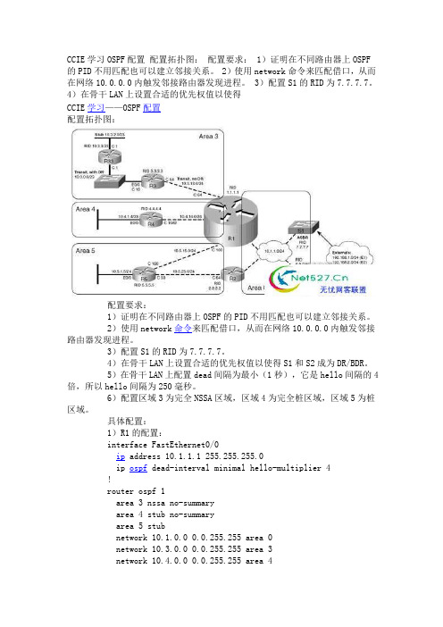
CCIE学习OSPF配置配置拓扑图:配置要求: 1)证明在不同路由器上OSPF的PID不用匹配也可以建立邻接关系。
2)使用network命令来匹配借口,从而在网络10.0.0.0内触发邻接路由器发现进程。
3)配置S1的RID为7.7.7.7。
4)在骨干LAN上设置合适的优先权值以使得CCIE学习——OSPF配置配置拓扑图:配置要求:1)证明在不同路由器上OSPF的PID不用匹配也可以建立邻接关系。
2)使用network命令来匹配借口,从而在网络10.0.0.0内触发邻接路由器发现进程。
3)配置S1的RID为7.7.7.7。
4)在骨干LAN上设置合适的优先权值以使得S1和S2成为DR/BDR。
5)在骨干LAN上配置dead间隔为最小(1秒),它是hello间隔的4倍,所以hello间隔为250毫秒。
6)配置区域3为完全NSSA区域,区域4为完全桩区域,区域5为桩区域。
具体配置:1)R1的配置:interface FastEthernet0/0ip address 10.1.1.1 255.255.255.0ip ospf dead-interval minimal hello-multiplier 4!router ospf 1area 3 nssa no-summaryarea 4 stub no-summaryarea 5 stubnetwork 10.1.0.0 0.0.255.255 area 0network 10.3.0.0 0.0.255.255 area 3network 10.4.0.0 0.0.255.255 area 4network 10.5.0.0 0.0.255.255 area 52)R2的配置:interface FastEthernet0/0ip address 10.1.1.2 255.255.255.0ip ospf dead-interval minimal hello-multiplier 4!router ospf 2area 5 stubnetwork 10.1.0.0 0.0.255.255 area 0network 10.5.25.2 0.0.0.0 area 53)R3的配置:router ospf 1area 3 nssa no-summarynetwork 10.0.0.0 0.255.255.255 area 34)R4的配置:router ospf 1area 4 stub no-summarynetwork 10.0.0.0 0.255.255.255 area 45)S1的配置:interface Vlan1ip address 10.1.1.3 255.255.255.0ip ospf dead-interval minimal hello-multiplier 4ip ospf priority 255!router ospf 1router-id 7.7.7.7network 10.1.0.0 0.0.255.255 area 06)S2的配置:interface Vlan1ip address 10.1.1.4 255.255.255.0ip ospf dead-interval minimal hello-multiplier 4ip ospf priority 254!router ospf 1network 10.0.0.0 0.255.255.255 area 0●OSPF的开销以及怎样重启OSPF进程IOS确定OSPF接口开销的方法:1)使用neighbor neighbor cost value命令对每台邻接路由器设置开销(对于允许使用neighbor命令的网络类型)。


OSPF实验及解析:实现OSPF网络实验报告一、实验名称:实现OSPF网络二、实验条件:1、配置路由器运行OSPF协议。
2、拓扑图如(三)所示。
3、要求192.168.1.0/24、192.168.2.0/24为area 1配置为完全末梢区域;192.168.3.0/24为area 0;192.168.4.0/24、192.168.5.0为area 2,配置为NSSA 区域。
路由器D的F0/1端口的辅助IP地址和路由器E运行RIP-V2。
实现OSPF区域的路由器可以和RIP路由器互相学习到网络路径。
三、实验拓扑实现OSPF网络.jpg四、实验步骤及操作:1、路由器A的配置:RouterA(config)#int loopback 0RouterA(config-if)#ip add 172.16.0.1 255.255.255.255 RouterA(config-if)#exitRouterA(config)#int f0/0RouterA(config-if)#ip add 192.168.1.1 255.255.255.0 RouterA(config-if)#no shutRouterA(config-if)#exitRouterA(config)#int f0/1RouterA(config-if)#ip add 192.168.2.1 255.255.255.0 RouterA(config-if)#no shutRouterA(config-if)#exitRouterA(config)#router ospf 10RouterA(config-router)#network 192.168.1.0 0.0.0.255 area 1 RouterA(config-router)#network 192.168.2.0 0.0.0.255 area 1 RouterA(config-router)#area 1 stubRouterA#show ip ospf databaseRouterA#show ip ospf border-router2、路由器B的配置:RouterB(config)#int loopback 0RouterB(config-if)#ip add 172.16.0.2 255.255.255.255 RouterB(config-if)#exitRouterB(config)#int f0/0RouterB(config-if)#ip add 192.168.2.2 255.255.255.0 RouterB(config-if)#no shutRouterB(config-if)#exitRouterB(config)#int f0/1RouterB(config-if)#ip add 192.168.3.1 255.255.255.0 RouterB(config-if)#no shutRouterB(config-if)#exitRouterB(config)#router ospf 10RouterB(config-router)#network 192.168.2.0 0.0.0.255 area 1 RouterB(config-router)#network 192.168.3.0 0.0.0.255 area 0 RouterB(config-router)#area 1 stub no-summary注:设置某区域为完全末梢区域的条件:1、设置内部路由器的区域为末梢区域2、在区域边界路有器上设置该区域为末梢区域且不进行路由汇总3、路由器C的配置:RouterC(config)#int loopback 0RouterC(config-if)#ip add 172.16.0.3 255.255.255.255 RouterC(config-if)#exitRouterC(config)#int f0/0RouterC(config-if)#ip add 192.168.3.2 255.255.255.0RouterC(config-if)#no shutRouterC(config-if)#exitRouterC(config)#int f0/1RouterC(config-if)#ip add 192.168.4.1 255.255.255.0RouterC(config-if)#no shutRouterC(config-if)#exitRouterC(config)#router ospf 10RouterC(config-router)#network 192.168.3.0 0.0.0.255 area 0 RouterC(config-router)#network 192.168.4.0 0.0.0.255 area 2 RouterC(config-router)#area 2 nssa no-summary4、路由器D的配置:RouterD(config)#int loopback 0RouterD(config-if)#ip add 172.16.0.4 255.255.255.255 RouterD(config-if)#exitRouterD(config)#int f0/0RouterD(config-if)#ip add 192.168.4.2 255.255.255.0RouterD(config-if)#no shutRouterD(config-if)#exitRouterD(config)#int f0/1RouterD(config-if)#ip add 192.168.5.1 255.255.255.0RouterD(config-if)#ip add 192.168.6.1 255.255.255.0 secondary RouterD(config-if)#no shutRouterD(config-if)#exitRouterD(config)#router ospf 10RouterD(config-router)#network 192.168.4.0 0.0.0.255 area 2 RouterD(config-router)#network 192.168.5.0 0.0.0.255 area 2 RouterD(config-router)#area 2 nssaRouterD(config-router)#redistribute rip metric 2 metric-type 1 RouterD(config-if)#exitRouterD(config)#router ripRouterD(config-router)#version 2RouterD(config-router)#network 192.168.6.0RouterD(config-router)#redistribute ospf 10 metric 25、路由器E的配置:RouterE(config)#int f0/0RouterE(config-if)#ip add 192.168.6.2 255.255.255.0RouterE(config-if)#no shutRouterE(config-if)#exitRouterE(config)#int f0/1RouterE(config-if)#ip add 192.168.7.1 255.255.255.0RouterE(config-if)#exitRouterE(config)#router ripRouterE(config-router)#version 2RouterE(config-router)#network 192.168.6.0RouterE(config-router)#network 192.168.7.0注:设置某区域为非完全末梢区域的条件:1、设置内部路由器的区域为非完全末梢区域2、在区域边界路有器上设置该区域为非完全末梢区域且不进行路由汇总6、PC工作站的设置:Pc1的设置:IP=192.168.1.10 Netmask=255.255.255.0Pc2的设置:IP=192.168.7.10 Netmask=255.255.255.0五、实验结果及分析在pc1上:Ping+192.168.7.10(通讯正常)在pc2上:Ping+192.168.1.10(通讯正常)由此证明配置成功注一:各Lsa的查看命令1、查看数据库中的所有路由器的Lsa的命令:show ip ospf database router2、查看数据库中的网络Lsa的命令:show ip ospf database network3、查看数据库中的网络汇总Lsa的命令:show ip ospf database summary4、查看数据库中的ASBR汇总Lsa的命令:show ip ospf database asbr-summary5、查看数据库中的自主系统外部Lsa的命令:show ip ospf database external6、查看数据库中的Nssa外部Lsa的命令:show ip ospf database nssa-external【实验环境】BENET公司总部位于北京,在上海和广州拥有分公司,现希望把三个地方的办公网络用OSPF连接起来,希望你为他们实现这个办公网络的搭建!【实验目的】按照现有拓扑图的规划,配置多区域的OSPF在他的上面配置末梢区域(Stub Area)和完全末梢区域(Totally Stublly Area)以及知道为什么要换分多区域的原因?【实验拓扑】【实验步骤】网络拓扑图的具体布线:Router1 S0/0 <----> Router2 S0/0Router2 S1/0 <----> Router3 S0/0Router3 E1/0 <----> Router4 E0/0第一步:配置路由器的回环地址和接口的IP地址;(1) 、配置Router1的回环地址和接口的IP地址;(2)、配置Router2的回环地址和接口的IP地址;(注意:在Router2上配置回环地址是根据情况而定的;Router2是属于Area2是属于骨干区域,但同时它也是一个ABR路由器;所以要配置两个接口的IP地址;因为R2是区域边界系统路由器(ABR)所以在它上面要配置两个接口的IP地址)!(3)、配置Router3的回环地址和接口的IP地址(他和Router2一样是一个ABR路由器又是Area0所以要配置两个接口的IP地址;而回环地址就在这里不在做具体的介绍了;因为R3是区域边界路由器(ABR)所以在它上面要配置两个接口的IP地址)(4)、配置Router4的回环地址和接口的IP地址;(他和Router2一样是一个ABR路由器又是Area0所以要配置两个接口的IP地址;而回环地址就在这里不在做具体的介绍了)第二步:启动OSPF的进程,并配置他们的区域末梢区域(Stub Area)和完全末梢区域(Totally Stubby Area)(1)、在Router1上配置OSPF进程以及宣告他所在的末梢区域(Stub Area)(注意:宣告OSPF的进程和宣告RIP的进程的配置是不一样的,在配置OSPF时他的进程号时本地路由器的进程号,他是来标识一台路由器的多个OSPF的进程的;)末梢区域(Stub Area )他是一个不允许自治系统外部LSA通告在其内进行泛洪的区域。

《CCNP》课程标准适用专业:计算机网络专业学制:三年制教学时数:120学时学分:6学分1.课程性质与作用课程类型:专业核心课程CCNP(Cisco Certified Network Professional)的全称是思科认证资深网络工程师。
CCNP 的学习是面向已经学完CCNA的课程并对网络技术具有一定基础,有志于成为高级网络工程师的学员。
CCNP具有使用复杂协议和技术来安装、配置、操作网络,并具备诊断及排错的能力。
凭借对知识的理解通过CCNP考试的人员是真正的网络专家(Professional),具有CCNP技术能力的网络人才被认为是网络的精英,各大公司争相聘用。
CCNP培训课程体系继续沿用CCNA课程的学期制课程,课程包括Advanced Routing、Remote Access,、Multilayer Switching、Internetworking Troubleshooting。
通过学习,学员能够深入的学习路由、交换和广域网等技术,具备安装、配置和维护大型的、复杂的多协议网络的能力,并掌握排除各种网络故障的能力。
2.课程设计2.1设计理念按照“岗位、证书与课程”三维一体的教学模式来设计课程,全面涵盖CCNP课程体系的重点知识、技能。
基于工作过程开发课程,以行动导向进行教学设计,以学生为主体,以实训为手段,设计出理论学习与技能掌握相融合的课程内容体系。
2.2设计思路1. 根据实验项目为工作任务,逐级完成的所需课程难点、重点。
本课程设计理念是以职业能力培养为重点,以就业为导向,培养学生具备职业市场所需的职业能力,生涯发展所需的能力和终身学习的能力。
2.采用“基于工作过程的项目导向、任务驱动教学模式”,以项目化教学来组织课程内容,在课程内容的选择中,以项目开发及其工作过程为背景,紧密围绕项目为载体,通过情境学习与训练,实施理论与实践相结合的教学,使学生达到熟能生巧的目的。
3.根据工作任务完成的需要、高职院校学习者的学习特点和职业能力形成的规律,按照“学习证书与职业资格证书嵌入式”的设计要求确定课程的知识、技能等内容。
CCNP认证简介CCNP证书表明拥有针对中型到大型企业网络的局域网和广域网的组网能力(路由和交换技术),能够对企业局域网和广域网进行规划、实现和检查排错。
CCNP工程师能够协同安全、语音、无线工程师共同实现企业多业务网络的构建。
CCNP认证由三门标准课程(路由、交换、排错)组成。
CCNP认证必备条件必须具备CCNA证书。
CCNP认证考试和培训课程(3门课程)(1)考试号:642-902 ROUTE课程:Implementing Cisco IP Routing (路由) v1.0(2)考试号:642-813 SWITCH课程:Implementing Cisco IP Switched Networks (交换) v1.0(3)考试号:642-832 TSHOOT课程:Troubleshooting and Maintaining CiscoIP Networks (排错) v1.0CCNP重认证CCNP证书的有效期为三年,在过期之前通过任何一门642系列(CCNP/CCIP/CCSP/CCVP等)的考试或者任何方向的CCIE笔试,证书有效期将自动延期三年。
CCNP培训课程介绍(1)路由V1.0 课程课时:8天程度:中级课程描述《路由V1.0 》课程主要针对已经具备相当于思科CCNA网络技术基础并准备在高级路由技术方面进一步提高的学员,该课程将学习使用各种路由协议规划、配置和校验企业局域网和广域网。
课程目标1.针对企业网络进行各种路由协议的规划、配置、校验和优化。
2.掌握EIGRP路由协议的原理与大型网络部署和实现。
3.掌握OSPF路由协议的原理与大型网络部署和实现。
4.掌握EIGRP路由协议的原理与大型网络部署和实现。
5.掌握多路由协议环境的重分发、路由过滤与选路控制。
6.评估常见的网络性能问题,使用三层选路控制工具控制流量转发路径。
7.使用BGP路由协议实现企业网络到运营商网络的连接。
课程内容1.规划路由服务2.实现EIGRP方案3.实现OSPF可扩展、多区域方案4.实现路由重分发5.实现路由选路控制6.连接企业网络到运营商网络(2)交换V1.0 课程课时:5天程度:中级课程描述:《交换V1.0 》课程主要针对已经具备相当于思科CCNA网络技术基础并准备在高级交换技术方面进一步提高的学员,该课程将学习使用思科园区网企业体系架构模型,规划、配置、校验和实现企业园区网的综合交换方案,包括实现企业园区网VLAN、WLAN、VOICE、VIDEO等业务流量的安全集成。
OSPF 基本配置实验要求1:如图所示配置OSPF路由协议2:区域0、1、2属于A公司,红色区域代表B公司,现在A公司把B公司收购,你要保证A公司和B公司正常通信(有二种办法,让领导任选一种)3:黄色区域中的R3和R5两台设备为公司机密数据所在,要加强安全性(二种办法,让领导任选一种)4:公司B路由条目太多,总公司希望管理员在减少路由表的前提下,不影响其它通信5:为了加强中央集权,总公司规定所有上公网的流量都通过R1出去,有利于监督和控制一:OSPF路由协议R1(config)#router ospf 110 //进程号可以自己定义R1(config-router)#router-id 1.1.1.1 //推荐手动配置router-id R1(config-router)#network 1.1.1.1 0.0.0.0 area 0R1(config-router)#network 12.1.1.0 0.0.0.255 area 0R1(config-router)#network 13.1.1.0 0.0.0.255 area 0R2(config)#router ospf 110R2(config-router)#router-id 2.2.2.2R2(config-router)#network 2.2.2.2 0.0.0.0 area 0R2(config-router)#network 12.1.1.0 0.0.0.255 area 0R2(config-router)#network 24.1.1.0 0.0.0.255 area 1R3(config)#router ospf 110R3(config-router)#router-id 3.3.3.3R3(config-router)#network 3.3.3.3 0.0.0.0 area 0R3(config-router)#network 13.1.1.0 0.0.0.255 area 0R3(config-router)#network 35.1.1.0 0.0.0.255 area 2R4(config)#router ospf 110R4(config-router)#router-id 4.4.4.4R4(config-router)#network 4.4.4.4 0.0.0.0 area 1R4(config-router)#network 24.1.1.0 0.0.0.255 area 1 R4(config-router)#network 46.1.1.0 0.0.0.255 area 0R5(config)#router ospf 110R5(config-router)#router-id 5.5.5.5R5(config-router)#network 5.5.5.5 0.0.0.0 area 2R5(config-router)#network 35.1.1.0 0.0.0.255 area 2R6(config)#router ospf 110R6(config-router)#router-id 6.6.6.6R6(config-router)#network 46.1.1.0 0.0.0.255 area 0 R6(config-router)#network 6.6.0.0 0.0.0.255 area 0 R6(config-router)#network 6.6.1.0 0.0.0.255 area 0 R6(config-router)#network 6.6.2.0 0.0.0.255 area 0 R6(config-router)#network 6.6.3.0 0.0.0.255 area 0二:不连续区域的配置1:隧道R2(config)#interface tunnel 0R2(config-if)#tunnel source 24.1.1.2 //隧道源开始的地址R2(config-if)#tunnel destination 24.1.1.4 //隧道目标地址R2(config-if)#ip add 192.168.1.1 255.255.255.0 //给隧道的地址R2(config-if)#ip ospf 110 area 0 //把隧道宣告进区域0R4(config)#interface tunnel 0R4(config-if)#tunnel source 24.1.1.4R4(config-if)#tunnel destination 24.1.1.2R4(config-if)#ip add 192.168.1.2 255.255.255.0R4(config-if)#ip ospf 110 area 02:虚链路R2(config)#router ospf 110R2(config-router)#area 1 virtual-link 4.4.4.4//注意红色标记R4(config)#router ospf 110R4(config-router)#area 1 virtual-link 2.2.2.2三:加密1:明文R3(config-if)#interface s0/0R3(config-if)#ip ospf authenticationR3(config-if)#ip ospf authentication-key 1234R5(config)#interface s0/1R5(config-if)#ip ospf authenticationR5(config-if)#ip ospf authentication-key 12342:密文R3(config)#interface s0/0R3(config-if)#ip ospf authentication message-digestR3(config-if)#ip ospf message-digest-key 1 md5 1234R5(config)#interface s0/1R5(config-if)#ip ospf authenticatio message-digestR5(config-if)#ip ospf message-digest-key 1 md5 1234四:汇总R6(config)#interface loopback 0R6(config-if)#ip ospf network point-to-point //改网络类型R3(config)#router ospf 110R3(config-router)#area 0 range 6.6.0.0 255.255.252.0五:下发默认路由R1(config)#ip route 0.0.0.0 0.0.0.0 null 0 //写一条默认路由R1(config)#router ospf 110R1(config-router)#default-information originate always。
CCNP 路由笔一OSPF 篇:OSPF EIGRP 都是用 4 个逻辑分支 1 发现邻居(发送 hello 报文)2 建立邻居表( two way )3 建立拓扑表4 建立路由表(选择最佳路由)流程为down -nit- two way(建立邻居成功 DR BDR选举完成)-exstat (交换之前会选出主从关系确定谁先发送数据) -exchange (交换 DB 过程) loadiing (交换 lsu ) full (完成整个数据交换 ospf 真个过程建立完成)。
基础知识1. ABR (至少有一个接口与另外两个 OSPF 区域相连)骨干路由器(至少有一个接口在 AREA 0 区域内)内部路由器(所有接口都再这个区域内)指定路由器DR (在交换数据链路LSA时不是每个路由器都相互转发而是通过DR/BDR 进行 2. DRother 向 DR,BDR 发送 DD,LSA request 或者 LSA UPdate 时目标地址是 AllDRouter(224.0.0.6); 或者理解为: DR 侦听 224.0.0.6DR,BDR 向 DRother 发送 DD,LSA Request 或者 LSA Update 时目标地址是AllSPFRouter(224.0.0.5); 或者理解为: DRother 侦听 224.0.0.5并且所有的 DROTHER 与 DR 只会形成 TWOWAY 邻居关系但是不会形成 full只有 DR 或 BDR 出现故障才回重新选举,即使加进来的优先级或者 RID 再打也不会重新选举,如果 DR 出现故障那么 BDR 接替,如果 BDR 出现故障重新选举 BDR,DR 保持不变LSA^9誓通名称1SffiS ISA■斑茁踊庄罢都创冊1芸LSA.壬亍充逹站的曲个寰N材疋目己在国芳斎串器中,毎丁艺减的LSDBBLgg-Tl S ISA EJEiiiT当IGRS田畚昭罔口和所宵損□的IP芯址.1貝LSA込嘉于确还裳节弼燈2 I两殆LSA毎卞中精駅虽一亍・田子屠中阳D復创It・H还了子购及厦摄SJ霞孕网的JS田墓接口3強第汇总LSA 1 ®IO 2 LSA .戡週吿期舅—亍区増.它■出了汹撻居K昭fiW f子卿)和幵情.归不暫塞柘卄戳据4ASBR U LSA畫魁于3 LSA.只屋谢害一翹銅于前柱ASBR的主机匪由5AS外圈LSA S AS6R 用于搭逹豪注心OSPF胸3外由6迟昵员商空LSA)S»?9 MOSPF SAW. Cisco IOS 不贡持亘7NSSA 外茁LSA冥幅于5笑LSA” RgBNSSA^^内的ASBR包周B外那■性LSA实册匹9—1一-不Q明用ft運崔LWA”朝万诞睾棗护展03P餐洌如”内直梅胡RLS遼■工螺0改了1QS LSA 地址ABR会有很多1类LSA,每个区域的LSA都会在ABR中列出'。
ospf配置实验报告OSPF 配置实验报告一、实验目的本次实验的主要目的是深入理解和掌握开放式最短路径优先(Open Shortest Path First,OSPF)协议的工作原理,并通过实际配置和测试,熟练掌握 OSPF 在网络中的应用。
二、实验环境1、网络拓扑结构本次实验使用了如下图所示的网络拓扑结构:此处插入网络拓扑图该拓扑包括了三台路由器 R1、R2 和 R3,以及若干台连接在路由器上的终端设备。
2、设备及软件使用的路由器型号为_____,配置终端软件为_____。
三、实验原理OSPF 是一种链路状态路由协议,它通过收集网络中各个路由器的链路状态信息,构建出整个网络的拓扑结构,并基于此计算出最短路径。
OSPF 工作过程主要包括以下几个步骤:1、发现邻居:路由器通过发送Hello 报文来发现和维护邻居关系。
2、交换链路状态信息:邻居路由器之间交换链路状态通告(LSA),以描述网络拓扑和链路状态。
3、计算路由:根据收到的 LSA,路由器使用迪杰斯特拉算法计算出到各个目的地的最短路径,并生成路由表。
四、实验步骤1、基本配置为每台路由器配置接口 IP 地址。
启用 OSPF 进程,并指定区域号。
配置路由器的 Router ID。
以 R1 为例,配置命令如下:```interface GigabitEthernet0/0ip address 19216811 2552552550interface GigabitEthernet0/1ip address 19216821 2552552550router ospf 1routerid 1111network 19216810 000255 area 0network 19216820 000255 area 0```2、配置 OSPF 区域将网络划分为不同的区域,以减少路由信息的传播范围和复杂度。
配置区域类型,如骨干区域(Area 0)和非骨干区域。
Lab 3-2 Multiple-Area OSPF with Stub Areas and Authentication Learning Objectives• Configure multiple-area OSPF on a router•Verify multiple-area behavior•Configure OSPF stub, totally stubby, and not so stubby areas• Configure OSPF authenticationTopologyScenarioYou are responsible for configuring the new network to connect your company’s Engineering, Marketing, and Accounting departments, represented by loopback interfaces on each of the three routers. The physical devices have just been installed and connected by serial cables. Configure multiple-area OSPF to allow full connectivity between all departments.R3 will also have a loopback representing a connection to another autonomous system that is not part of OSPF.This topology may appear again in future labs, so save your configuration.Step 1: AddressingSet up the physical serial interfaces on R1, R2, and R3 with IP addresses, and bring them up. Depending on which router models you have, you may need to add clock rates to the DCE end of each connection (newer equipment adds this automatically). Verify that you can ping across each serial link. Add theloopbacks shown in the diagram to each router.R1# configure terminalEnter configuration commands, one per line. End with CNTL/Z.R1(config)# interface loopback 1R1(config-if)# ip address 10.1.1.1 255.255.255.0R1(config-if)# interface serial 0/0/0R1(config-if)# ip address 10.1.12.1 255.255.255.0R1(config-if)# clockrate 64000R1(config-if)# no shutdownR2# configure terminalEnter configuration commands, one per line. End with CNTL/Z.R2(config)# interface loopback 2R2(config-if)# ip address 10.1.2.1 255.255.255.0R2(config-if)# interface serial 0/0/0R2(config-if)# ip address 10.1.12.2 255.255.255.0R2(config-if)# no shutdownR2(config-if)# interface serial 0/0/1R2(config-if)# ip address 10.1.23.2 255.255.255.0R2(config-if)# clockrate 64000R2(config-if)# no shutdownR3# configure terminalEnter configuration commands, one per line. End with CNTL/Z.R3(config)# interface loopback 3R3(config-if)# ip address 10.1.3.1 255.255.255.0R3(config-if)# interface loopback 20R3(config-if)# ip address 172.20.200.1 255.255.255.0R3(config-if)# interface serial 0/0/1R3(config-if)# ip address 10.1.23.1 255.255.255.0R3(config-if)# no shutdownStep 2: Adding Interfaces into OSPFCreate OSPF process 1 on all three routers. Configure the subnet of the serial link between R1 and R2 to be in OSPF area 0 using the network command.Add loopback 1 on R1 and loopback 2 on R2 into OSPF area 0. Verify that you can see OSPF neighbors in the show ip ospf neighbors output on bothrouters and that they can see each other’s loopback with the show ip route command. Change the network type on the loopback interfaces so that they are advertised with the correct subnet.R1(config)# router ospf 1R1(config-router)# network 10.1.12.0 0.0.0.255 area 0R1(config-router)# network 10.1.1.0 0.0.0.255 area 0R1(config-router)# interface loopback 1R1(config-if)# ip ospf network point-to-pointR2(config)# router ospf 1R2(config-router)# network 10.1.12.0 0.0.0.255 area 0R2(config-router)# network 10.1.2.0 0.0.0.255 area 0R2(config-router)# interface loopback 2R2(config-if)# ip ospf network point-to-pointR1# show ip ospf neighborNeighbor ID Pri State Dead Time Address Interface 10.1.2.1 0 FULL/ - 00:00:38 10.1.12.2 Serial0/0/0 R1# show ip routeCodes: C - connected, S - static, R - RIP, M - mobile, B - BGPD - EIGRP, EX - EIGRP external, O - OSPF, IA - OSPF inter areaN1 - OSPF NSSA external type 1, N2 - OSPF NSSA external type 2E1 - OSPF external type 1, E2 - OSPF external type 2i - IS-IS, su - IS-IS summary, L1 - IS-IS level-1, L2 - IS-IS level-2ia - IS-IS inter area, * - candidate default, U - per-user static route o - ODR, P - periodic downloaded static routeGateway of last resort is not set10.0.0.0/24 is subnetted, 3 subnetsC 10.1.12.0 is directly connected, Serial0/0/0O 10.1.2.0 [110/65] via 10.1.12.2, 00:00:10, Serial0/0/0C 10.1.1.0 is directly connected, Loopback1R2# show ip ospf neighborNeighbor ID Pri State Dead Time Address Interface 10.1.1.1 0 FULL/ - 00:00:35 10.1.12.1 Serial0/0/0 R2# show ip routeCodes: C - connected, S - static, R - RIP, M - mobile, B - BGPD - EIGRP, EX - EIGRP external, O - OSPF, IA - OSPF inter areaN1 - OSPF NSSA external type 1, N2 - OSPF NSSA external type 2E1 - OSPF external type 1, E2 - OSPF external type 2i - IS-IS, su - IS-IS summary, L1 - IS-IS level-1, L2 - IS-IS level-2ia - IS-IS inter area, * - candidate default, U - per-user static route o - ODR, P - periodic downloaded static routeGateway of last resort is not set10.0.0.0/24 is subnetted, 4 subnetsC 10.1.12.0 is directly connected, Serial0/0/0C 10.1.2.0 is directly connected, Loopback2O 10.1.1.0 [110/65] via 10.1.12.1, 00:00:30, Serial0/0/0C 10.1.23.0 is directly connected, Serial0/0/1Add the subnet between R2 and R3 into OSPF area 23 using the network command. Add loopback 3 on R3 into area 23. Verify that this neighbor relationship comes up using the show ip ospf neighbors command.R2(config)# router ospf 1R2(config-router)# network 10.1.23.0 0.0.0.255 area 23R3(config)# router ospf 1R3(config-router)# network 10.1.23.0 0.0.0.255 area 23R3(config-router)# network 10.1.3.0 0.0.0.255 area 23R3(config-router)# interface loopback 3R3(config-if)# ip ospf network point-to-pointR2# show ip ospf neighborNeighbor ID Pri State Dead Time Address Interface10.1.1.1 0 FULL/ - 00:00:36 10.1.12.1 Serial0/0/0172.20.200.1 0 FULL/ - 00:00:36 10.1.23.3 Serial0/0/1 If you look at the output of the show ip route command on R1, you see a route to R3’s loopback. Notice that it comes in as an inter-area route.R1# show ip routeCodes: C - connected, S - static, R - RIP, M - mobile, B - BGPD - EIGRP, EX - EIGRP external, O - OSPF, IA - OSPF inter areaN1 - OSPF NSSA external type 1, N2 - OSPF NSSA external type 2E1 - OSPF external type 1, E2 - OSPF external type 2i - IS-IS, su - IS-IS summary, L1 - IS-IS level-1, L2 - IS-IS level-2ia - IS-IS inter area, * - candidate default, U - per-user static route o - ODR, P - periodic downloaded static routeGateway of last resort is not set10.0.0.0/24 is subnetted, 5 subnetsC 10.1.12.0 is directly connected, Serial0/0/0O IA 10.1.3.0 [110/129] via 10.1.12.2, 00:00:28, Serial0/0/0O 10.1.2.0 [110/65] via 10.1.12.2, 00:01:38, Serial0/0/0C 10.1.1.0 is directly connected, Loopback1O IA 10.1.23.0 [110/128] via 10.1.12.2, 00:01:38, Serial0/0/0R2 has no inter-area routes, because R2 is in both areas; it is an ABR, or area border router.R2# show ip routeCodes: C - connected, S - static, R - RIP, M - mobile, B - BGPD - EIGRP, EX - EIGRP external, O - OSPF, IA - OSPF inter areaN1 - OSPF NSSA external type 1, N2 - OSPF NSSA external type 2E1 - OSPF external type 1, E2 - OSPF external type 2i - IS-IS, su - IS-IS summary, L1 - IS-IS level-1, L2 - IS-IS level-2ia - IS-IS inter area, * - candidate default, U - per-user static route o - ODR, P - periodic downloaded static routeGateway of last resort is not set10.0.0.0/24 is subnetted, 5 subnetsC 10.1.12.0 is directly connected, Serial0/0/0O 10.1.3.0 [110/65] via 10.1.23.3, 00:00:50, Serial0/0/1C 10.1.2.0 is directly connected, Loopback2O 10.1.1.0 [110/65] via 10.1.12.1, 00:02:00, Serial0/0/0C 10.1.23.0 is directly connected, Serial0/0/1Verify that you can ping all interfaces from any router, with the exception ofloopback 20 on R3, which has not yet been configured as part of OSPF.Step 3: Stub AreasUnder the OSPF process on R2 and R3, make area 23 the stub area using the area area stub command. The adjacency between the two routers may godown during the transition period, but it should come back up afterwards.Confirm that it comes up by using the show ip ospf neighbors command.R2(config)# router ospf 1R2(config-router)# area 23 stubR3(config)# router ospf 1R3(config-router)# area 23 stubR2# show ip ospf neighborNeighbor ID Pri State Dead Time Address Interface 10.1.1.1 0 FULL/ - 00:00:36 10.1.12.1 Serial0/0/0 172.20.200.1 0 FULL/ - 00:00:36 10.1.23.3 Serial0/0/1R3# show ip ospf neighborNeighbor ID Pri State Dead Time Address Interface 10.1.2.1 0 FULL/ - 00:00:31 10.1.23.2 Serial0/0/1 Using the show ip route command, you can see that R3 now has a default route pointing toward R2. A stub area does not get any external routes. A stub area receives a default route and OSPF inter area routes.R3# show ip routeCodes: C - connected, S - static, R - RIP, M - mobile, B - BGPD - EIGRP, EX - EIGRP external, O - OSPF, IA - OSPF inter areaN1 - OSPF NSSA external type 1, N2 - OSPF NSSA external type 2E1 - OSPF external type 1, E2 - OSPF external type 2i - IS-IS, su - IS-IS summary, L1 - IS-IS level-1, L2 - IS-IS level-2ia - IS-IS inter area, * - candidate default, U - per-user static route o - ODR, P - periodic downloaded static routeGateway of last resort is 10.1.23.2 to network 0.0.0.0172.20.0.0/24 is subnetted, 1 subnetsC 172.20.200.0 is directly connected, Loopback2010.0.0.0/24 is subnetted, 5 subnetsO IA 10.1.12.0 [110/128] via 10.1.23.2, 00:00:56, Serial0/0/1C 10.1.3.0 is directly connected, Loopback3O IA 10.1.2.0 [110/65] via 10.1.23.2, 00:00:56, Serial0/0/1O IA 10.1.1.0 [110/129] via 10.1.23.2, 00:00:56, Serial0/0/1C 10.1.23.0 is directly connected, Serial0/0/1O*IA 0.0.0.0/0 [110/65] via 10.1.23.2, 00:00:56, Serial0/0/1Take a look at the output of the show ip ospf command to see what type each area is.R2# show ip ospfRouting Process "ospf 1" with ID 10.1.2.1Supports only single TOS(TOS0) routesSupports opaque LSASupports Link-local Signaling (LLS)Supports area transit capabilityIt is an area border routerInitial SPF schedule delay 5000 msecsMinimum hold time between two consecutive SPFs 10000 msecsMaximum wait time between two consecutive SPFs 10000 msecsIncremental-SPF disabledMinimum LSA interval 5 secsMinimum LSA arrival 1000 msecsLSA group pacing timer 240 secsInterface flood pacing timer 33 msecsRetransmission pacing timer 66 msecsNumber of external LSA 0. Checksum Sum 0x000000Number of opaque AS LSA 0. Checksum Sum 0x000000Number of DCbitless external and opaque AS LSA 0Number of DoNotAge external and opaque AS LSA 0Number of areas in this router is 2. 1 normal 1 stub 0 nssaNumber of areas transit capable is 0External flood list length 0Area BACKBONE(0)Number of interfaces in this area is 2Area has no authenticationSPF algorithm last executed 00:02:11.680 agoSPF algorithm executed 5 timesArea ranges areNumber of LSA 4. Checksum Sum 0x01A85ANumber of opaque link LSA 0. Checksum Sum 0x000000Number of DCbitless LSA 0Number of indication LSA 0Number of DoNotAge LSA 0Flood list length 0Area 23Number of interfaces in this area is 1It is a stub areagenerates stub default route with cost 1Area has no authenticationSPF algorithm last executed 00:01:38.276 agoSPF algorithm executed 8 timesArea ranges areNumber of LSA 6. Checksum Sum 0x027269Number of opaque link LSA 0. Checksum Sum 0x000000Number of DCbitless LSA 0Number of indication LSA 0Number of DoNotAge LSA 0Flood list length 0What advantages would be gained by having a router get a default route rather than a more specific route?Why do all routers in a stub area need to know that that area is a stub?Step 4: Totally Stubby AreasA modified version of a stubby area is a totally stubby area. A totally stubbyarea ABR only allows in a single, default route from the backbone. To configure this, you only need to change a command at the ABR, in our case, R2. Under the router OSPF process, enter the area 23 stub no-summary command. This replaces the existing stub command for area 23. no-summary tells the router that this area will not receive summary (inter-area) routes.To see how this works, first issue the show ip route command on R3. Notice the inter-area routes in addition to the default route generated by R2. Also, look at show ip ospf database on R2 to see what LSAs are in its OSPF database. R3# show ip routeCodes: C - connected, S - static, R - RIP, M - mobile, B - BGPD - EIGRP, EX - EIGRP external, O - OSPF, IA - OSPF inter areaN1 - OSPF NSSA external type 1, N2 - OSPF NSSA external type 2E1 - OSPF external type 1, E2 - OSPF external type 2i - IS-IS, su - IS-IS summary, L1 - IS-IS level-1, L2 - IS-IS level-2ia - IS-IS inter area, * - candidate default, U - per-user static route o - ODR, P - periodic downloaded static routeGateway of last resort is 10.1.23.2 to network 0.0.0.0172.20.0.0/24 is subnetted, 1 subnetsC 172.20.200.0 is directly connected, Loopback2010.0.0.0/24 is subnetted, 5 subnetsO IA 10.1.12.0 [110/128] via 10.1.23.2, 00:00:56, Serial0/0/1C 10.1.3.0 is directly connected, Loopback3O IA 10.1.2.0 [110/65] via 10.1.23.2, 00:00:56, Serial0/0/1O IA 10.1.1.0 [110/129] via 10.1.23.2, 00:00:56, Serial0/0/1C 10.1.23.0 is directly connected, Serial0/0/1O*IA 0.0.0.0/0 [110/65] via 10.1.23.2, 00:00:56, Serial0/0/1R2# show ip ospf databaseOSPF Router with ID (10.1.2.1) (Process ID 1)Router Link States (Area 0)Link ID ADV Router Age Seq# Checksum Link count10.1.1.1 10.1.1.1 435 0x80000004 0x0056D6 310.1.2.1 10.1.2.1 358 0x80000003 0x0057D2 3Summary Net Link States (Area 0)Link ID ADV Router Age Seq# Checksum10.1.3.0 10.1.2.1 174 0x80000001 0x00EFEF10.1.23.0 10.1.2.1 354 0x80000001 0x0009C3Router Link States (Area 23)Link ID ADV Router Age Seq# Checksum Link count10.1.2.1 10.1.2.1 188 0x80000004 0x00298C 2172.20.200.1 172.20.200.1 188 0x80000004 0x00B762 3Summary Net Link States (Area 23)Link ID ADV Router Age Seq# Checksum0.0.0.0 10.1.2.1 207 0x80000001 0x003BF410.1.1.0 10.1.2.1 209 0x80000002 0x0022C010.1.2.0 10.1.2.1 209 0x80000002 0x00948D10.1.12.0 10.1.2.1 209 0x80000002 0x009E3ANow, enter the no-summary stub command on R2 (the ABR) under the OSPF process.R2(config)# router ospf 1R2(config-router)# area 23 stub no-summaryGo back to R3 and look at show ip route again. Notice that it only has one incoming route from OSPF. Also look at the show ip ospf database output to see which routes are in area 23.R3# show ip routeCodes: C - connected, S - static, R - RIP, M - mobile, B - BGPD - EIGRP, EX - EIGRP external, O - OSPF, IA - OSPF inter areaN1 - OSPF NSSA external type 1, N2 - OSPF NSSA external type 2E1 - OSPF external type 1, E2 - OSPF external type 2i - IS-IS, su - IS-IS summary, L1 - IS-IS level-1, L2 - IS-IS level-2ia - IS-IS inter area, * - candidate default, U - per-user static route o - ODR, P - periodic downloaded static routeGateway of last resort is 10.1.23.2 to network 0.0.0.0172.20.0.0/24 is subnetted, 1 subnetsC 172.20.200.0 is directly connected, Loopback2010.0.0.0/24 is subnetted, 2 subnetsC 10.1.3.0 is directly connected, Loopback3C 10.1.23.0 is directly connected, Serial0/0/1O*IA 0.0.0.0/0 [110/65] via 10.1.23.2, 00:00:10, Serial0/0/1R2# show ip ospf databaseOSPF Router with ID (10.1.2.1) (Process ID 1)Router Link States (Area 0)Link ID ADV Router Age Seq# Checksum Link count10.1.1.1 10.1.1.1 522 0x80000004 0x0056D6 310.1.2.1 10.1.2.1 445 0x80000003 0x0057D2 3Summary Net Link States (Area 0)Link ID ADV Router Age Seq# Checksum10.1.3.0 10.1.2.1 261 0x80000001 0x00EFEF10.1.23.0 10.1.2.1 441 0x80000001 0x0009C3Router Link States (Area 23)Link ID ADV Router Age Seq# Checksum Link count10.1.2.1 10.1.2.1 275 0x80000004 0x00298C 2172.20.200.1 172.20.200.1 276 0x80000004 0x00B762 3Summary Net Link States (Area 23)Link ID ADV Router Age Seq# Checksum0.0.0.0 10.1.2.1 68 0x80000002 0x0039F5What advantages would there be in making an area totally stubby instead of a regular stub area? What are the disadvantages?Why did only the ABR need to know that the area was totally stubby rather than all routers in the area?Step 5: Not So Stubby AreasNot so stubby areas (NSSAs) are similar to regular stub areas, except that they allow routes to be redistributed from an ASBR into that area with a special LSA type, which gets converted to a normal external route at the ABR. For this lab, we will change area 23 into an NSSA. NSSAs are not compatible with stubareas, so the first thing we must do is issue a no area 23 stub command on routers R2 and R3.Next, we issue the area area nssa command on routers R2 and R3 to change area 23 to an NSSA. To generate an external route into the NSSA, use theredistribute connected subnets command on R3. This adds the previously unreachable loopback 20 into OSPF. Be sure to include the subnets keyword;otherwise, only classful networks are redistributed.R2(config)# router ospf 1R2(config-router)# no area 23 stubR2(config-router)# area 23 nssaR3(config)# router ospf 1R3(config-router)# no area 23 stubR3(config-router)# area 23 nssaR3(config-router)# redistribute connected subnetsTake a look at the output of show ip ospf on R2. Notice that area 23 is anNSSA and that R2 is performing the LSA type 7 to type 5 translation. If there are multiple ABRs to an NSSA, the ABR with the highest router ID performs the translation.R2# show ip ospfRouting Process "ospf 1" with ID 10.1.2.1Supports only single TOS(TOS0) routesSupports opaque LSASupports Link-local Signaling (LLS)Supports area transit capabilityIt is an area border and autonomous system boundary routerRedistributing External Routes from,Initial SPF schedule delay 5000 msecsMinimum hold time between two consecutive SPFs 10000 msecsMaximum wait time between two consecutive SPFs 10000 msecsIncremental-SPF disabledMinimum LSA interval 5 secsMinimum LSA arrival 1000 msecsLSA group pacing timer 240 secsInterface flood pacing timer 33 msecsRetransmission pacing timer 66 msecsNumber of external LSA 1. Checksum Sum 0x00CA2FNumber of opaque AS LSA 0. Checksum Sum 0x000000Number of DCbitless external and opaque AS LSA 0Number of DoNotAge external and opaque AS LSA 0Number of areas in this router is 2. 1 normal 0 stub 1 nssaNumber of areas transit capable is 0External flood list length 0Area BACKBONE(0)Number of interfaces in this area is 2Area has no authenticationSPF algorithm last executed 00:03:11.636 agoSPF algorithm executed 9 timesArea ranges areNumber of LSA 4. Checksum Sum 0x01AC53Number of opaque link LSA 0. Checksum Sum 0x000000Number of DCbitless LSA 0Number of indication LSA 0Number of DoNotAge LSA 0Flood list length 0Area 23Number of interfaces in this area is 1It is a NSSA areaPerform type-7/type-5 LSA translationArea has no authenticationSPF algorithm last executed 00:00:16.408 agoSPF algorithm executed 16 timesArea ranges areNumber of LSA 6. Checksum Sum 0x025498Number of opaque link LSA 0. Checksum Sum 0x000000Number of DCbitless LSA 0Number of indication LSA 0Number of DoNotAge LSA 0Flood list length 0Now look at the show ip route output on R2. Notice that the “external” route comes in as type N2 from R3. This is because it is a special NSSA external route.R2# show ip routeCodes: C - connected, S - static, R - RIP, M - mobile, B - BGPD - EIGRP, EX - EIGRP external, O - OSPF, IA - OSPF inter areaN1 - OSPF NSSA external type 1, N2 - OSPF NSSA external type 2E1 - OSPF external type 1, E2 - OSPF external type 2i - IS-IS, su - IS-IS summary, L1 - IS-IS level-1, L2 - IS-IS level-2ia - IS-IS inter area, * - candidate default, U - per-user static route o - ODR, P - periodic downloaded static routeGateway of last resort is not set172.20.0.0/24 is subnetted, 1 subnetsO N2 172.20.200.0 [110/20] via 10.1.23.3, 00:00:41, Serial0/0/110.0.0.0/24 is subnetted, 5 subnetsC 10.1.12.0 is directly connected, Serial0/0/0O 10.1.3.0 [110/65] via 10.1.23.3, 00:00:47, Serial0/0/1C 10.1.2.0 is directly connected, Loopback2O 10.1.1.0 [110/65] via 10.1.12.1, 00:03:42, Serial0/0/0C 10.1.23.0 is directly connected, Serial0/0/1Look at the show ip route output on R1. Notice that now the route is a regular E2 external route, because R2 has performed the type 7 to type 5 translation.R1# show ip routeCodes: C - connected, S - static, R - RIP, M - mobile, B - BGPD - EIGRP, EX - EIGRP external, O - OSPF, IA - OSPF inter areaN1 - OSPF NSSA external type 1, N2 - OSPF NSSA external type 2E1 - OSPF external type 1, E2 - OSPF external type 2i - IS-IS, su - IS-IS summary, L1 - IS-IS level-1, L2 - IS-IS level-2ia - IS-IS inter area, * - candidate default, U - per-user static route o - ODR, P - periodic downloaded static routeGateway of last resort is not set172.20.0.0/24 is subnetted, 1 subnetsO E2 172.20.200.0 [110/20] via 10.1.12.2, 00:01:22, Serial0/0/010.0.0.0/24 is subnetted, 5 subnetsC 10.1.12.0 is directly connected, Serial0/0/0O IA 10.1.3.0 [110/129] via 10.1.12.2, 00:02:06, Serial0/0/0O 10.1.2.0 [110/65] via 10.1.12.2, 00:04:22, Serial0/0/0C 10.1.1.0 is directly connected, Loopback1O IA 10.1.23.0 [110/128] via 10.1.12.2, 00:04:22, Serial0/0/0If you look at the show ip route output on R3, you may notice that it no longer has a default route in it, but inter-area routes are coming in.R3# show ip routeCodes: C - connected, S - static, R - RIP, M - mobile, B - BGPD - EIGRP, EX - EIGRP external, O - OSPF, IA - OSPF inter areaN1 - OSPF NSSA external type 1, N2 - OSPF NSSA external type 2E1 - OSPF external type 1, E2 - OSPF external type 2i - IS-IS, su - IS-IS summary, L1 - IS-IS level-1, L2 - IS-IS level-2ia - IS-IS inter area, * - candidate default, U - per-user static route o - ODR, P - periodic downloaded static routeGateway of last resort is not set172.20.0.0/24 is subnetted, 1 subnetsC 172.20.200.0 is directly connected, Loopback2010.0.0.0/24 is subnetted, 5 subnetsO IA 10.1.12.0 [110/128] via 10.1.23.2, 00:02:11, Serial0/0/1C 10.1.3.0 is directly connected, Loopback3O IA 10.1.2.0 [110/65] via 10.1.23.2, 00:02:11, Serial0/0/1O IA 10.1.1.0 [110/129] via 10.1.23.2, 00:02:11, Serial0/0/1C 10.1.23.0 is directly connected, Serial0/0/1We can change this by making the area a totally not so stubby area. To configure this, issue the area 23 nssa no-summary command on R2, similar to converting a stub area into a totally stubby area. Then, check the routing table on R3 and notice that the inter-area routes have been replaced by a single default route.R2(config)# router ospf 1R2(config-router)# area 23 nssa no-summaryR3# show ip routeCodes: C - connected, S - static, R - RIP, M - mobile, B - BGPD - EIGRP, EX - EIGRP external, O - OSPF, IA - OSPF inter areaN1 - OSPF NSSA external type 1, N2 - OSPF NSSA external type 2E1 - OSPF external type 1, E2 - OSPF external type 2i - IS-IS, su - IS-IS summary, L1 - IS-IS level-1, L2 - IS-IS level-2ia - IS-IS inter area, * - candidate default, U - per-user static route o - ODR, P - periodic downloaded static routeGateway of last resort is 10.1.23.2 to network 0.0.0.0172.20.0.0/24 is subnetted, 1 subnetsC 172.20.200.0 is directly connected, Loopback2010.0.0.0/24 is subnetted, 2 subnetsC 10.1.3.0 is directly connected, Loopback3C 10.1.23.0 is directly connected, Serial0/0/1O*IA 0.0.0.0/0 [110/65] via 10.1.23.2, 00:00:20, Serial0/0/1Also on R2, take a look at the show ip ospf database output to see the various LSA types.R2# show ip ospf databaseOSPF Router with ID (10.1.2.1) (Process ID 1)Router Link States (Area 0)Link ID ADV Router Age Seq# Checksum Link count10.1.1.1 10.1.1.1 944 0x80000004 0x0056D6 310.1.2.1 10.1.2.1 383 0x80000004 0x005BCB 3Summary Net Link States (Area 0)Link ID ADV Router Age Seq# Checksum10.1.3.0 10.1.2.1 242 0x80000001 0x00EFEF10.1.23.0 10.1.2.1 862 0x80000001 0x0009C3Router Link States (Area 23)Link ID ADV Router Age Seq# Checksum Link count10.1.2.1 10.1.2.1 257 0x80000007 0x00B0F7 2172.20.200.1 172.20.200.1 209 0x80000007 0x003FCD 3Summary Net Link States (Area 23)Link ID ADV Router Age Seq# Checksum0.0.0.0 10.1.2.1 34 0x80000001 0x00C265Type-7 AS External Link States (Area 23)Link ID ADV Router Age Seq# Checksum Tag172.20.200.0 172.20.200.1 200 0x80000001 0x0076FC 0Type-5 AS External Link StatesLink ID ADV Router Age Seq# Checksum Tag172.20.200.0 10.1.2.1 199 0x80000001 0x00CA2F 0Where would making an area an NSSA be useful?Step 6: OSPF Interface AuthenticationFor security purposes, you can set OSPF interfaces to use authentication. For this lab, we will configure OSPF authentication on both serial links. We willconfigure the link between R2 and R3 for plain-text authentication, and the link between R1 and R2 for MD5 authentication, which encrypts the password for stronger security. Both passwords will be cisco. We will set up all of theauthentication on a per-interface basis.To set up plain-text authentication on an interface, go to the interface command prompt and type ip ospf authentication. Next, set a password with ip ospfauthentication-key key-string. Configure this on both R2 and R3. Verify the authentication using the show ip ospf interface interface command. While configuring this, the adjacency may go down if the dead timer expires on one of the routers. The relationship comes back up once authentication is configured on both sides.R2(config)# interface serial 0/0/1R2(config-if)# ip ospf authenticationR2(config-if)# ip ospf authentication-key ciscoR3(config)# interface serial 0/0/1R3(config-if)# ip ospf authenticationR3(config-if)# ip ospf authentication-key ciscoR2# show ip ospf interface serial 0/0/1Serial0/0/1 is up, line protocol is upInternet Address 10.1.23.2/24, Area 23Process ID 1, Router ID 10.1.2.1, Network Type POINT_TO_POINT, Cost: 64Transmit Delay is 1 sec, State POINT_TO_POINT,Timer intervals configured, Hello 10, Dead 40, Wait 40, Retransmit 5oob-resync timeout 40Hello due in 00:00:09Supports Link-local Signaling (LLS)Index 1/3, flood queue length 0Next 0x0(0)/0x0(0)Last flood scan length is 1, maximum is 4Last flood scan time is 0 msec, maximum is 0 msecNeighbor Count is 1, Adjacent neighbor count is 1Adjacent with neighbor 172.20.200.1Suppress hello for 0 neighbor(s)Simple password authentication enabledThe commands are similar to set up MD5 authentication on an interface. First, use the interface-level command ip ospf authentication message-digest to set the interface authentication type. Next, use the command ip ospf message-digest-key key_number key-string. Make sure that the key number is the same on both routers. In this case, use 1 for simplicity. Verify the configuration using the show ip ospf interface interface command. While configuring this, the adjacency may go down if the dead timer expires on one of the routers. The relationship comes back up once authentication is configured on both sides.R1(config)# interface serial 0/0/0R1(config-if)# ip ospf authentication message-digestR1(config-if)# ip ospf message-digest-key 1 md5 ciscoR2(config)# interface serial 0/0/0R2(config-if)# ip ospf authentication message-digestR2(config-if)# ip ospf message-digest-key 1 md5 ciscoR1# show ip ospf interface serial 0/0/0Serial0/0/0 is up, line protocol is upInternet Address 10.1.12.1/24, Area 0Process ID 1, Router ID 10.1.1.1, Network Type POINT_TO_POINT, Cost: 64Transmit Delay is 1 sec, State POINT_TO_POINT,Timer intervals configured, Hello 10, Dead 40, Wait 40, Retransmit 5oob-resync timeout 40Hello due in 00:00:08。