
潜水泵操作说明书
- 格式:pdf
- 大小:7.24 MB
- 文档页数:12
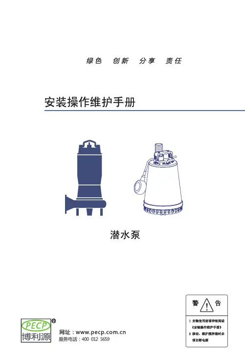

潜水排污泵、给水泵安装、使用、维护说明书前言为保证设备正常运行和人身安全,在安装运行前应认真阅读本说明书。
本设备应由技术熟练的人员进行安装和操作运行,制造厂不承担由非专业人员参与而发生事故和责任。
如疑问,请即与本公司驻当地办事处联系。
一、主要用途和使用范围WQ、QXG、AS、AV系列潜水排污泵、潜水给水泵采用了国外多项先进技术,结构紧凑,使用维护方便。
其大通道水力部件设计和抗堵塞撕裂机构使水泵具有优良的过流性能,较高的工作可靠性,有利于实现自动化。
它广泛应用于市政工程、工业、商业、医院、宾馆、住宅区的污水排放,也适用于采油、农田灌溉等。
产品执行JB/T5118-2001《污水污物潜水电泵》标准。
使用条件:●输送介质最高温度应不超过40°C;●输送介质PH值为4~10;●输送介质中的固相物的容积比在2%以下;●输送介质的运动粘度为7╳10-7~23╳10-6m2/s;●输送介质介质密度应小于1.2╳103kg/m3;●可通过固体颗粒直径:φ25~φ180;●最大潜水深度:10m;●每二次启动间隔时间不小于10分钟。
二、系统说明WQ、AV、AS系列产品由潜水排污(给水)泵、控制设备、安装系统三大部分组成。
1、潜水排污(给水)泵:由电机和泵头组成,泵头与电机同轴,采用串联式机械密封。
其中电机防护等级为IP68,绝缘等级为F级;泵头由涡壳、叶轮、底盖等部件组成。
根据需要在潜水排污(给水)泵内设置有油室泄漏报警、电机绕组过热保护等功能。
2、控制设备:是潜水排污泵的启动、停止和运行监视系统。
根据用户要求不同可配置控制柜、端子箱、液位控制器等,并设有过载、缺相、短路、漏水、电机绕组超温等保护功能。
详见控制设备的随机文件。
3、安装系统:根据工况条件不同,安装方式有固定湿式安装、固定干式安装、移动式安装。
三、特点●独特的电缆密封设计-水密电缆,排除了电缆进水的隐患;●完美的电机冷却设计-水套冷却系统,通过高低压水管实行自流循环冷却(中型泵);●转子和叶轮进行动平衡检测,确保运行平稳。

Contents - Technical InformationSection PageMaterial Specifications1-196 Impeller Design Data1-197 Motor Protection1-198 Cable Entry1-199 Paint Specifications1-200 Mechanical Seal and Ball Bearing Data1-201 Mechanical Seal Sectional DWG1-202 A-15Mechanical Seal Sectional DWG1-203 A-20A-30A-35QDC Lifting Chain1-204 Submergence1-205 General Information1-206Material Comparison TableMATERIALS JIS CODE ASTM,AISI CODE Cast Iron G5501, FC20ASTM A-48 Class 30 420 Stainless G4303, SUS429J1AISI 420304 Stainless Steel G4303, SUS304AISI 304Steel G3101, SS41ASTM A283 Grade D Brass H3201, BSP3ASTM B36 No.272Impeller DataBACK P.O.MODEL TYPE DESIGN# VANES VANES50DSU6.4open radial4no50DSU6.75open radial3no50DSU61.5open radial3no50DSU62.2open radial3yes50DSU63.7open radial3yes80DSU62.2open radial4yes80DSU63.7open radial4yes100DSU65.5open radial4yes100DSU67.5open radial4yes50DVSU6.4open radial-recessed6no50DVSU6.75open radial-recessed6no50DVSU61.5open radial-recessed8no80DVSU6.75open radial-recessed6no80DVSU61.5open radial-recessed6no80DVSU62.2open radial-recessed6yes80DVSU63.7open radial-recessed6yesMotor Protection (Auto-Cut)1.Construction and principles of operationThere are two different types of Auto-Cuts, one is a single pole model that is used for single phase motors and the other is a three pole model that is used for three phase motors.Figure 1 below illustrates the construction and operation of the three phase model.Composition:3 sets of contracts, 1 Snap-Acting Disk, 3 Heaters, 3 Terminals and 1 Calibration bolt and nut.The above parts are encased in a Bakalite housing.FIGURE1The Auto-Cut is installed directly over the winding of the motor, where it not only senses over heating of the winding but also excess amperage draw by each of the three windings.Figure 2 shows the Auto-Cut in its normal operating condition (Contacts closed).When actuating temperature isreached, the Snap-Acting Disk snaps open to interrupt the circuits as shown in figure 3.When the motor temperature cools down to the safe operating temperature, the Snap-Acting Disk resets automatically to the original position as shown in figure 2, and the motor restarts.FIGURE2FIGURE 32.Provides Protection from the Following:Single PhasingLow VoltagePhase ImbalanceLocked RotorRun DryAll of the above conditions will cause the motor protector to actuate.Details of Cable EntryBased on its years of experience, EBARA now provides the most dependable cable entry construction of any submersible pump.Its features are as follows:Model DSU,DVSU,DSHU,DVSHUWater cannot leak into motor even if the cable is cut or damaged because cable leads are soldered and then isolated by rubber sealing, thus preventing any capillary action past that point.Thick moulded shoulders bolted to motor dome provide exceptional strength and form a strong compression seal.Cable resists bending forces by increased cable diameter.1231/2to 10HPShop Painting Standards1.ScopeThis specification covers the methods for painting the following EBARA PUMPS in the shop.EBARA Models:DSU, DVSU, DSHU, DVSHU2.Surface PreparationAll surfaces to be painted shall be cleaned of oil, grease or other similar materials with solvent, and then shall be brushed and air blasted to remove rust or scale.Prior to above preparation, mill scale, rust scale, chips and other foreign materials shall be removed in accordance with painting schedule.3.Coating ProcedureDetailed coating procedures are as shown in each paint schedule.Service External SurfacePainting ScheduleSurface Preparation SPPC-VISI-SP-3-63 Coats1st2ndKind of PaintZinc-chromateprimerchlorinated rubber typeMakerTAIYO PAINTCO., LTD.KANAE PAINTCO., LTD.Brand NameZT-PRIMERKR marinepaint primerFinal color:BlackService Internal SurfacePainting ScheduleSurface Preparation SPPC-VISI-SP-3-63 Coats1stKind of PaintZinc-chromateprimerMakerTAIYO PAINTCO., LTD.Brand NameZT-PRIMERMechanical Seal and Ball BearingMODEL DSUDVSUOUTPUTHP3571/210kW2.23.75.57.5OZS57576060CC1650165017001700MECHANICAL SEAL LUBRICATING OILCAPACITYBALL BEARINGTYPEA-30A-30A-35A-35BOTTOM6307ZZ6308ZZ6308ZZ6309ZZTOP6304ZZ6304ZZ6206ZZ6206ZZNAMETURBINE OILSAE 10W or 20W(TURBINE OIL#32)MODELDSHU DVSHUOUTPUTHP1/21235kW0.40.751.52.23.7OZS66125757CC18018035016501650MECHANICAL SEAL LUBRICA TING OILCAPACITYBALL BEARINGTYPEA-15A-15A-20A-30A-30BOTTOM6303ZZ6303ZZ6205ZZ6307ZZ6308ZZTOP6201ZZ6201ZZ6203ZZ6304ZZ6304ZZNAMECOMPRESSOR OILSAE 10W or 20W(ROTARY COMPRESSOR)OIL AMechanical Seal Sectional View (1/2)Since the mechanical seal is the most critical part of submersible pumps, EBARA provides the most reliable mechanicalseal available for submersible pumps.DOUBLE MECHANICAL SEALS with HARD seal face materials are provided on all EBARA “D Series”submersible pumps.The double mechanical seal in oil chamber provides long life and friction-free sealing of the motor shaft.Typical construction and materials are as follows:Type A-15DSHU,1/2to 1HP DVSHU,1/2to 1HPNO.1234567NO.FOR 1 SET1111111PART NAMEPackingFloating Ring Seal Ring Spring Seal Ring Floating Ring PackingMATERIALS(HOT WATER PUMP)DSHU, DVSHUViton Rubber Silicone Carbide Silicone Carbide 304S.SSilicone Carbide Silicone Carbide Viton RubberMechanical Seal Sectional View (2/2)NO. 12 3 4 5 67NO.FOR1 SET1111111 PART NAMEPackingFloatingSeal RingSpringSeal RingFloating RingPackingMATERIALSDSU, DVSUN.B.R.RubberCeramicCarbon Graphite304 S.S.Silicone CarbideSilicone CarbideN.B.RubberMATERIALS(HOT WATER PUMP)DSHU, DVSHUViton RubberSilicone CarbideSilicone Carbide304 S.S.Silicone CarbideSilicone CarbideViton RubberSince the mechanical seal is the most critical part of submersible pumps, EBARA provides the most reliable mechanical seal available for submersible pumps.DOUBLE MECHANICAL SEALS with HARD seal face materials are provided on all EBARA “D Series”submersible pumps.The double mechanical seal in oil chamber provides long life and friction-free sealing of the motor shaft.Typical construction and materials are as follows:Type A-20,A-30,A-35DSU,2 to 5HPDSHU,2 to 5HPDVSU,2 to 5HPDVSHU,2 to 5HPApplication of QDC’s Lifting ChainQDC MODELLS50LM65LIFTING CHAIN MODELMATERIAL :STEELLCM-6MATERIAL :STAINLESSLCMS-6STANDARD LENGTHS = 20 FEETMaximum Submergence of PumpsEBARA submersible pumps shall be capable of continuous submergence underwater without loss of watertight integrity to the following depths:MODEL DSU DVSUOPERATIONManual OperationMAXIMUM SUBMERGENCE65 Ft.Vortex Pumps — Model DVS1.PRINCIPLES OF VORTEX PUMPWhen the vortex impeller rotates in the casing, it generates primary vortex (B) and secondary vortex (A) as shown in the drawing, and then pumps up water:2.FEATURESa) As there is a large space between the impeller and the suction cover and there are no obstacles in the waterpassage, sewage can be discharged without clogging.b)Ebara’s unique hydraulic design of impeller and casing provide highly efficient performance which comparesfavorably with ordinary non-clog pump in spite of the large space.Clogging Phenomena and PreventionFrom abundant experience, EBARA placed the following design conceptions on sump and sewage pumps in order to prevent clogging.Clogging Phenomena at:1.Strainer Inlet2.Impeller Inlet3.Clearance between Impeller and Suction Cover4.Casing Tongue5.Shaft EndPreventionChoose a pump with a large strainer opening or pump without strainer, Model DSUShape inlet portion of the impeller blade as described below.The inlet edge of the impeller vanes are angled toward the impeller periphery so as to facilitate the release of objects that might other-wise clog the pump.Increase clearance – for Model DLU or Choose Model DVU.Provide large radius on tongue or cut water.Eliminate sharp points on impeller and impeller nut (use roundedimpeller nut).Understanding Unbalance (1 of 5)Three phase motors can be damaged by sustained application of unbalanced voltages.This problem can easily be more severe than application of balanced voltages above or below normal data plate ratings. Unbalanced PhasesUnbalanced voltages applied to a 3 phase motor will adversely affect the motor operating characteristics.Motors will operate successfully where the variation in the supply voltage does not exceed plus or minus 10% of the name plate rating, but the voltages of a given 3 phase circuit should be evenly balanced as closely as can be read on the usually available commercial voltmeter.A relatively small unbalance in voltage will cause a considerable increase in temperature rise.For example, a 3.5% voltage unbalance will cause approximately 25% increase in temperature rise.The full load speed is reduced slightly when the motor operates on unbalanced voltages.An unbalanced voltage will cause unequal currents to flow in the windings.If the motor is moderately or heavily loaded, currents in certain coils will exceed rating and overheat.Thermal cut-outs buried in the windings may detect this overheating and shut down the motor.If not, winding failure will result due to insulation damage.A second type of damage is caused by rotor heating.This can occur without excessive coil current on a lightly loaded motor. Damaging currents at these frequencies will flow as a result of voltage unbalance.Rotors are not designed for such currents, especially those of recent design optimized by computer techniques.Rotor overheating is most likely to cause bearing or seal failure, again perhaps, after a long period of time.Thermal cut-outs in the stator seldom will detect this problem and starter failures have been charged to mechanical failure while the cause was actually voltage unbalance.Unbalanced CurrentsQuestions relative to how much unbalance a motor can tolerate have been raised from time to time.This condition is generally due to voltage unbalance in the supply and can usually be corrected by working with the power company involved.The effect of unbalance phase currents is to increase the heating of the motor and thus reducing its efficiency.Thus it might be said that unbalanced currents as far as motor temperature rise is concerned acts like additional load on the motor.For this reason the permissible loading decreased with increasing unbalance of phase currents.Before a problem of this nature can be corrected, it is necessary to determine whether the source is with the submersible motor or with the electrical supply furnished for its operation.The following facts will assist in locating the source of the problem and will govern the steps to be taken in its correction.Unbalanced amperage is generally caused by problems in either of the following areas:A.External power supply, including the pump control box.B.Internal problem with motor windings or stator leads to drop cable connection.Understanding Unbalance (2 of 5)The following diagrams and explanation will present you with a method by which you can localize the problem as being caused by “A”or by “B”.In other words, we are trying to find out whether the trouble lies in the area from the control back through the supply or whether it is a result of malfunction beyond the control down to and including the pump motor. Assuming that the unit is connected to the supply so that the 3 phase motor is running in the correct direction of rotation, there are two other combinations of connection that will change phase connections but not change the rotation.This is accomplished by changing the position of all three drop cable leads at their termination in the control.It is important that all three leads be interchanged each time as the interchanging of only two leads will result in reversing the motor.If any two pump cable power leads are interchanged in the control it will change the rotation of the motor.If all three leads are interchanged in the control, the pump will continue to operate in the original rotation.Once the three power leads in the pump cable are connected to the terminals in the control so that the pump is operating in the correct direction of rotation, there are two other possible combinations that will also operate the pump in the correct direction.EXAMPLEAssuming that combination #1 is operating in correct rotation the 2nd and 3rd combination will also operate in the correct rotation.If combination #1 shows unbalanced amperage readings,it is sometimes possible that one of the other two combinations above will operate at a lesser degree of unbalance.T1RedBlackWhiteT2BlackWhiteRedT3WhiteRedBlackUnderstanding Unbalance (3 of 5)If the unbalanced leg follows the same wire in the drop cable from the pump, regardless of which position it is connected to on the control terminals the fault would most likely be found in the stator windings or in the stator leads to drop cable connections.If the unbalanced leg remains related to the same terminal in the control box regardless of which wire is connected to it, the fault would most likely be found in the power supply or possibly poor connection in the control.General Causes of Unbalance1.Extreme case as in Single Phasing of a 3 phasesupply.The source may be in the control.Either ablown fuse, defective or poor contact point in contactor or any interruption in wiring or terminals.2.Pulling single phase loads from the 3 phase supply in an unbalanced sequence.This can be especially true in a jobshop where electrical load is unpredictable at any given time.As we are speaking of Voltage and Amperage in terms of percentage of Unbalance, the question arises as to how to figure the % of unbalance in a 3 phase system.The formula reads as follows:EXAMPLEL1—L2 = 234V Average of the 3 readings:229L1—L3 = 230Va Maximum deviation from the average:229-223=6V L2—L3 = 223V Voltage unbalance :6/229 x 100 = 2.62%L1 = 63.3 amps Average of the 3 readings:61.1 ampsL2 = 65.6 amps Maximum deviation from the average:61.1—54.4=6.7 amps L3 = 54.4 ampsAmperage unbalance:6.7/61.1 x 100 = 10.97%x 100 = Percentage of Unbalance Maximum Deviation from average Average of the 3 readingsUnderstanding Unbalance (4 of 5)Maximum permissible % of amperage unbalance allowed at motor full load is 5%.Permissible % of unbalance increases as motor load decreases.However, unless under specific conditions, the motor should, for safety, be considered to be operating at full load.Maximum permissible % of Voltage unbalance allowed is 1%.Keep in mind that, especially with Delta wound motors, the true amperage unbalance is in the neighborhood of 6 to 10 times the Delta wound motors, the true amperage unbalance is in the neighborhood of 6 to 10 times the voltage unbalance.The true amperage unbalance is not readily determined by the amperage readings taken in the supply lines.Excess circulating currents within the stator not recorded on your amp meter, contribute to overheating of winding insulation.The “maximum”percentages mentioned above are based on motors working at full load.Slightly higher maximums may be allowed at less than full load conditions but “good practice”and full warranty must necessarily be based on full load conditions especially with squirrel cage induction motors assigned to such variable conditions as is found in the pumping of liquids, etc. Explanation of NEMA Standard MGI-1973-Section 14.34This standard presents guidelines on Voltage Unbalance.While the voltages should be evenly balanced as closely as can be read on the usually available commercial voltmeter, it is recommended that any voltage unbalance at the Motor Terminals not exceed 1%.Unbalanced Voltage can be broken into two opposing components, a positive sequence voltage and negative sequence voltage component.The positive sequence, operating the motor in its correct rotation, is opposed by the negative sequence, causing a build up of heat.Unbalance causes extra motor losses and in turn heating of the Rotor and Windings.Increased motor losses increase power costs.Line currents, as a result of unbalanced voltage, will be greatly unbalanced in the order of 6 to 10 times the voltage unbalance. This true value of the current unbalance will not be apparent on a normal reading as part of the unbalance is in the form of circulating currents in the motor and does not show up in the line.It is recommended that any amperage unbalance at the motor terminals not exceed 5%.In the phase with the highest current, the percentage increase in temperature rise will be approximately two times the square of the percentage of voltage unbalance.EXAMPLEIf voltage unbalance was 3%, percentage increase in temperature rise would be:2 x (3%)2= 2 x 9% = 18%Understanding Unbalance (5 of 5)Any significant voltage unbalance notably reduces the margins that motors have at usual service conditions, i.e.Service Factor. Voltage Unbalance can be more harmful than short time overloading or moderate low voltage conditions.NoteIf the unbalance condition cannot be corrected, it would then be advisable to reduce the motor load or oversize the motor. Effect of Voltage Variation on Induction Motor Characteristics。


防爆潜水泵说明书主要包括以下内容:
1. 产品介绍:介绍防爆潜水泵的特点、性能参数、适用范围等。
2. 使用环境:明确防爆潜水泵的使用环境,如爆炸气体环境等。
3. 安装步骤:详细描述如何正确安装防爆潜水泵,包括具体的步骤和注意事项。
4. 使用方法:详细介绍如何使用防爆潜水泵,包括操作步骤、运行维护方法等。
5. 注意事项:介绍使用防爆潜水泵时需要注意的事项,包括安全提示、保养方法等。
6. 技术支持:提供相关技术支持信息,包括售后服务、技术支持电话等。
在阅读说明书时,需要注意以下几点:
1. 仔细阅读说明书,确保正确安装和使用防爆潜水泵。
2. 注意检查防爆潜水泵的防爆等级和组别是否符合使用环境的要求。
3. 在安装和使用过程中,应遵循说明书中的注意事项和安全提示。
4. 如遇问题或故障,应联系专业技术人员或厂家进行维修和支持。
以上内容仅供参考,具体内容请参考产品附带的说明书。