表贴式调速永磁同步电动机径向磁拉力分析
- 格式:pdf
- 大小:561.53 KB
- 文档页数:5
小功率表贴式永磁同步电机径向电磁力波特性研究黄厚佳1,李全峰1,2,徐佘法1,$(!上海电机学院电气学院,上海200120;2.上海大学机械与自动化学院,上海200444;3.上海第二工业大学,上海201209)摘要:采用解析法推导出表贴式永磁同步电机径向电磁波的解析表达式,在此基础上求取了径向电磁 力波分量的幅值、阶次和频率。
分析了径向气隙磁密谐波对径向电磁力波的影响,提出了运用知阶气隙磁密谐波削弱二倍频径向电磁力波,进电机振动噪声的方法。
型对所提出的方法进,了提方法的正确性。
关键词!表贴式永磁同步电机"振动噪声;径向电磁力波"有限元仿真模型中图分类号:T M351 文献标志码!A文章编号:1673-6540(2018)08-0074-06Research on Characteristics of Radial Electromagnetic Force Wave of the Low-Power Surface Permanent Magnet Synchronous MotorH U A N G H o u jia1,L I Q u a n fe n g1,2,X U Y u f a1,3(1.School o f E le c tric a l E n g in e e rin g,Shanghai D ia n ji U n iv e rs ity,Shanghai 200120,C h in a;2.School o f M echanics and a u to m a tio n,Shanghai U n iv e rs ity,Shanghai 201444,C h in a;3.Shanghai Second P o lyte ch n ic U n iv e rs ity,Shanghai 201209,C h in a)Abstract: The a n a lytica l expression o f ra d ia l electrom agnetic force wave o f su rfa ce-m o u n te d PM SM was deduced by a n a lytica l m ethod and the a m p litu d e,o rd e r,frequency o f ra d ia l electrom agnetic force wave were gained based onabove a n a lytica l expression. T he influences o f ra d ia l air-gap flu x density harm onic on the ra d ia l electrom agnetic forcewave were an alyzed,it proposed that thie 3p th-o rd e r air-gap flu x density harm onic cou ld be used to reduce the d o ublefrequency ra d ia l electrom agnetic force w a ve,re su ltin g in low er noise and vil^ra tio n. The fin ite elem ent sim ulated m was established to prove the above m ethod and the correctness o f the m ethod was valida ted.Key words: surface permanent magnet synchronous motor (SPM SM);acoustic noise and vibration;radial electromagnetic force wave; finite element simulated model0引言表贴式永磁同步电机(Surface P erm anent M agnet Synchronous M o to r,S P M S M)具有结构简单、制成和转动惯量 优点,在 率运的用[1]。

表贴式永磁电机磁场的解析计算与分析
贴式永磁电机的磁场是一种广泛使用的技术,它的特点
是简单、结构轻、效率高、寿命长、成本低及功耗小。
很多应用情况下,运用贴式永磁电机磁场的解析计算技术,能为设备的性能优化提供更加深入的理论依据。
贴式永磁电机磁场的解析计算,通常要从磁场测试、磁
场结构分析等方面出发。
首先,采用底部感应器对永磁电机ム磁场加以测试,以确定其等效矩形磁性体的大小。
这种测量得到的输出值是由坐标轴X,Y和Z分别测量而得出的,即X轴,Y轴和Z轴的三个主要组份股值。
然后,再采用电磁场分析软
件和专业仪器进行磁场结构的分析,以确定磁场的特性。
最后,将获得的磁场测试结果和磁场结构分析结果,采
用数学方法对其进行整合处理,以求得磁场参数:磁场强度、归一化磁势,以及磁势坐标等等。
在此基础上,还可进行磁体结构、材料特性的仿真计算,并对不同组态的永磁电机磁场进行比较,从而实现性能优化及性能设计。
因此,采用贴式永磁电机磁场的解析计算,不仅能对磁
势分布及结构进行全面的分析,而且还能够非常好的有效提高系统的可靠性。
它在满足性能参数的同时,还能更有效地降低永磁电机的功耗,即改善系统能源效率,为实现不同设备性能优化提供可靠依据。
外转子表贴式永磁同步电机永磁体径向吸力分析计算曹晴;周石;王冬梅【摘要】针对电机空载和负载两种情况,对表贴式永磁同步电机永磁体的受力进行理论分析,得到不同情况下永磁体所受径向力的计算公式.以一电机模型为例,采用解析计算方法并结合有限元计算的磁密分布波形图计算得到了两种情况下永磁体的受力大小,并与Ansoft二维稳态场直接计算的电磁力进行对比分析.【期刊名称】《防爆电机》【年(卷),期】2018(053)006【总页数】4页(P12-14,28)【关键词】空载;永磁同步电机;径向力【作者】曹晴;周石;王冬梅【作者单位】中车株洲电机有限公司,湖南株洲412000;中车株洲电机有限公司,湖南株洲412000;中车株洲电机有限公司,湖南株洲412000【正文语种】中文【中图分类】TM3510 引言由于稀土永磁具有高剩磁密度、高矫顽力和高磁能积的特点,永磁电机的应用日益广泛。
无论是在驱动电机领域还是在高速电机领域,表贴式永磁电机都正在飞速发展。
外转子表贴式永磁电机一般应用于高转矩密度,低速运行的大扭矩直驱电机,此类电机在电机内部结构上一般采用多极,永磁体直接贴于转子铁心上的形式,当永磁体对定转子铁心的合磁力偏小,可能导致永磁体在径向方向上发生位移,严重时会导致整个永磁体从转子上脱离出来,因此需要对永磁体进行受力分析,判断永磁体在不同情况下的受力。
1 磁场力产生原理永磁电机的永磁体直接贴在转子铁心上,如下图1所示。
图中分段的圆环即为永磁体。
图1 永磁电机截面图为了更好的分析磁场力,得到磁场力表达式,做如下假设(1)磁场在导磁材料中均匀分布;(2)定转子铁心相对磁导率远大于1;(3)介质为各向同性介质。
对于表贴式永磁电机来说,由于转子表面存在永磁体,会产生磁场,使得导磁材料在磁场中被磁化,磁化后的导磁材料将会在表面以及内部产生磁化电流[1]。
导磁材料在磁场中受到的磁场力为=∭=∭((1)式中,导磁材料表面磁化电流面密度;内部磁化电流体密度;介质磁化强度;磁感应强度。
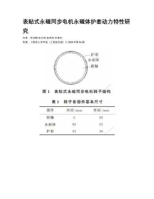
表贴式永磁同步电机永磁体护套动力特性研究作者:李鸿梅张洪信赵清海华青松来源:《青岛大学学报(工程技术版)》2020年第04期摘要:针对表贴式永磁同步电机在运转过程中存在的永磁体因离心力作用会受到较大的拉应力而被损坏的问题,本文主要对表贴式永磁同步电机永磁体护套动力特性进行研究。
给出了转子结构及其强度理论解析模型,对永磁转子各部件的径向、切向、轴向的应力及等效应力进行解析计算,并基于ANSYS Workbench软件,选择合金护套保护永磁体,对转轴、永磁体和护套的受力情况进行有限元仿真分析。
仿真结果表明,适当增大护套与永磁体之间的过盈量,有利于降低永磁体遭受损坏的风险,而且随着护套厚度的增加,护套与永磁体之间所需的过盈量逐渐减小。
该研究为永磁转子的设计提供了理论依据。
关键词:表贴式转子; 永磁同步电机; 强度分析; 有限元分析中图分类号: TM351 文献标识码: A永磁电机因其结构简单、工作效率高、便于维护等优点在各个领域得到广泛的应用[15] 。
依据转子永磁体的安置方式,永磁电机可以分为表贴式和嵌入式两种类型。
由于表贴式永磁电机的性能优良,极间漏磁比较小,电枢反应小,而且制造工艺比较简单,因此采用永磁体为表贴式的结构成为许多永磁电机转子结构的选择。
表贴式永磁同步电机作为一种节能环保型电机,广泛应用到诸多领域[6 9] 。
由于电机运转过程中产生的离心力可能会对抗拉强度很小但抗压强度较大的表贴式永磁体造成损坏,影响永磁同步电机的正常运行,所以需要在永磁体外加一层护套,使永磁体在各个方向上尽可能受到压应力[10 14] 。
目前,比较常用的护套材料分为合金护套与碳纤维护套两大类[15 18] ,碳纤维护套具有质量轻,涡流损耗小等优点,但其工艺复杂,成本较高,导热性能差,装配困难,稳定性很难做到,因此多采用合金护套保护永磁体[19] 。
基于此,本文对表贴式永磁同步电机永磁体护套动力特性进行研究。
由于表贴式永磁同步电机的转子设计为细长型,利用厚壁圆筒理论对转子的径向、切向、轴向应力及等效应力进行解析计算。
碳纤维绑扎表贴式高速永磁电机转子强度分析
王保俊;毕刘新;陈亮亮;杨平西;祝长生
【期刊名称】《浙江大学学报(工学版)》
【年(卷),期】2013(047)012
【摘要】针对表贴式高速永磁电机中分块永磁体转子的强度分析问题,基于弹性力学理论,推导了分块永磁体转子强度的解析表达式.采用解析算法计算碳纤维护套、永磁体以及转轴中的径向应力、切向应力和等效应力,并将解析法的计算结果与有限元法的计算结果进行比较.结果表明:转子在静止和高速转动状况下,解析解都能够准确地计算出表贴式分块永磁体转子的应力分布,且解析解与有限元的误差很小,完全在可接受范围之内.
【总页数】10页(P2101-2110)
【作者】王保俊;毕刘新;陈亮亮;杨平西;祝长生
【作者单位】浙江大学电气工程学院,浙江杭州310027;中船重工集团公司第704研究所,上海200031;浙江大学电气工程学院,浙江杭州310027;中船重工集团公司第704研究所,上海200031;浙江大学电气工程学院,浙江杭州310027
【正文语种】中文
【中图分类】TM351
【相关文献】
1.高速表贴式永磁电机转子机械强度研究 [J], 韩雪岩;何心永;刘欣苗;于占洋
2.高速表贴式永磁电机转子强度分析 [J], 付荣华;王辉
3.基于ANSYS的高速表贴式永磁电机转子强度分析 [J], 张萌;韩雪岩;杨毅
4.高速表贴式永磁电机转子强度分析 [J], 赵亮
5.考虑温升梯度影响的表贴式高速永磁电机转子强度分析 [J], 陈亮亮;冯惊鸿;熊茹;祝长生;伍家驹;李志农
因版权原因,仅展示原文概要,查看原文内容请购买。
表贴式永磁电机磁场的解析计算与分析张河山;邓兆祥;杨金歌;妥吉英;张羽【摘要】利用傅里叶级数法建立表贴式永磁电机电磁场全局解析模型,并分析其空载和负载电磁特性.在二维极坐标系下,将电机求解域划分为永磁体、气隙、定子槽、定子槽开口和辅助槽5类子域.采用分离变量法求解各子域的拉普拉斯方程或泊松方程,并利用边界条件得到通解中的谐波系数,进而得到各子域的解析表达式.计算了电机气隙磁密、空载反电动势、齿槽转矩和电磁转矩等电磁参数,并通过有限元分析验证了解析法的准确性.在此基础上研究了极弧系数、辅助槽尺寸和槽开口宽度对电机齿槽转矩和电磁转矩的影响规律.另外,提出一种不等槽开口宽度配合的解析模型以图减小齿槽转矩峰值和电磁转矩脉动.该方法能反映电机设计性能与尺寸和参数的关系,可用于电机初始设计与优化.【期刊名称】《汽车工程》【年(卷),期】2018(040)007【总页数】9页(P850-857,864)【关键词】永磁电机;解析法;有限元法;齿槽转矩;电磁转矩;不等槽开口【作者】张河山;邓兆祥;杨金歌;妥吉英;张羽【作者单位】重庆大学汽车工程学院,重庆 400044;重庆大学汽车工程学院,重庆400044;重庆大学,机械传动国家重点实验室,重庆 400044;重庆大学汽车工程学院,重庆 400044;重庆大学汽车工程学院,重庆 400044;重庆大学汽车工程学院,重庆400044【正文语种】中文前言永磁电机具有高转矩密度、高效率、高功率密度等优点,广泛应用于电动汽车、船舶等工业领域[1]。
其结构参数对电机性能影响较大,因此,为设计性能优异的电机需要改变和优化电机结构参数,并采用有限元法或解析法分析其电磁场特性。
有限元法可考虑材料非线性影响和分析较复杂结构电机性能,但计算过程耗时、占用资源,且难以对电机特性及其影响因素进行规律性研究,具有明显局限性。
电磁场数值解析法计算量较小,物理概念清晰,能清晰反映电机性能与设计参数的关系,适用于电机设计参数优化,因此逐渐引起国内外学者广泛关注。
表贴式高速永磁同步电机失磁故障及磁体选区渗重稀土研究谢颖;姜佳宁;蔡蔚;任少卿;孙存峻
【期刊名称】《电机与控制学报》
【年(卷),期】2024(28)2
【摘要】针对表贴式高速永磁同步电机永磁体在受到高温、强退磁磁场等因素影响易产生局部不可逆失磁故障问题,本文基于有限元分析方法,分别建立了一台24 kW表贴式高速永磁同步电机的二维和三维仿真计算模型,在计及该电机在各类不同的退磁因素作用下,确定了电机磁体发生局部不可逆失磁故障的位置,并预测了磁体的进一步失磁扩散趋势。
对比了电机在有无失磁故障情况下的空载气隙磁密和反电动势,并研究磁体不可逆失磁故障对电机运行的影响。
由于永磁体易在部分区域发生不可逆失磁,故本文将磁体材料更换为较低牌号,并运用选区渗重稀土技术改善易失磁区域材料特性来提升磁体整体抗失磁能力。
在此基础上,探究了更为合理的重稀土渗入区域及渗入梯度,从而保证在不失电机性能的前提下,实现了重稀土元素的极限应用,为表贴式永磁电机磁体选区渗重稀土技术提供了参考。
【总页数】10页(P44-53)
【作者】谢颖;姜佳宁;蔡蔚;任少卿;孙存峻
【作者单位】哈尔滨理工大学电气与电子工程学院;包头稀土研究院
【正文语种】中文
【中图分类】TM351
【相关文献】
1.表贴式永磁同步电机的抗饱和弱磁控制研究
2.表贴式永磁同步电机弱磁控制方法研究
3.表贴式永磁同步电机永磁体护套动力特性研究
4.表贴式永磁同步电机中高速无位置传感器控制技术比较研究
5.永磁同步电机永磁体局部失磁故障仿真研究
因版权原因,仅展示原文概要,查看原文内容请购买。

永磁同步电机径向电磁力永磁同步电机是一种采用永磁体作为励磁源的同步电机。
它具有结构简单、功率因数高、效率高、体积小、重量轻、响应快等优点,广泛应用于电动汽车、工业生产线等领域。
在永磁同步电机中,径向电磁力是其重要的性能指标之一。
径向电磁力是指电机在运行过程中,产生的沿着径向方向的力。
它的大小和方向直接影响电机的运转稳定性和效率。
永磁同步电机的径向电磁力主要由两部分组成:一是永磁体和定子绕组之间的磁场相互作用产生的磁场力;二是定子绕组中电流与磁场相互作用产生的电磁力。
永磁体和定子绕组之间的磁场相互作用产生的磁场力是永磁同步电机径向电磁力的主要来源。
在电机运行过程中,永磁体的磁场与定子绕组中的磁场相互作用,产生一个径向的力。
当永磁体的磁场与定子绕组的磁场方向相同时,磁场力的大小最大;当二者的磁场方向相反时,磁场力的大小最小。
通过调节永磁体的磁场强度和定子绕组的磁场分布,可以控制永磁同步电机的径向电磁力大小和方向。
定子绕组中电流与磁场相互作用产生的电磁力也会对永磁同步电机的径向电磁力产生影响。
当定子绕组中通过电流时,电流与磁场相互作用,产生一个沿着径向方向的力。
这个力的大小和方向取决于电流的大小和方向,以及磁场的分布。
通过调节定子绕组中的电流大小和方向,可以改变永磁同步电机的径向电磁力大小和方向。
在实际应用中,为了实现永磁同步电机的稳定运行和高效率工作,需要合理设计电机的结构和参数。
首先,需要选择合适的永磁体材料和磁场分布方式,以获得较大的磁场力。
其次,需要选择合适的定子绕组结构和参数,以获得合适大小和方向的电磁力。
同时,还需要考虑电机的散热和保护等问题,以确保电机的安全可靠运行。
永磁同步电机的径向电磁力是其重要的性能指标之一,对电机的运行稳定性和效率有着直接的影响。
合理设计电机的结构和参数,可以实现较大的径向电磁力,提高电机的性能和效率。
随着技术的不断进步,永磁同步电机在各个领域的应用将进一步扩大。
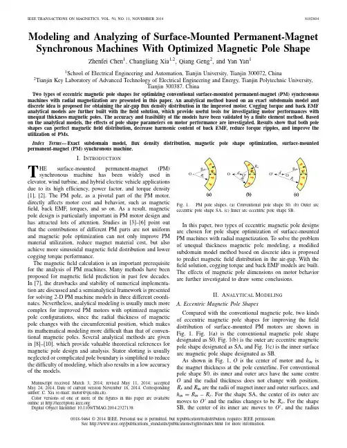
Modeling and Analyzing of Surface-Mounted Permanent-Magnet Synchronous Machines With Optimized Magnetic Pole Shape Zhenfei Chen1,Changliang Xia1,2,Qiang Geng2,and Yan Yan11School of Electrical Engineering and Automation,Tianjin University,Tianjin300072,China2Tianjin Key Laboratory of Advanced Technology of Electrical Engineering and Energy,Tianjin Polytechnic University,Tianjin300387,ChinaTwo types of eccentric magnetic pole shapes for optimizing conventional surface-mounted permanent-magnet(PM)synchronous machines with radial magnetization are presented in this paper.An analytical method based on an exact subdomain model and discrete idea is proposed for obtaining the air-gapflux density distribution in the improved motor.Cogging torque and back EMF analytical models are further built with thefield solution,which provide useful tools for investigating motor performances with unequal thickness magnetic poles.The accuracy and feasibility of the models have been validated by afinite element method.Based on the analytical models,the effects of pole shape parameters on motor performance are investigated.Results show that both pole shapes can perfect magneticfield distribution,decrease harmonic content of back EMF,reduce torque ripples,and improve the utilization of PMs.Index Terms—Exact subdomain model,flux density distribution,magnetic pole shape optimization,surface-mounted permanent-magnet(PM)synchronous machine.I.I NTRODUCTIONT HE surface-mounted permanent-magnet(PM) synchronous machine has been widely used in elevator,wind turbine,and hybrid electric vehicle applications due to its high efficiency,power factor,and torque density [1],[2].The PM pole,as a pivotal part of the PM motor, directly affects motor cost and behavior,such as magnetic field,back EMF,torques,and so on.As a result,magnetic pole design is particularly important in PM motor design and has attracted lots of attention.Studies in[3]–[6]point out that the contributions of different PM parts are not uniform and magnetic pole optimization can not only improve PM material utilization,reduce magnet material cost,but also achieve more sinusoidal magneticfield distribution and lower cogging torque performance.The magneticfield calculation is an important prerequisite for the analysis of PM machines.Many methods have been proposed for magneticfield prediction in past few decades. In[7],the drawbacks and stability of numerical implementa-tion are discussed and a semianalytical framework is presented for solving2-D PM machine models in three different coordi-nates.Nevertheless,analytical modeling is usually much more complex for improved PM motors with optimized magnetic pole configurations,since the radial thickness of magnetic pole changes with the circumferential position,which makes its mathematical modeling more difficult than that of conven-tional magnetic poles.Several analytical methods are given in[8]–[10],which provide valuable theoretical references for magnetic pole design and analysis.Stator slotting is usually neglected or complicated pole boundary is simplified to reduce the difficulty of modeling,which also results in a low accuracy of the models.Manuscript received March3,2014;revised May11,2014;accepted May24,2014.Date of current version November18,2014.Corresponding author:C.Xia(e-mail:motor@).Color versions of one or more of thefigures in this paper are available online at .Digital Object Identifier10.1109/TMAG.2014.2327138Fig.1.PM pole shapes.(a)Conventional pole shape S0.(b)Outer arc eccentric pole shape SA.(c)Inner arc eccentric pole shape SB.In this paper,two types of eccentric magnetic pole designs are chosen for pole shape optimization of surface-mountedPM machines with radial magnetization.To solve the problem of unequal thickness magnetic pole modeling,a modifiedsubdomain model method based on discrete idea is proposedto predict magneticfield distribution in the air-gap.With the field solution,cogging torque and back EMF models are built.The effects of magnetic pole dimensions on motor behaviorare further investigated to draw some conclusions.II.A NALYTICAL M ODELINGA.Eccentric Magnetic Pole ShapesCompared with the conventional magnetic pole,two kinds of eccentric magnetic pole shapes for improving thefielddistribution of surface-mounted PM motors are shown inFig. 1.Fig.1(a)is the conventional magnetic pole shape designated as S0,Fig.1(b)is the outer arc eccentric magneticpole shape designated as SA,and Fig.1(c)is the inner surfacearc magnetic pole shape designated as SB.As shown in Fig.1,O is the center of motor and h m isthe magnet thickness at the pole centerline.For conventional pole shape S0,its inner and outer arcs have the same centreO and the radial thickness does not change with position. R r and R m are the radii of magnet inner and outer surfaces,and h m=R m−R r.For the shape SA,the center of its outer arc moves to O and the radius changes to be R o.For the shapeSB,the center of its inner arc moves to O ,and the radius0018-9464©2014IEEE.Personal use is permitted,but republication/redistribution requires IEEE permission.See /publications_standards/publications/rights/index.html for more information.Fig.2.General subdomain model for PM motors with unequal thicknessmagnetic poles.changes to be R i .d denotes the distance between points Oand O .B.PM Motor ModelingIt is obvious in Fig.1that mathematical illustration becomes more difficult since the radial magnet thickness of SA and SB configurations changes with circumferential angle;thus,the original exact subdomain model [11]can hardly be used for analytical modeling of the improved PM motor.In this paper,discrete idea and superposition principle are adopted to modify and extend the subdomain model method to PM motors with irregular magnetic pole shapes.In Fig.2,a general subdomain model of a 4-pole and 6-slot motor is taken as an example to illustrate the analytical method.The whole domain is divided into three types of subdomains,viz.,magnet (region 1j ),air-gap (region 2),and slots (region 3i ).In this paper,the magnet region is divided into N equal parts,and the j th part is designated as region 1j (j =1,2,...,N ).The thickness of each part can be considered constant if N is large enough.θj denotes the position of region 1j from the pole centerline.R rj and R mj are the inner and outer radii of region 1j ,respectively.In addition,R s and R sb are the radii of stator inner bore and winding slot bottom,respectively.C.Modified Subdomain ModelBefore the modeling,several assumptions are made to simplify the problem as follows:1)end effect is neglected;2)stator/rotor iron has infinite permeability;3)core saturation and loss are neglected;4)demagnetization characteristic of the magnet is linear;5)nonconductive magnet material is used.In polar coordinates,the scalar potentials in the three regions ϕ1j ,ϕ2,and ϕ3i can be expressed by Laplace’s and Poisson’s equations as follows.1)For Region 1jϕ1j = kA 1k r k +B 1k r −k+M cjk r μr (1−k 2)cos (k α)+ kC 1k r k +D 1k r −k +M sjkr μr (1−k 2)sin (k α)k =1(1)ϕ1j =(A 11r +B 11r−1+M cj 1r ln r /2μr )cos α+(C 11r +D 11r −1+M sj 1r ln r /2μr )sin αk =1.(2)2)For Region 2ϕ2=kA 2k r k +B 2k r −kcos (k α)+ k C 2k r k +D 2k r −k sin (k α).(3)3)For Region 3iϕ3i = mX 3im (r /R sb )m παb −(r /R sb )−m παb×sin [(m π/αb )×(α−αi +αb /2)(4)where μr is the relative recoil permeability of magnet and αb is the mechanical angle of winding slot opening.αb =b 0/R s and b 0is the slot opening width.Q is the stator slot number.αi locates the center of the i th winding slot where i =1,2,3,...,Q .k and m are the harmonic coefficients.A 1k -D 1k ,A 2k -D 2k ,and X 3im are the coefficients to be determined.M cjk and M sjk are variables concerning magnets,which can be given asM cjk = 4pB rk πμ0sin k παpj 2p cos (k ωr t )k /p =1,5,7···0others (5)M sjk = 4pB rk πμ0sin k παpj 2p sin (k ωr t )k /p =1,5,7···0others (6)where μ0is the permeability of air,p is the pole pair number,αpj is the pole arc to pole pitch ratio of the j th PM region,B r is the remanent flux density of magnets,and ωr is the rotor rotational speed.To determine the unknown coefficients and obtain the field distribution,the boundary conditions are defined as follows:H α1|r =Rr =0(7)B r 1|r =R m =B r 2|r =R m (8)H α1|r =R m =H α2|r =R m (9)ϕ2|r =R s =ϕ3i |r =R s (10)B r 2|r =R s =B r 3i |r =R s(11)where subscripts r and αdenote the radial and tangential components of variables,respectively.By applying the boundary conditions given by (7)–(11)to (1)–(6),the radial and tangential components of air-gap flux density can be solved asB r 2=kχrck cos (k α)+kχrsk sin (k α)(12)B α2=k χαck cos (k α)+kχαsk sin (k α)(13)where χrck ,χrsk ,χαck ,and χαck are the harmonic amplitudesobtained using subdomain model method and superposition principle.Based on the analytical model of air-gap flux density in (12)and (13),models of cogging torque T c and phase back EMF E x are built as follows:T c =(πl a r 2/μ0)×k(χrck χαck +χrsk χαsk )(14)E x =(N c l a R s /a )×dxB r 2d α/dt x =A ,B ,C (15)CHEN et al.:MODELING AND ANALYZING OF SURFACE-MOUNTED PM SYNCHRONOUS MACHINES 8102804TABLE IM AIN P ARAMETERS OF P ROTOTYPE MACHINESFig.3.FE and analytical predicted air-gap flux densitywaveforms.Fig.4.FE and analytical predicted cogging torquewaveforms.Fig.5.FE and analytical predicted back EMF waveforms.where l a is the lamination length.x denotes the three-phase stator windings.N c is the number of winding turns per coil and a is the number of parallel-circuits per phase.III.F INITE E LEMENT V ALIDATIONIn this section,the finite element (FE)method is employed to validate the analytical model and the FE software is Ansoft Maxwell 15.4-pole/6-slot surface-mounted PM motors with different pole shapes are taken as examples to test the accuracy of the proposed analytical model.The main motor parameters are listed in Table I.The highest harmonic numberconsideredFig.6.Air-gap flux density variation with discrete magnet number N .TABLE IIC ALCULATION T IME OF THE T WO M ETHODSin analytical model K is 40and the number of assumed parts per pole N is 30.Waveforms of air-gap flux density,cogging torque,and back EMF derived by FE and analytical methods are compared in Figs.3–5.As can be seen,all the analytical predictions well illustrate the effects of pole parameters on performance and have excel-lent agreement with the FE results,which verifies the accuracy and feasibility of the proposed method.Besides,the air-gap length of SA configuration changes with circumferential position,while that of SB is still even.Therefore,under the same motor parameters,the equivalent air-gap length of SA is bigger than that of SB.The former has a much smaller root mean square value of flux density,but a better distribution than the latter,which result in lower cogging torque and more sinusoidal back EMF waveform.Since results of the analytical method are calculated by adding N subdomain models with even thickness magnets,the magnetic field solution is affected by the parameter N .In Fig.6,the air-gap flux density variations are given when N is increased from 1to 50.As can be seen,the results stay unchanged when N is larger than 10,which indicates that the analytical method is stable if N is large enough.In Table II,the time consumed by analytical method and FE method is compared when N is 30.It shows that the analytical method is much faster than FE method,which can improve the efficiency of motor design and analysis.IV.E FFECT OF M AGNET D IMENSIONSON M OTOR B EHAVIORBased on the proposed analytical model in (14)and (15),effects of magnet dimensions on motor behavior are inves-tigated.Variations of cogging torque T c ,fundamental com-ponent amplitude of back EMF E 0,and its total harmonic distortion (THD)with h m and d are shown in Figs.7–9.Some conclusions can be drawn from the above results.1)In Fig.7,cogging torque decreases with either smaller h m or larger d .But the difference is that cogging torque per unit volume continues to decrease when d increases,8102804IEEE TRANSACTIONS ON MAGNETICS,VOL.50,NO.11,NOVEMBER2014Fig.7.Cogging torque variation with h m and d .(a)SA.(b)SB.Fig.8.Back EMF amplitude variation with h m and d .(a)SA.(b)SB.Fig.9.Back EMF THD variation with h m and d .(a)SA.(b)SB.while it increases when h m decreases.This illuminates that cogging torque cannot be effectively eliminated by reducing magnet thickness.Applying the magnet pole shape optimization method would be more useful.2)Like cogging torque,back EMF amplitude gets smaller with the decrease of h m or the increase of d as shown in Fig.8.Fortunately,the contribution of per unit volume increases,while the magnitude of back EMF gets lower.This implies that pole shape optimization can improve the utilization of PM and save the cost of PM machines.3)Apart from the amplitude of back EMF,harmonics is also a focus in PM motor analysis.In Fig.9,the THD of back EMF can hardly vary with h m .But it decreases evidently with the increase of d ,which suggests that higher performance of PM motor could be achieved by employing SA and SB pole configurations since they can not only eliminate cogging torque,but also reduce back EMF harmonics.4)In addition,although SA and SB configurations have similar effects on motor behavior,SA is more sensitive to d than SB.This is because for SB configuration,only pole shape is changed,while its air-gap distribution is still uniform.But for SA configuration,it has not only a sinusoidal magnetic pole,but also an unevenlydistributed air-gap,which will enhance the impact of parameter d .V.C ONCLUSIONEccentric magnetic pole is an effective approach to improv-ing PM motor design.However,uneven thickness of magnetic pole also increases the difficulty of analytical modeling.In this paper,an accurate analytical method is proposed by modifying subdomain model method with discrete idea.With the proposed models,the effects of PM dimensions,h m and d ,on motor behavior are investigated.This paper shows that h m directly affects the magnitude of flux density and further affects the magnitudes of cogging torque and back pared with h m ,parameter d mainly affects the spatial distribution of flux density rather than changing its rger d would produce better flux density distribution,result-ing in smaller cogging torque and more sinusoidal back EMF waveform though it also somewhat decreases its magnitude.Thus,a balance between design requirements,ensuring motor electromagnetic performance and meanwhile reducing back EMF THD and torque ripples,may be achieved by choosing appropriate pole dimensions.A CKNOWLEDGMENTThis work was supported in part by the National Key Basic Research Program of China (973Program)under Grant 2013CB035602and in part by the Key Program,National Natural Science Foundation of China,under Grant 51037004.R EFERENCES[1]Z.Q.Zhu and D.Howe,“Electrical machines and drives for electric,hybrid,and fuel cell vehicles,”IEEE Trans.Magn.,vol.44,no.1,pp.52–65,Jan.2008.[2] C.C.Chan,“The state of the art of electric and hybrid vehicles,”Proc.IEEE ,vol.90,no.2,pp.247–275,Feb.2002.[3]M.R.Dubois,H.Polinder,and J.A.Ferreira,“Magnet shaping forminimal magnet volume in machines,”IEEE Trans.Magn.,vol.38,no.5,pp.2985–2987,Sep.2002.[4]M.R.Dubois,H.Polinder,and J. A.Ferreira,“Contribution ofpermanent-magnet volume elements to no-load voltage in machines,”IEEE Trans.Magn.,vol.39,no.3,pp.1784–1791,May 2003.[5]Y .Pang,Z.Q.Zhu,and Z.J.Feng,“Cogging torque in cost-effectivesurface-mounted permanent magnet machines,”IEEE Trans.Magn.,vol.47,no.9,pp.2269–2276,Sep.2011.[6]skaris and A.G.Kladas,“Permanent-magnet shape optimizationeffects on synchronous motor performance,”IEEE Trans.Ind.Electron.,vol.58,no.9,pp.3776–3783,Sep.2011.[7] B.L.J.Gysen,K.J.Meessen,J.J.H.Paulides,and E.A.Lomonva,“General formulation of the electromagnetic field distribution in machines and devices using Fourier analysis,”IEEE Trans.Magn.,vol.46,no.1,pp.39–52,Jan.2010.[8]J.De La Ree and N.Boules,“Magnet shaping to reduce induced voltageharmonics in PM machines with surface mounted magnets,”IEEE Trans.Energy Convers.,vol.6,no.1,pp.155–161,Mar.1991.[9]S.M.Jang,H.Park,J.Y .Choi,K.J.Ko,and S.H.Lee,“Magnetpole shape design of permanent magnet machine for minimization of torque ripple based on electromagnetic field theory,”IEEE Trans.Magn.,vol.47,no.10,pp.3586–3589,Oct.2011.[10]Y .B.Yang,X.H.Wang,C.Q.Zhu,and C.Z.Huang,“Reducingcogging torque by adopting isodiametric permanent magnet,”in Proc.4th IEEE ICIEA ,May 2009,pp.1028–1031.[11]Z.Q.Zhu,L.J.Wu,and Z.P.Xia,“An accurate subdomain modelfor magnetic field computation in slotted surface-mounted perma-nent machines,”IEEE Trans.Magn.,vol.46,no.4,pp.1100–1115,Apr.2010.。
调速永磁同步电动机的电磁设计与磁场分析电磁设计是指针对给定的电机参数要求,确定合理的线圈结构、磁场分布和磁路特性等方面的技术设计过程。
其目标是在满足规定的机械特性、电磁特性和工艺要求的前提下,使电机具有最佳的效率、功率因数和转矩密度等性能。
首先,需要确定合适的线圈结构。
根据电机的功率、转速和负载要求等参数,选择合适的线圈类型、匝数和截面形状等。
其中,多层绕组结构可以提高电机的功率密度,而单层绕组更易于制造,降低了制造成本。
其次,需要进行磁场分析。
通过计算机仿真软件或有限元方法,建立电机的磁场模型,分析电机各部分的磁场分布和特性。
磁场分析主要包括磁感应强度、磁通分布、磁势能、磁压力等参数。
通过优化磁场分布,可以提高电机的转矩密度和效率。
磁场分析的过程中,还需要进行磁路设计。
磁路设计包括永磁体的选型和磁路结构的设计。
永磁体的选型要考虑其磁化特性、矫顽力和温度稳定性等因素,以满足电机对磁场的高稳定性和大转矩要求。
磁路结构的设计要优化磁路的传导能力和磁阻损耗,以减小电机的铜损和磁铁损耗,提高电机的效率。
另外,还需要考虑绕组的热设计。
在电磁设计和磁场分析的基础上,进行绕组的热分析和散热设计。
通过合理的冷却措施和散热结构的设计,避免电机过热,保证电机的可靠运行。
同时,绕组的电磁阻抗特性和电磁噪声也是电磁设计和磁场分析的重要考虑因素。
通过优化线圈结构和绕组的布局方式,可以减小电机的电磁阻抗和电磁噪声,提高电机的工作效果和可靠性。
总之,调速永磁同步电动机的电磁设计和磁场分析是确保电机性能的重要环节。
通过合理的线圈结构、磁场分布和磁路特性等技术设计,可以提高电机的效率、功率因数和转矩密度等性能指标,满足电机在不同应用领域的要求。
同时,绕组的热设计、电磁阻抗特性和电磁噪声等问题也需要合理考虑,以确保电机的可靠工作。
永磁同步电机卧装轴向磁拉力的计算及平衡措施李祥成;王迎春;牛安周【摘要】通过分析永磁同步电机总装配的特点及各种工艺方案的优缺点,提出了研究永磁同步电机总装配的轴向磁拉力的必要性.对轴向磁拉力产生的机理进行了介绍,并对永磁同步电机总装配的轴向磁拉力工程计算公式进行了推导.以一台24极3200kW/500r/min的永磁同步电机为例进行计算和实际装配验证了卧装时的轴向磁拉力计算公式的可行性.最后,提出了防止和减小轴向不平衡磁拉力不利影响的有效措施.【期刊名称】《防爆电机》【年(卷),期】2018(053)005【总页数】3页(P19-21)【关键词】轴向磁拉力;永磁同步电机;卧装【作者】李祥成;王迎春;牛安周【作者单位】中车永济电机有限公司,山西永济044502;中车永济电机有限公司,山西永济044502;中车永济电机有限公司,山西永济044502【正文语种】中文【中图分类】TM303.30 引言永磁同步电机的总装配一直是个工艺难点。
装有磁钢的转子吸附力极强,定转子气隙较小,装配时因定、转子偏心产生极大的径向单边磁拉力而发生碰撞,严重时导致定、转子吸附在一起难以分开,甚至报废,容易造成人身伤害[1]。
永磁同步电机的总装配方案主要有立式装配、卧式装配两种方案。
立式装配使用专用的工装保证定子、转子的同轴度,利用转子的自重使定子、转子铁心轴向最终对齐。
卧式装配有两种方案:方案一是使用类似镗床改制的非标永磁电机总装机,将转子连接延长工艺轴安装于主轴顶尖和尾座顶尖之间,定子安装于总装机滑台上,移动滑台,使定子、转子铁心轴向对齐来完成装配。
方案二是将定子固定于安装平台上,使用专用工装保证定子、转子的同轴度,转子两端轴向不固定,通过轴向推进转子使定子、转子铁心轴向对齐。
卧式装配方案二具有明显的优势:一方面避免了立式装配时定子、转子及整机繁琐翻转工艺的过程以及翻转过程中的安全隐患等缺点;另一方面解决了卧式装配方案一中顶尖之间支撑的跨度大,大功率永磁电机装配时转轴和延长工艺轴变形大,容易导致定、转子吸附在一起,导致装配失败的问题。
调速永磁同步电动机的电磁设计与磁场分析1 引言与传统的电励磁电机相比,永磁同步电动机具有结构简单,运行稳定;功率密度大;损耗小,效率高;电机形状和尺寸灵活多变等显著优点,因此在航空航天、国防、工农业生产和日常生活等各个领域得到了越来越广泛的应用。
随着电力电子技术的迅速发展以及器件价格的不断下降,越来越多的直流电动机调速系统被由变频电源和交流电动机组成的交流调速系统所取代,变频调速永磁同步电动机也应运而生。
变频调速永磁同步电动机可分为两类,一类是反电动势波形和供电电流波形都是理想矩形波(实际为梯形波)的无刷直流电动机,另一类是两种波形都是正弦波的一般意义上的永磁同步电动机。
这类电机通常由变频器频率的逐步升高来起动,在转子上可以不用设置起动绕组。
本文使用Ansoft Maxwell 软件中的RMxprt 模块进行了一种调速永磁同步电动机的电磁设计,并对电机进行了性能和参数的计算,然后将其导入到Maxwell 2D 中建立了二维有限元仿真模型,并在此模型的基础上对电机的基本特性进行了瞬态特性分析。
2 调速永磁同步电动机的电磁设计2.1 额定数据和技术要求调速永磁同步电动机的电磁设计主要包括主要尺寸和气隙长度的确定、定子冲片设计、定子绕组的设计、永磁体的设计等.通过改变电机的各个参数来提高永磁同步电动机的效率η、功率因数cos ϕ、起动转矩st T 和最大转矩max T .本例所设计永磁同步电动机的额定数据及其性能指标如下:计算额定数据:(1) 额定相电压:N 220V U U ==(2) 额定相电流:3N N N N N1050.9A cos P I mU ηϕ⨯== (3) 同步转速:160=1000r /min f n p= (4) 额定转矩:3N N 19.5510286.5N m P T n ⨯== 2.2 主要尺寸和气隙长度的确定永磁电机的主要尺寸包括定子内径和定子铁心有效长度,它们可由如下公式估算得到:2i11P D L C n '= N N N cos E K P P ηϕ'=, 6.1p Nm dp C K K AB δα=' 式中,i1D 为定子内径,L 为定子铁心长度,P '为计算功率,C 为电机常数。
表贴式永磁同步轮毂电机磁场分析与优化设计表贴式永磁同步轮毂电机磁场分析与优化设计摘要:表贴式永磁同步轮毂电机是一种新型的电动机,具有结构紧凑、功率密度高、拆装方便等优点,在现代交通工具中得到了广泛的应用。
本文通过对表贴式永磁同步轮毂电机的磁场进行分析与优化设计,进一步提高其运行效率和性能。
1. 引言随着电动汽车的普及,对电动机的性能要求不断提高。
表贴式永磁同步轮毂电机由于其结构紧凑,可以直接连接轮毂,不需要传动装置,因此具有较高的功率密度,适用于电动汽车等场景。
本文针对表贴式永磁同步轮毂电机的磁场进行分析与设计优化,以提高电机的效率和性能。
2. 表贴式永磁同步轮毂电机的磁场分析表贴式永磁同步轮毂电机的磁场分析是设计优化的基础。
该电机的主要磁场由定子的励磁电流和永磁体的磁场组成。
在磁场分析中,可以采用有限元法进行模拟和计算。
2.1 定子励磁电流的磁场分析表贴式永磁同步轮毂电机的定子通常由多个绕组组成,每个绕组中的电流都会产生磁场。
通过有限元法建立定子的磁场模型,可以计算出各个绕组的励磁磁场分布情况。
2.2 永磁体的磁场分析永磁体是表贴式永磁同步轮毂电机中的重要组成部分,它产生的磁场直接影响电机的性能。
通过有限元法对永磁体进行磁场分析,可以得到永磁体的磁场分布情况,进一步确定电机的磁场分布情况和磁场强度。
3. 表贴式永磁同步轮毂电机的磁场优化设计在磁场分析的基础上,可以进行磁场的优化设计,以提高电机的效率和性能。
主要的优化设计包括:3.1 绕组设计优化通过优化绕组的布局和参数选择,可以降低电阻和电磁损耗,提高电机的效率。
一般可以通过调整绕组的截面积、匝数等参数,来优化绕组的设计。
3.2 永磁体设计优化永磁体的设计对电机的性能影响较大。
通过优化永磁体的材料选择和形状设计,可以提高电机的磁场强度和磁能密度,从而提高电机的输出功率和效率。
3.3 磁路设计优化在表贴式永磁同步轮毂电机中,磁路设计的合理性直接影响电机的性能。
万方数据
万方数据
万方数据
万方数据
表贴式调速永磁同步电动机径向磁拉力分析
作者:梁文毅, LIANG Wen-yi
作者单位:杭州易泰达科技有限公司,浙江,杭州,310053
刊名:
微特电机
英文刊名:SMALL & SPECIAL ELECTRICAL MACHINES
年,卷(期):2011,39(5)
1.陈永校;诸自强;应善成电机噪声的分析和控制 1987
2.陈世坤电机设计 2000
3.黄礼文;王宗培电动机噪声理论和控制技术的进展[期刊论文]-电工技术学报 2000(10)
4.王泽忠;严烈通异步电机气隙谐波磁场的分解合成法[期刊论文]-华北电力学院学报 1994(09)
5.黄开胜;张城生;杨杰笼型感应电动机电磁噪声及其控制 1995(06)
6.秦萌青;唐会智交流电机中的两种谐波磁场 1998(06)
7.李伟异步电动机的噪声控制[期刊论文]-防爆电机 2005(02)
8.Wang J;Xia Z P;Long S A Radial force density and vibration characteristics of modular permanent magnet brushless AC machine[外文期刊] 2006(06)
1.王广生.黄守道.高剑.WANG Guang-sheng.HUANG Shou-dao.GAO Jian永磁同步电动机过载特性及其控制策略[期刊论文]-电机与控制应用2011,38(5)
2.鲍庭瑞.姚春元三相永磁同步伺服系统的初始定位[期刊论文]-铜陵学院学报2008,7(3)
3.刘伟.陈丽香.唐任远定子齿顶开辅助槽削弱永磁电机齿槽转矩的方法[会议论文]-2009
4.李勇.姜新通.史庆夫.酒晨霄.刘彦彬.陆永平.LI Yong.JIANG Xin-tong.SHI Qing-fu.JIU Chen-xiao.LIU Yan-bin.LU Yong-ping基于Ansoft 的IPM永磁同步电动机磁场计算[期刊论文]-微特电机2011,39(6)
5.赵君.刘卫国.骆光照.曾重.赵跃齐.ZHAO Jun.LIU Wei-guo.LUO Guang-zhao.ZENG Zhong.ZHAO Yue-qi一种矿用机车永磁同步交流牵引系统设计与实现[期刊论文]-微特电机2010,38(10)
6.李天平.LI Tianping一种高速涡轮冷却风扇电动机的设计[期刊论文]-微电机2011,44(3)
7.林岩.王震宇.杨小峰.申修沇.Lin Yan.Wang Zhenyu.Yang Xiaofeng.Shen Xiuyan空调器用正弦波调速永磁同步电动机的开发与可靠性分析[期刊论文]-电气技术2010(11)
8.唐任远.徐广人.徐衍亮.陶爱华.安忠良电机用永磁体局部工作点及局部失磁研究[会议论文]-1998
9.孙剑波.詹琼华开关磁阻电动机的径向力计算[期刊论文]-微特电机2005,33(1)
10.杨云峰.李丽石油钻机用永磁同步电动机电磁场有限元分析[期刊论文]-机电一体化2011,17(3)
本文链接:/Periodical_wtdj201105007.aspx。