中英文文献翻译-轮毂式电动汽车驱动系统
- 格式:doc
- 大小:84.50 KB
- 文档页数:8

轮毂式电动汽车驱动系统外文文献翻译、中英文翻译、外文翻译The wheel type electric car is a type of electric car thatutilizes a driving system。
There are two main forms of this system: the direct driving type ___。
This system is installed on the wheel hub of the motor。
___。
n。
main cer。
___。
it allows for the ___。
making electric control technology possible。
As a result。
the wheel type electric car is expected to e the ___ electric cars.2.Advantages and disadvantagesThe wheel type electric car has many advantages。
First。
it has a simple and compact structure。
Second。
it has high n efficiency。
which improves the overall performance of the car。
Third。
it has good ___。
it has a low noise level。
However。
there are also some disadvantages。
First。
the cost of the wheel type electric car is relatively high。
Second。
the maintenance costis also high。
Third。
the wheel type electric car has ___.The wheel type electric car has a simple and compact structure。
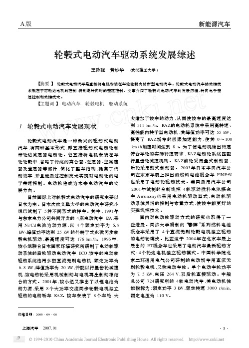
A 版新能源汽车轮毂式电动汽车驱动系统发展综述王玲珑 黄妙华 (武汉理工大学)【摘要】 轮毂式电动汽车是直接将电机安装在车轮轮毂内的新型电动汽车。
轮毂式电动汽车的关键技术就在于对轮边电机的控制,特别是转向时的差速控制。
文章介绍了轮毂式电动汽车的发展历程、转向电子差速控制和关键技术。
【主题词】 电动汽车 轮毂电机 驱动系统收稿日期:2006-09-081 轮毂式电动汽车发展现状轮毂式电动汽车是一种新兴的驱动式电动汽车,有两种基本形式,即直接驱动式电动轮和带轮边减速器电动轮。
它直接将电机安装在车轮轮毂中,省略了传统的离合器、变速器、主减速器及差速器等部件,简化了整车结构,提高了传动效率,并且能通过控制技术实现对电动轮的电子差速控制。
电动轮将成为未来电动汽车的发展方向。
目前国际上对轮毂式电动汽车的研究主要以日本为主。
日本庆应义塾大学的电动汽车研究小组已试制了5种不同形式的样车。
其中,1991年与东京电力公司共同开发的4座电动汽车I Z A ,采用N i 2Cd 电池为动力源,以4个额定功率为618k W 、峰值功率达到25k W 的外转子式永磁同步轮毂电机驱动,最高速度可达176k m /h 。
1996年,该小组联合日本国家环境研究所研制了电动轮驱动系统的后轮驱动电动汽车ECO ,该车的电动轮驱动系统选用永磁直流无刷电动机,额定功率为618k W ,峰值功率为20k W ,并配以行星齿轮减速机,该电动轮采用机械制动与电机再生制动相结合的方式。
2001年,该小组又推出了以锂电池为动力源,采用8个大功率交流同步轮毂电机独立驱动的电动轿车K AZ 。
该车安装了8个车轮,大大增加了该车的动力,从而使该车的最高速度达到311k m /h 。
K AZ 的电动轮系统中采用高转速、高性能内转子型电动机,其峰值功率可达55k W ,提高了K AZ 轿车的极限加速能力,使其0~100k m /h 加速时间达到8s 。
为了使电动机输出转速符合车轮的实际转速要求,K AZ 电动轮系统匹配行星齿轮减速机构。
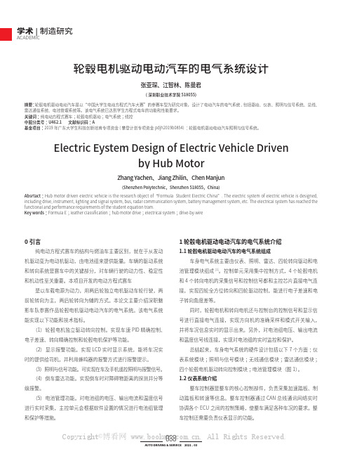
学术|制造研究ACADEMIC轮毂电机驱动电动汽车的电气系统设计(深圳职业技术学院 518055)张亚琛、江智林、陈曼君摘要:轮毂电机驱动电动汽车是以“中国大学生电动方程式汽车大赛”的参赛车型为研究对象,设计了电动汽车的电气系统,包括驱动、仪表、照明与信号系统、总线、雷达通信系统、电池管理系统等。
该电气系统已达到学生方程式电车的功能和性能要求。
关键词:纯电动方程式赛车;轮毂电机驱动;电气系统;线控中图分类号:U462.1 文献标识码:A 基金项目:2019年广东大学生科技创新培育专项资金(攀登计划专项资金pdjh2019b0854):轮毂电机驱动电动汽车照明与信号系统。
0 引言纯电动方程式赛车的结构与燃油车主要区别,就在于从发动机驱动变为电动机驱动,由电池组来提供能量。
车辆的驱动系统和转向系统是赛车中的关键部分,对车辆行驶的动力性、稳定性和机动性至关重要。
本项目开发的电动方程式赛车是以车载电源为动力,用两后轮独立电机驱动车轮行驶,两前轮转向为主,两后轮转向为辅的方式。
本论文主要介绍深职魅影车队参赛作品轮毂电机驱动电动汽车的电气系统。
该电气系统能实现以下功能和技术指标。
(1)轮毂电机独立驱动转向控制。
实现车速PID 精确控制、电子差速、转向精确控制和轮毂电机保护等功能。
(2)显示报警功能。
实现LCD 实时显示系统,能将车况实时的提供给司机,并利用蜂鸣器的报警方式进行报警提示。
(3)照明与信号功能。
可实现在车及手机遥控照明与报警信号。
(4)倒车雷达功能。
实现倒车时对障碍物距离的探测并分等级报警。
(5)电池管理功能。
对电池组的电压、输出电流和温度信号进行实时采集,主控单元会根据软件设置的情况进行电池组管理和保护等措施。
1 轮毂电机驱动电动汽车的电气系统介绍1.1 轮毂电机驱动电动汽车的电气系统组成车身电气系统主要由仪表、照明、雷达、四轮转向驱动和电池管理模块组成[1]。
控制单元采用集中控制方式,4个轮毂电机和4个转向电机的采集信号和控制信号都和主控芯片直接电气连接,实现四轮全方位转向和四轮驱动控制,能进行电子差速和电子转向角度差等。

轮毂电机驱动系统在电动汽车上的应用作者:吕金山秦滔文学肖建军来源:《今日自动化》2021年第11期[摘要]輪毂电机驱动系统被应用于电动汽车之上,有着较为优良的表现。
轮毂电机驱动系统在应用在呈现部分问题,例如电动汽车生命周期管理、汽车运行可靠性等,针对此类问题对轮毂电机驱动系统实际应用中进行改进优化,加装冷却风扇、使用电子差速控制系统、控制零部件质量等。
通过这些技术优化和改进,进一步提升了轮毂电机驱动系统在电动汽车上的应用广度和深度,为电动汽车发展添砖加瓦。
[关键词]轮毂电机;电差速;电动汽车;应用分析[中图分类号]U469.72 [文献标志码]A [文章编号]2095–6487(2021)11–00–02Application of Hub Motor Drive System in Electric VehicleLV Jin-shan, Qin Tao, Wen Xue, Xiao Jian-jun[Abstract]Hub motor drive system is applied to electric vehicle, which has a better performance. The application of hub motor drive system presents some problems, such as electric vehicle life cycle management, vehicle operation reliability, etc. in view of these problems, the practical application of hub motor drive system is improved and optimized, such as adding cooling fan,using electronic differential control system, controlling the quality of parts, etc. Through the optimization and improvement of these technologies, the application breadth and depth of hub motor drive system in electric vehicles are further improved, which contributes to the development of electric vehicles.[Keywords]hub motor; electric differential; electric vehicle; application analysis轮毂电机技术在实际应用的过程中表现出了非常明显的优势,即占用资源较少、整车结构简洁、可利用空间较大、应对故障能力较强、车辆操控性能好等,并且通过对此技术的应用,还有效的实现了电子差速的有效控制。

附录A外文翻译英文资料翻译[原文]Wheel type electric cars driving system1. Development situation and overviewWheel type electric car is a kind of driving type electric cars, there are two basic forms, namely direct driving type electric wheels and belt wheel edges reducer electric wheels. It will be installed on the wheel hub of motor is omitted, traditional clutch, the transmission, the main reducer and differential unit etc, simplifies configuration and improve the transmission efficiency, and to realize the electric control technology through the electronic differential control wheels. Electric wheel will become the future development direction of electric cars.The electric car wheel type of the study in Japan. Japan's keio university of electric car research group has developed five different forms of vehicles. In 1991, with Tokyo electric power company jointly developed by IZA electric car seat, Cd - battery power method, with four rated power for 6.8 kW, 25kW reached the peak power of the rotor permanent magnet synchronous motor driving wheel speed can reach the highest, 176km/h. In 1996, the Japanese national institute of environmental groups jointly developed electric wheel drive system of rear wheel drive electric cars, the ECO electric wheel drive system chooses permanent brushless dc motor, power rating for 6.8 kW, for 20kW peak power, and planetary gear reducer, the electric wheels adopt mechanical braking and motor is a combination of regenerative braking. In 2001, the group launched by using lithium battery for power supply, eight high power ac synchronous motor driving wheel independent KAZ electric car. The installation of the eight wheels, and greatly increased the power, thereby the highest speed 311 km/h. The electric system KAZ used in high speed, high performance of motor rotor inside, the peak power can reach 55 kW, improve the ability of the limit speed KAZ cars, make its 0 ~ 100km/h acceleration time reach 8s. In order to make the motor output speed with the actual requirements, wheel rotation KAZ electric system matching planet gear. Using KAZ front disc brake drum brake using, rear. In 2003, Toyota motor company launched in Tokyo motor show the fuel cell concept car is also used to end an argument - N electric wheel drive technology. General motors corp. In 2001, the new trial wire four wheel drive car fuel cell concept also USES electric wheel drive Autonomy,electric wheel drive system of flexible control and arrangement, the better able to realize control technology.Domestic electric wheel drive mode study also made some progress. Tongji university "chunhui" series of fuel cell vehicles using the concept of four brushless dc motor driving wheel independent electric wheels module. Byd in 2004 Beijing auto ET concept car also adopted new drive electric car: four wheel drive motor independent pattern edge. Chinese academy of sciences, Beijing three-ring general electric company developed electric car brushless dc motor with wheels, say again electric wheels. A single wheel electric power, voltage 7.5 kW, double rear 264 V direct drive. The Chinese institute of four wheel corporation 724 electric automobile, motor performance index for the power rating: 3 kW, rated speed 3000r/min, rated voltage is 110 V.2.Structure analysisWheel electric drive system have direct driving type electric wheels and belt wheel edges reducer electric wheels are two basic forms. It depends on the rotor speed is using high-speed rotor motor or within. Direct drive a car with the rotor motor, electric wheels and a complete parts assembly wheel, electronic differential mode, motor, decorate in the wheels within wheels drive vehicle driven directly. Its main advantage is the motor, small volume, light quality and low cost, high transmission efficiency, compact structure, vehicle structure layout and design, also facilitate the retrofit design. This electric wheel directly in the installation of the wheel rim driving wheel rotation. But when the electric car in large torque, need is installed in the direct drive motor must type electric wheels can provide large in low torque. In order to make the car can have good performance, motor must also has a wide range of torque and speed adjustment. The work of the impact and vibration and the wheel rims wheels, request must be strong and reliable supporting, at the same time, because of the spring load, to ensure the quality of the comfort of vehicle suspension systems, elastic elements and damping element optimization design, motor output torque and power is limited, the system of wheel size high cost.Belt wheel gear wheel drive electric power while using high-speed rotor motor system in modern high-performance electric cars, suitable for the operation. It KuangYongChe originated from the traditional electric wheels, belongs to the slowdown driven type, the electric motor speed wheels allow in operation, usually the highest speed motor design in 4000-20000 r/min, its purpose is to obtain higher than the power, and the other performance of motor without special requirement, and can be used in ordinary speed motor rotor. In motor and reducer institution arrangement between the wheels, deceleration and increase torque of electric cars, thus ensuring the role in the speed to make enough big torque. Motor output shaft through institutions and wheel drive shaft, motor bearing not connected directly under the load and the road wheels, improve the working conditions of the bearings, Adoptsfixed planetary gear reducer, ratio of the system with large range of speed and torque, give full play to the characteristics of the motor speed, eliminate the motor torque and power under the influence. Size wheel In the design of main consideration should be given to the solution of gear noise and lubrication problem, work of motor and internal system structure design requirements. Figure 1 for wheel edges deceleration ware electric wheels.3.Wheel type electric car key technology(1)The wheel motor and its control technologyCurrently used electric wheels of the rotor motor speed and high-speed rotor motor are within the radial magnetic flux permanent magnet motor wheel. Within the high-speed rotor motor structure and the traditional permanent magnet synchronous motor or brushless dc motor are basically the same. The highest speed motor coil and mainly by friction loss and variable factors such as organization ability. As the rotor wheeled permanent magnet motor electric car driven directly by the actuator, motor NdPeB installation of the surface of the rotor surface-mounted stator slots structure more rare. The wheel diameter had substructure of constraint conditions make the armature diameter increase and improve the motor ability, At the same time, had made motor cooling conditions worsen substructuring for long time, overload ability have certain effect. Adopt stator slots structure, few &reduce volume, simplified structure, to generate electricity needed to improve the indexes of harmonic. Magnetic rotor position sensor adopts magnetic resistance type, and motor multipole rotating transformer ontology integration installation, compact structure.Motor driven by axial Angle transform technique, use axis rotation Angle transform chip will output signal is transformed into digital signals, for the current instruction position of each phase of the synthesis of circuit current instruction, With the current negative feedback signal current instruction by current regulator (CR), control type inverter power circuit, SPWM drive motor running.Wheel type electric vehicle generally has two or four wheel edges of multiple motor, implement coordinated control. The key to achieve technology is the drive motor operating control, including the vehicle steering stability control, differential control system dynamic performance optimization and control, etc. In the stability control, traction control system for the main research direction, the comprehensive energy strategy in battery technology progress, not enough before are equally important. In order to research on vehicles, electric cars and the optimization design of effective mathematical model and the rapid and effective system operation control algorithm is also world research hotspot.(2) Energy and energy management systemBattery electric vehicle is the source, is also restricted the development of key factors of electric cars. Electric car battery is the main performance indexes than energy, energy density, power, circle life and cost, etc. To make electric cars and fuel automobilecompetition, the key to develop high energy, power and long-life efficient battery.So far, the electric car battery after three generations of development, has achieved breakthrough progress. The first generation is lead-acid batteries, mainly is the valve-control lead-acid battery (VRLA), due to its high price lower than energy, and discharge, high magnification is currently only high-volume production electric car batteries. Second generation is mainly alkaline battery, have Ni - Cd, Ni fd-mh, making - S, Li ion - and Zn/Air etc. Various battery, the ratio of energy and power than lead-acid battery is high, can greatly improve the performance of the electric vehicle dynamic range and lead-acid batteries, but the price is high. Article 3 the batteries in fuel cells. Fuel cells directly will fuel energy into electricity, high efficiency, energy transformation of energy and power than than all high, and can control the reaction process, energy conversion process can be continuous, is the ideal car batteries, but is still in the development stage, and some key technology is still a breakthrough.Because the electric vehicle Co., LTD, its energy vehicle driving car fuel mileage far less than the level of energy management system, the purpose is to maximize the use of the vehicle, increase energy limited trip mileage. Intelligent energy management systems acquisition from each subsystem, the sensor information input these sensors and temperature sensor, including car when the source current and voltage recharge sensor, motor current and voltage sensor, speed and acceleration sensor and the outside environment and climate, sensors, etc. Energy management system can realize the following basic functions: the energy distribution system, The prediction of the surplus energy and continue to trip mileage, Provide the best driving mode, When the regenerative braking rationally adjust the renewable energy, Automatic temperature control and adjustment. Intelligent management system as the brain, electric car, with great flexibility and adaptability.4.ConclusionThe paper introduces development status of electric vehicle wheel type and structure characteristics, illustrates the steering wheel motor-driven car control model and key technologies. Compared with the traditional electric cars and electric car wheel type of vehicle structure, transmission efficiency and dynamic performance, range, etc are very obvious advantages, is the future development direction of electric cars. At present, low quality of high power, wheel motor research is still hot. At the same time, the power steering wheel, driving, braking torque and speed of motor control is the key and difficult point for future research.轮毂式电动汽车驱动系统1、发展现状轮毂式电动汽车是一种新兴的驱动式电动汽车,有两种基本形式,即直接驱动式电动轮和带轮边减速器电动轮。
轮毂电驱动系统、驱动轮和车辆技术领域本发明涉及汽车领域,尤其是涉及一种轮毂电驱动系统、驱动轮和车辆。
背景技术相关技术中,纯电动汽车动力系统中,现有的轮毂电机采用多拍行星齿轮机构进行减速,而在需要进一步增加减速比时,空间的限制而导致电机或减速机构的体积受限,电机的扭矩和减速比均无法满足更大的驱动扭矩的需求。
发明内容本发明旨在至少解决现有技术中存在的技术问题之一。
为此,本发明的一个目的在于提出一种用于车辆的轮毂电驱动系统,该轮毂电驱动系统的结构紧凑、轴向尺寸小,且可以实现大传动比和大扭矩的需求。
本发明还提出一种具有上述轮毂电驱动系统的驱动轮。
本发明还提出一种具有上述驱动轮的车辆。
根据本发明的用于车辆的轮毂电驱动系统,所述轮毂电驱动系统设置在所述车辆的驱动轮的轮毂内,所述轮毂电驱动系统包括:电机;轮毂减速器,所述轮毂减速器包括:小行星轮系,所述小行星轮系包括:小太阳轮、小行星架和小齿圈,所述小太阳轮、所述小行星架和所述小齿圈中的一个固定以构造为固定端、一个与电机所述电机相连以构造为小行星轮系动力输入端、一个构造为小行星轮系动力输出端;大行星轮系,所述大行星轮系包括:大太阳轮、大行星架和大齿圈,所述大太阳轮、所述大行星架和所述大齿圈中的一个固定以构造为固定端、一个与小行星轮系动力输出端相连以构造为大行星轮系动力输入端、一个构造为大行星轮系动力输出端且与所述轮毂相连;其中所述小行星轮系和所述大行星轮系同轴径向布置,所述大行星轮系动力输入端与所述小行星轮系动力输出端在径向上至少部分重叠。
根据本发明的轮毂电驱动系统,轮毂减速器中通过将小行星轮系和大行星轮系的设置,使轮毂减速器相较于平行轴减速器具有更大的减速比例,同时在小行星轮系和大行星轮系中,大行星轮系动力输入端与小行星轮系动力输出端在径向上至少部分重叠,缩短了轮毂减速器的轴向尺寸,轮毂减速器的结构更加紧凑,占用空间小,方便于车辆动力传动系统的布置。
根据本发明的一个实施例,所述小行星架固定以构造为固定端,所述小太阳轮与所述电机相连以构造为小行星轮系动力输入端,所述小齿圈构造为小行星轮系动力输出端。
Automobile Brake SystemThe braking system is the most important system in cars. If the brakes fail, the result can be disastrous. Brakes are actually energy conversion devices, which convert the kinetic energy (momentum) of the vehicle into thermal energy (heat).When stepping on the brakes, the driver commands a stopping force ten times as powerful as the force that puts the car in motion. The braking system can exert thousands of pounds of pressure on each of the four brakes.Two complete independent braking systems are used on the car. They are the service brake and the parking brake.The service brake acts to slow, stop, or hold the vehicle during normal driving. They are foot-operated by the driver depressing and releasing the brake pedal. The primary purpose of the brake is to hold the vehicle stationary while it is unattended. The parking brake is mechanically operated by when a separate parking brake foot pedal or hand lever is set.The brake system is composed of the following basic components: t he “master cylinder” which is located under the hood, and is directly connected to the brake pedal, converts driver foot’s mechanical pressure into hydraulic pressure. Steel “brake lines” and flexible “brake hoses” connect the master cylinder to the “slave cylinders” located at each wheel. Brake fluid, specially designed to work in extreme conditions, fills the system. “Shoes” and “pads” are pushed by the slave cylinders to contact the “drums” and “rotors” thus causing drag, which (hopefully) slows the car.The typical brake system consists of disk brakes in front and either disk or drum brakes in the rear connected by a system of tubes and hoses that link the brake at each wheel to the master cylinder (Figure).Basically, all car brakes are friction brakes. When the driver applies the brake, the control device forces brake shoes, or pads, against the rotating brake drum or disks at wheel. Friction between the shoes or pads and the drums or disks then slows or stops the wheel so that the car is braked.In most modern brake systems (see Figure 15.1), there is a fluid-filled cylinder, called master cylinder, which contains two separate sections, there is a piston in each section and both pistons are connected to a brake pedal in the driver’s compartment. When th e brake is pushed down, brake fluid is sent from the master cylinder to the wheels.At the wheels, the fluid pushes shoes, or pads, against revolving drums or disks. The friction between the stationary shoes, or pads, and the revolving drums or disks slows and stops them. This slows or stops the revolving wheels, which, in turn, slow or stop the car.The brake fluid reservoir is on top of the master cylinder. Most cars today have a transparent r reservoir so that you can see the level without opening the cover. The brake fluid level will drop slightly as the brake pads wear. This is a normal condition and no cause for concern. If the level drops noticeably over ashort period of time or goes down to about two thirds full, have your brakes checked as soon as possible. Keep the reservoir covered except for the amount of time you need to fill it and never leave a cam of brake fluid uncovered. Brake fluid must maintain a very high boiling point. Exposure to air will cause the fluid to absorb moisture which will lower that boiling point.The brake fluid travels from the master cylinder to the wheels through a series of steel tubes and reinforced rubber hoses. Rubber hoses are only used in places that require flexibility, such asat the front wheels, which move up and down as well as steer. The rest of the system uses non-corrosive seamless steel tubing with special fittings at all attachment points. If a steel line requires a repair, the best procedure is to replace the compete line. If this is not practical, a line can be repaired using special splice fittings that are made for brake system repair. You must never use copper tubing to repair a brake system. They are dangerous and illegal.Drum brakes, it consists of the brake drum, an expander, pull back springs, a stationary back plate, two shoes with friction linings, and anchor pins. The stationary back plate is secured to the flange of the axle housing or to the steering knuckle. The brake drum is mounted on the wheel hub. There is a clearance between the inner surface of the drum and the shoe lining. To apply brakes, the driver pushes pedal, the expander expands the shoes and presses them to the drum. Friction between the brake drum and the friction linings brakes the wheels and the vehicle stops. To release brakes, the driver release the pedal, the pull back spring retracts the shoes thus permitting free rotation of the wheels.Disk brakes, it has a metal disk instead of a drum. A flat shoe, or disk-brake pad, is located on each side of the disk. The shoes squeeze the rotatin g disk to stop the car. Fluid from the master cylinder forces the pistons to move in, toward the disk. This action pushes the friction pads tightly against the disk. The friction between the shoes and disk slows and stops it. This provides the braking action. Pistons are made of either plastic or metal. There are three general types of disk brakes. They are the floating-caliper type, the fixed-caliper type, and the sliding-caliper type. Floating-caliper and sliding-caliper disk brakes use a single piston. Fixed-caliper disk brakes have either two or four pistons.The brake system assemblies are actuated by mechanical, hydraulic or pneumatic devices. The mechanical leverage is used in the parking brakes fitted in all automobile. When the brake pedal is depressed, the rod pushes the piston of brake master cylinder which presses the fluid. The fluid flows through the pipelines to the power brake unit and then to the wheel cylinder. The fluid pressure expands the cylinder pistons thus pressing the shoes to the drum or disk. If the pedal is released, the piston returns to the initialposition, the pull back springs retract the shoes, the fluid is forced back to the master cylinder and braking ceases.The primary purpose of the parking brake is to hold the vehicle stationary while it is unattended. The parking brake is mechanically operated by the driver when a separate parking braking hand lever is set. The hand brake is normally used when the car has already stopped. A lever is pulled and t he rear brakes are approached and locked in the “on” position. The car may now be left without fear of its rolling away. When the driver wants to move the car again, he must press a button before the lever can be released. The hand brake must also be able to stop the car in the event of the foot brake failing. For this reason, it is separate from the foot brake uses cable or rods instead of the hydraulic system.Anti-lock Brake SystemAnti-lock brake systems make braking safer and more convenient, Anti-lock brake systems modulate brake system hydraulic pressure to prevent the brakes from locking and the tires from skidding on slippery pavement or during a panic stop.Anti-lock brake systems have been used on aircraft for years, and some domestic car were offered with an early form of anti-lock braking in late 1990’s. Recently, several automakers have introduced more sophisticated anti-lock system. Investigations in Europe, where anti-lock brakin g systems have been available for a decade, have led one manufacture to state that the number oftraffic accidents could be reduced by seven and a half percent if all cars had anti-lock brakes. So some sources predict that all cars will offer anti-lock brakes to improve the safety of the car.Anti-lock systems modulate brake application force several times per second to hold the tires at a controlled amount of slip; all systems accomplish this in basically the same way. One or more speed sensors generate alternating current signal whose frequency increases with the wheel rotational speed. An electronic control unit continuously monitors these signals and if the frequency of a signal drops too rapidly indicating that a wheel is about to lock, the control unit instructs a modulating device to reduce hydraulic pressure to the brake at the affected wheel. When sensor signals indicate the wheel is again rotating normally, the control unit allows increased hydraulic pressure to the brake. This release-apply cycle occurs several time per second to “pump” the brakes like a dr iver might but at a much faster rate.In addition to their basic operation, anti-lock systems have two other things in common. First, they do not operate until the brakes are applied with enough force to lock or nearly lock a wheel. At all other times, the system stands ready to function but does not interfere with normal braking. Second, if the anti-lock system fail in any way, the brakes continue to operate without anti-lock capability. A warning light on the instrument panel alerts the driver when a problem exists in the anti-lock system.The current Bosch component Anti-lock Braking System (ABSⅡ), is a second generation design wildly used by European automakers such as BWM, Mercedes-Benz and Porsche. ABSⅡsystem consists of : four wheel speed sensor, electronic control unit and modulator assembly.A speed sensor is fitted at each wheel sends signals about wheel rotation to control unit. Each speed sensor consists of a sensor unit and a gear wheel. The front sensor mounts to the steering knuckle and its gear wheel is pressed onto the stub axle that rotates with the wheel. The rear sensor mounts the rear suspension member and its gear wheel is pressed onto the axle. The sensor itself is a winding with a magnetic core. The core creates a magnetic field around the winding, and as the teeth of the gear wheel move through this field, an alternating current is induced in the winding. The control unit monitors the rate o change in this frequency to determine impending brake lockup.The control unit’s functi on can be divided into three parts: signal processing, logic and safety circuitry. The signal processing section is the converter that receives the alternating current signals form the speed sensors and converts them into digital form for the logic section. The logic section then analyzes the digitized signals to calculate any brake pressure changes needed. If impending lockup is sensed, the logic section sends commands to the modulator assembly.Modulator assemblyThe hydraulic modulator assembly regulates pressure to the wheel brakes when it receives commands from the control utuit. The modulator assembly can maintain or reduce pressure over the level it receives from the master cylinder, it also can never apply the brakes by itself. The modulator assembly consists of three high-speed electric solenoid valves, two fluid reservoirs and a turn delivery pump equipped with inlet and outlet check valves. The modulator electrical connector and controlling relays are concealed under a plastic cover of the assembly.Each front wheel is served by electric solenoid valve modulated independently by the control unit. The rear brakes are served by a single solenoid valve and modulated together using the select-low principle. During anti-braking system operation, the control unit cycles the solenoid valves to either hold or release pressure the brake lines. When pressure is released from the brakelines during anti-braking operation, it is routed to a fluid reservoir. There is one reservoir for the front brake circuit. The reservoirs are low-pressure accumulators that store fluid under slight spring pressure until the return delivery pump can return the fluid through the brake lines to the master cylinder.汽车制动系统制动系统是汽车中最重要的系统。
轮式驱动电动汽车驱动系统的研究一、本文概述随着全球对环境保护和能源消耗的日益关注,电动汽车(EV)作为一种清洁、高效的交通方式,正逐渐受到人们的青睐。
作为电动汽车的核心组成部分,驱动系统的性能直接影响到整车的动力性、经济性和舒适性。
本文旨在深入研究轮式驱动电动汽车的驱动系统,探讨其设计原理、性能特点以及优化策略,为电动汽车的进一步发展提供理论支持和实践指导。
本文首先介绍了轮式驱动电动汽车的基本原理和分类,阐述了轮式驱动系统相较于传统驱动系统的优势,如结构紧凑、传动效率高、驱动力分配灵活等。
接着,文章详细分析了轮式驱动电动汽车驱动系统的关键技术,包括电机选型、控制系统设计、能量管理策略等。
在此基础上,文章进一步探讨了轮式驱动系统在实际应用中的挑战和问题,如热管理、振动噪声、可靠性等,并提出了相应的解决方案和优化措施。
本文总结了轮式驱动电动汽车驱动系统的研究现状和发展趋势,展望了未来可能的研究方向和应用前景。
通过本文的研究,期望能够为轮式驱动电动汽车的驱动系统设计提供理论依据和技术指导,推动电动汽车行业的可持续发展。
二、轮式驱动电动汽车驱动系统概述轮式驱动电动汽车(Wheel-Driven Electric Vehicles, WDEVs)是电动汽车(EVs)领域的一种创新技术,它打破了传统电动汽车采用中央驱动轴的设计,将电动机直接安装在每个车轮内部或者车轮附近。
这种设计模式使得车辆可以更灵活、更高效地驱动和控制,是电动汽车技术发展的重要方向之一。
轮式驱动电动汽车驱动系统的核心在于将电动机、减速器和制动器等关键部件集成到车轮内部或附近,使得每个车轮都可以独立地进行驱动和制动。
这种设计不仅简化了车辆结构,减少了传动系统的复杂性,还提高了车辆的动态性能和操控性能。
每个车轮的独立驱动使得车辆可以更好地适应不同路况和行驶需求,例如独立调节车轮的驱动力和制动力,实现更精准的操控和更平稳的行驶。
轮式驱动电动汽车驱动系统还具有更高的能量利用效率和更低的能耗。
附录A外文翻译英文资料翻译[原文]Wheel type electric cars driving system1. Development situation and overviewWheel type electric car is a kind of driving type electric cars, there are two basic forms, namely direct driving type electric wheels and belt wheel edges reducer electric wheels. It will be installed on the wheel hub of motor is omitted, traditional clutch, the transmission, the main reducer and differential unit etc, simplifies configuration and improve the transmission efficiency, and to realize the electric control technology through the electronic differential control wheels. Electric wheel will become the future development direction of electric cars.The electric car wheel type of the study in Japan. Japan's keio university of electric car research group has developed five different forms of vehicles. In 1991, with Tokyo electric power company jointly developed by IZA electric car seat, Cd - battery power method, with four rated power for 6.8 kW, 25kW reached the peak power of the rotor permanent magnet synchronous motor driving wheel speed can reach the highest, 176km/h. In 1996, the Japanese national institute of environmental groups jointly developed electric wheel drive system of rear wheel drive electric cars, the ECO electric wheel drive system chooses permanent brushless dc motor, power rating for 6.8 kW, for 20kW peak power, and planetary gear reducer, the electric wheels adopt mechanical braking and motor is a combination of regenerative braking. In 2001, the group launched by using lithium battery for power supply, eight high power ac synchronous motor driving wheel independent KAZ electric car. The installation of the eight wheels, and greatly increased the power, thereby the highest speed 311 km/h. The electric system KAZ used in high speed, high performance of motor rotor inside, the peak power can reach 55 kW, improve the ability of the limit speed KAZ cars, make its 0 ~ 100km/h acceleration time reach 8s. In order to make the motor output speed with the actual requirements, wheel rotation KAZ electric system matching planet gear. Using KAZ front disc brake drum brake using, rear. In 2003, Toyota motor company launched in Tokyo motor show the fuel cell concept car is also used to end an argument - N electric wheel drive technology. General motors corp. In 2001, the new trial wire four wheel drive car fuel cell concept also USES electric wheel drive Autonomy,electric wheel drive system of flexible control and arrangement, the better able to realize control technology.Domestic electric wheel drive mode study also made some progress. Tongji university "chunhui" series of fuel cell vehicles using the concept of four brushless dc motor driving wheel independent electric wheels module. Byd in 2004 Beijing auto ET concept car also adopted new drive electric car: four wheel drive motor independent pattern edge. Chinese academy of sciences, Beijing three-ring general electric company developed electric car brushless dc motor with wheels, say again electric wheels. A single wheel electric power, voltage 7.5 kW, double rear 264 V direct drive. The Chinese institute of four wheel corporation 724 electric automobile, motor performance index for the power rating: 3 kW, rated speed 3000r/min, rated voltage is 110 V.2.Structure analysisWheel electric drive system have direct driving type electric wheels and belt wheel edges reducer electric wheels are two basic forms. It depends on the rotor speed is using high-speed rotor motor or within. Direct drive a car with the rotor motor, electric wheels and a complete parts assembly wheel, electronic differential mode, motor, decorate in the wheels within wheels drive vehicle driven directly. Its main advantage is the motor, small volume, light quality and low cost, high transmission efficiency, compact structure, vehicle structure layout and design, also facilitate the retrofit design. This electric wheel directly in the installation of the wheel rim driving wheel rotation. But when the electric car in large torque, need is installed in the direct drive motor must type electric wheels can provide large in low torque. In order to make the car can have good performance, motor must also has a wide range of torque and speed adjustment. The work of the impact and vibration and the wheel rims wheels, request must be strong and reliable supporting, at the same time, because of the spring load, to ensure the quality of the comfort of vehicle suspension systems, elastic elements and damping element optimization design, motor output torque and power is limited, the system of wheel size high cost.Belt wheel gear wheel drive electric power while using high-speed rotor motor system in modern high-performance electric cars, suitable for the operation. It KuangYongChe originated from the traditional electric wheels, belongs to the slowdown driven type, the electric motor speed wheels allow in operation, usually the highest speed motor design in 4000-20000 r/min, its purpose is to obtain higher than the power, and the other performance of motor without special requirement, and can be used in ordinary speed motor rotor. In motor and reducer institution arrangement between the wheels, deceleration and increase torque of electric cars, thus ensuring the role in the speed to make enough big torque. Motor output shaft through institutions and wheel drive shaft, motor bearing not connected directly under the load and the road wheels, improve the working conditions of the bearings, Adoptsfixed planetary gear reducer, ratio of the system with large range of speed and torque, give full play to the characteristics of the motor speed, eliminate the motor torque and power under the influence. Size wheel In the design of main consideration should be given to the solution of gear noise and lubrication problem, work of motor and internal system structure design requirements. Figure 1 for wheel edges deceleration ware electric wheels.3.Wheel type electric car key technology(1)The wheel motor and its control technologyCurrently used electric wheels of the rotor motor speed and high-speed rotor motor are within the radial magnetic flux permanent magnet motor wheel. Within the high-speed rotor motor structure and the traditional permanent magnet synchronous motor or brushless dc motor are basically the same. The highest speed motor coil and mainly by friction loss and variable factors such as organization ability. As the rotor wheeled permanent magnet motor electric car driven directly by the actuator, motor NdPeB installation of the surface of the rotor surface-mounted stator slots structure more rare. The wheel diameter had substructure of constraint conditions make the armature diameter increase and improve the motor ability, At the same time, had made motor cooling conditions worsen substructuring for long time, overload ability have certain effect. Adopt stator slots structure, few &reduce volume, simplified structure, to generate electricity needed to improve the indexes of harmonic. Magnetic rotor position sensor adopts magnetic resistance type, and motor multipole rotating transformer ontology integration installation, compact structure.Motor driven by axial Angle transform technique, use axis rotation Angle transform chip will output signal is transformed into digital signals, for the current instruction position of each phase of the synthesis of circuit current instruction, With the current negative feedback signal current instruction by current regulator (CR), control type inverter power circuit, SPWM drive motor running.Wheel type electric vehicle generally has two or four wheel edges of multiple motor, implement coordinated control. The key to achieve technology is the drive motor operating control, including the vehicle steering stability control, differential control system dynamic performance optimization and control, etc. In the stability control, traction control system for the main research direction, the comprehensive energy strategy in battery technology progress, not enough before are equally important. In order to research on vehicles, electric cars and the optimization design of effective mathematical model and the rapid and effective system operation control algorithm is also world research hotspot.(2) Energy and energy management systemBattery electric vehicle is the source, is also restricted the development of key factors of electric cars. Electric car battery is the main performance indexes than energy, energy density, power, circle life and cost, etc. To make electric cars and fuel automobilecompetition, the key to develop high energy, power and long-life efficient battery.So far, the electric car battery after three generations of development, has achieved breakthrough progress. The first generation is lead-acid batteries, mainly is the valve-control lead-acid battery (VRLA), due to its high price lower than energy, and discharge, high magnification is currently only high-volume production electric car batteries. Second generation is mainly alkaline battery, have Ni - Cd, Ni fd-mh, making - S, Li ion - and Zn/Air etc. Various battery, the ratio of energy and power than lead-acid battery is high, can greatly improve the performance of the electric vehicle dynamic range and lead-acid batteries, but the price is high. Article 3 the batteries in fuel cells. Fuel cells directly will fuel energy into electricity, high efficiency, energy transformation of energy and power than than all high, and can control the reaction process, energy conversion process can be continuous, is the ideal car batteries, but is still in the development stage, and some key technology is still a breakthrough.Because the electric vehicle Co., LTD, its energy vehicle driving car fuel mileage far less than the level of energy management system, the purpose is to maximize the use of the vehicle, increase energy limited trip mileage. Intelligent energy management systems acquisition from each subsystem, the sensor information input these sensors and temperature sensor, including car when the source current and voltage recharge sensor, motor current and voltage sensor, speed and acceleration sensor and the outside environment and climate, sensors, etc. Energy management system can realize the following basic functions: the energy distribution system, The prediction of the surplus energy and continue to trip mileage, Provide the best driving mode, When the regenerative braking rationally adjust the renewable energy, Automatic temperature control and adjustment. Intelligent management system as the brain, electric car, with great flexibility and adaptability.4.ConclusionThe paper introduces development status of electric vehicle wheel type and structure characteristics, illustrates the steering wheel motor-driven car control model and key technologies. Compared with the traditional electric cars and electric car wheel type of vehicle structure, transmission efficiency and dynamic performance, range, etc are very obvious advantages, is the future development direction of electric cars. At present, low quality of high power, wheel motor research is still hot. At the same time, the power steering wheel, driving, braking torque and speed of motor control is the key and difficult point for future research.轮毂式电动汽车驱动系统1、发展现状轮毂式电动汽车是一种新兴的驱动式电动汽车,有两种基本形式,即直接驱动式电动轮和带轮边减速器电动轮。