xb430永磁机构驱动器说明书
- 格式:docx
- 大小:3.96 KB
- 文档页数:4

铂富430说明书铂富430是为量身定制的高品质的铂富 PIN,它是一款有一定品牌影响力和知名度的高端数码产品。
PIN 430是德国著名精密仪器制造商公司出品的一款高端 PI电路板,型号为铂富430。
铂富430采用了独特的工业级设计,并且可以通过其提供的数据驱动来定制不同尺寸、性能和用途的 PI电路板,具有良好的可重复性,且能够根据不同需求对所有型号的电路板进行定制。
1、使用方法打开电源后,在显示屏的正上方,可以看到一个白色按钮,这个按钮就是“PIN开关”。
点击按钮后,显示器的内部会弹出一个窗口,里面有一个小孔。
点击按钮后,屏幕上会显示两个按钮,分别是“电源开关”和“数据驱动”。
如果在启动电源后不使用 PIN开关将其关闭就将电源重新插上后将键拨动即可。
如果需要关闭电源后重新插上电源,则可以从显示屏上看到两个按钮分别为“PIN开关”和“数据驱动”。
操作完毕后请不要拔掉电源插头,因为插上后就不能用插头接触任何电子元件。
2、使用环境①使用温度:-40℃~+5℃;②环境湿度:≥95%;③环境温度:≤50℃。
3、产品简介铂富430是一款高品质的 PIN电路板,在整个尺寸范围内具有良好的可重复性。
该电路板不仅能够通过一系列标准、特殊和可重复性配置来满足严格的标准,而且还可以根据其需求定制符合其独特性能要求的电路板。
此外,可通过与公司在线计算机和数据驱动软件集成来进行数据驱动并进行功能扩展来扩大此功能使用范围。
铂富430采用了独特“1+1”设计和“1+1”连接结构来实现号线间的互联功能。
这种全新设计有助于实现更大容量、更灵活度和更可重复性的数据驱动和存储功能4、功能和性能解读铂富430具有出色的兼容性和高质量的可靠性,并且能够根据各种数据驱动设计出满足其要求的电路板。
这就为用户提供了更为灵活、易用且满足其需求的 PI电路板设计方案,确保您能在任何需要专业能力和性能并具备对专业技术要求更高的场合使用这款铂富 PIN 430。

第三章WDZ-430电动机综合保护测控装置1.菜单操作使用说明菜单采用树形结构,拥有多级子菜单。
在菜单操作时,用“←”、“→”、“↑”、“↓”键移动光标,按“确认”键进入相应的子菜单,按“取消”键退出相应的子菜单。
1.1.装置运行主画面保护实时时钟年 月 日 时 分 秒保护装置型号定值区号装置地址实时显示的交流量有效值~表示电动机停机状态^表示电动机启动中#表示电动机启动结束图3.1如图3.1所示,装置正常运行时,初始画面显示当前的日期、时间,该保护装置的型号,定值区号,装置地址,以及各交流量的有效值。
1.2.装置主菜单在显示主画面下按“确认”键进入主菜单,主菜单下有八个子菜单:●测值显示●报告显示●通讯监测●调试操作●版本信息●报告清除●时间设置●定值设置主菜单和下级子菜单的关系示意图见图3.2。
图3.21.3.测值显示测值显示菜单下有七个子菜单,子菜单的显示画面详见图3.3。
1.3.1.状态量显示实时的显示遥信等状态量变位的信息,相应的报告在报告显示里有详细记录。
1.3.2.测量量显示显示测量电压、测量电流、有功功率、无功功率、功率因素、频率。
1.3.3.电能脉冲显示显示有功电能脉冲、无功电能脉冲。
1.3.4.电能显示显示有功电度电能、无功电能电能。
1.3.5.复数显示显示电压、测量电流、保护电流的复数表示(前为实部,后为虚部)。
1.3.6.相角显示显示电压、测量电流、保护电流的相角。
1.3.7.保护量显示显示保护电压、保护电流、零序电流、正序电流、负序电流、过热比例系数、电动机启动过程中的最大启动电流。
图3.31.4.报告显示报告显示菜单下有七个子菜单,子菜单的显示画面详见图3.4。
图3.41.4.1.动作报告显示动作报告显示画面就是故障时的显示主画面,见图3.5。
动作元件的动作时刻年 月 日时 分 秒 毫秒动作保护事件动作报告序号故障相动作时的故障量图3.5如图3.5所示,装置故障的时候,动作报告画面显示动作的时间、保护事件、故障相、故障量等信息。

7 驱动系统的电气参数7.1 驱动控制器参数驱动控制器型号:BP1G-100/366.02C 控制器质量:19 kg外形尺寸(L×W×H):363×322×241 mm工作电压范围:250~420 Vdc最低输入电压:250 Vdc冷却方式:水冷冷却水入口温度:≯55 °C控制线路输入电压范围: 9~17 Vdc7.2 主驱动电机参数电机型号:TYC4-FT300-270-8-C电动/发电功率:28/20 kW额定电压:190 VAC额定转矩:89 Nm峰值转矩:153 Nm额定转速:1750 rpm最高转速:6000 rpm绝缘等级:H电机质量:33 kg(不带前端盖)冷却水入口温度:≯55 °C7.3 ISG电机参数电机型号:TYC4-100/125-130-8-C电动/发电功率:3/7 kW额定电压:190 VAC额定转矩:24 Nm峰值转矩:56 Nm(0-560rpm)额定转速:3000 rpm最高转速:9000 rpm绝缘等级:H电机质量:14 kg冷却水入口温度:≯55 °C8 控制器外形及安装尺寸9 TYC4-FT300-270-8-C型三相永磁同步电机使用说明书9.1 产品概述1.产品型号TYC4-FT300-270-8-C,名称:三相永磁同步电动机。
2.主要用途本电机为三相永磁同步电动机,在控制器的控制下,电机能在宽广的速度范围内工作,以满足汽车特殊工况;在电机控制器的控制下,电机还能实现发电,以便给汽车中的电瓶组充电。
本电机的防护等级为IP55,能在汽车要求的工况下,作为混合动力轿车的动力驱动。
3.冷却方式,水冷。
电机机座为带有循环水道结构,水道的进出口的管接头为标准规格(G3/8″)。
4.主要技术参数额定功率 28(kW)额定电压 190(V)额定电流 190(A)额定转速 1750(r/min)最高转速 6000(r/min)额定频率 116.7(H z)接法 Y工作制 S8防护等级 IP55绝缘等级 H级5.主要外形尺寸和安装尺寸图9-1 电机外形图9.2 电机结构1——出线盒 2——电机定子 3——电机转子 4——电机后端盖 5——轴承 6——位置传感器图9-2 电机结构图9.3 电机安装和调试1.开箱后,应检查电机表面有无划痕,检查电机的外形尺寸(见图9-1)。

630kw永磁直驱电动机说明书1️⃣ 产品概述630kw永磁直驱电动机是一款高性能、高效率的电动机产品,专为需要大功率、低维护和高可靠性的工业应用设计。
该电动机采用先进的永磁体材料,实现了直接驱动,无需传统的减速机构,从而减少了能量损失和机械故障,提高了整体系统的运行效率。
2️⃣ 技术规格与特点2.1 技术规格额定功率:630千瓦(kW)额定电压:根据客户需求定制,通常为380V或400V额定频率:50Hz或60Hz额定转速:根据具体应用调整,通常在1500rpm至3000rpm之间效率:≥96%功率因数:≥0.952.2 主要特点高效节能:永磁体直接驱动,减少了能量传递过程中的损失,提高了能源利用效率。
低噪音与振动:结构紧凑,设计合理,有效降低了运行时的噪音和振动。
高可靠性:采用高质量材料和先进制造工艺,确保电动机在恶劣环境下仍能稳定运行。
易于维护:无减速机构,减少了维护工作量,降低了维护成本。
灵活定制:可根据客户需求提供不同功率、电压、频率和转速的定制服务。
3️⃣ 安装、调试与维护3.1 安装确保电动机安装基础平整、坚固,避免振动和位移。
根据电动机的尺寸和重量,选择合适的吊装工具和安装方法。
连接电缆时,确保电缆规格符合电动机要求,并正确连接相序。
3.2 调试在启动前,检查电动机的绝缘电阻、接线和接地情况。
逐步增加电压,观察电动机的启动电流、运行电流和温升情况。
调整负载,使电动机在额定负载下稳定运行,并检查其振动和噪音水平。
3.3 维护定期检查电动机的轴承、润滑系统和冷却系统,确保其正常运行。
清洁电动机外壳和散热片,避免灰尘和污垢影响散热效果。
定期检查电动机的绝缘电阻,及时发现并处理绝缘老化问题。
如发现电动机运行异常,应立即停机检查,并联系专业维修人员进行处理。
总结而言,630kw永磁直驱电动机以其卓越的性能、高效的能源利用和低维护成本,成为众多工业领域的理想选择。
通过正确安装、调试和维护,可以确保电动机长期稳定运行,为客户创造更大的价值。
第三章WDZ-430EX电动机综合保护测控装置1. 产品用途及特点WDZ-430EX电动机综合保护测控装置(以下简称装置)主要用于大型及中型三相异步电动机的综合保护和测控,对特大型电动机(2000KW及以上,或主保护灵敏度校验不合格)需加装与之配套的WDZ-431EX电动机差动保护装置。
装置可配置独立的操作回路和防跳回路,可适用于各种出口的电动机回路。
完备的保护功能:●电流速断保护(反向功率闭锁)●负序过流一段保护●负序过流二段保护●接地保护●过热保护●过热禁止再启动保护●堵转保护●长启动保护●正序过流保护●过负荷保护●欠压保护●PT断线告警●FC回路大电流闭锁出口●熔断器保护●独立的操作回路和防跳回路(选配)●故障录波和电机启动过程录波测控功能:●10路遥信开入采集、装置内部遥信、事故遥信●断路器遥控跳、合●遥测量:三相电压,三相电流,P,Q,功率因数,频率●2路脉冲量输入实现外部电度表自动抄表●内嵌高精度智能电度表,输出有功脉冲,可节省外部电度表(选配)●1路4~20mA直流模拟量输出,替代变送器作为DCS测量接口(选配)●电动机启动信息和启停次数统计通讯功能(选配):●智能通讯卡:常规配置高速RS485现场总线,通讯速率可达115.2Kbps,并支持双网。
也可选配工业以太网本装置具有如下特点:●采用先进的32位嵌入式微处理器●汉字液晶显示、操作简便直观●用串行EEPROM存放保护定值●可预先设定5套定值适应各种运行工况●带掉电保持的SOE和自检报告●软、硬件冗余设计,抗干扰性能强●完善的软、硬件自检,二级看门狗●全密封嵌入式机箱设计,体积小,重量轻,可直接安装在开关柜上●安全可靠的高速现场总线技术,支持双网和以太网接口●完善、灵活的保护功能,全面、准确、可靠的测控功能●可选配DCS测量接口(4~20mA模拟量输出)●可选配独立的操作回路和防跳回路,并能自动适应跳合闸电流的大小。
2. 主要保护功能及原理保护原理框图见图3.1。
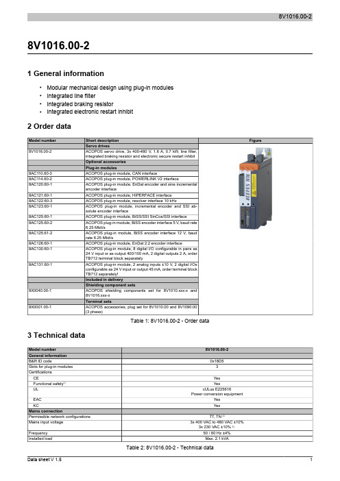
8V1016.00-21 General information•Modular mechanical design using plug-in modules•Integrated line filter•Integrated braking resistor•Integrated electronic restart inhibit2 Order dataTable 1: 8V1016.00-2 - Order data 3 Technical dataTable 2: 8V1016.00-2 - Technical data1)Achievable safety classifications (safety integrity level, safety category, performance level) are documented in the user's manual (section "Safety technology").2)In the USA, TT and TN power mains are commonly referred to as "Delta/Wye with grounded Wye neutral".3)If the module is operated with a mains input voltage of 3x 230 VAC, then automatic nominal voltage detection doesn't work for the DC bus. The UDC_NOMINALparameter must be set to 325 [V] by the user in this case.4)Limit values from EN 61800-3 C3 (second environment).5)The permissible input voltage range is reduced when using motor holding brakes. The input voltage range should be selected so that the proper supplyvoltage for the motor holding brake can be maintained.6)The current requirements depend on the configuration of the ACOPOS servo driveThe inrush current is significantly higher than the value for current consumption and can be estimated according to the input capacitance.7)Valid in the following conditions: 400 VAC mains input voltage, nominal switching frequency, 40°C ambient temperature, installation elevation <500 m abovesea level.8)Value for the nominal switching frequency.9)If necessary, the stress of the motor isolation system can be reduced by an additional externally wired dv/dt choke. For example, the RWK 305 three-phasedv/dt choke from Schaffner () can be used. Important: Even when using a dv/dt choke, it is necessary to ensure that an EMC-compatible, low inductance shield connection is used!10)The module's electrical output frequency (SCTRL_SPEED_ACT * MOTOR_POLEPAIRS) is monitored to protect against dual use in accordance with ECregulation 428/2009 | 3A225. If the electrical output frequency of the module exceeds the limit value of 598 Hz uninterrupted for more than 0.5 s, then the current movement is aborted and error 6060 is output (Power element: Limit speed exceeded).11)OSSD (output signal switching device) signals are used to monitor signal lines for short circuits and cross faults.12)Continuous operation of ACOPOS servo drives at elevations ranging from 500 m to 2000 m above sea level is possible (taking the specified continuouscurrent reductions into consideration).13)Continuous operation of ACOPOS servo drives at ambient temperatures ranging from 40°C to max. 55°C is possible (taking the specified continuous currentreductions into consideration), but this will result in a shorter service life.4 Status indicatorsACOPOS servo drives are equipped with three LEDs for direct diagnostics:Figure 1: ACOPOS servo drive indicatorsDescriptionSolid green The module is operational andpresent and booted, no permanent or temporary errors).Blinking green 1)The module is not ready for operation.Examples:•No signal on one or both enable inputs•DC bus voltage outside the tolerance range•Overtemperature on the motor (temperature sensor)•Motor feedback not connected or defective•Motor temperature sensor not connected or defective•Overtemperature on the module (IGBT junction, heat sink, etc.)•Disturbance on networkSolid orange The module's power stage is enabled.Solid red 1)There is a permanent error on the module.Examples:•Permanent overcurrent•Invalid data in EPROMTable 3: ACOPOS servo drive - LED status indicators1)Firmware V2.130 and later.If no LED is lit up, the ACOPOS servo drive is not supplied with 24 VDC mains voltage.Danger!After switching off the device, wait for the DC bus to discharge for at least five minutes. To avoid a hazard, the current voltage on the DC bus must be measured with a suitable measuring instrument and less than 42 VDC before starting work. An unlit operating LED does not indicate that the device is de-energized!4.1 Status changes when starting up the operating system loaderThe following intervals are used for the LED status indicators:Width of box: 125 msRepeats after: 3000 msTable 4: Status changes when starting up the operating system loaderTable 5: Error status with reference to CAN plug-in module AC1101)Possible errors:- The ACOPOS servo drive is defective.- The plug-in module is defective- The plug-in module is not connected properly in the slot.Table 6: Error status with reference to POWERLINK V2 plug-in module AC114 1)Possible errors:- The ACOPOS servo drive is defective (plug-in module not detected).- The plug-in module is defective- The plug-in module is not connected properly in the slot.- The plug-in module works but is not automatically detected by the ACOPOS servo drive (old bootstrap loader).5 Dimension diagram and installation dimensionsHanging verticallyFigure 2: Dimension diagram and installation dimensions1)For proper air circulation, at least 80 mm clearance must be available above and below the ACOPOS servo drive. Approximately 100 mm clearance isrequired under the ACOPOS servo drive to prevent cabling problems.6 WiringPinout overviewFigure 3: ACOPOS 1010, 1016 - Pinout overview6.1 X1 - PinoutTable 7: X1 - Pinout1)The wiring is not permitted to exceed a total length of 30 m.Information:To obtain a defined reference of ground to ground potential, B&R recommends grounding the COM connections (5-7, 14, 15) on connector X1.6.2 X2 - PinoutTable 8: X2 - Pinout6.3 X3 - PinoutTable 9: X3 - Pinout6.4 X4a, X4b - PinoutTable 10: X4a - Pinout1)If the holding brake is connected via an additional external relay contact (ground-in e.g. via connections S1/S2) instead of only via the internal transistor, thenthe internal quenching circuit has no effect! In this case, the customer must make sure that neither the relay contact nor the braking coil are damaged when switching off the brake. This can be done by interconnecting the coil or - better still - interconnecting the contact with a quenching circuit.Table 11: X4b - Pinout1)If the holding brake is connected via an additional external relay contact (ground-in e.g. via connections S1/S2) instead of only via the internal transistor, thenthe internal quenching circuit has no effect! In this case, the customer must make sure that neither the relay contact nor the braking coil are damaged when switching off the brake. This can be done by interconnecting the coil or - better still - interconnecting the contact with a quenching circuit.Danger!The connections for the motor temperature sensors and the motor holding brake are safely isolated circuits. These connections are therefore only permitted to be connected to devices or components that have sufficient isolation per IEC 60364-4-41 or EN 61800-5-1.Caution!If B+ and B- are swapped when connecting the permanent magnet holding brakes, then the brakes cannot be opened! ACOPOS servo drives cannot determine if a holding brake is connected with reverse polarity!6.4.1 Wiring the connections for the motor holding brakeThe power supply, enabling and monitoring of the output for the motor holding brake can be carried out in three different ways via the wiring of connector X4a:Table 12: Enabling the external holding brake1)The two jumpers are already wired on connector X4a supplied with ACOPOS servo drives.2)External dry contacts can be connected between S1 and S2 and between S3 and S4. This makes it possible to enable the holding brake via external safetycircuits independently of the control integrated in the ACOPOS servo drive.3)Configuration takes place using ParID 90 (1 ... Internal monitoring active, 5 ... Internal monitoring not active).4)Disabling takes place using ParID 90 (5 ... Internal monitoring not active).8V1016.00-2 6.5 X5 - PinoutTable 13: X5 - Pinout6.6 Additional protective ground connection (PE)The protective ground conductor is connected to the M5 threaded bolt provided using a cable lug.Terminal cross sectionsCable lug for M5 threaded boltTable 14: Protective ground connection (PE) - ACOPOSDanger!Before turning on the servo drive, make sure that the housing is properly connected to ground (PE rail).The ground connection must be established even when testing the drive or operating it for a short time!8V1016.00-26.7 Input/output circuit diagramFigure 4: TriggerFigure 5: LimitFigure 6: Enable8V1016.00-2Figure 7: Input/output circuit diagram - ACOPOS 1010, 1016。
※多功能低压交流伺服驱动器※KYDAS48300-1E使用手册(V2.0)济南科亚电子科技有限公司目录一.概述 (4)1、型号说明 (4)2、产品规格 (5)3、技术参数 (6)二.安装尺寸图 (7)1、平板散热 (7)2、风冷散热 (8)三.端口接线说明 (9)(1)、接线定义 (9)(2)、接口说明 (10)(3)、接线图 (12)(4)、配套线束(长0.5m) (12)四.操作说明 (13)1.上位机软件说明 (13)1.1.配置说明 (13)1.2.软件使用说明 (13)1.3.参数功能说明 (15)2.指示灯说明 (17)2.1.状态指示灯(蓝色) (17)2.2.故障指示灯(红色) (17)3.CAN指令说明 (18)3.1.通用配置 (18)3.2.指令说明 (19)3.3.CAN总线控制示例 (21)4.串口指令说明 (24)4.1.通用配置 (24)4.2.控制格式 (24)4.3.查询格式 (25)4.4.串口心跳数据 (28)五.故障保护与复位 (29)1.故障保护依据 (29)2.故障信息列表 (29)使用警告:1、初次使用应先进行相位DANGER确认,待确认相序无误后才能进行正常操作。
2、在接线有误等情况下操作电机旋转时,电机会因相位不正确而停转并发热,若持续时间过长会烧坏电机,此时应尽快关闭驱动器电源。
一.概述1、型号说明2、产品规格3、技术参数二.安装尺寸图1、平板散热注意:驱动器周围需要保留接线空间,建议>10cm、风冷散热2进风口注意:驱动器周围需要保留接线空间(建议>15cm),及良好的通风环境。
三.端口接线说明(1)、接线定义35PIN 定义1S3S32S1S13TMP-MI电机温度4+5V5Vout5F/R换向6EN使能7FLASH程序短接点8R2R29RC RC信号输入10RX-SA232—RX11JUP1120R+12CAN-L CAN-L端13编码器A-增量编码器A-14编码器B+增量编码器B+ 15编码器Z-增量编码器Z-16霍尔V+霍尔信号V+(HB+) 17SIN模拟量信号输入18GND0V19S4S420R1R121TX-SA232—TX22JUP2120R-23CAN-H CAN-H端24编码器A+增量编码器A+ 25编码器B-增量编码器B-26编码器Z+增量编码器Z+ 27霍尔U+霍尔信号U+(HA+) 28霍尔W+霍尔信号W+(HC+) 29GND0V30S2S231+5V5Vout32GND0V33+5V1RC电源34OUT数字输出35I5GND信号地(RC、232)(2)、接口说明①、TX-SA,RX-SA,I5GND:RS232通讯接口,实现指令控制,以及参数设置、运行状态调测等;另7脚FLASH与GND短接后,可用此接口烧写程序;②、CAN-H,CAN-L:CAN2.0通讯接口∙ 当11(JUP1)和22(JUP2)外部短接时,内部120R终端电阻接通;③、SIN:模拟输入接口。
永磁同步电机控制系统使用说明书
上海电驱动有限公司
1 电机控制系统的组成该电机控制系统的应用范围:电动车
图1-1 电机控制器
2 注意事项!!!
·电机控制器只能用来控制专门配置的电机。
·电机控制器工作输入电压范围:DC 250V-420V,输入电压上限450VDC,禁止超过输入的电压上限。
·电机控制系统使用循环水冷却,严禁在无冷却的条件下带载运行或长时间空载运行;同时,水冷循环系统必须满足电机和电机控制器对于冷却的要求。
·位置传感器的信号传输距离≤2米,超出此距离系统则无法保证正常工作。
·电机控制器的外部接线,要求严格按照本说明书一一对应。
·当该套电机控制系统用于台架试验时,直流电源功率(大功率直流电源柜或电池组)必须与控制系统的电参数相匹配。
·固定动力母线的螺钉若有损坏,必须使用随机配带的螺钉进行更换。
3 电机控制系统电气原理图
图3-1 电机控制系统电气原理图
4 电机控制器外部接口及接线示意图
图4-1 电机控制器对外接口
信号线
电机三相电源
图4-2 电机控制器与电池组接线示意图
图4-3 电机控制器与电机接线示意图
5 电机控制系统外部接插件定义及其示意图电机控制系统外部接插件机械图见附件:北汽外部线束图。
xb430永磁机构驱动器说明书
XB430永磁机构驱动器说明书
一、引言
XB430永磁机构驱动器是一种用于驱动永磁机构的电子设备。
本说明书将详细介绍XB430永磁机构驱动器的结构、特点、使用方法和维护保养等内容,旨在帮助用户正确、安全地使用该设备。
二、结构与特点
1. 结构
XB430永磁机构驱动器由电源模块、驱动模块、控制模块和保护模块组成。
电源模块负责为驱动器提供稳定的电源,驱动模块通过控制信号驱动永磁机构的运动,控制模块负责接收用户的指令并将其转化为相应的控制信号,保护模块则负责对驱动器进行过流、过压等保护。
2. 特点
(1)高效能:XB430永磁机构驱动器采用先进的电路设计,具有高效能的特点,能够提供稳定的驱动功率,使永磁机构运转更加稳定、高效。
(2)高可靠性:驱动器采用可靠性较高的元件和材料制造而成,能够在各种恶劣的工作环境下保持稳定的性能,具有较高的抗干扰能力。
(3)多种保护功能:驱动器内置多种保护功能,如过压保护、过流保护、过热保护等,能够有效保护驱动器和永磁机构的安全运行。
三、使用方法
1. 连接电源:将XB430永磁机构驱动器的电源模块与电源连接,确保供电稳定。
2. 连接控制信号:将控制模块与控制信号源连接,确保控制信号的准确传递。
3. 连接永磁机构:将驱动模块与永磁机构连接,确保驱动信号能够准确传递给永磁机构。
4. 设置参数:根据实际需要,通过控制模块设置驱动器的参数,如驱动功率、运行模式等。
5. 启动驱动器:根据实际需要,通过控制模块启动驱动器,使其开始对永磁机构进行驱动。
6. 监控运行状态:在驱动器工作期间,通过控制模块可以实时监控驱动器和永磁机构的运行状态,如转速、温度等。
四、维护保养
1. 定期清洁:定期对XB430永磁机构驱动器进行清洁,去除灰尘和污垢,保持设备通风良好。
2. 定期检查:定期检查各个模块的连接状态,确保连接可靠;检查电源模块的电源线路,确保电源供应正常。
3. 注意防护:在使用过程中,要注意防护措施,避免发生碰撞、摔落等意外情况,以免损坏驱动器和永磁机构。
4. 注意温度:在使用过程中,要注意驱动器和永磁机构的温度,避免过热,影响设备的正常运行。
五、常见问题与解决方法
1. 驱动器无法启动:检查电源连接是否正常,确认电源供应稳定;检查控制信号是否正确传递,确认控制信号源正常。
2. 驱动器无法工作稳定:检查驱动模块与永磁机构的连接是否松动,确认连接可靠;检查驱动模块的参数设置是否正确,调整参数以达到稳定工作的要求。
3. 驱动器发热过高:检查驱动器的通风情况,确保设备通风良好;检查驱动功率是否过大,适当降低驱动功率。
六、总结
本说明书详细介绍了XB430永磁机构驱动器的结构、特点、使用方法和维护保养等内容。
用户在使用该驱动器时,应根据本说明书的指导,正确、安全地操作设备,以确保驱动器和永磁机构的正常运
行。
如有其他疑问或故障,可及时与生产厂家联系,寻求技术支持。