GMW15373_Nov 2007 Specification for Electronic Throttle Control (ETC) Accelerator Pedal Component
- 格式:pdf
- 大小:602.52 KB
- 文档页数:29

Customer Specification PART NO. 7132ConstructionApplicable Specifications Environmental Alpha Wire | 711 Lidgerwood Avenue, Elizabeth, NJ 07207 Tel: 1-800-52 ALPHA (25742), Web: Diameters (In)1) Component 1 1 X 1 HOOKUPa) Conductor 20 (7/28) AWG TC 0.038b) Insulation 0.016" Wall, Nom. PVC, Irradiated 0.070+/- 0.002(1) Print ALPHA WIRE-*E163869 RU AWM 1430 105C 300V VW-1LLXXXXXX CSA REW XLPVC 105C 300V FT1 ROHS* = Factory Code[Note: Product may have c(UL) or CSA markings depending upon plant of manufacture.](2) Color(s) WHITE, BLACK, RED, GREEN, YELLOW, BLUE, BROWN ORANGE, SLATE, VIOLET1) UL AWM/STYLE 1430 105°C / 300 V RMS2) CSA International REW-XLPVC 105°C / 300 V RMSFT13) Military MIL-W-16878E Type C 105°C / 1000 V RMS1) EU Directive 2011/65/EU(RoHS2):All materials used in the manufacture of this part are in compliance withEuropean Directive 2011/65/EU regarding the restriction of use of certainhazardous substances in electrical and electronic equipment. Consult AlphaWire's web site for RoHS C of C.PropertiesOther2) REACH Regulation (EC 1907/2006):This product does not contain Substances of Very High Concern (SVHC)listed on the European Union's REACH candidate list in excess of 0.1%mass of the item. For up-to-date information, please see Alpha's REACH SVHC Declaration.3) California Proposition 65:The outer surface materials used in the manufacture of this part meet the requirements of California Proposition 65.Physical & Mechanical Properties 1) Temperature Range -55 to 105°C 2) Bend Radius 10X Cable Diameter 3) Pull Tension 8.7 Lbs, MaximumElectrical Properties (For Engineering purposes only) 1) Voltage Rating 300 V RMS 2) Inductance 0.05 µH/ft, Nominal3) Conductor DCR 10.1 Ω/1000ft @20°C, NominalPackaging Flange x Traverse x Barrel (inches)a) 1000 FT 6.5 x 4 x 2.5 Continuous length b) 100 FT2.75 x 2 x 1.125 Continuous length[Spool dimensions may vary slightly]Notes:a) Certain colors and put-up combinations may only be available by special order, minimums may apply.Alpha Wire | 711 Lidgerwood Avenue, Elizabeth, NJ 07207Tel: 1-800-52 ALPHA (25742)Although Alpha Wire (“Alpha”) makes every reasonable effort to ensure there accuracy at the time of publication,information and specifications described herein are subject to errors or omissions and to changes without notice, and the listing of such information and specifications does not ensure product availability.Alpha provides the information and specifications herein on an “AS IS” basis, with no representations or warranties, whether express, statutory or implied. In no event will Alpha be liable for any damages (including consequential, indirect, incidental, special, punitive, or exemplary) whatsoever, even if Alpha had been advised of the possibility of such damages, whether in an action under contract, negligence or any other theory, arising out of or in connection with the use, or inability to use, the information or specifications described herein.ALPHA WIRE - CONFIDENTIAL AND PROPRIETARYNotice to persons receiving this document and/or technical information. This document is confidential and is the exclusive property of ALPHA WIRE, and is merely on loan and subject to recall by ALPHA WIRE at any time. By taking possession of this document, the recipient acknowledges and agrees that this document cannot be used in any manner adverse to the interests of ALPHA WIRE, and that no portion of this document may be copied or otherwise reproduced without the prior written consent of ALPHA WIRE. In the case of conflicting contractual provisions, this notice shall govern the status of this document. <br /><br />©2019 ALPHA WIRE - all rights reserved.EU/China ROHS CERTIFICATE OF COMPLIANCETo Whom It May Concern:Alpha Wire Part Number: 71327132, RoHS-Compliant Commencing With 6/1/2005 ProductionNote: all colors and put-upsThis document certifies that the Alpha part number cited above is manufactured in accordance with Directive 2011/65/EU of the European Parliament, better known as the RoHS Directive (commonly known as RoHS 2), with regards to restrictions of the use of certain hazardous substances used in the manufacture of electrical and electronic equipment. This certification extends to amending Directive 2015/863/EU which expanded the list of restricted substances to 10 items (commonly known as RoHS 3) The reader is referred to these Directives for the specific definitions and extents of the Directives. No Exemptions are required for RoHS Compliance on this item. Additionally, Alpha certifies that the listed part number is in compliance with China RoHS “Marking for Control of Pollution by Electronic Information Products” standard SJ/T 11364-2014.Substance Maximum Control ValueLead0.1% by weight (1000 ppm)Mercury0.1% by weight (1000 ppm)Cadmium0.01% by weight (100 ppm)Hexavalent Chromium0.1% by weight (1000 ppm )Polybrominated Biphenyls (PBB)0.1% by weight (1000 ppm)Polybrominated Diphenyl Ethers (PBDE) ,Including Deca-BDE0.1% by weight (1000 ppm)Bis(2-ethylhexyl) phthalate (DEHP)0.1% by weight (1000 ppm)Butyl benzyl phthalate (BBP)0.1% by weight (1000 ppm)Dibutyl phthalate (DBP) 0.1% by weight (1000 ppm)Diisobutyl phthalate (DIBP)0.1% by weight (1000 ppm)The information provided in this document and disclosure is correct to the best of Alpha Wire's knowledge, information and belief at the date of its release. The information provided is designed only as a general guide for the safe handling, storage, and any other operation of the product itself or the one that it will become part of. The intent of this document is not to be considered a warranty or quality specification. Regulatory information is for guidance purposes only. Product users are responsible for determining the applicability of legislation and regulations based on their individual usage of the product.Authorized Signatory for the Alpha Wire:Dave Watson, Director of Engineering & QA1/13/2021Alpha Wire711 Lidgerwood Ave.Elizabeth, NJ 07207Tel: 1-908-925-8000。

AC/DC Co nverterRAC05-K/PD3/H5 Watt2‘‘ x 1‘‘Single OutputREACHcompliantRoHS 2+compliant10 from 10IEC/EN62368-1 compliant UL61010-1 certified (4)CSA C22.2 No. 61010-1 certified (4)IEC/EN61010-1 certified IEC/EN61204-3 compliant EN55032 compliant EN55014-1 compliant EN55014-2 compliant EN55024 compliant EN61000 compliant CB ReportSelection GuidePart Input Output Output Efficiency Max. CapacitiveNumber Voltage Range Voltage Current typ (1)(2)[VAC] [VDC] [mA] [%] [µF]RAC05-05SK/PD3/H 90-3185 1000 73 10000 RAC05-12SK/PD3/H 90-318 12 420 74 1200On RequestRAC05-15SK/PD3/H 90-31815330741000Notes:Note1: Efficiency is tested at 277VAC and full load at +25°C ambient Note2: Max Cap Load is tested at nominal input and full resistive loadModel NumberingOrdering Examples:RAC05-05SK/PD3/H 5Vout Single Output RAC05-12SK/PD3/H 12VoutSingle OutputS inglenom. Output PowerOutput VoltageRAC05-__ _K/PD3/H5003727BASIC CHARACTERISTICSParameterConditionMin.Typ.Max.Nominal Input Voltage 50/60Hz 100VAC 277VAC Operating Range (3)47-63Hz 90VAC277VAC318VAC Absolute Maximum Input Voltage (4)528VAC Input Current 100VAC 277VAC 110mA 60mAInrush Currentcold start at +25°C20ANo load Power Consumption 500mWMinimum Load0%Specifications (measured @ Ta= 25°C, 277VAC, full load and after warm-up unless otherwise stated)E470721DescriptionThe RAC05-K/PD3/H series of 5 watt AC/DC are IE C61010 safety rated to PD3 and OVCIII by UL for 100-277VAC nominal input lines (-10/+15%). The modules support an operating temperature range from -40°C to +85°C in harsh environments with a possible excessive increase in the input conditions up to 400Vac / 480Vac, permanently without damage. Fully protected outputs as well as EMC class A and B compliance without external components for floating installations. All these features make them an ideal fit for integration into smart grid, renewable energy, smart metering and IoT applications.3Notes:Note3: Refer to …Line Derating“Note4: UL61010-1 valid for Input Range 90-318VAC onlySpecifications (measured @ Ta= 25°C, 277VAC, full load and after warm-up unless otherwise stated)Specifications (measured @ Ta= 25°C, 277VAC, full load and after warm-up unless otherwise stated)PROTECTIONSParameter Type Value Input Fuse (6)external slow blow 350VAC, 2A Limited Power Source (LPS)according to IEC62368-1 CB Report Short Circuit Protection (SCP)below 100m W hiccup, automatic restart Over Voltage Protection (OVP)150% - 195%, hiccup mode Over Voltage Category OVC III Over Current Protection (OCP)150% - 195%, hiccup mode Class of Equipment Class IIENVIRONMENTALParameter Condition ValueOperating Temperature Range@ natural convection 0.1m/s 5Voutfull load-40°C to +70°C refer to …Derating Graph“-40°C to +80°C 12Voutfull load-40°C to +80°C refer to …Derating Graph“-40°C to +85°CMaximum Case Temperature+100°C Temperature Coefficient0.05%/K Thermal Impedance 0.1m/s16K/W Operating Altitude5000m Pollution Degree PD3 Operating Humidity non-condensing5% - 95% RH max.Vibration according to MIL-STD-202G 10-500Hz, 2G 10min./1cycle, period 60min. each along x,y,z axesDesign Lifetime +25°C+60°C105 x 103 hours40 x 103 hoursMTBF according to MIL-HDBK-217F, G.B.+25°C+40°C>1726 x 103 hours>1585 x 103 hoursSpecifications (measured @ Ta= 25°C, 277VAC, full load and after warm-up unless otherwise stated)SAFETY AND CERTIFICATIONSCertificate Type (Safety)Report Number StandardAudio/video, information and communication technology equipment - Safety requirements (LVD)200811140GZU-001IEC62368-1:2014, 2nd EditionEN62368-1:2014 + A11:2017Safety requirements for electrical equipment for measurement, control and laboratory use - Part 1: General requirements E470721UL61010-1CAN/CSA C22.2 No. 61010-1Safety requirements for electrical equipment for measurement, control and laboratory use -Part 1: General requirements190415125GZU-001EN61010-1:2010Safety requirements for electrical equipment for measurement, control and laboratory use -Part 1: General requirements (CB Scheme)IEC61010-1:2010 + A1:2016 3rd Edition EAC RU-AT.03.67361TP TC 004/020, 2011 RoHS2RoHS-2011/65/EU + AM-2015/863 EMC Compliance Condition Standard / CriterionLow-voltage power supplies DC output - Part 3: Electromagnetic compatibilityLCS180508025BE IEC/EN61204-3:2018, Class BElectromagnetic compatibility of multimedia equipment – Emission Requirements (8)EN55032:2015, Class B Electromagnetic compatibility of household appliances, electric tools and similar apparatus- Emission RequirementsEN55014-1:2006+A2:2011 Information technology equipment - Immunity characteristics - Limits and methods ofmeasurementEN55024:2010+A1:2015 Electromagnetic compatibility of household appliances, electric tools and similar apparatus- Immunity RequirementsEN55014-2:2015ESD Electrostatic discharge immunity test Air: ±15, 8, 4, 2kVContact: ±8, 4, 2kVEN61000-4-2: 2009, Criteria ARadiated, radio-frequency, electromagnetic field immunity test 10V/m, 80MHz-1GHz3V/m, 1.5GHz-2GHz1V/m, 2GHz-2.7GHzEN61000-4-3: 2006 + A1:2009, Criteria AFast Transient and Burst ImmunityAC In Port: ±2.0kVDC Out Port: ±2.0kVEN61000-4-4:2012, Criteria ASurge Immunity AC IN Port: L-N ±4.0kVDC Out Port: ±0.5kVEN61000-4-5:2014+A1:2017, Criteria AImmunity to conducted disturbances, induced by radio-frequency fields10Vrms EN61000-4-6:2014, Criteria A Power Magnetic Field Immunity50Hz, 30A/m EN61000-4-8:2010, Criteria ASpecifications (measured @ Ta= 25°C, 277VAC, full load and after warm-up unless otherwise stated)EMC Compliance Condition Standard / CriterionVoltage Dips and InterruptionsDips 100%Dips 60, 30, 20%Interruptions > 95%EN61000-4-11:2004+A1:2017, Criteria BEN61000-4-11:2004+A1:2017, Criteria CEN61000-4-11:2004+A1:2017, Criteria CLimits of Voltage Fluctuations & Flicker EN61000-3-3:2013 Notes:Note8: If output is connected to GND, please contact RECOM tech support for advicePACKAGING INFORMATIONParameter Type Value Packaging Dimension (LxWxH)tube490.0 x 56.0 x 40.0mm Packaging Quantity15pcs Storage Temperature Range-40°C to +85°C Storage Humidity non-condensing20% to 90% RH max.The product information and specifications may be subject to changes even without prior written notice.The product has been designed for various applications; its suitability lies in the responsibility of each customer. The products are not authorized for use in safety-critical applications without RECOM’s explicit written consent. A safety-critical application is an application where a failure may reasonably be expected to endanger or cause。

Eaton 167706Eaton Moeller series xEffect - FRCmM-NA RCCB. Residual currentcircuit breaker (RCCB), 40A, 4p, 30mA, type G/A, UL, 110VGeneral specificationsEaton Moeller series xEffect - FRCmM-NA RCCB167706FRCMM-40/4/003-G/A-NA-110401508164247280 mm71 mm70 mm0.32 kg RoHS conformUL 1053ÖVE E 8601 IEC/EN 61008 EN45545-2 IEC 61373Additionally protects against special forms of residual pulsating DC which have not been smoothed.Product Name Catalog NumberModel CodeEAN Product Length/Depth Product Height Product Width Product Weight Compliances Certifications Catalog Notes40 AIs the panel builder's responsibility. The specifications for the switchgear must be observed.7035-35 °CMeets the product standard's requirements.Is the panel builder's responsibility. The specifications for the switchgear must be observed.DIN railQuick attachment with 2 latch positions for DIN-rail IEC/EN 6071540 ADoes not apply, since the entire switchgear needs to be evaluated.0.03 A100 V AC - 210 V AC, 94 V AC - 132 V AC (UL)Meets the product standard's requirements.Short time-delayed8 ms delay at 60 Hz10 ms delay at 50 HzInterlocking device500 A eaton-rcd-application-guide-br019003en-en-us.pdfUL 1053 DIN Rail RCCBEaton's Volume 4—Circuit Protectioneaton-xeffect-industrial-switchgear-range-catalog-ca003002en-en-us.pdf eaton-xeffect-frcmm-na-rccb-catalog-ca003019en-en-us.pdfDA-DC-03_FRCmeaton-circuit-breaker-xeffect-frcmm-na-rccb-dimensions.epsMA180503312DA-CD-f9_ul1053_4pDA-CS-f9_ul1053_4pEaton Specification Sheet - 167706eaton-circuit-breaker-xeffect-frcmm-rccb-wiring-diagram-002.eps eaton-xeffect-frcmm-rccb-wiring-diagram-002.jpgRated operational current for specified heat dissipation (In) 10.11 Short-circuit ratingRAL-numberPermitted storage and transport temperature - min10.4 Clearances and creepage distances10.12 Electromagnetic compatibilityMounting MethodAmperage Rating10.2.5 LiftingRated fault current - maxTest circuit range10.2.3.1 Verification of thermal stability of enclosures Tripping timeFitted with:Rated residual making and breaking capacity Application notesBrochuresCatalogsCertification reports DrawingsInstallation instructions mCAD model Specifications and datasheets Wiring diagramsFrequency rating50 Hz / 60 Hz10.8 Connections for external conductorsIs the panel builder's responsibility.Fault current rating30 mATerminal protectionFinger and hand touch safe, DGUV VS3, EN 50274Special featuresFRCmM-NA-110Residual current circuitbreakersType G/A (ÖVE E 8601)Sensitivity typePulse-current sensitiveAmbient operating temperature - max40 °CHeat dissipation per pole, current-dependent3.275 WClimatic proofing25-55 °C / 90-95% relative humidity according to IEC 60068-2Built-in depth70.5 mmShort-circuit ratingMax. admissible back-up fuse: 63 A gG/gL, 70 A class J fuse (UL)FeaturesResidual current circuit breakerAdditional equipment possibleLifespan, electrical4000 operationsTerminal capacity (cable)M5 (with cross-recessed screw as defined in EN ISO 4757-Z2, PZ2)Connectable conductor cross section (solid-core) - min1.5 mm²Contact position indicator colorRed / green10.9.3 Impulse withstand voltageIs the panel builder's responsibility.Number of polesFour-poleTerminal capacity (solid wire)1.5 mm² - 35 mm²Ambient operating temperature - min-25 °C10.6 Incorporation of switching devices and componentsDoes not apply, since the entire switchgear needs to be evaluated.Rated short-circuit strength5 kA (UL, as per CSA)10 kA with back-up fuse10.5 Protection against electric shockDoes not apply, since the entire switchgear needs to be evaluated.Used withFRCmM-NA-110Type G/A (�VE E 8601)Residual current circuit breakersMounting positionAs requiredEquipment heat dissipation, current-dependent13.1 W10.13 Mechanical functionThe device meets the requirements, provided the information in the instruction leaflet (IL) is observed.10.2.6 Mechanical impactDoes not apply, since the entire switchgear needs to be evaluated.10.9.4 Testing of enclosures made of insulating materialIs the panel builder's responsibility.ApplicationSwitchgear for 110-V systems10.3 Degree of protection of assembliesDoes not apply, since the entire switchgear needs to be evaluated.Voltage rating (IEC/EN 60947-2)110/190 VVoltage typeACTerminal capacity (stranded cable)16 mm² (2x)Leakage current typeAFrame45 mmBuilt-in width (number of units)70 mm (4 SU)Terminals (top and bottom)Lift terminalsAmbient humdity range5 - 95 %Impulse withstand current3 kA (8/20 μs) surge-proofWidth in number of modular spacings410.2.3.2 Verification of resistance of insulating materials to normal heatMeets the product standard's requirements.10.2.3.3 Resist. of insul. mat. to abnormal heat/fire by internal elect. effectsMeets the product standard's requirements.Lifespan, mechanical10000 operationsStatus indicationWhite / blue10.9.2 Power-frequency electric strengthIs the panel builder's responsibility.Connectable conductor cross section (solid-core) - max35 mm²Degree of protectionIP20, IP40 with suitable enclosureIP20Rated short-time withstand current (Icw)10 kAOvervoltage tested - max530 VPollution degree210.7 Internal electrical circuits and connectionsIs the panel builder's responsibility.Connectable conductor cross section (multi-wired) - min 1.5 mm²Rated impulse withstand voltage (Uimp)4 kV10.10 Temperature riseThe panel builder is responsible for the temperature rise calculation. Eaton will provide heat dissipation data for the devices.FunctionsShort-time delayed trippingVoltage rating (UL)208/120 V, 60 HzConnectable conductor cross section (multi-wired) - max 16 mm²TypeCurrent test marks as perinscriptionMaximum operatingtemperature is 75 °C:Starting at 40 °C, the max.permissible continuouscurrent decreases by 2.5%for every 1 °CThe maximum operatingcurrent of back-up fuse mustnot exceed the residualcurrent circuit breaker'srated operational current10.2.2 Corrosion resistanceMeets the product standard's requirements.10.2.4 Resistance to ultra-violet (UV) radiationMeets the product standard's requirements.10.2.7 InscriptionsMeets the product standard's requirements.Eaton Corporation plc Eaton House30 Pembroke Road Dublin 4, Ireland © 2023 Eaton. All Rights Reserved. Eaton is a registered trademark.All other trademarks areproperty of their respectiveowners./socialmedia3 kA60 °C40 A gG/gL0.03 A 22 mA190 V440 VSurge current capacity Permitted storage and transport temperature - max Admissible back-up fuse overload - max Rated fault current - min Pick-up current Rated operational voltage (Ue) - max Rated insulation voltage (Ui)。
REVISED: 09.17.2020MSL = N/A: Not ApplicablePbR o HS/RoHS II C omplaint Electrical SpecificationsFEATURESAPPLICATIONSParametersMin.Typ.Max.Units NoteFrequency Range32.000080.0000MHz Standard Available Frequencies 32.0000, 37.4000, 38.4000, 40.0000, 45.0000, 48.0000, 52.0000, 60.0000,76.8000, 80.0000MHzContact Abracon for Nonstandard FrequenciesOperation ModeFundamentalOperating Temperature Range -40+85°C See Options Storage Temperature-40+125°C Frequency Tolerance @ +25°C -10+10ppm See options Frequency Stability over the Operating Temperature ( ref. to +25°C)-15+15ppmSee options Equivalent series resistance (R1)(over -40°C to +125°C) at 5pF plating load*< 45100Ω32.0000-32.9999MHz< 358033.0000-36.9999MHz < 255037.0000-80.0000MHzShunt capacitance (C0) 1.0pF Load capacitance (CL) 5.0pF See options Drive Level 10100μW Aging (1 year)-2+2ppm @25°C± 3°C Insulation Resistance500MΩ@100 Vdc ± 15V• World’s smallest At-Cut MHz Crystal (1.20 x 1.00 x 0.33 mm package)• Ideally suited for space constraint IoT, Wearables & Wireless applications• Simultaneously optimized for low plating load & ESR over extended temperature range• Enhanced performance for start-up time and power savings with Low Energy SoC’s• Low profile ideal for height constraint designs • Available with ±10 ppm set-tolerance• Wearables• Wireless Modules• Internet of Things (IoT)• Bluetooth / Bluetooth Low Energy (BLE)• Machine-to-Machine (M2M) Connectivity • Ultra-Low Power MCU’s, SoC’s, Transceivers • Near Field Communication •ISM Band Applications(*) Plating Load = Load Capacitance (CL)REVISED: 09.17.2020MSL = N/A: Not ApplicablePbR o HS/RoHS II C omplaint Options and Part IdentificationCustom ESR if other than standard R □□: Specify a value in Ω (e.g.: R40)ABM13W-MHz -Frequency in MHz Please specify the Frequency in MHz out to 4 digit accuracy after the decimal.(e.g. 32.0000MHz)Load Capacitance(pF)8: 8pF 7: 7pF 6: 6pF 5: 5pFOperating Temp.B: -20°C ~ +70°C N: -30°C ~ +85°C D: -40°C ~ +85°C J: -40°C ~ +105°C K: -40°C ~ +125°CFreq. Tolerance H7: ± 7 ppm 1: ± 10 ppm 7: ± 15 ppm 2: ± 20 ppmFreq. Stability U: ± 10 ppm (*)G: ± 15 ppm (**)X: ± 20 ppm (**)Y: ± 30 ppm (***)Z: ± 50 ppmPackaging Blank: Bulk T5: 5kpcs / reelNote 1:Contact Abracon for part number requests with carrier frequency callouts up to 5 & 6 digit accuracy after the decimal.(*) Only offered @ Operating Temp. Range options: B & N (**) Only offered @ Operating Temp. Range options: B, N, & D (***) Only offered @ Operating Temp. Range options: B, N, D, & J Contact ABRACON for tighter Frequency Stability options.[Note 1]Pb R o HS/RoHS II C omplaintMSL = N/A: Not Applicable Typical Frequency vs. Temperature Characteristics (ref. to +25°C):Typical ESR (Equivalent Series Resistance) vs. Temperature Characteristics:REVISED: 09.17.2020Pb R o HS/RoHS II C omplaintMSL = N/A: Not Applicable SPICE Models (based on typical values at 25ºC ± 3ºC):Typical Frequency Tolerance Distribution (at 25ºC ± 3ºC):REVISED: 09.17.2020Pb R o HS/RoHS II C omplaintMSL = N/A: Not Applicable Typical ESR Distribution (at 25ºC ± 3ºC):REVISED: 09.17.2020MSL = N/A: Not ApplicablePb R o HS/RoHS II C omplaint Mechanical DimensionsDimensions: mmPin #2: GND (Electrically connected to metallic package lid)Pin #4: NC (No internal connection, leave floating or connectto GND)Recommended Land PatternTop ViewBottom ViewREVISED: 09.17.2020REVISED: 09.17.2020MSL = N/A: Not ApplicablePbR o HS/RoHS II C omplaint Reflow ProfileZone Description Temperature Time 1Preheat / Soak T SMIN ~ T SMAX 160±10°C80 ~ 100 sec.2Reflow T L 220°C 50 ~ 70 sec. 3Peak heatT P260±5°C5 sec. MAX.T pT LT LT pT SMINT SMAX Ramp UpRamp DownCritical ZoneT L to T p231Time25PreheatT e m p e r a t u r ePb R o HS/RoHS II C omplaintMSL = N/A: Not Applicable Packaging:T5: Tape and reel (5,000pcs/reel)Dimensions: mmATTENTION:Abracon LLC’s products are COTS – Commercial-Off-The-Shelf products; suitable for Commercial, Industrial and, where designated, Automotive Applica-tions. Abracon’s products are not specifically designed for Military, Aviation, Aerospace, Life-dependant Medical applications or any application requiring high reliability where component failure could result in loss of life and/or property. For applications requiring high reliability and/or presenting an extreme operating environment, written consent and authorization from Abracon LLC is required. Please contact Abracon LLC for more information.REVISED: 09.17.2020。
ROTATING VANE ANEMOMETER ALNOR® MODEL RVA801AIRFLOW™ INSTRUMENTSMODEL LCA301OPERATION AND SERVICE MANUALP/N AFL9021485, REV CNOVEMBER 2014CopyrightTSI Incorporated / 2007-2014 / All rights reserved.AddressTSI Incorporated / 500 Cardigan Road / Shoreview, MN 55126 / USA Fax No.(651) 490-3824Limitation Of Warranty And Liability (effective April 2014)(For country-specific terms and conditions outside of the USA, please visit .)Seller warrants the goods, excluding software, sold hereunder, under normal use and service as described in the operator's manual, to be free from defects in workmanship and material for 24 months, or if less, the length of time specified in the operator's manual, from the date of shipment to the customer. This warranty period is inclusive of any statutory warranty. This limited warranty is subject to the following exclusions and exceptions:a. Hot-wire or hot-film sensors used with research anemometers, andcertain other components when indicated in specifications, are warranted for 90 days from the date of shipment;b. Pumps are warranted for hours of operation as set forth in product oroperator’s manuals;c. Parts repaired or replaced as a result of repair services are warranted tobe free from defects in workmanship and material, under normal use, for90 days from the date of shipment;d. Seller does not provide any warranty on finished goods manufactured byothers or on any fuses, batteries or other consumable materials. Only the original manufacturer's warranty applies;e. This warranty does not cover calibration requirements, and sellerwarrants only that the instrument or product is properly calibrated at the time of its manufacture. Instruments returned for calibration are not covered by this warranty;f. This warranty is VOID if the instrument is opened by anyone otherthan a factory authorized service center with the one exception where requirements set forth in the manual allow an operator to replaceconsumables or perform recommended cleaning;g. This warranty is VOID if the product has been misused, neglected,subjected to accidental or intentional damage, or is not properlyinstalled, maintained, or cleaned according to the requirements of the manual.Unless specifically authorized in a separate writing by Seller,Seller makes no warranty with respect to, and shall have no liability inconnection with, goods which are incorporated into other products orequipment, or which are modified by any person other than Seller.The foregoing is IN LIEU OF all other warranties and is subject to the LIMITATIONS stated herein. NO OTHER EXPRESS OR IMPLIEDiiiWARRANTY OF FITNESS FOR PARTICULAR PURPOSE OR MERCHANTABILITY IS MADE. WITH RESPECT TO SELLER’S BREACH OF THE IMPLIED WARRANTY AGAINST INFRINGEMENT, SAID WARRANTY IS LIMITED TO CLAIMS OF DIRECT INFRINGEMENT AND EXCLUDES CLAIMS OF CONTRIBUTORY OR INDUCED INFRINGEMENTS. BUYER’S EXCLUSIVE REMEDY SHALL BE THE RETURN OF THE PURCHASE PRICE DISCOUNTED FOR REASONABLE WEAR AN D TEAR OR AT SELLER’S OPTION REPLACEMENT OF THE GOODS WITH NON-INFRINGING GOODS. TO THE EXTENT PERMITTED BY LAW, THE EXCLUSIVE REMEDY OF THE USER OR BUYER, AND THE LIMIT OF SELLER'S LIABILITY FOR ANY AND ALL LOSSES, INJURIES, OR DAMAGES CONCERNING THE GOODS (INCLUDING CLAIMS BASED ON CONTRACT, NEGLIGENCE, TORT, STRICT LIABILITY OR OTHERWISE) SHALL BE THE RETURN OF GOODS TO SELLER AND THE REFUND OF THE PURCHASE PRICE, OR, AT THE OPTION OF SELLER, THE REPAIR OR REPLACEMENT OF THE GOODS. IN THE CASE OF SOFTWARE, SELLER WILL REPAIR OR REPLACE DEFECTIVE SOFTWARE OR IF UNABLE TO DO SO, WILL REFUND THE PURCHASE PRICE OF THE SOFTWARE. IN NO EVENT SHALL SELLER BE LIABLE FOR LOST PROFITS, BUSINESS INTERRUPTION, OR ANY SPECIAL, INDIRECT, CONSEQUENTIAL OR INCIDENTAL DAMAGES. SELLER SHALL NOT BE RESPONSIBLE FOR INSTALLATION, DISMANTLING OR REINSTALLATION COSTS OR CHARGES. No Action, regardless of form, may be brought against Seller more than 12 months after a cause of action has accrued. The goods returned under warranty to Seller's factory shall be at Buyer's risk of loss, and will be returned, if at all, at Seller's risk of loss.Buyer and all users are deemed to have accepted this LIMITATION OF WARRANTY AND LIABILITY, which contains the complete and exclusive limited warranty of Seller. This LIMITATION OF WARRANTY AND LIABILITY may not be amended, modified or its terms waived, except by writing signed by an Officer of Seller.Service PolicyKnowing that inoperative or defective instruments are as detrimental to TSI as they are to our customers, our service policy is designed to give prompt attention to any problems. If any malfunction is discovered, please contact your nearest sales office or representative, or call Customer Service department at +44 (0) 149 4 459200 (UK), (800) 874-2811 (USA), or (1) 651-490-2811 (International).ivSECTION 1General DescriptionThe RVA801/LCA301 is intended for measurement of air velocity and volume flow at return grilles, fume hoods, kitchen exhausts, etc. It features a 180-degree rotating head which functions satisfactorily in the 0o and 180o positions. This allows the LCD display to be viewed from the front of the instrument while the head is oriented with the flow direction.In addition, the instrument measures the temperature of the air flow.SECTION 2SafetyObserve common sense safety precautions when using the RVA801/LCA301. Exercise care to ensure that the instrument does not interfere with any moving equipment or electrical wiring. This instrument is not designed for gas mixtures other than air. Use with explosive and/or other dangerous gas mixtures is not recommended and is at the user’s own risk.-5-SECTION 3About the RVA801/LCA301 Installing the BatteryThe RVA801/LCA301 requires a 9-volt battery. The battery is not installed when the instrument is shipped. Remove the battery cover by pressing on the two lines and sliding downwards. Connect the battery to the flying lead, insert the battery into the instrument and replace the battery cover.LCD displayThe instrument will display the velocity, volume or temperature reading as selected.Auto Shut OffThe RVA801/LCA301 has an auto shut off feature to help preserve battery life. If no keys are pressed for 3 minutes (5 minutes in temperature mode), the instrument will automatically turn itself off. This function cannot be disabled by the user.-6-SECTION 4Detailed OperationPress the ON\OFF key to turn theRVA801/LCA301 on and off. When the instrument is turned on, it will power up in the mode last used.Mode key On/ Off keyEnglish/Metric Unit SelectionRVA801/LCA301 instruments can display Metric or Imperial units. To select metric or imperial units, press the Mode key while turning on the-7-unit. Then press the trigger to select the unit type and press the Mode key again to save your setting.Measuring Air VelocitySelect velocity using the MODE key if required. In order to take a velocity reading, hold the rotating vane in the airstream noting the flow direction arrow on the instrument head. Keep the vane in the airstream for about five seconds before pressing the trigger key to take a reading. This enables the vane anemometer to reach steady speed and the average reading will be more accurate.To take a single reading, press the trigger key momentarily. The instrument will display the measured value.Press and hold the trigger key to take a sweep, or time-averaged, reading. The sweep reading will update approximately every second. Release the trigger key to stop the sweep measurement and display the average value.Measuring Air VolumeThe operation for air volume measuring is the same as air velocity. To calculate air volume, the air velocity and area (duct, grille size or Air Cone data) are required. The RVA801/LCA301 rotating vane anemometer allows the user to-8-enter the area into the instrument and get direct volume flow readings.To measure air volume, determine the cross-sectional area of the duct or grille for which the volume flow rate is required. If working in metric units, calculations must be in m2. If working in Imperial units, calculations must be in ft2. Switch the instrument to “Area +” mode and observe the area figure displayed from the memory. If the new area required is larger than the one displayed press the trigger to increase the displayed area to the calculated figure. If the area is less than the figure displayed push the Mode Button to change to “Area -” mode and press the trigger to reduce the displayed area to the calculated figure. When the correct area has been displayed use the Mode key to select the required “Vol” mode.Low Battery IndicationWhen the "BAT" icon appears, theRVA801/LCA301 has about 60 minutes of battery life remaining. If the battery is not replaced, measurement accuracy will decrease.-9-Serial Number DisplayThe instrument’s serial number can be verified by holding both the trigger and mode key when switching the unit on.SECTION 5Care, Maintenance and Service Please return the Product Registration Card immediately. This allows us to send service reminders, special offers, and important information about your product.∙Remove batteries from instrument if not used for an extended period of time.∙Do not bend or touch blades; accuracy will be affected.∙Do not immerse in liquids.∙Do not drop the instrument.∙Use carrying case for storage, transport, and protection from dust.∙Use a clean damp cloth to wipe theinstrument case. Do not wipe the blades. Service Return ProcessReturn the RVA801/LCA301 for service in case the instrument was dropped, blades were-10-deformed, or liquid spilled on the instrument, particularly the blades.Before sending your instrument for calibration or repair, obtain a Return Material Authorization (RMA) number by visiting our website at or contacting customer service. When obtaining an RMA number, you will also learn the cost of service or calibration and receive shipping instructions.Appendix AVolume Flow Rate MeasurementsUsing Air ConesIf Air Cones are used to measure the volume flow rate, the area entered in the instrument needs to be related to the 100 mm vane diameter.The correct value to be entered can be found in the Air Cone manual that comes with the cones (see side pocket of the carrying case).-11--12-The following sticker can be found on the latest Air Cone offerings:-13-(This page intentionally left blank)-14-MODEL RVA801/LCA301SPECIFICATIONS(subject to change without notice) Measurement RangeVelocity50 to 6000 fpm0.25 to 30 m/s Temperature 40 to 113 °F 5 to 45 °CVolumetric Flow Rate 1-9999000 cfm 1 - 999999 l/s1 - 999999 m3/h0.01 – 3000 m3/sArea Input0.043 - 900 ft20.00399 - 90 m2 Actual range is a function of velocity and area input. Display ResolutionVelocity 1 fpm0.01 m/s Temperature 1 °F0.1 °C AccuracyVelocity±1% reading ±4fpm ±1% reading ±0.02 m/sTemperature±2 °F±1 °CStorageTemperature-4 to 140 °F-20 to 60 °COperatingTemperature40 to 113 °F 5 to 45 °C Power Source 9-volt batteryBattery Life Approximately 40 hours continuoususeDimensions (LWD) 11 in. ⨯ 4.5 in. ⨯2.6 in.280 mm ⨯ 112mm ⨯ 65 mmWeight 10 oz.275 g (excluding battery)Alnor Products, TSI Incorporated Visit our website for more information.Airflow Instruments, TSI Instruments Ltd.Visit our website at for more information.USA Tel: +1 800 874 2811 UK Tel: +44 149 4 459200 India Tel: +91 80 67877200France Tel: +33 491 11 87 64 China Tel: +86 10 8219 7688Germany Tel: +49 241 523030 Singapore Tel: +65 6595 6388P/N AFL9021485 Rev. C ©2014 TSI Incorporated Printed in U.S.A.The Observator range is in continuous development and so specifications may be subject to change without prior notice.Welcome to the world of ObservatorSince 1924 Observator has evolved to be a trend-setting developer and supplier in a wide variety of industries. Originating from the Netherlands, Observator has grown into an internationallyoriented company with a worldwide distribution network and offices in Australia, Germany, the Netherlands,Singapore and the United Kingdom.We represent this supplier. For more information contactObservator Instruments:T: +31 (0)180 463411 E:*******************Rietdekkerstraat 62984 BM RidderkerkThe Netherlands。
■Model Encoding / Order Information■DescriptionSafety: UL/EN/IEC 60950-1 EMC: EN 55022 / 55024Factory control or automation apparatus Test and measurement instrument Laser related machine Burn-in facility RF application■Features■Certificates■ApplicationsUniversal AC input / Full range Built-in active PFC function High efficiency up to 92%Forced air cooling by built-in DC fanOutput voltage and current programmableBuilt-in remote ON-OFF control / remote sense / auxiliary power DC OK signal/ Protections: Short circuit / Overload / Over voltage/ Over temperatureOptional conformal coating 5 years warrantySeries nameOutput wattage Output voltage (5V/12V/15V/24V/27V/48V)RSP-750 is a 750W single output enclosed type AC/DC power supply. This series operates for 90~264VAC input voltage and offers the models with the DC output mostly demanded from the industry. Each model is cooled by the built-in fan with fan speed control, working for the temperature up to 70. Moreover, RSP-750 ℃provides vast design flexibility by equipping various built-in functions such as the output programming, remote ON-OFF control, auxiliary power, etc.5DimensionL2509.84W 127H 41(1U)(1U)mminch1.61******Fig 3.1External Voltage (2~5.5VDC)External Voltage (2~5.5VDC)Fig 4.1+S 1357+VS 248-S PV -VS PSDC_OK 12V-AUXPC CN50CN50PO GND GND 1311G-AUX 14◎If EXTERNAL VOLTAGE (VDC) <0.5V,the power supply may enter under voltage protection; it needs to be restarted to work.EXTERNAL VOLTAGE (VDC)EXTERNAL VOLTAGE (VDC)1122334455.555.566PV(Referenced to GND)PC(Referenced to GND)100110100110120120Vout Io OVP 120%(Typ.)Io 115%(Typ.)Non-LinearNon-LinearUVP 10%(Typ.)8080606040402020O U T P U T V O L T A G E (%)O U T P U T C U R R E N T (%)+S 5711+VS 6-S PV -VS PSDC_OK 12V-AUXPC POGND GND 13G-AUX 141324※In addition to the adjustment via the built-in potentiometer, the output voltage can be trimmed to 40~110% of the nominal voltage by applying EXTERNAL VOLTAGE.3. Output Voltage Programming (or, PV / remote voltage programming / remote adjust / margin programming / dynamic voltage trim)4. Output Current Programming (or, PC / remote current programming / dynamic current trim)※The output current can be trimmed to 40~110% of the rated current by applying EXTERNAL VOLTAGE.※Caution: By factory default, the Output Current Programming is not activated, and and are shorted by connector. Whenever thisPC(pin7)PO(pin8)function is not needed to activate, as assumed in other sections’diagrams, please keep and shorted ; otherwise, the PC(pin7)PO(pin8)power supply will have no output.※Caution: By factory default, the Output Voltage Programming is not activated, and and are shorted by connector. Whenever thisPV (pin5)PS(pin6)function is not needed to activate, as assumed in other sections’diagrams, please keep and shorted ; other wise, the PV (pin5)PS(pin6)power supply will have no output.TB1CN50+V-V LOAD -+113214REMOTEON-OFF REMOTEON-OFFFig 5.1+S1357911+VS2468-S PV -VS PSDC_OK 12V-AUXPC CN50POGND GND 13G-AUX 145.DC_OK signal"DC_OK" is an open collector signal. It indicates the output status of the power supply. It can operate in two ways : One is sinking current from external ※TTL signal ; the other is sending out a TTL voltage signal.The maximum sink current is 10mA and the maximum external voltage is 5.6V.Sinking current from external TTL signal:◎◎Sending out TTL voltage signal :Between and DC- OK(pin9)GND(pin10&11)0 ~ 1V 3.3 ~ 5.6VOutput Status Power supply ON Power supply OFFREMOTEON-OFF TB1CN50+V-V LOAD -+113214。
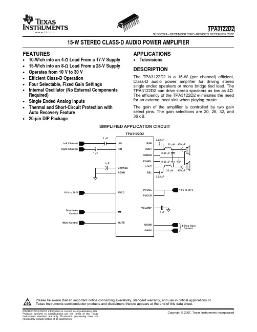
Specification for Electronic Throttle Control (ETC) Accelerator PedalComponent© Copyright 2007 General Motors Corporation All Rights ReservedNovember 2007 Originating Department: North American Engineering StandardsPage 1 of 291 IntroductionNote: Nothing in this standard supersedes applicable laws and regulations.Note: In the event of conflict between the English and domestic language, the English language shall take precedence.1.1 Scope. This is the Component Technical Specification for all General Motors (GM) applications with electronic throttle control (ETC). 1.2 Mission/Theme. This document provides supplier requirements with the intent that GM be provided a World Class Accelerator Pedal Mechanism (APM). The APM is the major interface between the Driver and the Engine Management System.1.3 Classification.1.3.1 Terminology. Specialized terminology will be included in the Glossary (6.1) of this document. 1.4 Document Management.1.4.1 Change Management. This document is the responsibility of the GM Engineering and revisions will be made by their staff via appropriate change management processes.1.5 Contact/Owner. Total Integration Engineer (TIE) Accelerator and Clutch Apply.2 ReferencesNote: Only the latest approved standards are applicable unless otherwise specified. 2.1 External Standards/Specifications. ASTM A228 SAE J826 ASTM A1000 SAE J1395 CMVSS 124 SAE J1885 FMVSS 1242.2 GM Standards/Specifications.9985687 GMW3100 GM4486P GMW3103 GM6015M GMW3116 GM9328P GMW3205 GMN10200D GMW7293GMW3001 GMW14151 GMW3059 GMW14551 GMW3091 GMW15152 GMW3094 GMW15272 GMW3097 GMW15335 2.3 Additional References. GM1724 GM1738 GM1797 PQS 15-200RADC-TR-84-2443 Requirements3.1 System/ Subsystem/ Component/ Part Definition.3.1.1 Appearance.3.1.1.1 Appearance by Design. The Accelerator Pedal Mechanism shall have a visual appearance of black (reference 848 Black although pedals may be allowed 2 to 3 times standard tolerance) and/or silver in color. Painted surfaces shall have no cracking, peeling or runs. No supplier Logo shall appear on the outside of part. Final appearance approval shall be made by GM Engineering.3.1.1.2 Appearance after Durability. Portions of the Accelerator Pedal Mechanism visible from below the lower Dash Panel area appearance shall not degrade, and wear on the pedal pad foot surface shall be less than 0.5 mm after exposure to SAE J1885, or any vehicle or component test referenced in this specification. 3.1.2 Content.3.1.2.1 Physical Content.3.1.2.1.1 Housing, Lever, Lever Return Springs,Hysteresis Mechanism, Sensor, Shields/Guards. The APM shall consist of: Housing, Lever, two or more return springs, hysteresis provider, two independent pedal position sensors outputs, and shields/guards to prevent contamination and/or loose interior components (screws, hoses, wires, etc) from hindering pedal operation.GMW15373 GM WORLDWIDE ENGINEERING STANDARDS© Copyright 2007 General Motors Corporation All Rights ReservedPage 2 of 29 November 20073.1.2.1.1.1 Return Springs. At least two (2) of the APM return springs shall have a wire diameter difference of at least 0.10 mm, each produced using completely different tooling including cutoffs. Differentiated springs shall be physically error proofed to prevent installation in the same unit. Each spring shall be designed for infinite life with a stress level that shall not exceed 65% for torsion springs or 45% for compression springs. The spring material shall be ASTM A228 (music wire), ASTM A1000 (Chromium Silicon), or of higher quality. Under no circumstance shall an acid wash process be used on the springs.3.1.2.1.2 Sensor Lube. Sensor lube if used shall be certified for acceptable performance with minimum and maximum tolerance quantities applied and all environments stated in section 3.1.3.1.3.1.2.1.3 Sensor Springs.3.1.2.1.3.1 Disconnected Sensor Return Capability. If the pedal position sensing assembly can be removed from the APM, or secure connection to the pedal lever can be compromised, while continuing to produce potentially valid outputs, the sensor shall have a return spring that will force the Position Output to or lower than the APM output at the Idle Stop as specified in 3.2.1.5. 3.1.2.1.3.2 Number of Sensor Return Springs. The sensor shall have two (2) springs if worse case analysis and/or testing indicates, when the first spring is severed or disconnected mechanism lash/compliance could occur that results in requirements of 3.2.1.5 being exceeded. Reference CMVSS 124 and FMVSS 124 single severance or disconnection requirements.3.1.2.1.4 Mounting Provisions and Pedal Pad. See program specific Component Technical Specification (CTS)3.1.2.2 Functional Content. The Accelerator Pedal Mechanism shall perform the following primary functions:• Provide accelerator pedal position feedback to the driver’s foot, i.e.; load and hysteresis. • Convert angular rotation of the pedal lever to proportional changes in electrical sensor outputs. 3.1.3 Ambient Environment.3.1.3.1 Operational Environment. The APM shall meet all operational performance requirements (Reference 3.2.1), without loss of functions or degradation of service life, when exposed to the following environments. The Electronic Throttle Control Subsystem shall not exhibit any undesirable operating modes when the APM is subjected to environments within and outside those listed below. Undesired operating modes include in-range incorrect driver intent output or any other deviation from Performance requirements stated in 3.2.1. When constructing a program specific CTS refer to the Vehicle Technical Specification (VTS) for program specific environments.3.1.3.1.1 Temperature. The APM at any time during service life shall meet requirements when exposed to:• Air Temperature (at component location) -40°C to + 66°C.3.1.3.1.2 Pressure. The APM at any time during service life shall meet requirements when exposed to:• Atmosphere Pressure (absolute) 57 kPa to 106 kPa.3.1.3.1.3 Chemicals.3.1.3.1.3.1 Humidity. The APM at any time during service life shall meet requirements when exposed to:• Relative Humidity: 0% to 100%.3.1.3.1.3.2 General Contaminants. The APM at any time during service life shall meet requirements when exposed to cleaners, fluids and contaminants specified in Table 1.3.1.3.1.3.3 Road Contaminants. The APM at any time during service life shall meet requirements when exposed to road contaminants specified in Table 2.3.1.3.1.3.4 Ozone. The APM at any time during service life shall meet requirements when exposed to ozone concentrations and durations specified in Table 3.3.1.3.1.4 Particulates. Tables 3 thru 5 list particulates that the Accelerator Pedal Mechanism may see repeated exposure during its service life.GM WORLDWIDE ENGINEERING STANDARDS GMW15373© Copyright 2007 General Motors Corporation All Rights ReservedNovember 2007 Page 3 of 29Table 1: General ContaminantsContaminant ContentComponent Exposure Area Power Steering Fluid Available at GM dealer or from Mr. Goodwrench website. Visible from Drivers foot area Automatic Trans Fluid Dextron III or equivalent,Visible from Drivers foot area Brake FluidDOT 3 or other available from Mr. GoodwrenchEntire Assembly Windshield Washer Fluid Available at GM dealer or from Mr. Goodwrench website. Entire AssemblyEngine coolant Available at GM dealer or from Mr. Goodwrench website. Visible from Drivers foot area Choke Cleaner Available at GM dealer or from Mr. Goodwrench website. Visible from Drivers foot area 5% Salt/Water Solution 5% salt by weightEntire AssemblyGM Surface Engine Cleaner Available at GM dealer or from Mr. Goodwrench website. Visible from Drivers foot area Tire Cleaner Whitewall Available at GM dealer or from Mr. Goodwrench website. Visible from Drivers foot area Tar Remover Available at GM dealer or from Mr. Goodwrench website. Visible from Drivers foot area Injector Cleaner Available at GM dealer or from Mr. Goodwrench website. Visible from Drivers foot area Clean Water TapEntire AssemblyCarburetor Cleaner Available at GM dealer or from Mr. Goodwrench website. Visible from Drivers foot area Engine Degreaser Available at GM dealer or from Mr. Goodwrench website. Visible from Drivers foot area Engine Oil Commercially available 15W30 Motor Oil Visible from Drivers foot area Synthetic Motor Oil Commercially available 15W30Synthetic Motor Oil Visible from Drivers foot area Road Tar OilAvailable at GM dealer or from Mr. Goodwrench website.Visible from Drivers foot area Axle & Manual Transmission LubricantsGear Oil Available at GM dealer or from Mr. Goodwrench website. Visible from Drivers foot area Multipurpose Grease Available at GM dealer or from Mr. Goodwrench website. Visible from Drivers foot area Lithium Grease Available at GM dealer or from Mr. Goodwrench website.Visible from Drivers foot area Battery Electrolyte Reagent-grade sulfuric acid, diluted w/water to specific gravity, 1.25 to 1.28Visible from Drivers foot area Unleaded Gasoline Commercially available Visible from Drivers foot area Solvent (Naphtha) Commercially available Visible from Drivers foot area Diesel Fuel Commercially availableVisible from Drivers foot area Carpet Cleaner Available at GM dealer or from Mr. Goodwrench website. Entire Assembly Hydraulic FluidAvailable at GM dealer or from Mr. Goodwrench website. Entire Assembly Biological (Mold, Fungus) GM9328PEntire Assembly Coffee Commercially available Entire Assembly ColaCommercially available Entire Assembly Alcohol Base Cleanser GM6015M (10 % by volume) Entire Assembly Ammonia Base Cleanser Commercial (10 % by volume) Entire Assembly Vinyl Plasticizers Armorall or equivalentEntire Assembly Hand CleanserAvailable at GM dealer or from Mr. Goodwrench website.Entire AssemblyGMW15373 GM WORLDWIDE ENGINEERING STANDARDS© Copyright 2007 General Motors Corporation All Rights ReservedPage 4 of 29 November 2007Table 2: Road ContaminatesContaminant Content In-passengerCompartmentWater H 2O X Snow/Ice Frozen Water XCalcium Chloride CaClX Sodium ChlorideNaCl - Salt (non-Iodized)X De-icing & Dust Control (Calcium Magnesium Acetate - CMA or Calcium Lignosulfonate) Per Contaminant XAcid Rain 62% Sulfuric, 32% Nitric, and 6% Hydrochloric acids at a pH of 3.0 and 4.0 XRoad Tar, Oil9985687X (See Note 1)Note 1: For Portions of the component below the Lower Dash Close-Out Panel. Note: Some contaminates may come through a leaky Front Of Dash or HVAC unit.Table 3: Ozone ContaminatesTime - at ambient temperature and ozone concentrationTotal Time: 10 years = 87 600 Hours for Pass Cars, 12 years = 105 120 Hours for TrucksTotal Ozone Exposure: 27 700 PPM for Passenger Cars, 33324 PPM for Trucks Location: Los Angeles, CaliforniaTemp (°C)Ozone concentration (PPM) 0.00 0.01 to 0.05 0.06 to 0.10 0.11 to 0.15 0.16 to 0.20 0.21 to 0.25 0.26 to 0.30 0.31 to 0.35 0.36 to 0.40% Total Vehicle Life % Total TimeIn Band38 to 43 0.01 0.07 0.08 0.08 0.07 0.02 0.02 0.01 0.01 0.35 32 to 38 0.07 0.72 0.97 0.74 0.56 0.29 0.09 0.02 0.01 3.46 27 to 32 0.92 3.32 3.03 2.34 1.13 0.35 0.07 0.01 0 11.18 21 to 27 4.53 8.97 4.44 1.23 0.17 0.01 0 0 0 19.38 16 to 21 10.23 16.02 1.07 0.01 0 0 0 0 0 27.34 10 to 16 10.73 14.25 0.03 0 0 0 0 0 0 25.01 4 to 10 4.82 7.32 0 0 0 0 0 0 0 12.13 -1 to 4 0.38 0.76 0 0 0 0 0 0 0 1.14 Total 31.70 51.43 9.62 4.40 1.93 0.67 0.17 0.03 0.01 100 Source: Purchaser Validation Center, Product Usage Measurements and Application, Los Angeles Area Ozone DataTable 4: ParticulatesContaminant ContentIn-passenger Compartment (C)Dirt, Grit, and Sand See Table 5X Mud Various % of water w/Dirt, Grit and sand. X DustSee Table 5XTable 5: Sand and Dust Exposure TimesExposure Time of Sand and Dust that the APM may see repeated exposure during its service lifeConcentration mg/m 3Exposure Time (hours)70 74.5 350 25.0 1600 5.0 3900 1.0GM WORLDWIDE ENGINEERING STANDARDS GMW15373© Copyright 2007 General Motors Corporation All Rights ReservedNovember 2007 Page 5 of 293.1.3.1.5 Methods of Pedal Release. The Accelerator Pedal Mechanism may see repeated exposure to the following operator pedal pad release conditions during its service life: • Gentle (very slow, <1 mm/s). • Sidestep (instantaneous release).• Release speeds between gentle and sidestep. 3.1.3.1.6 Driver Applied Forces. The APM, as installed in vehicle, shall meet requirements when exposed to the following operator applied load conditions to any point on the accelerator pedal pad during its service life:• 668 N (150 lb) force in pedal apply direction. • 178 N (40 lb) force in the upward direction. • 178 N (40 lb) force in both lateral directions. • 556 N (125 lb) force 45 degrees each side from normal in the horizontal plane.3.1.3.1.7 Vehicle Deceleration. The APM at any time during service life shall meet requirements when exposed to the following vehicle decelerations:• 1.5G vehicle decelerations. 3.1.3.1.8 Spray Washes.3.1.3.1.8.1 Washes at Cold Temperature. The APM at any time during service life shall meet requirements when exposed to Spray wash with 1200 minimum psi nozzle pressure sprayer with a flow rate of at least 2.6 gallons per minute (GPM) at a distance of 50 mm in a sweeping motion to simulate cleaning over portions of the pedal visible from the foot well area using 25°C water for 5 s when the component is at -7°C, then soaked at -40°C for at least 8 h.3.1.3.1.8.2 Washes at Warm Temperature. The APM at any time during service life shall meet requirements when exposed to Spray wash with 1200 minimum psi nozzle pressure sprayer with a flow rate of at least 2.6 GPM at a distance of 50 mm in a sweeping motion to simulate cleaning over portions of the pedal visible from the foot well area using 10 ± 5°C water for 5 s when the component is at 50°C.3.1.3.1.9 Impact. The APM at any time during service life shall meet requirements when exposed 200 impacts with a steel vacuum cleaner nozzle (0.2 kg moving at 0.3 m/s) to any portion of the APM which is 50 mm or more below the lower dash panel.3.1.3.1.10 Vibration All components in the pedal subsystem shall be designed to withstand the levels of vibration that occurs during vehicle at their respective location. Tables 6, 7, and 8 are typicaldirection power spectral density profile for a dash mounted component merged from a range of vehicles. The Pedal subsystem shall withstand 50 h of exposure to this environment on each axis without degradation or creating noise.Table 6: Vertical Vibration ProfileFrequency (hertz) Accel ((m 2/s 4)/Hz)8.00 0.300 11.00 8.300 15.00 0.320 19.00 3.700 22.00 0.170 24.00 4.100 31.00 0.025 38.00 0.290 43.00 0.011 48.00 0.203 50.00 0.010 67.00 0.010 71.00 0.085 74.00 0.020 100.00 0.020 RMS 6.3Table 7: Fore-Aft Vibration ProfileFrequency (hertz) Accel ((m 2/s 4)/Hz)8 0.500 11 1.010 14 0.109 20 6.370 28 0.079 38 1.550GMW15373 GM WORLDWIDE ENGINEERING STANDARDS© Copyright 2007 General Motors Corporation All Rights ReservedPage 6 of 29 November 2007Frequency (hertz) Accel((m 2/s 4)/Hz)60 0.020 100 0.020 RMS 5.3Table 8: Lateral Vibration ProfileFrequency (hertz) Accel ((m 2/s 4)/Hz)8 0.300 11 3.100 17 0.190 20 2.870 26 0.039 38 0.075 54 0.010 100 0.010 RMS 4.23.1.3.1.11 Voltage. The APM shall utilize 5 volt regulated reference voltages, 0 to 5 volt outputs, and 0.0 volt returns.3.1.3.1.12 Electromagnetic Compatibility. The APM at any time during service life shall meet requirements when exposed to EMC environments per GMW3091, GMW3094, GMW3097, and GMW3100.3.1.3.1.13 Radiation3.1.3.1.13.1 Total Solar Radiation. The APM at any time during service life shall meet requirements when exposed to 18 500 g*cal/cm 2 (775 MJ/m 2) per year.3.1.3.1.13.2 Ultraviolet Radiation. The APM at any time during service life shall meet requirements when exposed to 826 g*cal/cm 2 (34.6 MJ/m 2) per year. Ultraviolet radiation is defined as wavelengths between 295 and 385 nm. 3.1.3.2 Extreme Operating Environment (On Vehicle). The APM shall meet specified extremeenvironmental operational performance requirements listed in 3.2.1. The APM shall not exhibit any permanent failure modes or undesired operating modes when subjected to extreme environments listed below. Undesired operating modes include incorrect driver intent output.3.1.3.2.1 Extreme Temperature. The following range encompasses the extreme temperatures that the APM may be exposed to during its service life: • -54 to 85°C.3.1.3.2.2 Extreme Pressure. The following range encompasses the extreme pressures that the APM may be exposed to during its service life:• 20 to 106.3 kPa.3.1.3.2.3 Extreme Loads. The APM as installed in vehicle may be exposure to the following operator applied load conditions to any point on the accelerator pedal pad during its service life:• 1113 N (250 lb.) force in pedal apply direction. 3.1.3.2.4 Extreme Voltage. The Accelerator Pedal Module may be exposed to +16 volts for 1 h applied to any connector pin, or housing due to electrical system shorts or servicing.3.1.3.3 Manufacturing/Shipping Environment. The APM shall not exhibit any permanent failure modes or undesirable operating modes after being subjected to manufacturing environments that include Component Shipping, and Vehicle Assembly & Shipping. Undesired operating modes include incorrect driver intent output.3.1.3.3.1 Temperature. The following range encompasses the temperatures that the Accelerator Pedal Mechanism may be exposed to at the vehicle assembly or sub-assembly plant; or during shipping:• Air Temperature 65 to + 48°C.3.1.3.3.2 Pressure. The following range encompasses the pressures that the APM may be exposed to at the vehicle assembly or sub-assembly plant, or during shipping:• Atmosphere Pressure (absolute) 20 to 106 kPa. 3.1.3.3.3 Loads.3.1.3.3.3.1 Point. The APM, not installed, may be exposed 334 N (75 lb) in the pedal apply direction applied anywhere on Pedal Pad.3.1.3.3.4 Impact. The following value encompasses the characteristics of mishandling that APM may be exposed to at the vehicle assembly or sub-assembly plant:• Impact exposure equivalent to being dropped one meter onto a concrete surface. 3.1.4 Interfaces.3.1.4.1 External-to-Vehicle to Subsystem The APM will have the following driver interfaces: • Driver right foot to accelerator pedal.• Five (5) to 95 percentile male and female extremes Driver foot sizes (including Big Foot), heel point, hip point, and reach shall be considered in the design of the APM.3.1.4.2 Subsystem to Subsystem. (More interface information is provided in 3.7.2.)GM WORLDWIDE ENGINEERING STANDARDS GMW15373© Copyright 2007 General Motors Corporation All Rights ReservedNovember 2007 Page 7 of 293.1.4.2.1 ETC System to APM. APM shall be compatible to all of the ETC Systems intended to be used with this vehicle. See 3.2.1 for specific requirements.3.1.4.2.2 Front of Dash (FOD) or Mod Plate or Brake/Accel/Clutch Pedal Module Assembly to APM.3.1.4.2.2.1 Mounting Provisions. The APM shall mount to the FOD or Mod Plate or Brake/Accel/Clutch Pedal Module Assembly being designed for the specified vehicle.3.1.4.2.2.2 Overload Forces. The APM shall be designed to prevent driver applied loads causing excessive stress to the FOD or Mod Plate or Brake/Accel/Clutch Pedal Module Assembly.3.1.4.2.3 Electrical Connector to APM. The APM and Vehicle Electrical Harness shall be compatible. See 3.7.2.2.2 and 3.7.2.2.3 for specific requirements.3.1.5 Usage Definition.3.1.5.1 Minimum Expected Service Life. The service life of the Electronic Throttle Control Accelerator Pedal Module shall be at least; 161 000 km (100 000 mi) or 10 years working life (9000 h ignition on) for passenger car applications, 150 000 miles or 12 years working life (12 000 h ignition on) for light duty truck applications, and 322 000 km (200 000 mi) or 15 years working life (15 000 h ignition on) for heavy duty truck applications.3.1.5.2 Minimum Typical Predicted Usage Profile. The APM (with lever and pad in place) may be subjected to the following apply and retract cycles. These environments are thought to represent a 99.8 percentile usage customer. Some customers will be more severe.3.1.5.2.1 Instantaneous Release. One thousand (1000) instantaneous releases from the maximum displacement position3.1.5.2.2 Dithers. Twenty five million (25 000 000) dithers/50 000 000 sensor direction changes (which may contribute to wiper fatigue and increased sensor wear) consisting of at least 3% Vref sensor displacement from the idle position.3.1.5.2.3 General Durability. General durability: greater than 815 000 applications of various displacements greater than or equal to 10% for an Automatic Transmission Passenger Vehicle, 1.6 million for a Manual Transmission Passenger Vehicle, 1.2 million for a Automatic Transmission 4WD Light Duty Truck, 2.4 million for a Manual Transmission 4WD Light Duty Truck. SpecificGMW14551 cycle equivalence estimations can beprovided by the Pedal TIE. 3.2 Product Characteristics.3.2.1 Performance Requirements. The APM shall meet all performance requirements as stated herein with at least ± 3δ capability when subjected to Environments (3.1.3), Interfaces (3.1.4) and Usage (3.1.5) unless otherwise specified within this document. Techniques utilized to satisfy the performance requirements will be reviewed by and approved by GM.3.2.1.1 CMVSS 124 and FMVSS 124 Compliance. The vehicle Electronic Throttle Control System shall comply with the requirements of FMVSS 124 and CMVSS 124 effective at the time of vehicle manufacturer. Thus the APM shall comply to sections 3.1.2.1 Physical Content, 3.2.1.2 Return Response Time, 3.2.1.5.1.2 APM Output Requirements at the Idle Stop, 3.2.1.5.8 Disconnected Sensor Return Capability, 3.2.1.5.10 Sensor Drive Mechanism Lash/compliance, and other requirements stated within this document regarding returning to idle. 3.2.1.2 Return Response.3.2.1.2.1 Initial Return Response Time. The Initial Return Response Time when production part approval process (PPAP) intent pedals are tested per GMW15152 shall be less than 100 ms for temperatures at and above -18°C and less than 150 ms for temperatures at and between -18 and -40°C (or the minimum operational temperature as specified in the VTS), with all energy return forces, and with each disconnected. Initial Return Response Time is defined as the time from release of force from the pedal pad to the first time when the Pedal Sensor Outputs are within the Idle Position output specifications. Reference Table 9 and Table 10 Accelerator Pedal Parameters.3.2.1.2.2 Pedal Output Bounce. The first Pedal Sensor Output "Bounce" following a side step maneuver (instantaneously releasing the pedal from Full Travel Stop and the lever bouncing of the idle stop) when PPAP intent pedals are tested per GMW15152 shall result in peak Pedal Sensor Outputs of (S1Bounce - S1Idle ) / (ΔS1) ≤ 0.50, and (S2Bounce - S2Idle ) / (ΔS2) ≤ 0.50. Ref 3.2.1.5.2 for definition of ΔS1 and ΔS2.3.2.1.2.3 Settled Return Response Time. The Settled Return Response Time when PPAP intent pedals are tested per GMW15152 shall be less than 250 ms for temperatures above -18°C, and less than 350 ms for temperatures at and between -18 and -40°C (or the minimum operational temperature as specified in the VTS), with all energy return energy forces and with each,GMW15373 GM WORLDWIDE ENGINEERING STANDARDS© Copyright 2007 General Motors Corporation All Rights ReservedPage 8 of 29 November 2007disconnected. Settled Return Response Time is defined as the time from release of force from the pedal pad to the time at which the Pedal Position Output remains within the Idle Position output specifications, Ref Table 9 and Table 10 for APM required parameters.3.2.1.3 APM Force and Sensor Output Versus Displacement Characteristics. Table 9 and Table 10 specify the Force and Sensor Output versus displacement characteristics that the APM shall provide. Pedal displacement shall be measured at a point on the pedal pad 200 mm from the heel point at idle with adjustable pedals adjusted full forward in vehicle. The arc travel of this point on the pad establishes the travel. See Appendix A.Note: The supplier must perform a correlation study of force and sensor outputs versus displacement measurements when first design intent parts are available to assure that the supplier’s measurements are identical to GM prescribed procedures. See 3.8.1 for Guard-band requirements.3.2.1.3.1 Apply Force Consistency. When a plot of APM apply force versus displacement is displaced at a speed between 8 and 20 N/mm to any position and stopped for at least 2 s, then continued to be displaced again, the apply force shall follow a trace created by continuous, without stops, idle to full travel force versus displacement, no spikes greater than 1.5 N above the continuous trace shall result that would be an indication of unacceptable stick-slip.GM WORLDWIDE ENGINEERING STANDARDS GMW15373© Copyright 2007 General Motors Corporation All Rights ReservedNovember 2007 Page 9 of 29Table 9: Accelerator Pedal Parameters for Vehicles Without Kick-Down (typically manual transmissionand non-European automatic transmission vehicles). See Figure 2.Note: 3.8.1 for End of Line (EOL) Guard-Band requirements Description SYM units Requirement Values Initial ForceF1 N See program specific CTS Force At Full Travel Stop F2 N See program specific CTS Return Reserve Force F4 N ≥ 5.0Ref. 3.2.1.3.3 for additional requirementForce HysteresisH N See program specific CTS Initial Displacement ForceComplianceD1mmSee program specific CTS Initial Displacement Sensor Output ComplianceD2 mm See program specific CTSTravel to Full Travel StopD5mm50.0 (nominal) ± 2.0 (tolerance) Sensor 1 Output at Idle Stop Pedal PositionS1(1) %S1ref 20.0 (nominal). Ref. 3.2.1.5.1 for tolerance. Sensor 2 Output at Idle Stop Pedal PositionS2(1) %S2ref 10.0 (nominal). Ref. 3.2.1.5.1 for tolerance. Sensor 1 Output at Full Travel Stop Pedal PositionS1(2) %S1ref 84.0 (nominal). Ref. 3.2.1.5.2 for tolerance. Sensor 2 Output at Full Travel Stop Pedal Position S2(2) %S2ref 42.0 (nominal). Ref. 3.2.1.5.2 for tolerance.Sensor 1 Output Delta from Idle Stop to Full Travel StopΔS1 %S1ref 64.0 (nominal).Ref. 3.2.1.5.3 for tolerance. Sensor 2 Output Delta from Idle Stop to Full Travel StopΔS2 %S2ref 32.0 (nominal).Ref. 3.2.1.5.3 for tolerance.Note 1: S1 (1) = S1Idle = (voltage output at pin S1 with the pedal at the idle stop) ÷ S1ref × 100%, S1 (2) = S1Full Travel = (voltage output at pin S1 with the pedal at the Full Travel Stop) ÷ S1ref × 100%, S2 (1) = S2Idle = (voltage output at pin S2 with the pedal at the idle stop) ÷ S2ref × 100%,S2 (2) = S2Full Travel = (voltage output at pin S2 with the pedal at the Full Travel Stop) ÷ S2ref × 100%.Note 2: The Initial Apply Force Knee in Figure 2, which defines F1 and D1, is the intersection of two lines. The first line is defined by a point on the curve at 2 N, and a point on the curve at 10 N. The second line is defined by points on the curve at 10 mm displacement and 20 mm displacement. The Full Travel Apply Force Knee is defined as the point when the slope of the apply force versus displacement curve first achieves and maintains a slope greater than or equal to 10 N/mm. Also, See 3.2.1.3.2.。