USB2.0成品线材高频性能测试报告(TDR)
- 格式:xls
- 大小:368.50 KB
- 文档页数:10
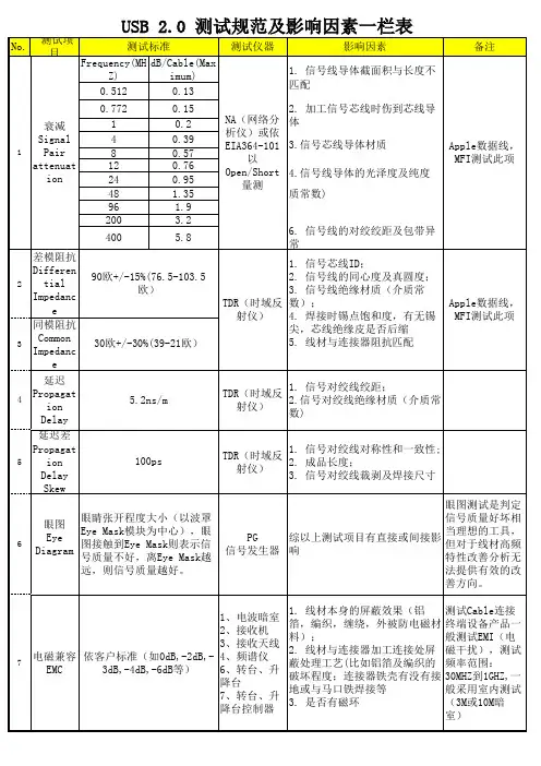
PRODUCT SPECIFICATION SPEC.NO. SPEC-USB 2.0Approved Date 02-26-2001 Name PRODUCT SPECIFICATION Amended Date 05-29-2003TYPEPLUG&RECEPTACLE Page 1 Sum To 8 PagesA&BTitle USB2.01.SCOPEThis specification covers performance, methods and quality requirements forUniversal Serial Bus (USB) plug and receptacle connectors. These connectorsare cable mounted plug and printed circuit board mounted receptacle connectors.2. REQUIREMENTS2.1 Design and ConstructionProduct shall be of the design , construction and physical dimensions specifiedThe in applicable product drawing.2.2 Materials and PlatingThey are specified on applicable product drawing.2.3 RatingsA.Voltage: 30 VAC (rms)B.Current: 1.5A per contact, not to exceed 30℃ temperature riseC.Operating temperature: -20℃ to +85℃D.Storage temperature: -25℃ to +85℃E.Nominal Temperature Rating: +20℃2.4 Test Requirements and Procedures SummaryD Amended 05-29-2003Check Director Tab C Amended 10-17-2001A Approved 02-26-2001陈永飞Description DateItem ChangePRODUCT SPECIFICATIONSPEC.NO. SPEC-USB 2.0Approved Date 02-26-2001 NamePRODUCT SPECIFICATIONAmended Date05-29-2003Title USB2.0 A&B TYPE PLUG&RECEPTACLE Page 2 Sum To 8 PagesNote:Shall meet visual requirements ,show no physical damage ,and shall meet requiremFigure 1 (conn.)Test DescriptionRequirement ProcedureLow level contact resistance for Lower and Middle stack 30mΩ maximum initial EIA 364-23 Subject mated contacts assembled in housing to 20 mV maximum open circuit at 100 mA maximum. See figure ALow level contact resistance for Upper stack 50mΩ maximum initial EIA 364-23 Subject mated contacts assembled in housing to 20 mV maximum open circuit at 100 mA maximum. See figure AInsulation resistance 1000 MΩ minimum EIA 364 – 21 Test voltage 500±50V/DC between adjacent contacts of mated and unmated connector assemblies.Dielectric withstanding Voltage No flashover&sparkover&excess leakage&breakdownEIA 364 – 20 Test voltage 500V/AC between adjacent contacts of mated and unmated connector assemblies.Vibration , random No discontinuities of 1u s orLonger duration.See Note.EIA 364 – 28A-83 Condition V Test Letter A. Subject mated connectors to 5.35 G's rms. 15 minutes in each of three mutually perpendicular planes ,See Figure B.Physical shock No discontinuities of 1u s or Longer duration.See Note. EIA 364 – 27 Condition H. Subject mated connectors to 30 Gs half-sine shock' pulses of 11 ms duration. three shocks in each direction applied along three mutually perpendicular planes ,18 total shocks ,See Figure C first test setup.Durability Contact Resistance:10 mΩ maximum change from initial value. EIA 364 – 09. 1500cycles insertion/extraction at a maximum rate of 200cycles per hour, then see note. Solderability USB contact solder tails shall pass95% coverage after one hour steam aging as specified in category 2.EIA364--52Cable pull-out Applied a load of 40 Newtons for one minute.EIA364-38 Test condition APRODUCT SPECIFICATION SPEC.NO. SPEC-USB 2.0Approved Date 02-26-2001 Name PRODUCT SPECIFICATION Amended Date 05-29-2003 Title USB2.0A&BTYPEPLUG&RECEPTACLE Page 3 Sum To 8 Pages Test Description Requirement ProcedureMating force 35 Newtons maximumEIA 364 – 13 Measure forcenecessary to mate connector Assembliesat maximum rate of 12.5 mm/min.Unmating force 10 Newtons minimumEIA 364 – 13 Measure forcenecessary to unmate connectorassemblies at maximum rate of 12.5mm/min.Thermal shock Contact Resistance:10 mΩ maximumchange from initial value.EIA 364 –32 Test Condition I.10Cycles –55℃ and +85℃,The USBconnectors under test must be mated.Critical Dimension 8 total measurement within tolerance.EIA 364-18Humidity Life Contact Resistance:10 mΩ maximumchange from initial value. The USB connectors under test must betested in accordance with EIA 364 – 31Condition A. method Ш. 168 Hours minimum (seven complete cycles).Temperature life Contact Resistance:10 mΩ maximumchange from initial value. See NoteEIA 364 – 17A-87 Condition 2 MethodA. Subject mated connectors totemperature Life at 85℃ for 250 hoursMixed Flowing Gas See NoteEIA 364-65-92 Class II, Exposures(1)U nmated for 1 day(2)M ated for 10 dayFlammability Require its thermoplastic resin vendorto supply a detailed C of C with eachresin shipment. The C of C shallclearly show the resin’s UL listingnumber, lot number, date code, etc.UL 94 v-0Note:Shall meet visual requirements ,show no physical damage ,and shall meet requirement.Figure 1 (conn.)PRODUCT SPECIFICATION SPEC.NO. SPEC-USB 2.0Approved Date 02-26-2001 Name PRODUCT SPECIFICATION Amended Date 05-29-2003 Title USB2.0A&BTYPEPLUG&RECEPTACLE Page 4 Sum To 8 Pages Test Description Requirement ProcedureContact capacitance 2 pF maximum unmated percontact.EIA 364 –30The object of this test is to detail a standardmethod to determine the capacitance betweenconductive elements of a USB connector.Contact current rating 1.5A at 250vAC minimumwhen measured at an ambienttemperature of 25℃, withpower applied to the contacts,the temperature change shallnot exceed +30 at any point inthe USB connector under test.EIA 364 – 70—method BThe object of this test procedure is to detail astandard method to assess the currentcarrying capacity of mated USB connectorcontacts.Differential impedance 90±15%Ω(76.5~~103.5Ω)Connect the Time Domain Reflectometer(TDR). TDR is setup the differential mode.Common mode impedance 30±30%Ω(21~~39Ω)Connect the Time Domain Reflectometer(TDR). TDR is setup the differential mode.Propagation Delay 26ns(maximum for full speed cable)Connect the Time Domain Reflectometer(TDR). TDR is setup the differential mode.Propagation delay skew 100ps/cable(maximum for full speed cable)Connect the Time Domain Reflectometer (TDR). TDR is setup the differential mode.Signal pair attenuation (Maximum) 0.064 MHz 0.08 dB/Cable1. Connect the Network Analyzer output port(port1) to the input connector on theattenuation test fixture(note).2. Connect the series “A” plug of the cable obe tested to the test fixture, leaving theother end open-circuited.3.Calibrate the network analyzer andfixture using the appropriate calibrationstandards over the desired frequencyrange.0.256 MHz 0.11 dB/Cable0.512 MHz 0.13 dB/Cable0.772 MHz 0.15 dB/Cable1.000 MHz 0.20 dB/Cable4.000 MHz 0.39 dB/Cable8.000 MHz 0.57 dB/Cable12.00 MHz 0.67 dB/Cable24.00 MHz 0.95 dB/Cable48.00 MHz 1.35 dB/Cable96.00 MHz 1.90 dB/Cable200.00 MHz 3.2 dB/Cable400.00 MHz 5.8 dB/CableNote: Shall meet visual requirements ,show no physical damage ,and shall meet requirementFigure 1 (conn.)PRODUCT SPECIFICATION SPEC.NO. SPEC-USB 2.0Approved Date 02-26-2001 Name PRODUCT SPECIFICATION Amended Date 05-29-2003 Title USB2.0A&BTYPEPLUG&RECEPTACLE Page 5 Sum To 8 Pages 2.5 Product qualification test sequence:Test ExaminationTest Group (a)1 2 3 4 5 6 8Test Sequence (b)Examination 1,10 1,6 1,6 1,9 1,3 1,6 1,3 Low level contactresistance3,7 2,5 2,5Capacitance 2Critical Dimension 2 Insulation resistance 3,7DWV 4,8Vibration 5Physical shock 6Durabillity 4 3 3Mating and unmatingforce2,8Thermal shock 5Humidity 6Temperature life 4Cable pull-out 9Mixed Flowing Gas 4Solderability 2Impedance 2Attenuation 3 Propagation delay 4Skew 5Number of samplesPlug 8pcs 8pcs 8pcs 8pcs 5pcs 5pcs 8pcs socket 8pcs 8pcs 8pcs 8pcs 5pcs 5pcs8pcs3. Sample Selection:Samples shall be prepared in accordance with applicable manufacturers instructions and shall be selected at random form current productions.PRODUCT SPECIFICATIONSPEC.NO. SPEC-USB 2.0Approved Date 02-26-2001 Name PRODUCTSPECIFICATION Amended Date05-29-2003TitleUSB2.0 A&B TYPE PLUG&RECEPTACLEPage 8 Sum To 8 Pages1.0 USB connector termination data:provide the standardized contact terminating assignments by number and electricalvalue for series “A” and series “B” connectors.1.1 USB connector termination assignment:Contact numberSignal nameTypical wiring Assignment1 Vbus Red2 D- White3 D+ Green4 GND Black shell Shield Drain Wire。
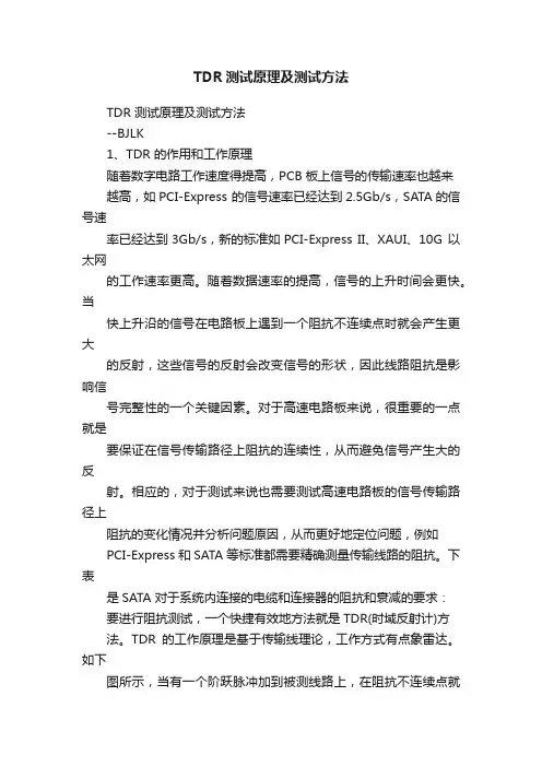
TDR测试原理及测试方法TDR 测试原理及测试方法--BJLK1、TDR 的作用和工作原理随着数字电路工作速度得提高,PCB 板上信号的传输速率也越来越高,如PCI-Express 的信号速率已经达到2.5Gb/s,SATA的信号速率已经达到3Gb/s,新的标准如PCI-Express II、XAUI、10G 以太网的工作速率更高。
随着数据速率的提高,信号的上升时间会更快。
当快上升沿的信号在电路板上遇到一个阻抗不连续点时就会产生更大的反射,这些信号的反射会改变信号的形状,因此线路阻抗是影响信号完整性的一个关键因素。
对于高速电路板来说,很重要的一点就是要保证在信号传输路径上阻抗的连续性,从而避免信号产生大的反射。
相应的,对于测试来说也需要测试高速电路板的信号传输路径上阻抗的变化情况并分析问题原因,从而更好地定位问题,例如PCI-Express 和SATA 等标准都需要精确测量传输线路的阻抗。
下表是SATA 对于系统内连接的电缆和连接器的阻抗和衰减的要求:要进行阻抗测试,一个快捷有效地方法就是TDR(时域反射计)方法。
TDR的工作原理是基于传输线理论,工作方式有点象雷达。
如下图所示,当有一个阶跃脉冲加到被测线路上,在阻抗不连续点就会产生反射,已知源阻抗Z0,则根据反射系数ρ就可以计算出被测点阻抗ZL的大小。
最简单的TDR 测量配置是在宽带示波器的模块中增加一个阶跃脉冲发生器。
阶跃脉冲发生器发出一个快上升沿的阶跃脉冲,同时接收模块采集反射信号的时域波形。
如果被测件的阻抗是连续的,则信号没有反射,如果有阻抗的变化,就会有信号反射回来。
根据反射回波的时间可以判断阻抗不连续点距接收端的距离,根据反射回来的幅度可以判断相应点的阻抗变化。
下图是TDR 的工作方式和对一个被测件的TDR 波形。
TDR 通常显示反射和阻抗变化情抗,TDT(时域传输)通常显示传输延迟。
器件或者通道的阻抗不连续会导致传输信号失真,因此TDR/TDT是增强信号完整性的重要工具。

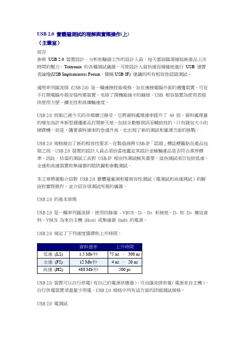
USB 2.0 實體層測試的理解與實際操作(上)〈主筆室〉前言參與USB 2.0 裝置設計、分析和驗證工作的設計人員,每天都面臨著縮短新產品上市時間的壓力。
Tektronix 的各種測試儀器,可使設計人員快速而精確地進行USB 建置者論壇(USB Implementers Forum,簡稱USB-IF) 建議的所有相容性認證測試。
通用串列匯流排(USB 2.0) 是一種連接技術規格,旨在連接電腦外面的週邊裝置,可在不打開電腦外殼安裝所需裝置,免除了開機箱插卡的麻煩。
USB 相容裝置為使用者提供使用方便、擴充性和高傳輸速度。
USB 2.0 技術已被今天的市場廣泛接受,它將資料處理速率提升了40 倍。
資料處理量的增加為許多新型週邊產品打開新天地,包括全動態視訊至輔助性的、只有錢包大小的硬碟機。
但是,隨著資料速率的急速升高,也出現了新的測試和量測方面的挑戰。
USB 2.0 規格推出了新的相容性要求。
在製造商將USB-IF「認證」標誌標籤貼在產品包裝之前,USB 2.0 裝置的設計人員必須恰當地鑑定其設計並檢驗產品是否符合業界標準。
因此,恰當的測試工具對USB-IF 相容性測試極其重要,這些測試項目包括低速、全速和高速裝置和集線器的眼狀圖和參數測試。
本文章將重點介紹對USB 2.0 實體層量測和電相容性測試(電測試和高速測試)的解說和實際操作,並介紹各項測試所需的儀器。
USB 2.0 的基本原理USB 2.0 是一種串列匯流排,使用四條線- VBUS、D-、D+ 和接地。
D- 和D+ 傳送資料。
VBUS 為來自主機(Host) 或集線器(hub) 的電源。
USB 2.0 規定了下列速度選擇和上升時間:USB 2.0 裝置可以自行供電(有自己的電源供應器),可由匯流排供電(電源來自主機)。
自行供電裝置須盡量少用電。
USB 2.0 規格中列有這方面的詳細測試規格。
USB 2.0 電測試USB 2.0 電測試包括訊號品質、峰值電流檢查以及壓降(Drop) 和浮動(Droop) 電壓測試。
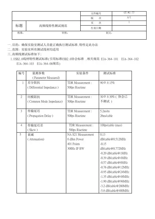
一.目的:确保实验室测试人员能正确执行测试标准.特性定此办法二.范围: 实验室所有测试线材均适用三.高频线测试标准如下:B2.0线材特性测试标准(引用标准USB2.0协会标准 .相关规范 EIA-364-101 EIA-364-102EIA-364-103 EIA-364-08规范)B3.0线材特性测试标准. (引用标准USB3.0协会标准 .相关规范 EIA-364-101 EIA-364-102EIA-364-103 EIA-364-08规范)3. DVI线材特性测试标准(引用标准DVI协会标准 .相关规范 EIA-364-101 EIA-364-102EIA-364-103 EIA-364-08规范)标题高频线特性测试规范生效日期核准:审核:制文:4. HDMI1.4线材特性测试标准(引用标准HDMI协会标准 .相关规范 EIA-364-101 EIA-364-102EIA-364-103 EIA-364-08规范)标题高频线特性测试规范生效日期核准:审核:制文:5.Displayport线材测试标准.(相关规范 EIA-364-101 EIA-364-102 EIA-364-103 EIA-364-08规范标题高频线特性测试规范生效日期核准:审核:制文:标题高频线特性测试规范生效日期核准:审核:制文:6. 网络线材CAT.5E特性测试标准:(引用EIA/TIA规范)6.1IMPZ 要求100+/-15 Ohm6.2Return LossParameter: Return Loss Unit: dB Start 1 4 8 10 16 20 25 31.25 62.5 100 1 10 20 End 1 4 8 10 16 20 25 31.25 62.5 100 10 20 100 SPEC Hi -20 -23 -24.5 -25 -25 -25 -24.3 -23.6 -21.5 -20.1 Fn:1 -25 Fn:1 6.3 AttenuationParameter: Attenuation@20℃Start 1 4 8 10 16 20 25 31.25 62.5 100End 1 4 8 10 16 20 25 31.25 62.5 100SPEC Hi -- -- -- -- -- -- -- -- -- --实验室文件修订履历表。
电线电缆标准
核准:制订:版次:1.0 修订日期:年月日单位:工程课总10页第1页受控号:
电线电缆标准
核准:制订:版次:1.0 修订日期:年月日单位:工程课总10页第2页受控号:
电线电缆标准
核准:制订:版次:1.0 修订日期:年月日单位:工程课总10页第3页受控号:
电线电缆标准
核准:制订:版次:1.0 修订日期:年月日单位:工程课总10页第4页受控号:
电线电缆标准
核准:制订:版次:1.0 修订日期:年月日单位:工程课总10页第5页受控号:
电线电缆标准
核准:制订:版次:1.0 修订日期:年月日单位:工程课总10页第6页受控号:
电线电缆标准
核准:制订:版次:1.0 修订日期:年月日单位:工程课总10页第7页受控号:
电线电缆标准
核准:制订:版次:1.0 修订日期:年月日单位:工程课总10页第8页受控号:
电线电缆标准
核准:制订:版次:1.0 修订日期:年月日单位:工程课总10页第9页受控号:
电线电缆标准
核准:制订:版次:1.0 修订日期:年月日单位:工程课总10页第10页受控号:。
USB 2.0Pre-Compliance Physical Layer TestingBrief Introduction to USB 2.0fFour wire system (D+, D-, VBUS, GND)f USB2.0 provides the following speed selectionsfSelf powered and Bus powered devices VBUS supplies power to devices that driver their primary power from the host or hub. f The USB-IF has instituted a certification and marking program–Persuade developers to fully test their USB devices. –New USB trademark logo that indicates a device is certified and conforms to all applicable USB 2.0 specifications.500 ps 480 Mbps High Speed4 –20 ns 12 Mbps Full Speed75 to 300 ns 1.5 Mbps Low SpeedRise Time Data RateUSB2.0一致性测试4Three categories of Compliance testing 0Physical layer (Electrical Test)0Protocol layer0Interoperability testing0USB 2.0 legacy tests0Signal Quality Test0Droop & Drop Test0Inrush Current Test0HS Specific Tests0Chirp Test0Monotonic Test0Receiver sensitivity Test0Impedance Test (TDR)USB2.0 信号质量测试信号质量测试包括:f眼图测试(Eye-Diagram testing)f信号速率(Signal Rate)f包结尾宽度(End of Packet Width)f交叉点电压范围(Cross-over voltage range (for LS and FS)) f JK抖动(JK jitter)f KJ抖动(KJ jitter)f连续抖动(Consecutive jitter)f单调性测试(Monotonic test (for HS))f上升与下降时间(Rise and Fall times)测试环境需求f500 MHz PC with Windows 2000 (English) or XP OS f High-Speed Host Controllerf USB-IF furnished Test Mode Softwaref Good quality USB cablesf Good quality USB Hub– 1.1 –Belkin F5U100 / F5U101– 2.0 –Belkin F5u221 / IOGer GUH-204 ‘Gold’ATEN UH-204 ‘Gold’f Mouse (any listed on USB-IF mouse)当DUT为Host时所测试的信号均为Host设备发出,其信号方向为下行(Down Stream)测试项1. Signal Quality–High speed test 480Mbit/S–Full speed test 12Mbit/S–Low speed test 1.5Mbit/S2. Droop( 压 落)3. Chirp (Shake Hands)Host High-Speed Signal Qualityconnector ,测Host High-Speed Signal Qualityf Win 2K (英文版) or XP PC 运行HSElecticalTestTool软件,选择HOST 然后按TEST.f进入下一个窗口在Port Control 内选择Test_packet, 在Port 内选择所要测试的Port 然后按EXECUTE.f Scope 执行TDSUSB2 软件,选择High Speed 然后将Signal quality 的六个项目全部点选.f Eye diagram, Signal rate, Rise time, Fall Time, EOP Width, Monotonic.f按下Configure 点选Configure 然后选择Tier 6, Down-stream, Near End. 点选Source 选择所要用的Input Channel.f点选RUN 的符号此时可看到TEST_PACKET 的波形f按下OK 既可完成测试Host High-Speed Signal QualityHost High-Speed Signal QualityRUNHost High-Speed Signal QualityÅWaveform Eye Diagram ÆHost High-Speed Signal Quality f Results: SummaryHost High-Speed Signal Quality f Results: DetailsReport GeneratorUtilities ÆReport GeneratorSelect 1. Tektronix Specific2. Plug-fest Specific3. CSV FormatFile nameHost Full-Speed Signal Quality1.1 HubSwitch set to INIT此connector直接,接到Hub1Host Full-Speed Signal Qualityf Win 2K ( ) or XP PC 不 执行HSElecticalTestTool软f测试 , Switch 切 INITf Scope 执行TDSUSB2 软 选择Full Speed 将Signal quality 项 选.f Eye diagram, Signal Rate, Rise time, Fall Time, EOP Width, Paired JK Jitter, Paired KJJitter, Consecutive Jitter, Cross Overf Configure 选Configure 选择Tier 6, Down-stream, Far End. 选Source 选择Input Channel.f 选RUN 时 Full-Speedf OK 测试Host Full-Speed Signal QualityHost Full-Speed Signal QualityÅWaveform Eye DiagramÆHost Low-Speed Signal Quality此connector直接,接到待测口Host Low-Speed Signal Qualityf Win 2K (英文版) or XP PC 不可执行HSElecticalTestTool软件f执行TDSUSB2 软件,选择Low Speed 然后将Signal quality 的九个项目全部点选.f Eye diagram, Signal Rate, Rise time, Fall Time, EOP Width, Paired JK Jitter,Paired KJ Jitter, Consecutive Jitter, Cross Overf按下Configure 点选Configure 然后选择Tier 6, Down-stream, Far End。
表单编号:002/版次:01 文件封面.目的:确保实验室测试人员能正确执行测试标准.特性定此办法二.范围: 实验室所有测试线材均适用三.高频线测试标准如下:B2.0线材特性测试标准(引用标准USB2.0协会标准 .相关规范 EIA-364-101 EIA-364-102EIA-364-103 EIA-364-08规范)B3.0线材特性测试标准. (引用标准USB3.0协会标准 .相关规范 EIA-364-101 EIA-364-102EIA-364-103 EIA-364-08规范)3. DVI线材特性测试标准(引用标准DVI协会标准 .相关规范 EIA-364-101 EIA-364-102EIA-364-103 EIA-364-08规范)4. HDMI1.4线材特性测试标准(引用标准HDMI协会标准 .相关规范 EIA-364-101 EIA-364-102EIA-364-103 EIA-364-08规范)标题高频线特性测试规范生效日期2013/1/12 核准:审核:制文:刘新崇5.Displayport线材测试标准.(相关规范 EIA-364-101 EIA-364-102 EIA-364-103 EIA-364-08规范标题高频线特性测试规范生效日期2013/1/12 核准:审核:制文:刘新崇标题高频线特性测试规范生效日期2013/1/12 核准:审核:制文:刘新崇标题高频线特性测试规范生效日期2013/1/12 核准:审核:制文:刘新崇6. 网络线材CAT.5E特性测试标准:(引用EIA/TIA规范)6.1IMPZ 要求100+/-15 Ohm6.2Return LossParameter: Return Loss Unit: dBStart 1 4 8 10 16 20 25 31.25 62.5 100 1 10 20 End 1 4 8 10 16 20 25 31.25 62.5 100 10 20 100 SPEC Hi -20 -23 -24.5 -25 -25 -25 -24.3 -23.6 -21.5 -20.1 Fn:1 -25 Fn:1 6.3 AttenuationParameter: Attenuation@20℃Start 1 4 8 10 16 20 25 31.25 62.5 100End 1 4 8 10 16 20 25 31.25 62.5 100SPEC Hi -- -- -- -- -- -- -- -- -- --SPEC Lo -2.4 -4.9 -6.9 -7.8 -9.9 -11.1 -12.5 -14.1 -20.4 -26.4实验室文件修订履历表。
USB2.0—HOST/SYSTEM测试方案参考资料:1.USB Spec2.02.Intel ICH4 USB Electrical Test Method(APAC Lab Workshop Q1/2002 ) 3.USBIF Full and Low Speed Compliance Test Procedure Rev。
1.0rc2 4.USBIF High-speed Electrical Test Toolkit Setup Instruction Rev.1.01 5.USBIF Host High-speed Electrical Test Procedure Rev.1.06.Tektronix USB2。
0 Compliance Test Fixture7.Tektronix USB Measurements Package说明:1.本测试方案适用于USB2。
0 HOST/SYSTEM级测试,包括主板;2.进行USB测试,所使用的连接电缆线规格:信号线:28 AWG;电源线:22或24AWG;本测试全部采用此种规格电缆线测试。
目录:一、信号质量测试1.高速信号质量测试2.全速信号质量测试3.低速信号质量测试二、Drop、Droop测试1.Drop测试2.Droop测试三、TDR测试一、信号质量测试1.高速信号质量测试1.1目的验证高速传输时,信号的质量;1.2标准通过高速传输眼图测试;1.3器材示波器:Tek 7404(加载软件:Tek USB2.0 Test Package);差分探头:Tek P7330×1个;夹具:Tek USB2。
0 Test Fixture(SQIDD板);测试软件:USBHSET.EXE (从USBIF网站下载、升级);USB电缆线:1米×1根;1.4步骤(1)连接如下,差分探头与夹具暂不连接:(2)设置夹具上开关S6在Init位置,通电;(3)被测设备(Host Under Test)预安装要求:•安装Win2000操作系统;•安装芯片组、ICH4驱动程序;•安装测试软件USBHSET.EXE;(4)设置示波器:•按示波器面板按键“default setup”,将示波器置于出厂设置;•进入菜单File--—Run Application,运行程序USB2。
Test Description Test Procedure Performance RequirementFlammability UL 94 V-0This procedure is to ensurethermoplastic resin compliance toUL flammability standards.The manufacturer will require itsthermoplastic resin vendor tosupply a detailed C of C with eachresin shipment. The C of C shallclearly show the resin’s UL listingnumber, lot number, date code,etc.Flammability UL 94 V-0This procedure is to ensurethermoplastic resin compliance toUL flammability standards.The manufacturer will require itsthermoplastic resin vendor tosupply a detailed C of C with eachresin shipment. The C of C shallclearly show the resin’s UL listingnumber, lot number, date code,etc.Cable Impedance(Only required for high-/full-speed)The object of this test is to insurethe signal conductors have theproper impedance.1. Connect the Time DomainReflectometer (TDR) outputsto the impedance/delay/skewtest fixture (Note 1). Useseparate 50 Ω cables for theplus (or true) and minus (orcomplement) outputs. Set theTDR head to differential TDRmode.2. Connect the Series "A" plug ofthe cable to be tested to thetext fixture, leaving the otherend open-circuited.3. Define a waveform composedof the difference between thetrue and complementwaveforms, to allowmeasurement of differentialimpedance.4. Measure the minimum andmaximum impedances foundbetween the connector and theopen circuited far end of thecable.Impedance must be in the rangespecified in Table 7-9 (Z O).110Test Description Test Procedure Performance RequirementSignal Pair Attenuation(Only required for high-/full-speed)The object of this test is to insurethat adequate signal strength ispresented to the receiver tomaintain a low error rate.1. Connect the Network Analyzeroutput port (port 1) to the inputconnector on the attenuationtest fixture (Note 2).2. Connect the Series “A” plug ofthe cable to be tested to thetest fixture, leaving the otherend open-circuited.3. Calibrate the network analyzerand fixture using theappropriate calibrationstandards over the desiredfrequency range.4. Follow the method listed inHewlett Packard ApplicationNote 380-2 to measure theopen-ended response of thecable.5. Short circuit the Series “B” end(or bare leads end, if a captivecable) and measure the short-circuit response.6. Using the software in H-P App.Note 380-2 or equivalent,calculate the cable attenuationaccounting for resonanceeffects in the cable as needed.Refer to Section 7.1.17 forfrequency range and allowableattenuation.111Test Description Test Procedure Performance RequirementPropagation Delay The purpose of the test is to verifythe end to end propagation of thecable.1. Connect one output of theTDR sampling head to the D+and D- inputs of theimpedance/delay/skew testfixture (Note 1). Use one 50 Ωcable for each signal and setthe TDR head to differentialTDR mode.2. Connect the cable to be testedto the test fixture. Ifdetachable, plug bothconnectors in to the matchingfixture connectors. If captive,plug the series “A” plug intothe matching fixture connectorand solder the stripped leadson the other end to the testfixture.3. Measure the propagation delayof the test fixture byconnecting a short piece ofwire across the fixture frominput to output and recordingthe delay.4. Remove the short piece of wireand remeasure thepropagation delay. Subtractfrom it the delay of the testfixture measured in theprevious step.High-/full-speed.See Section 7.1.1.1,Section 7.1.4, Section 7.1.16, andTable 7-9 (T FSCBL).Low-speed.See Section 7.1.1.2,Section 7.1.16, and Table 7-9(T LSCBL).112Test Description Test Procedure Performance RequirementPropagation Delay Skew This test insures that the signal onboth the D+ and D- lines arrive atthe receiver at the same time.1. Connect the TDR to the fixturewith test sample cable, as inthe previous section.2. Measure the difference indelay for the two conductors inthe test cable. Use the TDRcursors to find the open-circuited end of eachconductor (where theimpedance goes infinite) andsubtract the time differencebetween the two values.Propagation skew must meet therequirements as listed inSection 7.1.3.Capacitive LoadOnly required for low-speed The purpose of this test is to insurethe distributed inter-wirecapacitance is less than thelumped capacitance specified bythe low-speed transmit driver.1. Connect the one lead of theImpedance Analyzer to the D+pin on theimpedance/delay/skew fixture(Note 1) and the other lead tothe D- pin.2. Connect the series "A" plug tothe fixture, with the series “B”end leads open-circuited.3. Set the Impedance Analyzer toa frequency of 100 kHz, tomeasure the capacitance.See Section 7.1.1.2 and Table 7-7(C LINUA).Note1:Impedance, propagation delay, and skew test fixtureThis fixture will be used with the TDR for measuring the time domain performance of the cable under test. The fixture impedance should be matched to the equipment, typically 50 Ω. Coaxial connectors should be provided on the fixture for connection from the TDR.Note 2:Attenuation text fixtureThis fixture provides a means of connection from the network analyzer to the Series "A" plug. Since USBsignals are differential in nature and operate over balanced cable, a transformer or balun (North Hills NH13734 or equivalent) is ideally used. The transformer converts the unbalanced (also known as single-ended) signalfrom the signal generator which is typically a 50 Ω output to the balanced (also known as differential) and likely different impedance loaded presented by the cable. A second transformer or balun should be used on the other end of the cable under test to convert the signal back to unbalanced form of the correct impedance to match the network analyzer.113。