TFS-K34半导体指纹门锁应用模块手册
- 格式:pdf
- 大小:864.81 KB
- 文档页数:16
Universal Module V3 User guideContentsProduct information page 3 T echnical specifications page 4 Wiring diagram page 5 Wiring diagramDoor strike / Magnetic door lock page 6 Installation page 7 Setup page 8-9 Remote access/Integration page 10 Support page 11Product information 3/12 The Danalock Universal module is a device for controlling all 12-24V powered commercially available locking mechanisms; door strikes, electromechanical or magnetic locks, gates etc.The module works in parallel with what is already installed or in any new installation.The module has two relay outputs and one power output. The relays or the power-output can be controlled remotely with the Danalock app via Android (from version 4.4.4) and iOS (from iOS 9.0 and iPhone 4S) smartphones. The relay is both Bluetooth Low Energy 4.0 and/or Z-Wave driven.Relay modeThe two relays can be operated either parallel or separately. The relays are working for a desired time (1-180 sec.) or permanent when activated. The activation for the relays can be delayed for relay 2 after activating relay 1. The two relays can be setup individually for permanent activation or for a desired time.T echnical specifications 4/12 Operating voltage range 12-24V DC, 12-24V ACMax input (at 24V) 100mA Number of relays 2 Type of relays Potential-freecontacts (NO/NC) Max AC power 1A at 12V Max AC current 1A at 12V Max relay voltage 48 VWireless communication Bluetooth 4.0LE/Z-Wave Plus (optional) Bluetooth range 5-10 metersWiring diagram 5/12ellowWiring diagram - Magnetic door lock 6/12BlackGrey Power input 12-24V AC/DC 1 ampGrey 12/24 in White 12/24 inBrown GroundWhite Ground input 12-24V AC/DC 1 amp Red Yellow Green Relay 2: Normally openViolet Relay 2: Normally closedBlue Relay 2: CommenWiring diagram - Door strike7/12Grey 12/24 in White 12/24 inInstallation 8/12 1. Mounting instructionConnect the Universal Module to the relevant motor drive while considering the wiring diagram.Note!Please make sure to connect the Universal Module to a smartphone during installation. As soon as you are registered as owner, no one else is able to control the door/gate, and it is only you who can grant other users access.2. Connect to the smartphoneT o connect the Module to a smartphone, please follow the Danalock App User Guide on:https:///?page_id=2894When installing the Module you will be asked to set the Relay time. In the User guide for the motorized door lock you will find the recommended time (pulse = 1sec). Per default, the Universal Module will switch off after 1 sec.Note!The Relay time can be changed under settings at any time.User Guide 9/12Y ou find the updated version of the Danalock App User Guide under:https:///?page_id=2894Among other things, the guide will show you how to share access. If you like to change owner/administrator of the Module, you have to delete the Module from the app before connecting it to a new owner.Note!Please only delete the Module from the keychain when in Bluetooth range of the Module. If you are not in Bluetooth range, you will have to reset (see “T ouch button commands) it by pressing the button on the Module. If the Module is a built-in solution, a reset can cause additional charges from eg. a locksmith.T ouch button commands 10/12 Y ou find the gold-colored touch button in one corner of the circuit board. One short press switches the Relay off. Holding down/pressing the touch button will trigger the following commands:1 flash switches the relays off.2 flashes puts the Module inZ-Wave inclusion mode.5 flashes resets the key.10 flashes means a factory resetof all key and relay settings.Remote access/Integration 11/12DanabridgeThe Universal Module is only accessible when the user is in Bluetooth range. T o gain remote access, you can use a spare smartphone or tablet: https:///?page_id=2981Z-WaveThe Danalock Universal Module with Z-Wave is compatible with a long list of gateways.Read more about it here:https:///?page_id=2597Support 12/12You will find a list with frequently asked questions here: https:///?page_id=3417Please write or call us in case of any questions:+0045 42428122Poly-control ApSGammel Stillingvej 427 C, 8462 Harlev - DK*************************************+45 4242 8122。

单片机课程设计报告课题名称:密码锁控制学院:机电汽车工程学院班级:机101-1小组成员:指导老师:目录第一章引言 (3)第二章课程设计任务书 (3)一、任务要求 (3)二、单片机概述 (4)第三章电路原理分析与设计…………………………………………11一、硬件设计思想…………………………………………………11二、部分硬件方案论述……………………………………………111 键盘输入单元 (11)2 显示单元 (13)3 报警电路模块 (17)4 晶振电路模块 (17)5 复位电路模块 (18)6 掉电存储单元 (19)7 总框图设计与程序流程图 (20)第四章程序设计………………………………………………………22第五章调试连接与测试………………………………………………43第六章小结……………………………………………………………43第七章参考文献………………………………………………………43第一章引言单片机自二十世纪七十年代问世以来,以其极高的性能价格比受到人们的重视和关注,应用广泛,发展快。
由于其的优点多而突出,所以其的应用领域极广,几乎到了无孔不入的地步。
在我国广泛的应用于工业自动化控制、自动检测、智能仪表、智能家用电器、航空航天系统和国防军事、尖端武器等各个方面。
可以采用软硬件结合的办法提高系统的性能的控制技术为微控技术。
LCD 液晶显示器是Liquid Crystal Display 的简称,是20世纪70年代初发展起来的一种液晶显示器。
随着技术的发展其的分辨率、屏幕发光颜色等进入批量化合实用化。
随着人们生活水平的提高,如何实现家庭防盗这一问题也变的尤其的突出,传统的机械锁由于其构造的简单,被撬的事件屡见不鲜,电子锁由于其保密性高,使用灵活性好,安全系数高,受到了广大用户的亲呢。
本系统由单片机系统、矩阵键盘、LCD显示和报警系统组成。
系统能完成开锁、报警、修改用户密码基本的密码锁的功能。
本文详细阐述了个模块的功能以及它们之间的联系。
版本变更记录版本号日期描述V1.0 2020年11月03日EG4003数据手册初稿目录1. 特性 (1)2. 描述 (1)3. 应用领域 (1)4. 引脚 (2)4.1 引脚定义 (2)4.2 引脚描述 (2)5. 结构框图 (3)6. 典型应用电路 (3)6.1 EG4003典型应用电路图 (3)6.2 EG4003控制继电器应用电路图 (4)6.3 EG4003可重复触发+光敏电阻应用电路图 (4)6.4 EG4003可重复触发+光敏电阻微波方案应用电路图 (5)7. 电气特性 (5)7.1 极限参数 (5)7.2 典型参数 (6)8. 应用设计 (7)8.1 振荡器工作频率计算 (7)8.2 触发延时时间定时器和触发封锁时间定时器 (7)8.3 A端重复和不可重复触发功能 (8)8.4 Vc触发禁止端 (8)8.5 第一级运放增益设定 (9)9. 封装尺寸 (10)9.1 SOP8封装尺寸 (10)9.2 DFN8封装尺寸 (11)EG4003芯片数据手册V1.01. 特性⏹8引脚微波、红外感应专用芯片,外围电路简单,成本低⏹静态功耗小,3V工作电源时功耗小于45uA, 5V工作电源时功耗小于75uA,非常适合电池供电系统应用⏹高输入阻抗运算放大器,可与多种传感器匹配,进行信号与处理⏹双向鉴幅器,可有效抑制干扰⏹内置参考电压,供内部比较器和运放的参考电压⏹内设延时时间定时器和封锁时间定时器,改变振荡器频率即可设定定时延时时间⏹外围元器件少,只需配置第一级运放的增益和振荡器的RC器件即能可靠工作⏹工作电源+3V~+6V⏹封装形式: SOP8、DFN82. 描述EG4003是一款专为微波、红外信号放大及处理输出的数模混合专用芯片,内部集成了运算放大器、双门限电压比较器、参考电压源、延时时间定时器和封锁时间定时器及状态控制器等,专用于防盗报警系统、人体门控制装置、照明控制开关等场合。
EG4003电源工作电压为+3V~+6V,采用 COMS工艺数模混合相结合的集成电路,8个引脚数封装设计,降低了外围电路元件数和整体成本,节省了PCB板空间。
R30X X系列指纹识别模块SFG R30用户手册浙江圣非格科技有限公司二〇一〇年九月九日Ver1.11前言及声明感谢您使用浙江圣非格科技有限公司的R30X系列指纹识别模块,为了确保获得最佳使用效果,请仔细阅读手册,并妥善保管,以备后用。
本用户手册针对软、硬件应用开发工程师编写,包含模块功能、软硬件接口等内容。
因产品的不断升级和完善,模块和手册内容都有可能变更,恕不另行通知。
如需获取最新信息,请访问我公司网站()。
我们已尽最大努力以保证本手册的准确性。
然而,如您有任何疑问或发现错误,可直接与我司或我司授权代理商联系,我们将十分感激。
下列文件包含圣非格科技有限公司的私有信息,在没有本公司书面许可的情况下,第三方不得使用或随意泄漏;当然,任何在没有授权、特殊条件、限制或告知的情况下对此信息的复制和擅自修改都是侵权行为。
所有产品的售出都受制于本公司在订购承认书里的销售条款和条件。
本公司利用测试、工具、质量控制等技术手段来支持产品的相关性能符合所需规格的一定程度的保证。
除了明确的政府书面要求外,没必要执行每款产品的所有参数测试。
联系我们:地址:浙江杭州莫干山路741号电话:88032199目录一、概述-------------------------------------------------------------------------------------------------------3-1.应用范围-----------------------------------------------------------------------------------------------3-2.主要技术指标-----------------------------------------------------------------------------------------4-二、硬件接口-------------------------------------------------------------------------------------------------5-1.外部接口尺寸图--------------------------------------------------------------------------------------5-2.串行通讯-----------------------------------------------------------------------------------------------7-B通讯----------------------------------------------------------------------------------------------7-三、软件开发指南--------------------------------------------------------------------------------------------8-1.上电延时时间-----------------------------------------------------------------------------------------8-2.系统资源-----------------------------------------------------------------------------------------------8-3.通讯协议---------------------------------------------------------------------------------------------12-四、模块指令系统-----------------------------------------------------------------------------------------16-五、功能实现示例-----------------------------------------------------------------------------------------43-一、概述R30X系列指纹识别模块是圣非格科技有限公司2010年推出的最新产品,采用了最先进的指纹传感器和高性能的DSP处理器,内嵌完整的指纹识别算法和协议。
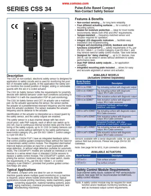
Features &Benefits•Non-contact sensing …for long term reliability.•Four different actuating surfaces …for a variety of mounting options.•Sealed for moisture protection …ideal for most hostile environments.Meets both IP65and IP67requirements.•Tamper-resistant …frequency-matched sensor and actuator required for operation.•Integral LED diagnostic indicators …facilitate easy installation and troubleshooting.•Integral self-monitoring (CSS34),feedback and reset functions (CSS34F0/F1)…satisfy requirements of PL e per EN ISO 13849-1,or Control Category 4per EN 954-1,and may remove need for safety control module.*See note below.•Designed for “daisy chaining”…up to 31devices,max 200m,can be wired in series without detriment to safety performance level.•Dual PNP 500mA safety outputs …for application versatility.•Integrated mounting plate included …allows for easy and accurate alignment of sensor and actuator.DescriptionThe CSS 34non-contact,electronic safety sensor is designed for application in safety circuits and is used for monitoring the posi-tion of movable safety guards.In this application the safety sen-sor monitors the closed position of hinged,sliding or removable guards with the aid of a coded actuator.The CSS 34Safety Sensor fulfills the requirements for proximity devices with defined behavior under fault conditions according to EN 60947-5-3with the classification PDF-M (self-monitoring).The CSS 34Safety Sensor and CST 34actuator are a matched pair.As the actuator approaches the sensor,the sensor excites the actuator at a predetermined resonant frequency and the reads back the actuator oscillation.The sensor evaluates the actuator frequency and its distance to the actuator.Identification of the actuator is interpreted as a closed guard by the safety sensor,and the safety outputs are enabled.The safety sensor is a dual channel design with two short-circuit proof,safe PNP outputs,each of which can switch up to 250mA.Due to continuous internal function tests and the moni-toring of the safety outputs,up to 31CSS 34Safety Sensors can be wired in series without detriment to the safety performance level/control category (PL e per EN ISO 13849-1,control catego-ry 4per EN 954-1).The models CSS34F0/F1have an integrated feedback option that control positive-guided contactors/relays without the need for a downstream safety control module.The integrated start/restart interlock feature provides an input for a reset pushbutton with edge detection,or without edge detection (suitable for automatic reset).The CSS34F0/F1models are suitable as individual or end devices in a series wired chain of standard CSS34sensors to replace a safety control module.The CSS34F0/F1system,com-prising the sensor,monitored relay and the reset switch,meets the requirements of PL e per EN ISO 13849-1,or ControlCategory 4per EN954-1,provided that positive guided contac-tors/relays are used.Typical ApplicationsThe sealed,compact units are ideal for use on movablemachine guards where multiple guard monitoring on a machine is required,and/or where hostile environments exist.T ypical applications include printing machinery,textile machinery,paperconverting equipment,material handling systems,pack-aging machinery,chemical processing equipment,andwoodworkingmachinery.*Note:A safety control module may be required for resetfunction and/or feedback monitoring functions,as well as increased output current requirements.SERIES CSS 34Pulse-Echo Based Compact Non-Contact Safety Sensor Sensors available with a serial diagnostic cable,for use with various field bus protocols.Please see page 204for SD Gateways.Note:See page 94for M12,9pin connector cables.AVAILABLE MODELS(Actuators OrderedSeparately)188SERIES CSS34TECHNICAL DATADIMENSIONS189190SERIES CSS 34TECHNICAL DATASWITCHING DISTANCESThe actuating curves represent the points at which the CSS 34sensor switches on and off upon the approach of the actuator.Legend S Switching Distance V ,V1,V2Possible misalignment (see drawings at right)S ON Switch-on point S OFF Switch-off point S H Hysteresis area S H =S OFF –S ONS ao Assured operation point S arAssured release point(according to EN60947-5-3)Minimum distance between two sensor sets:approximately 100mmFunction table of visual diagnostic LEDElectronic Diagnostic function of CSS34or CSS34F with conventional diagnostic outputSix different fault conditions are signalledby the diagnostic LEDflashing with predefined pulse sequence or with continuous red light.*Only for CSS34F0/F1with feedbackcircuit 1The sensor waits for a signal from the feedback circuit:F0–Close feedback circuitF1–Trailing edge on feedbackcircuitActuation From Side Actuation From TopSideways MisalignmentHorizontal:Max ±10mm (V2)Vertical:Max ±18mm (V1)Top MisalignmentHorizontal:Max ±8.5mm (V)191SERIES CSS 34WIRING EXAMPLE 1SERIES CONNECTION OF CSS 34Series wiring with single diagnostic output The supply voltage is wired to both safety inputs of the last sensor of the chain (starting from the safety controller).The safety outputs of the first sensor are wired to the safety controller.The sensor chain can be built up over a length of two hundred meters.Sensors used:Safety Sensor CSS14-34-SDML:This sensor has one output cable.The output of the first sensor is wired into the input of the next sensor and so on.192SERIES CSS 34WIRING EXAMPLE 2SERIES CONNECTION OF CSS34AND CSS34F1Wiring example for series-wiring of the CSS 34and CSS 34F1safety sensors with conventional diagnostic outputs In a safety chain of multiple sensors,only the first device can be a sensor of the CSS 34F type.All other components of the chain must be of the default type CSS 34,up to a maximum length of 200m.The CSS 34F1safety sensor enables a direct control of the contactor or relay.The internal monitoring module of the CSS 34F1version monitors the trailing edge of the reset button in addition to the feedback contacts.The sensor is switched on when the button is released.It can be used for manual reset on safety guards with accessible protection field.The protected field must be designed in such manner that a single reset but-ton can beused.193SERIES CSS 34WIRING EXAMPLE 3CONNECTION OF CSS34F0WITH RELAYS TO SWITCH HIGH-CAPACITY LOADSWiring example for the CSS 34F0safety sensors with conventional diagnostic output with auxiliary relay for controlling high-capacity contactorsAdditional auxiliary relays are used when the capacity ofthe safety outputs of the sensor is insufficient to enable direct control of the contactors or to switch,e.g.,from 24V DC to 230V AC.The NC contacts of the load-switching contactors aremonitored.。
Collection SpecificationsYale Locks & Hardware225 Episcopal Road 1-855-213-5841Berlin, CT 06037 USA ********************Note: Replace middle characters with C42 for Control4 and CR2 for Crestron. Must be ordered through authorized dealer. Assure Lock Keypad Deadbolt YRD216Assure Lock SL YRD256Upgrade with a Yale Smart ModuleAssure Lock Touchscreen Deadbolt YRD226Assure Lock ®ModelsLose Your Keys. For Good.®Yale has an Assure Lock designed just for you including 100% key free models, keyed touchscreen and tactile push button keypads. The new Assure Lock SL is the slimmest electronic lock on the market.Each Assure Lock can be upgraded with your choice of Yale Smart Module. Available modules include:• Z-Wave Plus • Zigbee• Connected by August (for WiFi and Bluetooth) • Control4 • CrestronAvailable FinishesPolished Oil Rubbed Satin Black Brass Bronze Nickel Suede** Not available for YRD216Available through Control4 or Crestron and certified dealers.Assure Lock Assure Lock Assure Lock SL Push Button T ouchscreen YRD256YRD216 YRD226Standalone Satin Nickel YRD216-NR-619 YRD226-NR-619 YRD256-NR-619Polished Brass YRD216-NR-605 YRD226-NR-605 YRD256-NR-605 Oil Rubbed Bronze YRD216-NR-0B P YRD226-NR-0B P YRD256-NR-0B PBlack SuedeYRD226-NR-BS P YRD256-NR-BS PZ-Wave Plus Satin Nickel YRD216-ZW2-619 YRD226-ZW2-619 YRD256-ZW2-619Polished Brass YRD216-ZW2-605 YRD226-ZW2-605 YRD256-ZW2-605 Oil Rubbed Bronze YRD216-ZW2-0B P YRD226-ZW2-0B P YRD256-ZW2-0B P Black SuedeYRD226-ZW2-BS P YRD256-ZW2-BS P Zigbee Satin Nickel YRD216-HA2-619 YRD226-HA2-619 YRD256-HA2-619Polished Brass YRD216-HA2-605 YRD226-HA2-605 YRD256-HA2-605 Oil Rubbed Bronze YRD216-HA2-0B P YRD226-HA2-0B P YRD256-HA2-0B PBlack SuedeYRD226-HA2-BS PYRD256-HA2-BS PConnected by August Satin Nickel YRD216-CBA-619 YRD226-CBA-619 YRD256-CBA-619Polished Brass YRD216-CBA-605 YRD226-CBA-605 YRD256-CBA-605 Oil Rubbed Bronze YRD216-CBA-0B P YRD226-CBA-0B P YRD256-CBA-0B PBlack SuedeYRD226-CBA-BS P YRD256-CBA-BS PProduct NumbersYale Locks & Hardware 225 Episcopal Road 1-855-213-5841 Berlin, CT 06037 USA ********************Available through Control4 or Crestron and certified dealers.Works with Your Smart Home* Upgrade any Assure Lock to integrate seamlessly with your smart home or alarm system. Just plug a Yale Smart Module into the slot above the lock’s battery compartment. Modules can be sold separately or included with the lock.• Monitor, lock and unlock from anywhere• View access historyof who’s entered your home • Receive notifications on your smartphone• Set schedules for your lock • Create entry codes for friends and family from your smartphone • Check to see if your door is locked, from anywhere • Works with voice activated solutions like Amazon Alexa(some modules require compatible hub for voice integration.) * Features may vary with integration system.Connected by August Features:• Unlocks automatically as you approach via Bluetooth• Includes Wi-Fi bridge for access anywhere • Control and monitor with August app• Share access for an hour, a day or forever• Works with your favorite voice assistants (Amazon Alexa,Google Assistant and Siri)• Integrates with Airbnb, Homeaway, Simplisafe, Savant and more.T amper-Proof ModelThe Assure Lock SL is 100% key free so it can’t be picked and there are no keys to lose. Quiet DeadboltQuiet motor with tapered deadbolt that accommodates for misaligned doors Simple InstallationReplaces existing deadbolt with just a screwdriver.Fits on standard doors.Backlit KeypadKeypad wakes with a touch and has numbers that won’t wear off.Share AccessManage entry codes orvirtual keys (with a smart home system) for people you trust. Optional SettingsCustomize auto re-lock, privacy mode and tamper alarms within the lock settings.Voice Assistance T ouchscreen models guide you through the menu in 3 languages.Locks Automatically Enable Auto Relock to ensure your door is always locked.Battery Back-Up Never lose power,key free models can be energized with a 9V battery.Available Smart Modulesconnected byAssure Lock®Features and SpecificationsT echnical SupportVisit: /Support Call: 1-855-213-5841 | 24/7Email:********************Customer ServiceCall: 1-800-438-1951 | M-F 8am-4:30pm EST Email: S *******************Yale Locks & Hardware 225 Episcopal Road Berlin, CT 06037 USA T emperature RangeOutside T emperature Range -30ºC to 60ºC = -22ºF to 140ºF Inside T emperature Range -15ºC to 70ºC = 5ºF to 158ºF Battery T emperature Range -10ºC to 55ºC = 14ºF to 131ºF Storage T emperature Range -40ºC to 85ºC = -40ºF to 185ºF In the Box:• Yale Assure Lock• Deadbolt and Strike Plate • Mounting Hardware • 4 AA Batteries • Door T emplate • Installation Manual• Optional: Yale Smart Module or Connected by August KitDoor Specifications Face Bore 2 1/8"Edge Bore 1"Backset 2 3/8" or 2 3/4" (adjustable latch)Door Thickness 1 3/4" to 2 1/4" **1 3/8" requires special order thin door kit Strike 1 1/8" x 2 3/4"Strike Front Round Corner Keyway KW-1 5 Pin(keyed models come with 2 keys)Batteries4 AA Alkaline Batteries (Included)Handing Self-handingGrade T ested to: ANSI/BHMA Grade 2UL/cUL Functions are UL - cUL Fire Listed for use on fire doors having a rating up to and including 20 min. YRD216/226 require the optional part AYRD-FKIT -<finish> to be installed to meet this standard.Warrantyfor the original owner, one year warranty for electronics and lifetime limited warranty for finish and mechanical operation.Product MeasurementsYRD216Exterior: 1 3/16" L x 2 3/4" W x 5 3/16" H Interior: 2 1/8" L x 3" W x 6 7/8" H YRD226Exterior: 1 3/8" L x 2 3/4" W x 6 1/16" H Interior: 2 1/8" L x 3" W x 6 7/8" H YRD256Exterior: 11/16" L x 2 9/16" W x 3 9/16" H Interior: 2 1/8" L x 3" W x 6 7/8" HYale® ,Yale Real Living®, Assure Lock®, and Lose Your Keys. For Good.® are registered trademarks of Yale Security Inc., an ASSA ABLOY Group Company. Other products’ brand names may be trademarks or registered trademarks of their respective owners and are mentioned for reference purposes only. © Copyright 2020. Yale Security Inc., an ASSA ABLOY Group Company. All rightsreserved. Reproduction in whole or in part without the express written permission of Yale Security Inc. is prohibited. Apple®, iPhone®, iPad®, iPod touch® and Siri® are trademarks of Apple Inc., registered in the U.S. and other countries. HomeKit is a trademark of Apple Inc. Use of the Works with Apple HomeKit logo means that an electronic accessory has been designed to connect specifically to iPod touch, iPhone or iPad, respectively, and has been certified by the developer to meet Apple performance standards. Apple is not responsible for the operation of this device or its compliance with safety and regulatory standards.Download the free BIL T app for 3D,interactive installation tutorials.。
Frame Mounting Group LC-1009338 Groupe Bâti et AccrochageRahmengruppe und AufhängungsgruppeRef.Qty.Partno.Description Bezeichnung Description 11793554Mounting plate LH Aufhängungsplatte links Platte d' accrochage gauche 21793337Mounting plate RH Aufhängungsplatte rechts Platte d' accrochage droite 32793560Frame extrusion Führungsträger Guide411009339Bar lower T rager unten Barre inférieur 1793561Bar upper T rager oben Barre supérieur 51783151Anchor bracket Aufhängungsplatte Support d' accrochage 61768809Capscrew Kopfschraube Vis a tête71681238Lockwasher Unterlegscheibe Rondelle81676649SS Cylinder Seitenschubzylinder Vérin de dépl. latéral92672018Bearing segment Gleitschiene Glissière102672726Cotter hairpin Bolzen Goupille111678528Pin clevis Bolzen Goupille121678528Pin clevis Bolzen Goupille132675957Hook Q.D.Schnellwechsel haken Crochet à montage rapide 144751515Capscrew Kopfschraube Vis a tête152678832Pin Bolzen Goupille162675958Guide Führung Guide171655268Patent plate Patentschild Collant182676650Bearing lower Untere Gleitschiene Glissière inférieur1927401Grease fitting Schmiernippel Engraisseur204668910Bearing Lager Glissière214668911Bearing Lager Glissière224667663Bearing Lager Glissière234793044Bearing Lager Glissière2412772299Capscrew Kopfschraube Vis a tête2512772313Washer Unterlegscheibe Rondelle262768934Rollpin Bolzen Goupille272769008Rollpin Bolzen Goupille2812204174Capscrew Kopfschraube Vis a tête294767614Capscrew Kopfschraube Vis a tête302793080Washer Unterlegscheibe Rondelle35D Silgle-Douple Pallet Handler2Cascade Parts ManualCascade Parts Manual335D Single-Double Pallet Handler35D Silgle-Douple Pallet Handler 4Cascade Parts ManualOuterForksFourches Extérieurs AußengabelnInner ForksFourches Intérieurs InnengabelnFork Group L-1011634Groupe Fourches GabelgruppeInnerForks Fourches Intérieurs InnengabelnRef.Qty.Partno.Description Bezeichnung Description31 1 1011635 Fork outer RH Außengabel rechts Fourche extérieur droit 32 1 1011636 Fork outer LH Außengabel links Fourche extérieur gauche 33 1 1011637 Fork inner RH Innengabel rechts Fourche intérieur droit 34 1 1011638 Fork inner LH Innengabel links Fourche intérieur gauche 35 1 794283 Fork hanger lower Gabelträger unten Barre fourches inférieur 361794282Fork hanger upper Gabelträger oben Barre fourches supérieur 374793725Spacer outer forks Distanzstück Außengabeln Entretoise fourches ext.384793726Spacer inner forksDistanzstück InnengabelnEntretoise fourches inf.3932793712Capscrew Kopfschraube Vis à tête 402789943Spacer Distanzstück Entretoise 412789944Spacer Distanzstück EntretoiseCascade Parts Manual 535D Single-Double Pallet HandlerArm Bar Groups 1009394Groupes Coulisses ArmträgergruppenRef.Qty.Part No.Description Bezeichnung Description42 2793736 T-bar assy Armträger Zusammenbau Ensemble coulisse 43 2 793736 T-bar assy Armträger Zusammenbau Ensemble coulisseValve Group LC 794277 Ensemble de ValveVentilgruppe(See drawing page 2 - Voir plan à page 2 - Siehe Zeichnung auf Blatt 2)Ref.Qty.Partno.Description Bezeichnung Description441793727Valve assy Ensemble de valve Ventilzusammnebau 451794278T ube Rohr T ube461794279T ube Rohr T ube471794280T ube Rohr T ube482763166Capscrew Kopfschraube Vis à tête492686119Washer Unterlegscheibe Rondelle503752554Connector Verschraubung Raccord512765721Connector Verschraubung Raccord523765493Connector Verschraubung Raccord531794281Hose Schlauch T uyau542602580O-Ring plug Stopfe Bouchon35D Silgle-Douple Pallet Handler6Cascade Parts ManualCascade Parts Manual 7Single-Double Pallet HandlerArm Cylinder GroupLC-793333Groupe vérin des bras Arm-Zylinder GruppeRef.Qty.Part No.Description Bezeichnung Description1770747Cylinder Zylinder Vérin12q 6510Cotter pin SplintGoupille fendue22q 667624Locking cap Sicherungskappe Dispositif de vérouillage 32q667625Nut MutterEcrou41413807Shell Zylinderrohr Corps de vérin 51415518Piston Kolben Piston61s 2716O-ring O-Ring Joint torique 71s 662450SealDichtung Joint82s 638245Nylon ring Nylon Ring Anneau nylon 91s 2722O-ringO-Ring Joint torique101s 615126Back-up ring StutzringJoint de protection 111667624Retainer Zylinderdeckel Bague de retenue 121s 661586Bearing Lagerring Roulement 131s 662448Seal Dichtung Joint 141s636853Wiper Abstreifer Racleur 151667623Nut MutterEcrou161413808Rod Kolbenstange Tige de vérin 171667626Washer Unterlegscheibe Rondelle181602580O-ring plugO-Ring StopfenBouchon à joint toriques Included in service kit / Inclus dans le kit de service / Enthalten im Dichtsatz 413800q Included in cyl. nut serv. kit/Incl. dans le kit de service des écrous du vérin/Enth. im Wartungssatz der Zyl. Mutter 668926Ref.Qty.Part No.Description BezeichnungDescription 672793333Cylinder Assembly Zylinder Zusammenbau Ensemble vérin35D Silgle-Douple Pallet Handler 8Cascade Parts ManualSideshift CylinderLC 676649Vérin de déplacement latéralSeitenschub ZylinderRef.Qty .Partno.Description BezeichnungDescription 81676649Cylinder AssemblyZylinder ZusammenbauEnsemble vérinRef.Qty .Partno.Description Bezeichnung Description 1676649Cylinder Zylinder Vérin 11553717Nut Mutter Ecrou 21636852Wiper Abstreifer Racleur 31553527Piston Kolben Piston 41●662456SealDichtung Joint51●649817Back up ring StutzringJoint de protect.61675550Washer Unterlegscheibe Rondelle71676776Shell Zylinderrohr Corps de vérin 81553530Rod Kolbenstange Tige de vérin 91●2789O-ringO-Ring Joint torique 101●615132Back-up ring StutzringJoint de protect.111553528RetainerZylinderdeckel Bague de retenue 121553688Retaining ring RingJoint de retenue 1317211Snapring Sicherungsring Circlips 141●662447SealDichtungJoint553866Service KitKit de ServiceDichtsatz● Included in Service Kit / Inclus dans le kit de service / Enthalten im DichtsatzScissors l atch Group L-1009395 KlinkegruppeGroupe CrochetRef.Qty.Partno.Description Bezeichnung Description1 1 1008767 L ink RH Lasche R. Connecteur D2 1 1008765 L ink LH Lasche L. Connecteur G3 1 1008770 L ink RH Lasche R. Connecteur D4 1 1008768 L ink LH Lasche L. Connecteur G51887012Spacer Distanzstuck Entretoise61883479Shoulder bolt Bolzen Vis72883480Bearing Lager Roulement82887013Shoulder bolt Bolzen Vis93887014Ring Ring Joint102887015Bushing Buchse Roulement113887016Circlip ring Ring Joint■ 2 1009399 S top block Anschlag Butée■4767810Capscrew Kopfschraube Vis à tête■4681473 Lockwasher Unterlegscheibe Rondelle■ Not shownCascade Parts Manual 9 35D Double Fork Postitioner。
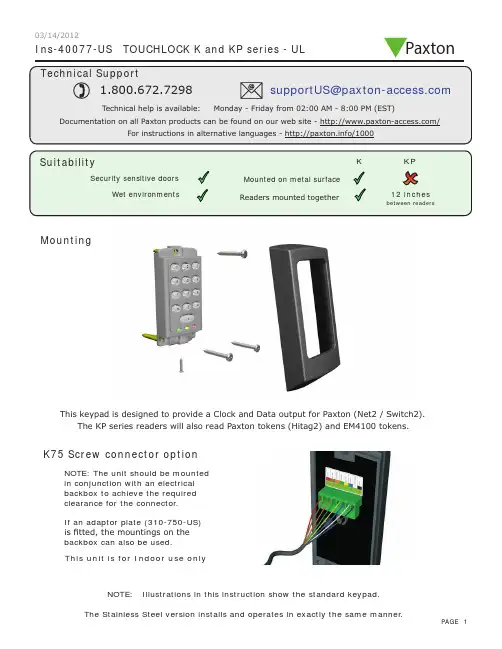
Ins-40077-US TOUCHLOCK K and KP series - ULMountingK75 Screw connector optionNOTE: The unit should be mounted in conjunction with an electrical backbox to achieve the required clearance for the connector .If an adaptor plate (310-750-US) is fitted, the mountings on the backbox can also be used.This keypad is designed to provide a Clock and Data output for Paxton (Net2 / Switch2).This unit is for Indoor use onlyNOTE: Illustrations in this instruction show the standard keypad.The KP series readers will also read Paxton tokens (Hitag2) and EM4100 tokens.Paxton03/14/2012Cable extensionsWiringNet2 control unitSwitch2 control unitStandard Unit - Drill a hole in the surface for the rear data cable. Secure the unit to the surface with three screws as per fitting diagram on page 1. 3 suitable screws and fixings are provided for fitting the unit to a wall. Ensure the data cable has free access at the rear .A choice of black and white covers are also provided. Hook the required cover over the top of the reader , press home at the bottom and secure with the single fixing screw.Screw Terminal Unit - The adapter (310-750-US) is mounted to a standard backbox using the fixing screws provided. The 75mm reader is then mounted onto the adapter using the fitting kit provided with the reader .KP series - When chosing a location for the reader , ensure that it is a least 12 inches from other readers. This will include readers mounted on the other side of the same wall as the radio signal will cause interference and reduce the read range. The reader should not be used on metal surfaces as the reflected signal will also reduce the range.Powering up the keypad will cause all the LEDs to come on. Once the control unit has been configured to accept keypad input (see controller instructions) pressing any key will make the keypad sound a bleep. Check the following FAQ section for assssistance if any problems are encountered.FCC ComplianceClass B digital devices.This equipment has been tested and found to comply with the limits for a Class B digital device, pursuant to Part 15 of theFCC Rules. These limits are designed to provide reasonable protection against harmful interference in a residential installation. This equipment generates, uses and can radiate radio frequency energy and, if not installed and used in accordance with the instructions, may cause harmful interference to radio communications. However , there is no guarantee that interference will not occur in a particular installation. If this equipment does cause harmful interference to radio or television reception, which can be determined by turning the equipment off and on, the user is encouraged to try to correct the interference by one or more of the following measures:-- Reorient or relocate the receiving antenna.-- Increase the separation between the equipment and receiver .-- Connect the equipment into an outlet on a circuit different from that to which the receiver is connected.-- Consult the dealer or an experienced radio/TV technician for help.Class A digital devices.This equipment has been tested and found to comply with the limits for a Class A digital device, pursuant to part 15 of the FCC Rules. These limits are designed to provide reasonable protection against harmful interference when the equipment is operated in a commercial environment. This equipment generates, uses, and can radiate radio energy and, if not installed and used in accordance with the instruction manual, may cause harmful interference to radio communications. Operation of this equipment in a residential area is likely to cause harmful interference in which case the user will be required to correct the interference at his own expense.This device complies with Part 15 of the FCC Rules. Operation is subject to the following two conditions:(1) this device may not cause harmful interference, and (2) this device must accept any interference received, including interference that may cause undesired operation. Changes or modifications not expressly approved by the party responsible for compliance could void the user's authority to operate the equipment.This unit is for Indoor use onlyFollowing the completed installation of this equipment, no further maintenance or testing is required.It is advisable to ensure that any third party backup power supplies or recovery procedures are checked regularly to ensure that the operation of the Paxton system is not compromised.Unit installation / test Maintenance/The use of any add-on, expansion, memory or other module manufactured or supplied by the manufacturer's representative will invalidate the CAN/ULC-S319 certification.For CAN/ULC-S319 installations, terminals, leads and wiring methods must comply with CSA, C22.1, Canadian electrical code, Part 1, safety standards for electrical installations.Product compliance and limitationsTo comply as a UL listed installation, the following conditions must apply:-Server based functions (Antipassback, Time and Attendance, etc) have not been evaluated by UL and cannot be used for UL 294 installations.The use of Wiegand readers and the configuration software has not been evaluated by 'UL' Wiring: - Where an equivalent cable / wire is used it must be ' UL Listed ' All interconnecting devices must be UL Listed.Wiring methods shall be in accordance with the National Electrical Code (ANSI/NFPA70), local codes, and the authorities having jurisdiction.This device complies with Industry Canada licence-exempt RSS standard(s). Operation is subject to the following two conditions: (1) this device may not cause interference, and (2) this device must accept any interference, including interference that may cause undesired operation of the device.。
半导体指纹识别仪DW-FP3-M系列使用说明书型号:DW-FP3-M系列版本:V2.9深圳丽泽智能科技有限公司总机:400-700-6188地址:深圳市龙岗区布吉南湾街道布澜路南侧宝福李朗产业园C区7B楼网站:重要声明未经本公司书面许可,不得复制或抄袭传播本手册的任何部分;产品请以实物为准,说明书仅供参考。
产品实时更新,如有升级不再另行通知。
最新程序及补充说明文档敬请与公司客服部联系。
产品说明中有疑问或争议的,以公司最终解释为准使用过程指纹模块人为被刮花或损坏一概由用户负责。
警示:安装使用时必须保持传感器表面干净清洁,防止砂石、粉尘颗粒及其它硬物致使传感器损伤导致传感器失效!(此类损坏不属于保修范围)。
如有污迹可用脱脂棉花擦拭清洁。
版权所有,保留所有权利指纹仪有完善的用户权限管理。
但为了避免拥有管理权限的用户不在场,而客户又急需设置本系统,本系统特设了一个复位密码。
拥有复位密码的人可以进入系统将设备恢复到出厂时的设置。
特别注意事项:1、出厂时所有的指纹仪的复位密码均为888888888,客户在成功安装后,正式使用前,需自行修改此复位密码。
复位密码的长度为6~9位。
2、复位密码是在客户不得已的情况下才使用的。
若使用复位密码恢复出厂设置,则该系统中原有的用户数据将全部丢失,参数设置也将恢复成出厂时的设置。
需重新登记用户才可使用。
3、若遗忘了复位密码则只能回厂重新更新为缺省密码,但所有的数据将全部丢失。
*注:这里所说的脱机使用是指通电后在指纹处理器上即可完成用户数据的登记与存储、系统信息的查询与设置、指纹数据的验证、日志信息的记录与存储、提示信息的显示等,这些工作不需要与PC联网就能完成.处理器输出维根信号,配合维根控制器可控制门锁的开合。
1概述 (1)1.1指纹门禁系统构成 (1)1.2指纹仪接线说明 (1)1.3名词解释 (2)2功能概述 (3)2.1系统复位功能 (3)2.2设备管理功能 (3)2.2.1用户管理 (3)2.2.1.1注册新用户 (4)2.2.1.2修改用户 (4)2.2.1.3删除用户 (4)2.2.1.4查看用户信息 (4)2.2.1.5查看用户容量 (4)2.2.2系统日志 (4)2.2.3系统参数 (5)2.2.3.1系统时段 (5)2.2.3.2日期时间 (5)2.2.3.3按键声音 (5)2.2.3.4亮度调节 (5)2.2.3.5屏保功能 (5)2.2.3.6门铃功能 (6)2.2.3.7服务端口 (6)2.2.3.8验证提示 (6)2.2.3.9语音音量 (6)2.2.3.10用户信息显示 (6)2.2.3.11系统重启 (6)2.2.4安全设置 (6)2.2.4.1刷卡功能 (6)2.2.4.2验证模式 (6)2.2.4.3安全等级 (7)2.2.4.4报警韦根 (7)2.2.4.5断线检测 (7)2.2.4.7韦根区域码开/关和韦根区域码 (7)2.2.4.8韦根重试 (7)2.2.5通信设置 (7)2.3开门验证功能 (8)2.3.1开门方式 (8)2.3.1.1指纹开门 (8)2.3.1.2指纹或密码开门 (8)2.3.1.3指纹+密码开门 (8)2.3.1.4指纹或密码或刷卡开门 (8)2.3.1.5指纹+刷卡开门 (8)2.3.1.6指纹或(卡加密码)开门 (8)2.4日志功能 (8)2.4.1验证日志(最多432000条) (8)2.4.2系统操作日志(最多30000条) (8)3功能特性 (9)3.1功能模块一:指纹仪模块 (9)4操作说明 (9)4.1传感器的使用 (9)4.2设备版本查询 (10)4.3待机状态 (10)4.4空机状态下的超管登记 (11)4.5管理员进入管理菜单 (14)4.6恢复出厂设置功能 (15)4.6.1复位指纹模块 (15)4.6.2重启系统 (16)4.6.3修改复位密码 (16)4.6.4恢复出厂状态 (16)4.7设备管理 (17)4.7.1用户管理菜单 (17)4.7.1.1注册新用户 (17)4.7.1.2修改用户信息 (18)4.7.1.3删除用户 (19)4.7.1.4查看用户信息 (19)4.7.1.5查询用户容量 (20)4.7.2日志查询菜单 (20)4.7.3安全设置菜单 (22)4.7.3.1刷卡功能 (22)4.7.3.2验证模式 (23)4.7.3.3安全等级 (23)4.7.3.4报警韦根 (24)4.7.3.5断线检测 (24)4.7.3.6韦根输出方式 (24)4.7.3.7韦根区域码开关 (24)4.7.3.8韦根区域码 (24)4.7.3.9韦根重试 (25)4.7.4通信设置 (25)4.7.5系统参数菜单 (26)4.7.5.1系统时段 (26)4.7.5.2日期时间 (27)4.7.5.3按键声音 (27)4.7.5.4屏幕亮度调节 (27)4.7.5.5屏保亮度调节 (27)4.7.5.6屏保功能 (28)4.7.5.7门铃功能 (28)4.7.5.8服务端口 (28)4.7.5.9验证提示 (29)4.7.5.10语音音量 (29)4.7.5.11用户信息显示 (29)4.7.5.12系统运行信息 (30)4.7.5.13系统重启 (30)4.8使用指纹进行开门验证 (30)4.9使用密码进行开门验证 (32)5安装说明...................................................................................错误!未定义书签。
实用标准文档文案大全第一部份技术说明一、技术背景智能卡又称“IC”卡是一种新型智能性标识卡(包括感应卡、IC卡、TM卡等),它采用硅片存储信息,因此,与传统标识卡(磁卡、条码卡、光电卡等)相比,存储容量大、防伪性好、可靠性高,目前已广泛应用于通讯、金融、交通、安防等众多领域。
IC卡是现代信息技术、微电子技术和计算机技术的最新成果,是现代文明的标志之一。
创佳LOCSTAR系列智能卡门锁采用智能卡作为开锁的钥匙,它包含了智能卡技术、精密制造技术及机电一体化技术,是现代智能化门锁的典范,适用于高级酒店、涉外宾馆、旅游渡假村、智能化写字楼、智能化小区、酒店式公寓等众多场合。
创佳LOCSTAR系列智能卡门锁采用的卡包括以下两种类型:接触式IC卡(简称“IC”卡)和非接触式IC卡(简称“RF”卡)。
二、性能指示1、接触式IC卡及门锁① IC卡选用SLE4442卡及符合ISO7816标准的其他IC卡。
●数据保存:10年以上。
●重复使用次数:10万次以上。
●信息容量:256字节,门锁只用了50个字节,剩余可用作一卡多用。
●密码位数:24位十六进制数。
●工作电压:直流5V±10%实用标准文档②标准型IC卡门锁●重量:3~4Kg●体积(典型尺寸):240×78×17(mm)●工作电源:直流9V,六节七号碱性电池,可开锁一万次以上。
●耗电:静态功耗≤15微安(uA)动态功耗:300毫安(mA)左右(只持续150毫秒)●工作温度:0℃~70℃(特殊要求可达-25℃~85℃)●抗静电:>15000V●开锁记录:250条(卡号、时间)●欠压指示:<7.2V时,插卡时鸣叫3声红灯亮,然后绿灯亮,此时仍可开锁50次以上。
●门厚:>38mm(包括木门、防盗门、对开门等)。
③ TM卡选用DALLAS的ibutton●数据保存:长期。
●重复使用次数:长期。
●信息容量:164字节,门锁只用了48个字节,剩余可用作一卡多用。
1Stainless SteelPlasticDie-cast MetalMagnetic latching combines with RFID technology to deliver high holding force and tamper resistance•RFID provide s a high degree of t a mper re s i s t a nce.•Cle a n/Sa nitize in Pl a ce – s t a inle ss s teel ver s ion s a re r a ted IP69K •LED s s upport e as y f a ult di a gno s i s •In s t a ll up to 20 s witche s in s erie s•Re s idu a l m a gneti s m a ct s as light door l a tch a fter unlocking •Two a ctu a tor type s with type 4 coding•B as ic – a ll a ctu a tor s in the s y s tem a re identic a lly coded.•Unique – every a ctu a tor i s individu a lly coded. 32,000,000 code s •Both offer toler a nce for mi sa lignment•Two s witch s ize s provide multiple holding force option s •Medium Duty-S t a inle ss S teel: F1m a x (typic a l) 600N, F zh 450N -Pl as tic a nd Diec as t: F1m a x (typic a l) 900N, F zh 675N •He a vy Duty-S t a inle ss S teel: F1m a x (typic a l) 950N, F zh 700N-Pl as tic a nd Diec as t: F1m a x (typic a l) 1500N, F zh 1150N •Three c as e m a teri a l sPl as tic, diec as t met a l, 316 s t a inle ss s teel•For u s e on m a chine s with no rundown time if power i s lo s tDiagnostic Indicator FunctionYellow LED indicates OPENS hown in Gu a rd Open Po s itionGreen LED indicates CLOSEDS hown in Gu a rd Clo s ed Po sition Switch StatusGuard Green LED Yellow LEDSafety OutputLockedClo s ed S te a dy Off Clo s ed S olenoid Power OFF (unlocked)Clo s ed Fl as hing Off Open Gu a rd Open Open Off S te a dy Open Door Forced OpenOpenOffFl as hingOpenD40ML Series2Ordering InformationSwitchesSpare ActuatorsNote:S p a re a ctu a tor s a re not a v a il a ble for uniquely coded s witche s.AccessoriesNote:1.The quick di s connect c a ble h as a n identic a l c a ble pining as the Cable Wiring on p a ge 42.Y92E-M12PUR S H8S M-L di s connect c a ble s a re a l s o comp a tible with D40ML.Case Material Holding Force F1max (typical)Actuator Type Cable Configuration Model Number316 S t a inle ssS teel (IP69K)600NUnique5m C a ble D40ML-SS2-U-5M10m C a ble D40ML-SS2-U-10MPigt a il w/ M12 Connector D40ML-SS2-U-M12B as ic5m C a ble D40ML-SS2-B-5M10m C a ble D40ML-SS2-B-10MPigt a il w/ M12 Connector D40ML-SS2-B-M12 950NUnique5m C a ble D40ML-SS1-U-5M10m C a ble D40ML-SS1-U-10MPigt a il w/ M12 Connector D40ML-SS1-U-M12B as ic5m C a ble D40ML-SS1-B-5M10m C a ble D40ML-SS1-B-10MPigt a il w/ M12 Connector D40ML-SS1-B-M12Pl as tic (IP67)900NUnique5m C a ble D40ML-P2-U-5M10m C a ble D40ML-P2-U-10MPigt a il w/ M12 Connector D40ML-P2-U-M12B as ic5m C a ble D40ML-P2-B-5M10m C a ble D40ML-P2-B-10MPigt a il w/ M12 Connector D40ML-P2-B-M12 1500NUnique5m C a ble D40ML-P1-U-5M10m C a ble D40ML-P1-U-10MPigt a il w/ M12 Connector D40ML-P1-U-M12B as ic5m C a ble D40ML-P1-B-5M10m C a ble D40ML-P1-B-10MPigt a il w/ M12 Connector D40ML-P1-B-M12Diec as t Met a l(IP67)900NUnique5m C a ble D40ML-M2-U-5M10m C a ble D40ML-M2-U-M12Pigt a il w/ M12 Connector D40ML-M2-U-M12B as ic5m C a ble D40ML-M2-B-5M10m C a ble D40ML-M2-B-10MPigt a il w/ M12 Connector D40ML-M2-B-M12 1500NUnique5m C a ble D40ML-M1-U-5M10m C a ble D40ML-M1-U-10MPigt a il w/ M12 Connector D40ML-M1-U-M12B as ic5m C a ble D40ML-M1-B-5M10m C a ble D40ML-M1-B-10MPigt a il w/ M12 Connector D40ML-M1-B-M12Product Description Model Number S t a inle ss S teel; IP69K; 950N; B as ic Code; Actu a tor D40ML-SS1-B-ACTS t a inle ss S teel; IP69K 600N; B as ic Code; Actu a tor D40ML-SS2-B-ACT Diec as t Met a l; IP67; 1500N; B as ic Code; Actu a tor D40ML-M1-B-ACTDiec as t Met a l; IP67; 900N; B as ic Code; Actu a tor D40ML-M2-B-ACTPl as tic; IP67; 1500N; B as ic Code; Actu a tor D40ML-P1-B-ACTPl as tic; IP67; 900N; B as ic Code; Actu a tor D40ML-P2-B-ACTProduct Description Model Number Quick Di s connect C a ble, 8-pin M12 to Flying Le a d s, PVC J a cket, 5 Meter Length D40ML-CBL-M12-5M Quick Di s connect C a ble, 8-pin M12 to Flying Le a d s, PVC J a cket, 10 Meter Length D40ML-CBL-M12-10MD40ML Series3SpecificationsNote:When the product u s e devi a te s from the s e ass umption s (different lo a d, oper a ting frequency, etc.) the v a lue s mu s t be a dju s ted a ccordingly.Codes and StandardsIEC 60947-5-3:2013, EN 60947-5-1:2004 + AC:2005 + A1:2009, EN 60947-1:2007 + A1:2011, EN I S O 13849-1:2008 + AC:2009, EN 62061:2005 + AC:2010 + A1:2013, I S O 14119:2013, UL508Safety Classificationand Reliability Data Minimum Switched Current 10VDC 1mA Dielectric Withstand 250VAC Insulation Resistance 100M ΩShock Resistance 11m s 30GVibration Resistance 10 to 55Hz, 1mm a mplitude Switching Distance S a o 1mm Clo s e; S a r 10mm OpenMisalignment Between s witch a nd a ctu a tor, 2mm in a ny direction Switching Frequency 1.0Hz m a ximum Response Time (On –> Off)10m s m a x.Operating Time (Off –> On)150m sApproach Speed200mm/m to 1000mm/sBody MaterialD40ML-P_: Pl as ticD40ML-M_: Diec as t Met a lD40ML-SS _: 316 S t a inle ss S teel Actu a tor S e a l: S iliconeEnc a p s ul a tion: High Temper a ture Epoxy Operating Temperature Range–25 to 40°CAmbient Operating Humidityup to 90% a t 25 ~ 40°CEnclosure Protection IP67 (Pl as tic or Diec as t Met a l)IP69K (S t a inle ss s teel ver s ion s with flying le a d s )Cable Type PVC 8 core, 6mm outer di a meter Mounting Bolts 2 × M5 Tightening torque 1.0Nm Mounting Position AnyPower Supply 24VDC ±10% (s elv / pelv)Power ConsumptionUnlocked: 50mA m a x.Locked:- Medium Duty 325mA m a x. - He a vy Duty 500mA m a x.Holding ForceMedium Duty- S t a inle ss S teel: F1m a x (typic a l) 600N, F zh *1 450N - Pl as tic a nd Diec as t: F1m a x (typic a l) 900N, F zh 675N He a vy Duty- S t a inle ss S teel: F1m a x (typic a l) 950N, F zh 700N- Pl as tic a nd Diec as t: F1m a x (typic a l) 1500N, F zh 1150N *1A new te s t h as been introduced with the coefficient 1.3. A device with a s pecified m a ximum holding force (F zh ) of 500N need s to hold up a force te s t (F1m a x ) a t 650N.According to the s t a nd a rd the locking force F zh s hould be s t a ted for every gu a rd locking s witch.Max. Switched Current (Outputs)200mA (min. intern a l re s i s t a nce 8.5 Ohm s )Auxiliary Signal+24 VDC (Door Open)Characteristic Data according to EN ISO13849-1PLe: If both ch a nnel s a re u s ed in combin a tion with a S IL3/PLe control device C a tegory: C a t. 4MTTFd: 1100aDi a gno s tic Cover a ge DC: 99% (high)Number of oper a ting d a y s per ye a r: d op = 365d Number of oper a ting hour s per d a y: h op = 24h B10d: Not mech a nic a l p a rt s implemented Characteristic Data according to IEC62061 (used as a sub system)Sa fety Integrity Level: S IL3PFH (1/h): 4.77E-10 Corre s pond s to 4.8% of S IL3PFD: 4.18E-05 Corre s pond s to 4.2% of S IL3Proof Te s t Interv a l T 1: 20aInformation with regard to UL508U s e LVLC or Cl ass 2 s upply. Type 1 enclo s ure.Risk Time in accordance with EN 60947-5-3150m s (s witching off del a y a t remov a l of a ctu a tor)D40ML Series4Cable WiringTypical Operating Distance (Front Approach)Note:DO NOT u s e s witch a nd a ctu a tor as a gu a rd door stop.Solenoid Supply 24 VDCAuxSafety Output 2Safety Output 1External Supply 24 VDCNon-Contact RFID Locking Switch Wiring DiagramQuick Connect(CC)M12 8-way maleplugConductorColorsFunction Power Rating8Or a ngeApply Lock(24VDC ±10%)50mA M a x5BrownAuxili a ry S ign a l(Door Open/Clo s ed)+24VDC(200mA)4Yellow Sa fety Output 2200mA M a x6Green Sa fety Output 21White Sa fety Output 1200mA M a x7Bl a ck Sa fety Output 13Blue0VDC500mA M a x2Red+24VDC ±10%Misalignment mmDistance mmD40ML Series5Dimensions(Unit: mm)D40ML Medium Duty SwitchD40ML Heavy Duty SwitchInstallation:•In s t a ll a tion of a ll D40ML s erie s sa fety s witche s mu s t be in a ccord a nce with a ri s k ass e ss ment for the individu a l a pplic a tion.•The u s e of a sa fety rel a y i s required for monitoring RFID coded s witche s . The s e rel a y s monitor two redund a nt circuit s as per I S O13849-1 for up to PLe/C a tegory 4 protection.•D40ML s erie s s witche s a re de s igned to oper a te with mo s t du a l ch a nnel sa fety rel a y s to sa ti s fy EN60947-5-3.•M5 mounting bolt s mu s t be u s ed to mount the s witche s . Tightening torque for mounting bolt s to en s ure reli a ble fixing i s 1.0 Nm. Alw a y s mount on non-ferrou s m a teri a l s .•Do not mount a dj a cent s witche s or a ctu a tor s clo s er th a n 30mm.•To a chieve nomin a l holding force en s ure f a ce-to-f a ce a lignment of m a gnetic p a rt s .•After in s t a ll a tion a lw a y s check e a ch s witch function by opening a nd clo s ing e a ch gu a rd individu a lly in turn a nd en s uring th a t the Green LED on the s witch a nd the LED s on the sa fety rel a y a re illumin a ted when the s witch i s clo s ed a nd a re extingui s hed when the s witch i s open. Check th a t the m a chine s top s a nd c a nnot be re-s t a rted when e a ch s witch i s open.Maintenance/Safety Checks: Monthly: Check a lignment of a ctu a tor a nd look for s ign s of mech a nic a l d a m a ge to the s witch c as ing or c a ble s .The sa fety function s a nd mech a nic s mu s t be te s ted regul a rly. For a pplic a tion s where infrequent gu a rd a cce ss i s fore s ee a ble, the s y s tem mu s t h a ve a m a nu a l function te s t to detect a po ss ible a ccumul a tion of f a ult s . At le as t once per month for PLe C a t3/4 or once per ye a r for PLd C a t3 (I S O13849-1). Where po ss ible it i s recommended th a t the control s y s tem of the m a chine dem a nd s a nd monitor s the s e te s t s , a nd s top s or prevent s the m a chine from s t a rting if the te s t i s not done. (I S O14119). Check th a t the m a chine s top s a nd c a nnot be re-s t a rted when e a ch s witch i s open.NOTE: The sa fety output s will only clo s e when the a ctu a tor i s in pl a ce a nd the lock m a gnet i s energized. Forcing open of the lock will c a u s e the sa fety output s to open.IMPORTANT: The gu a rd holding h as no interlock function. The Ri s k A ss e ss ment for the p a rticul a r a pplic a tion s hould include the ri s k of s p a re a ctu a tor s . S p a re a ctu a tor s s hould not be re a dily a v a il a ble a nd mu s t be s ecurely controlled. Record a ny RFID code s as required by f a ctory rule s or with reference to a ny ri s k ass e ss ment for the p a rticul a r a pplic a tion a nd u s er loc a tion.Fixing Holes for M5 ScrewsACTUATORSWITCHFixing Holes for M5 Screws64648896Ø 5058.5060.50411R 32437523225445232626.50SWITCH Fixing Holes for M5 ScrewsFixing Holes for M5 ScrewsACTUATOR11579.5010575.50Ø 6544116666Ø 76Ø 805252443228.504338631D40ML Series6Wiring OptionsD40ML to G9SE-201(up to Safety PLe acc. EN ISO13849-1)D40ML to G9SE-201 - Series Connections (up to SafetyPLd acc. EN ISO 13849-1, maximum 20 switches)M: 3-phase motorTerms and Conditions AgreementRead and understand this catalog.Please read and understand this catalog before purchasing the products. Please consult your OMRON representative if you have any questions or comments.Warranties.(a) Exclusive Warranty. Omron’s exclusive warranty is that the Products will be free from defects in materials and workmanshipfor a period of twelve months from the date of sale by Omron (or such other period expressed in writingby Omron). Omron disclaims all other warranties, express or implied.(b) Limitations. OMRON MAKES NO WARRANTY OR REPRESENT ATION, EXPRESS OR IMPLIED, ABOUTNON-INFRINGEMENT, MERCHANT ABILITY OR FITNESS FOR A PARTICULAR PURPOSE OF THEPRODUCTS. BUYER ACKNOWLEDGES THA T IT ALONE HAS DETERMINED THA T THE PRODUCTS WILLSUIT ABL Y MEET THE REQUIREMENTS OF THEIR INTENDED USE.Omron further disclaims all warranties and responsibility of any type for claims or expenses based on infringement by the Products or otherwise of any intellectual property right. (c) Buyer Remedy. Omron’s sole obligation hereunder shall be, at Omron’s election, to (i) replace (in the form originally shipped with Buyer responsible for labor charges for removal or replacement thereof) thenon-complying Product, (ii) repair the non-complying Product, or (iii) repay or credit Buyer an amount equal to the purchase price of the non-complying Product; provided that in no event shall Omron be responsible for warranty, repair, indemnity or any other claims or expenses regarding the Products unless Omron’s analysis confirms that the Products were properly handled, stored, installed and maintained and not subject to contamination, abuse, misuse or inappropriate modification. Return of any Products by Buyer must be approved in writing by Omron before shipment. Omron Companies shall not be liable for the suitability or unsuitability or the results from the use of Products in combination with any electrical or electronic components, circuits, system assemblies or any other materials or substances or environments. Any advice, recommendations or information given orally or in writing, are not to be construed as an amendment or addition to the above warranty.See /global/ or contact your Omron representative for published information.Limitation on Liability; Etc.OMRON COMP ANIES SHALL NOT BE LIABLE FOR SPECIAL, INDIRECT, INCIDENT AL, OR CONSEQUENTIAL DAMAGES, LOSS OF PROFITS OR PRODUCTION OR COMMERCIAL LOSS IN ANY WAY CONNECTED WITH THE PRODUCTS, WHETHER SUCH CLAIM IS BASED IN CONTRACT, WARRANTY, NEGLIGENCE OR STRICT LIABILITY.Further, in no event shall liability of Omron Companies exceed the individual price of the Product on which liability is asserted.Suitability of Use.Omron Companies shall not be responsible for conformity with any standards, codes or regulations which apply to the combination of the Product in the Buyer’s application or use of the Product. At Buyer’s request, Omron will provide applicable third party certification documents identifying ratings and limitations of use which apply to the Product. This information by itself is not sufficient for a complete determination of the suitability of the Product in combination with the end product, machine, system, or other application or use. Buyer shall be solely responsible for determining appropriateness of the particular Product with respect to Buyer’s application, product or system. Buyer shall take application responsibility in all cases.NEVER USE THE PRODUCT FOR AN APPLICA TION INVOLVING SERIOUS RISK TO LIFE OR PROPERTY OR IN LARGE QUANTITIES WITHOUT ENSURING THA T THE SYSTEM AS A WHOLE HAS BEEN DESIGNED TO ADDRESS THE RISKS, AND THA T THE OMRON PRODUCT(S) IS PROPERL Y RA TED AND INST ALLED FOR THE INTENDED USE WITHIN THE OVERALL EQUIPMENT OR SYSTEM.Programmable Products.Omron Companies shall not be responsible for the user’s programming of a programmable Product, or any consequence thereof.Performance Data.Data presented in Omron Company websites, catalogs and other materials is provided as a guide for the user in determining suitability and does not constitute a warranty. It may represent the result of Omron’s test conditions, and the user must correlate it to actual application requirements. Actual performance is subject to the Omron’s Warranty and Limitations of Liability.Change in Specifications.Product specifications and accessories may be changed at any time based on improvements and other reasons. It is our practice to change part numbers when published ratings or features are changed, or when significant construction changes are made. However, some specifications of the Product may be changed without any notice. When in doubt, special part numbers may be assigned to fix or establish key specifications for your application. Please consult with your Omron’s representative at any time to confirm actual specifications of purchased Product.Errors and Omissions.Information presented by Omron Companies has been checked and is believed to be accurate; however, no responsibility is assumed for clerical, typographical or proofreading errors or omissions.Authorized Di s tributor:In the interest of prod u ct improvement,specifications are s ub ject to change witho u t notice.Cat. No. F22E-EN-01C0421(0613)© OMRON Corporation 2013-2016 All Rights Reserved.OMRON Corporation Indu s trial Automation CompanyOMRON ELECTRONIC S LLC2895 Greenspoint Parkway, S u ite 200 Hoffman Estates, IL 60169 U.S.AT el: (1) 847-843-7900/Fax: (1) 847-843-7787Regional Headquarters OMRON EUROPE B.V.Wegalaan 67-69, 2132 JD Hoofddorp The NetherlandsTel: (31) 2356-81-300/Fax: (31) 2356-81-388 Contact: www.indu s trial.omron.euOMRON A S IA PACIFIC PTE. LTD.No. 438A Alexandra Road # 05-05/08 (Lo bb y 2), Alexandra T echnopark, Singapore 119967T el: (65) 6835-3011/Fax: (65) 6835-2711OMRON (CHINA) CO., LTD.Room 2211, Bank of China T ower, 200 Yin Cheng Zhong Road,P u Dong New Area, Shanghai, 200120, China T el: (86) 21-5037-2222/Fax: (86) 21-5037-2200。
Please review all included documentation and use the product as intended. Before installing this product, fully read and understand this user guide. Safety precautions must be followed to avoid personal injury or property damage.K eep a distance of 20 cm or further when using this product.Do not scratch the fingerprint recognition component with a metal object such as a coin, key, or necklace.I f your finger or the fingerprint recognition component is dirty or wet, wipe it clean to remove any moisture before using the sensor.If the surface of your finger is not smooth (wounded or swollen), your fingerprint may not be recognized. If your finger is too small or thin, the fingerprint recognition rate may decrease.I f you bend your finger or use only your fingertip with the fingerprint recognition component, your fingerprint may not be recognized. Place your finger completely on the fingerprint recognition component for best results.T o increase the fingerprint recognition rate, register the fingerprint you would usually use.I f the surrounding near this product is too dry, static electricity may be generated. If this is the case, toucha metal object to eliminate static electricity before using the fingerprint recognition function.Registration Button : This button is used to change Master PIN Code/User PIN Codes/User Fingerprints or the lock settings. It is found below the battery cover of the Interior Unit. The length of time the [REG] button is pressed varies depending on the function.Resetting : Deletes all registered information and restores the factory default. After resetting, change the Master PIN Code for security.Restart Button : This button resets the lock when the lock stops functioning. Registered infor-mation is not deleted.Thumbturn Lever: When the batteries are completely discharged, this device is used to mechan-ically lock or unlock the door from inside.User Fingerprint : You can register up to 50 User Fingerprints. You can open the door with a User Fingerprint.User Number : It is the same number as the registered user’s address and can be set from 1 to 50. The User Number should be managed with caution as it is used to register or delete User PIN Codes/Fingerprints.User PIN Code : You can register up to 50 User PIN Codes (4-12 digits). You can open the door with a User PIN Code.Volume Setting : The volume during the input of numbers and opening or locking of the door can be set from Level 1 ~ Level 4. The sound is muted at Level 1 and is at maximum volume at Level 4. The registration mode operates at Level 3 regardless of the sound setting.WiFi Setting (Option) : If you connect a WiFi module, you can use App-based various user services through WiFi. A user can be registered through the app.。
指纹锁说明书一、设置描述1)本产品拥有分级权限管理功能,系统将用户类型分成:管理员和普通用户,管理员权限除了开门权限,还拥有添加用户、删除用户及设置等管理权限,普通用户只具有开门权限,系统将他们存储在不同的区域便于管理。
管理员区可以允许最多存储10个指纹用户和10组密码,普通用户区可以允许最多存储100个指纹用户和10组密码。
2)初始状态下管理员密码为“1 2 3 4 5 6”,每条密码可以设置6—10位数字。
3)每枚指纹、每组密码和每张卡都对应一个1~4位的ID号,便于单个删除。
4)2键表示向上方向键,8键表示向下方向键, 4键表示向左方向键, 6键表示向右方向键。
友情提示:●请您在使用产品前务必按照“用户设置”步骤进行修改,并慎重保密。
●因密码外泄和指纹遗失导致的一切后果由消费者自行承担。
二、用户设置2.1预备工作首次使用时,取下后面板后盖,安装上4节5号碱性干电池(注意正负极),然后盖回后盖,锁体进入待机使用状态。
2.2恢复出厂设置一直按住主板上标号INIT按键直到液晶屏显示“确定要初始化吗?”,按4键,再按#键即可,最后语音提示“操作成功”,表示锁初始化成功,恢复至出厂设置。
07:23友情提示:考虑到安装因素,在您首次使用本产品时,请先按照以上操作将产品恢复至出厂设置,方可进行下一步的个性设置。
2.3初次使用添加管理员(可以选择指纹或密码)用户2.3.1假如添加管理员指纹用户触摸键盘唤醒,短按*按键,然后通过数字2和8键上下调整进入用户管理,然后选择到添加管理,按#键进入添加指纹,输入ID号,按#键默认ID号是0001,连续采集两次指纹,管理员指纹添加成功。
0001-1 采集第一枚 07:230001-2 采集第二枚友情提示:● ID 号为1~4位;● 初次使用必须先添加管理员用户,在系统内没有管理员的情况下一直会有语音提示“为了您的安全请先添加管理员”;2.3.2 假如添加管理员密码用户触摸键盘唤醒,短按*按键,然后通过数字2和8键上下调整进入用户管理,然后选择到添加管理,再按8向下键选择添加密码按#键进入添加,输入ID 号,按#键默认ID 号是0001,然后连续输入两次同样的6到10位数字密码,管理员密码添加成功。
指纹登记使用注意事项1、按手指时,手指要正放在玻璃棱镜的中心部分、不能左右上下移动。
2、按手指时,要稍加用力,就像按门铃那样按手指即可。
3、手指一定要适当湿润:在干燥的情况下,可在嘴边哈口气或在额头抹一下汗油。
4、手指沾水或出汗太多将导致指纹没有纹路不能使用,要擦干水渍再使用。
5、手指有严重脱皮现象使用不良者,请更换没有脱皮手指重新登记使用或与管理员联系。
6、手指皮肤过于细密而几乎没有纹路者,可能会难以登记和使用,请用较粗手指多登记几枚并且要稍用力使用。
7、若指纹采集头的棱镜表面有其他东西或者污物,则不能准确地采集指纹。
要清洁指纹采集头的玻璃棱镜表面,以使系统工作处于最佳状态。
8、特别是手指较脏时,指纹采集时可能出现失败现象,故在登记、使用时尽量保持手指清洁。
正确的指纹按法如下图所示:为防手指损伤而影响使用,强烈建议每名人员多登记几枚指纹备用!图10-1正确的指纹按压姿势菜单项目简表接通电源、在待机界面按住“*”键约3秒钟后(若已登记管理员,此时则需验证管理员指纹),即可进入管理菜单设置,“0”和“9”键为上下翻页键,“*”键为返回键,“#”键为确认键。
一.指纹管理1.登记指纹:普通指纹、报警指纹、A组指纹、B组指纹、全天候指纹2.删除指纹:删除选中的ID号指纹3.浏览指纹:已登记的指纹数及总容量与某个ID号的指纹4.清空指纹:清空本机所有指纹,恢复到出厂状态,请谨慎使用!二.卡管理1.登记卡:ID卡登记2.删除卡:删除选中ID号的卡3.浏览卡:已登记的卡数及总容量与某个卡号4.清空卡:清空本机所有卡号,恢复到出厂状态,请谨慎使用!三.日志1.浏览日志:日志数及总日志容量与某个ID 号的日志2.清空日志:清空本机所有日志,恢复到出厂状态,请谨慎使用!四.门禁设置1.开锁延时:0~255秒(默认为2秒,请按实际需求自行设定)2.门磁延时:0~255秒(默认为0秒,请按实际需求自行设定)3.双门联动(银行或双道门互锁联动专用):关闭、开启(默认为关闭)4.验证逻辑:指纹或卡或组、卡加指纹或卡、星号隐码加指纹或卡(默认为“指纹或卡或组”)5.开锁密码:1组6~9位的应急开锁密码(默认为关闭,即密码为空、不启用密码开锁功能)6.尝试次数:0~255次(默认为0,即不启用防尝试监测功能)7.开门时段:可设置全天候开门、或时段限制开门(默认为“全天候开门”) 8.全天候卡:卡受时段限制、卡为全天候(默认为“卡为全天候”)五.指纹模块设置1.图像增益:低、中、高(“低”用于较湿手指、“中”用于湿度适中手指、“高”用于较干手指)2.安全等级:低、中、高(“低”能使指纹识别单次通过率提高;“高”则相反、但安全级别提高)3.采集模式:普通模式(按指纹前需按#键启动指纹采集识别仪)、自动模式(自动扫描检测手指)六.其他设置1.通讯机号1~255(默认为001,多机联网通讯时、各门禁机必须设定不重号的机号方可)2.通讯方式:RS-485(PC 端如无RS-485接口、则需另购外置式RS-485模块)、TCP/IP(需另购内置式TCP/IP 模块内嵌安装在F35门禁机内)3.日期和时间:设定本机的日期和时间4.待机背光关、较暗、中等、较亮、全开(默认为“中等”)5.韦根:韦根关闭、韦根34、韦根26(默认为“韦根关闭”)6.语言:中文、English (默认为“中文”,可定制其他语言)功能设置一、启动把符合安全要求的DC12V ±2V/2A 电源接在本机的“DC12V+IN ”与“GND ”电源接线端子上,通电后即进入开机启动模式。
深圳市十指科技有限公司TFS-K34 指纹门锁专用模块声明 1.未经本公司许可,本手册的任何部分不得以任何方式复制。
2.为了您能正确使用本公司产品,并得到最佳性能和保证长久使用,请详细阅读本手册。
3.因技术发展的需要,本公司保留未经通告而变更本手册及产品性能指标的权利。
4.注意爱护是延长产品寿命的最好方法。
前言感谢您选择我公司出品的指纹锁应用模块! 指纹识别技术是依靠人体指纹特征进行身份验证的生物识别技术。
作为当今世界上 最先进可靠的指纹识别技术的结晶,指纹识别通过精准的光电成像系统对开启者指纹图 像进行采集,运用复杂的模式匹配算法,与原注册指纹进行比对,判断开启者身份,合 法身份确认后即可输出开锁信号。
本模块适用于开发指纹锁具、开发指纹柜体及开发指纹门禁系统等各类需要身份认证的 各类产品。
本用户手册适用于深圳市十指科技的 TFS-K34 型号的指纹识别模块。
我们深圳市十指科技公司是一家立足于指纹识别技术和应用模块的研发、 生产的专业公 司,我公司为了推动指纹锁具行业的发展,立足于自己指纹识别技术而推出的新一代高 性能、高速度、最优性价比的指纹锁具专用模块,型号:TFS-K34。
此模块由瑞典进口 FPC1011F 传感器、 高性能 DSP 处理器、 大容量 FLASH 和 CMOS 等芯 片构成,只要配合电子锁具外壳和锁芯,不需懂得指纹识别技术、不需要再次开发,只 要接上模块上的标准插头,就可以应用、集成成为高科技的指纹锁!实现产品价值快速 提升如有任何问题请按如下信息联系十指科技或与当地代理商!公司名称:深圳市十指科技有限公司 地址: 深圳市南山区西丽镇白芒区南 123 栋五楼 邮编:518055 联系人:陈先生 电话:0755-******** 手机:158******** 邮箱:tenfinger@QQ:513516415 MSN:szkj2008@贸易通:FY612 网址:深圳市十指科技有限公司 出品指纹门锁专用模块手册(K34)目前 目录言............................................................................................................................................. 2 录 .............................................................................................................................................. 3版权声明............................................................................................................................................. 4 第一部分 指纹模块介绍 ................................................................................................................. 5一.指纹识别核心技术特点 ........................................................................................................ 5 二、锁具功能 .............................................................................................................................. 5 三、技术参数 .............................................................................................................................. 6 三、模块接口说明....................................................................................................................... 7 四.尺寸图.................................................................................................................................. 8 第二部分 第三部分 模块成功集成应用锁体实例 ........................................................................................... 9 操作流程....................................................................................................................... 10一.正确的使用..................................................................................................................... 10 二.注意事项 ........................................................................................................................ 10 第一节 注册(添加)用户指纹................................................................................................... 11一.注册管理员指纹 ............................................................................................................. 11 二.注册普通用户指纹.......................................................................................................... 12 三.注册指纹的位置查询:................................................................................................... 12 第二节 删除用户指纹 ............................................................................................................... 13一.定位删除指纹: ............................................................................................................. 13 二.定位删除指定位置的指纹............................................................................................... 14 三.全部删除:删除所有的用户指纹.................................................................................... 14 第三节. 模块设定及操作 .............................................................................................................. 15 一.开锁................................................................................................................................ 15 二.通道锁功能(锁常开)................................................................................................... 15 三.限制开锁功能: ............................................................................................................. 15 四.反锁: ............................................................................................................................ 15 第四节 备用密码设置 ................................................................................................................. 16一.设置管理员密码 ............................................................................................................. 16 二.设置普通用户密码.......................................................................................................... 16 三.修改密码 ........................................................................................................................ 16第 3 页 共 16 页深圳市十指科技有限公司 出品指纹门锁专用模块手册(K34)版权声明本用户手册的所有版权为深圳市十指科技有限公司所有,严禁未经深圳市十指科技有 限公司书面授权的发布,复制和修改行为,皆视为侵权行为,深圳市十指科技有限公司 保留追究其责任的权利。