互感器安装使用手册
- 格式:doc
- 大小:3.52 MB
- 文档页数:27
检查及拆箱图4 15G 冲撞指示器图5 5G冲撞指示器4.2.1.1当产品用于出口工程合同时,货由本公司运到码头后立即检查安装于包装箱外部的冲撞指示器,若冲撞指示器变红,请及时通知本公司。
货到安装现场后首先检查安装于包装箱外部的冲撞指示器,若冲撞指示器变红,则运输超出规定加速度要求,产品需进行例行试验,若试验合格,方可使用,不合格,则不能使用。
4.2.1.2当产品用于国内工程合同时,货由本公司运到客户要求地点后立即检查安装于包装箱外部的冲撞指示器,若冲撞指示器变红,请及时通知本公司。
4.2.2检查包装箱及产品,检查内容包括:--互感器型号、规格是否与订货合同相符;--随机文件是否齐全;--互感器出厂时仅充以0.02~0.03 MPa的SF6气体或根据客户需求充入相应气压的气体,并检查压力表读数是否相符。
4.2.3如在检查中发现损坏,应采取以下措施:--立即通知保险商;--在收据上注明承运商负有的责任;--为防止超出索赔期限,应发出一挂号信通知承运商告知其所负有的责任;--如果是由本公司承担运输风险的,则还应尽快通知本公司(销售部门)损坏情况。
5 现场搬运5.1 若未发现损坏,在接着的现场搬运中应采用与运输中相同的防范措施。
如需进行长距离搬运,建议不打开互感器的原有包装或按原有形式进行重新装箱。
5.2 如果互感器在投入运行前将被放置一段时间,则应采取以下措施:将互感器存储在安全、通风条件良好,并且不会使其倾覆的环境中,装箱或不装箱均可;5.3 在打开包装箱后,从包装箱内垂直吊出互感器。
在起吊竖起时,必须使用粗绳套在箱体的吊攀上。
起重机应能承受互感器的重量(互感器的重量可从铭牌上查得)。
5.4 避免吊车的急动,在水平移动互感器时,防止互感器来回摆动。
5.5 可竖直或卧倒运输到指定位置。
竖直运输时使用外壳上的吊攀,卧倒运输时使用外壳上的吊攀和底部的底架或吊环螺钉。
5.6如产品需进行翻转,请按图6步骤要求进行翻转。
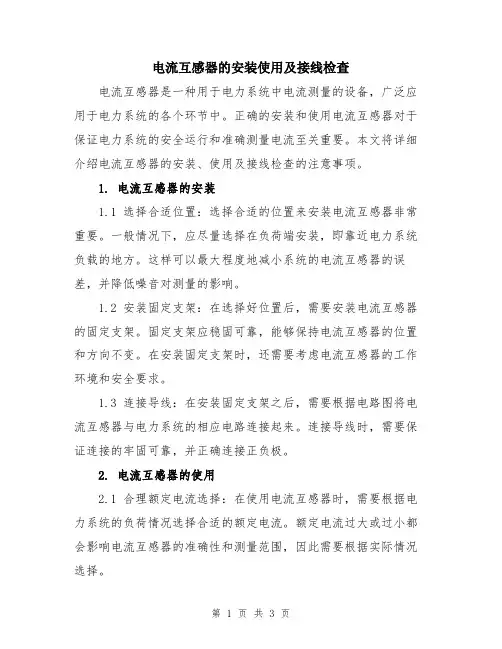
电流互感器的安装使用及接线检查电流互感器是一种用于电力系统中电流测量的设备,广泛应用于电力系统的各个环节中。
正确的安装和使用电流互感器对于保证电力系统的安全运行和准确测量电流至关重要。
本文将详细介绍电流互感器的安装、使用及接线检查的注意事项。
1. 电流互感器的安装1.1 选择合适位置:选择合适的位置来安装电流互感器非常重要。
一般情况下,应尽量选择在负荷端安装,即靠近电力系统负载的地方。
这样可以最大程度地减小系统的电流互感器的误差,并降低噪音对测量的影响。
1.2 安装固定支架:在选择好位置后,需要安装电流互感器的固定支架。
固定支架应稳固可靠,能够保持电流互感器的位置和方向不变。
在安装固定支架时,还需要考虑电流互感器的工作环境和安全要求。
1.3 连接导线:在安装固定支架之后,需要根据电路图将电流互感器与电力系统的相应电路连接起来。
连接导线时,需要保证连接的牢固可靠,并正确连接正负极。
2. 电流互感器的使用2.1 合理额定电流选择:在使用电流互感器时,需要根据电力系统的负荷情况选择合适的额定电流。
额定电流过大或过小都会影响电流互感器的准确性和测量范围,因此需要根据实际情况选择。
2.2 避免过载:在使用电流互感器时,应避免超过额定电流的过载情况。
过载会导致电流互感器的过热和损坏,影响正常工作。
2.3 定期检测和校准:为了保证电流互感器的准确性,需要定期对电流互感器进行检测和校准。
检测和校准应由专业人员进行,确保测量结果的准确性。
3. 电流互感器的接线检查3.1 安全检查:在进行接线检查之前,首先要进行安全检查,确保工作环境安全,并采取相应的防护措施。
3.2 接线检查:接线检查时,需要逐一检查电流互感器的各个接线点是否连接正确,是否松动或损坏。
接线点应保持干净,无腐蚀和氧化。
3.3 接地检查:电流互感器的接地是非常重要的,可以提供额外的安全保护。
接地线应连接牢固,并确保良好接地。
3.4 箱体检查:电流互感器的外壳应无裂纹或破损,并保持干净。
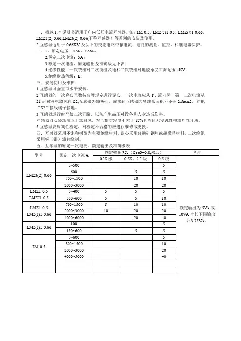
一.概述;1.本说明书适用于户内低压电流互感器,如:LM-0.5,LMZ(J)1-0.5,LMZ(J)1-0.66,LMZ3(2)-0.66,LMZ3(2)-0.66(下称互感器)等系列的安装及使用。
2.互感器适用于0.66KV及以下的交流电路中作电流、电能的测量、监控、和继电器保护。
二.1。
额定电压:0.5kv~0.66kv;2.额定二次电流:5A;3.额定一次电流、额定输出及准确级见下表:4.绝缘性能:一次绕组对二次绕组及地和二次绕组对地能承受工频耐压4KV.5.绝缘耐热等级:E.三.安装使用及维护1.互感器可垂直或水平安装。
2.互感器的一次穿心匝数按名牌规定进行穿心,一次电流应从P1流向另一端,二次电流从S1经过外电路流向S2,互感器为减极性,连接到互感器的导线截面积不小于2.5mm2,并把“S2”接线端子接地。
3.互感器运行时严禁二次开路,以防产生高压对设备和人身造成伤害。
互感器的安装场所应干燥通风,空气相对湿度不大于80%且周围无侵蚀性和爆炸性介质。
5.互感器要周期性检定,对检定不合格的应进行维修或更换。
四.互感器采用不饱和树酯为主要绝缘材料,铁心采用普通硅钢片或超微晶材料,二次绕组采用铜(铝)漆包绕制。
五.互感器的额定一次电流、额定输出及准确级表型号额定一次电流A额定输出V A(CosØ=0.8,滞后)备注0.2S级0.5S、0.2级0.5级额定输出为5V A或10V A时其下限输出为3.75V A。
LMZ3(2)-0.665~500 5 600 5 5 750~1500 10 10 2000~3000 20 20LMZ1-0.5 LMZJ1-0.55~400 5 5 5 500~600 5 5 10LMZ1-0.5 LMZ(J)1-0.66 750~1500 5 10 10 2000~3000 10 20 20 4000~6000 20 40LMZ(J)1-0.66100 5 150~600 5 5LM-0.55~600 5 800~1500 10 2000~3000 20 4000~5000 40。
电容式电压互感器安装使用说明书编号:0TK.466.8926泰开集团山东泰开互感器有限公司2010年04月本使用说明书介绍了该产品的使用用途、使用环境、基本性能以及产品的运输、使用和维护。
1. 概述电容式电压互感器在频率为50Hz的高压及超高压电力系统中,接到线与地之间为电气测量仪器、仪表和保护、控制装置提供电压信号并可兼作电力线路载波耦合装置中的耦合电容器。
1.1 产品型号含义1.2 使用条件互感器为户外装置,安装运行地区的周围空气温度为-40~+55℃,海拔不超过2000m(海拔超过2000m的产品,根据用户和厂方双方协商,按用户的要求另行制造),风速不大于150km/h,地震烈度不超过8度,无严重污秽、震动和颠簸。
2. 主要规格及参数2.1 互感器可在1.2倍额定电压下长期运行;用于中性点有效接地系统的互感器可在1.5倍额定电压下运行30s。
用于无自动切除对地故障的中性点非有效接地系统的互感器可在1.9倍额定电压下运行8h。
2.2 中间变压器绕组的连接组为1/1/1/1-12-12-12或1/1/1-12-12。
2.3 互感器型号中带“H”的产品爬电比距≥25mm/kV(按系统最高电压计算)。
2.4 互感器绝缘水平见表1。
(以铭牌参数为准)2.5 互感器的准确级及相对应的电压误差和相角差及工作条件见表2。
2.6 电容分压器的载波耦合电容C及高压电容C1和中压电容C2的电容偏差应不超过其额定值的-5%~+10%,而C1 及C2两者偏差之差不超过5%。
2.7 电容分压器的介质损耗角正切值不大于0.0015。
2.8 互感器符合GB/T4703《电容式电压互感器》、JB/T19749《耦合电容器及电容分压器》、JJG314《测量用电压互感器》、IEC60044-5的要求。
2.9互感器主要技术参数见表3。
表1 互感器绝缘水平kV表2 互感器工作条件及误差限值3. 产品结构和工作原理3.1 产品结构本产品由电容分压器和电磁单元两部分组成。
电流互感器的安装使用及接线检查模版电流互感器是电力系统中常见的一种装置,用于测量电流的大小。
它广泛应用于变电站、配电系统等电力设备的安装和维护中。
以下是电流互感器的安装使用及接线检查模板,供参考使用。
一、电流互感器的安装1. 安装位置选择:根据实际需要选择电流互感器的安装位置,通常应选择在电力设备运行稳定的位置,离电源和负荷较近,并保证容易安装和维护。
2. 确定安装方式:根据电流互感器的型号和规格,确定合适的安装方式,可以选择侧面安装、上面安装等方式。
3. 安装固定支架:根据电流互感器的安装要求,选择合适的固定支架,并通过螺栓或其他固定装置将其牢固地安装在所选位置上。
4. 安装导线连接:根据实际需要,选择合适的导线连接电流互感器的绕组。
将导线连接到电流互感器的引线端子上,并牢固地固定。
5. 安装绝缘保护:在电流互感器的绕组和导线连接处,应添加绝缘保护措施,以防电流互感器受到外界的损坏和干扰。
二、电流互感器的使用1. 连接设备:将电流互感器的引线分别连接到电力设备的进线和出线上,保证连接牢固且绝缘良好。
2. 调整初始值:在初次使用电流互感器时,应根据实际需要调整其初始值,以满足电流测量的要求。
3. 运行监测:电流互感器正常使用后,应定期进行运行监测,检查其测量精度和运行状态,如发现异常情况应及时处理。
4. 维护保养:定期对电流互感器进行维护保养,清除灰尘和污垢,检查绝缘情况,并及时更换损坏的部件。
三、电流互感器的接线检查模板1. 接线部分:(1)检查电流互感器的导线是否牢固连接,无松动、脱落现象。
(2)检查电流互感器引线末端的绝缘套管是否完好,无破损、老化现象。
(3)检查电流互感器引线末端的接线端子是否干净、无尘污、氧化现象。
2. 绝缘部分:(1)检查电流互感器绕组和引线之间的绝缘情况,无破损、裂纹、腐蚀现象。
(2)检查电流互感器绕组和外壳之间的绝缘情况,无破损、裂纹、腐蚀现象。
(3)检查电流互感器绕组和周围金属设备之间的绝缘情况,无短路、漏电现象。
电流互感器的安装使用及接线检查电流互感器(CT)主要用于测量或保护系统中的电流。
它可以将高电流传感到低电流状态下,以便进行监控、测量和控制。
本文将详细介绍电流互感器的安装、使用和接线检查。
1、安装:1.1、选择安装位置:电流互感器应安装在电流测量回路中的合适位置。
一般来说,最佳位置是在电缆或导线的近端,以便准确测量电流。
同时还需要考虑到线路的安全性和防护等级要求。
1.2、安装方法:电流互感器通常有两种安装方法,分别是直流式和带制动器的回路。
直流式安装适用于小功率或不短时过载的电流测量,而带制动器的回路则适用于大功率或短时过载的电流测量。
1.3、安装注意事项:在安装电流互感器时,需要注意以下几点:①、避免电流互感器与其它金属或电缆的接触,以免产生干扰或损坏设备。
②、保持电流互感器的通风良好,并避免长时间暴露在高温环境中。
③、确认电流互感器的安装位置与使用要求相符,避免安装位置导致测量误差。
2、使用:2.1、接线方法:电流互感器的接线需要严格按照产品说明书进行,通常分为两种接线方式:直流接线和交流接线。
直流接线一般用于直流回路中,交流接线用于交流回路中。
2.2、注意事项:①、确认电流互感器的额定电流和频率,并与实际电流和频率相匹配。
②、检查接线是否牢固,并保持接线干净。
③、在进行交流接线时,应注意线圈相序的正确连接,以避免测量误差。
④、定期检查电流互感器的接线,确保接线的可靠性。
3、接线检查:3.1、外观检查:定期检查电流互感器的外观,包括外壳是否有损坏、螺丝是否松动等。
如发现问题,应及时修理或更换。
3.2、连接检查:检查电流互感器的接线是否牢固,没有松动或断裂。
同时,还要检查接线端子是否与导线良好接触。
3.3、测量检查:使用合适的电流表或多用表检查互感器的输出电流是否与实际电流相符合。
如发现测量误差较大,可能是接线不良或互感器损坏。
3.4、环境检查:检查电流互感器所处环境的温度、湿度是否符合使用要求。
电流互感器的安装使用及接线检查范本一、电流互感器的安装使用1. 安装位置选择电流互感器的安装位置选择应考虑以下因素:(1) 电流互感器应安装在电流变送器附近,以便方便进行接线。
(2) 避免长时间暴露在阳光直射下。
若无法避免,应选择耐候性好的电流互感器。
(3) 要避免安装在易受冲击或振动的位置,以免损害电流互感器的精度和可靠性。
(4) 确保电流互感器安装时方向正确,应遵循产品说明书或相关标准。
(5) 要根据电流互感器的额定容量选择合适的安装位置,并确保其能够无妨碍地通风散热。
2. 安装注意事项(1) 在安装电流互感器之前,必须切断电流回路供电。
在接线检查完毕后,方可通电操作。
(2) 使用电流互感器时,应提前做好接地措施,以确保人身安全。
(3) 进行接线时,应根据电流互感器的接线图正确连接,确保接线的可靠性和正确性。
(4) 在接线检查过程中,应仔细检查接线螺母是否紧固,接线端子是否松动或接触不良,以免影响电流互感器的工作性能。
二、电流互感器的接线检查范本1. 检查前准备(1) 首先,确保电流互感器与变送器之间的连接线良好连接,并处于正常工作状态。
(2) 其次,确认电流互感器和其他电气设备的接线端子是否紧固。
如有锈蚀或松动现象,应及时清理和修复。
(3) 确认电流互感器接线端子的标识是否清晰可辨,以便正确接线和检查。
2. 接线检查步骤(1) 检查电源接线:将电流互感器的电源线与电源端子相连,确保接触良好。
(2) 检查变送器接线:将电流互感器的输出信号线与变送器的输入端子相连,确保接触牢固。
(3) 检查设备接线:将变送器的输出信号线与显示仪表或控制系统的输入端子相连,确保接线正确。
3. 接线检查注意事项(1) 在进行接线检查之前,务必切断电源,以免发生电击事故。
(2) 接线检查时应仔细观察接线端子的状态,如发现松动、脱落、氧化等异常情况,应及时处理。
(3) 检查完毕后,应按照正确的顺序通电,并观察电流互感器及其连接设备的工作状态是否正常。
互感器安装作业指导书互感器安装作业指导书一、前言互感器是电力系统中常见的一种变压器,主要用于实现高压与低压之间的能量转换和电流测量。
互感器在电力系统中的应用非常广泛,涉及到电力传输、配电、变电等多个环节。
本文将为相关人员提供互感器安装作业指导书。
二、准备工作1.检查互感器的规格、型号和数量是否与订单一致;2.配备必要的工具,如扳手、螺丝刀、气动工具等;3.检查现场安装环境是否符合安装要求,特别注意周围环境油污、潮湿等;4.准备好保护措施,确保人员安全进行操作。
三、安装步骤1.根据安装要求,先进行现场勘测,确定互感器的安装位置和方向;2.在互感器安装位置标出安装孔位置,用钻头和锤子将孔打好;3.将互感器安装板或支架安装在墙或柱子上,并请注意固定螺丝是否松动;4.将互感器依据安装方式及孔位尺寸固定在安装板或支架上;5.连接互感器与绝缘杆、衔铁,确保连接牢固,紧固螺栓并进行相关接线;6.接下来要进行绝缘测试,确保绝缘性能良好,满足使用要求;7.对互感器进行调试,检查互感器是否有损伤或松动现象;8.清理好现场,使得现场环境整洁无障碍。
四、注意事项1.安装过程中,应注意现场的安全,确保人员不受伤害;2.在操作过程中,应特别注意防止互感器遭受外界撞击和损坏;3.互感器安装后,应及时进行绝缘测试和功能测试,确保互感器的正常使用;4.安装完毕后,应及时清理现场,并修复现场损伤。
五、结语本文为互感器安装作业的指导书,内容详细、操作简单明了。
在互感器的安装过程中,务必注意安全,万无一失,确保互感器正常运行,提高其使用寿命。
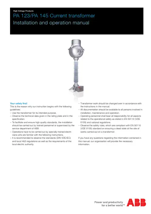
PA 123/PA 145 Current transformer Installation and operation manualYour safety first!This is the reason why our instruction begins with the following guidelines:−Use the transformer for its intended purpose.−Observe the technical data given in the rating plate and in the specification.−To facilitate and ensure high quality standards, the installation should be carried out by trained personnel or supervised by the service department of ABB.−Operations have to be carried out by specially trained electri-cians who are familiar with the following instructions.−It is recommended to observe the standards (DIN VDE/IEC) and local H&S regulations as well as the requirements of the local electric authority.−Transformer work should be changed over in accordance with the instructions in the manual.−All documentation should be available to all persons involved in installation, maintenance and operation.−Operating personnel shall bear all responsibility for all aspects related to the operational safety as stated in EN 50110 (VDE 0105) and national regulations.−Observe the safety rules, which are compliant with EN 50110 (VDE 0105) standard on ensuring a dead state at the site of works carried out on a transformer.If you have any questions regarding the information contained in this manual, our organisation will provide the necessary information.Important informationThis manual is intended to explain the mode of operation andinstallation of the product.Operating the device without reading the manual may entail prop-erty damage, serious injury or death. The person responsible for the installation of the device should read the following instructions and follow the recommendations contained herein.For your own safety:−Make sure that all installation, service and maintenance works are performed by professionals.−Make sure that during all the phases (installation, service, up-keeping) all applicable regulations will be preserved.−Ensure that the guidelines contained in this manual are followed.Basic guidelines for this manualRead the relevant chapters of this manual to provide adequate operation. Chapters are marked according to their significance.2 PA 123/PA 145 Current transformerTable of contents1. Introduction (4)2. Transformer delivery (4)3. Transportation, unpacking, lifting (4)4. Storage (5)5. Installation (5)5.1. Earthing terminals (5)5.2. Primary terminals (5)5.3. Secondary terminals (5)6. Bolt tightening torques (6)7. Operation and maintenance (6)7.1. Operation (6)7.2. Corrosion protection (8)8. Transformer construction (8)9. Disposal (9)9.1. Recycling and disposal proceedings (9)10. Check list (10)10.1. Before first energising (10)10.2. After first energising (10)11. End (11)PA 123/PA 145 Current transformer 3PA 123/PA 145 Current transformer1. IntroductionThe subject of this manual are type PA 123 and PA 145 overhead current transformers. These transformers are used for feeding measurement and protection systems in power networks with maximum system voltage of 123 kV and 145 kV or lower (the greatest effective value of phase-to-phase voltage) and 50 Hz fre-quency. They are designed either to operate in grids with effectively earthed or insulated neutral points or in compensated networks.2. Transformer deliveryTypically, the transformers are delivered in bulk packaging (3 pcs) where they are stacked vertically. The packaging is in the form of a complete crate.The delivered transformers are fully assembled, tested and ready for direct use. Product testing protocols are delivered together with the transformers.Immediately after delivery, check whether the transformer has not been damaged during transportation. Check the transport pack-aging. Damaged packing may point out to careless handling of the transformer. Next, check the transformer itself. Special atten-tion should be paid to possible damage of sheds and binder at insulator flanges, to the tightness of the transformer and the cor-rect oil level indication in the device.One should ensure that technical parameters of the transformer given in the rating plate are in accordance with the parameters given when submitting the order and in accordance with the design documentation parameters.Any damage found or other error should be immediately notified to the manufacturer, and, if appropriate, the carrier. Sending pho-tos of damage will be helpful in its assessment.3. Transportation, unpacking, liftingTransformers may be transported in either vertical or horizontal position.In the case of horizontal transportation, transformers should be transported on a special bed in accordance with the method as shown in Figure 1. Additionally, before laying the transformer, restrain its compensation bellows by inserting a flexible disc made of, for example, polyurethane foam, under the bellows cover. Dur-ing horizontal transportation, the compensation bellows cannot have any freedom of movement due to their flexibility and possibil-ity of damage.In vertical transportation, due to the high position of the centre of gravity, the transformer should be transported on arms or plat-forms expanding spacing of the base. Those elements shall be removed before setting the transformer on the support structure (in the working location).Transformers should be lifted with a crane with appropriate load capacity using two slings of the same length (min. 1.5 m). Hooks should be attached to the openings designed for that purpose located in the transformer head enclosure (see Fig. 1).Packing method for horizontal transformer transport4 PA 123/PA 145 Current transformer4. StorageTransformers should be stored on a levelled and hardened surface, preferably in the original packaging. In the case of long-term storage, it is recommended to protect contact surfaces against corrosion.Transformers can be stored in the open air for up to two years. If this period is exceeded, it is recommended to place transformers in a well-ventilated room or under a roof, and to insert silica gel or another moisture absorbent into terminal boxes.5. InstallationThe support structure should be flat and horizontal. Levelling correction can be performed using distance washers, placing them between the transformer and the structure. Observe the notes given in item 3 while shifting the transformer. It should be fastened to the structure with screw elements of an adequate size. The support structure and fastening elements are not included in the delivery.The transformer should be placed in the vertical position at least 24 h before energising.5.1. Earthing terminalsTwo earthing terminals are found on the base of the transformer across its diagonal. Prior to connection, the contact surface of the terminals should be thoroughly cleaned from oxide layers so it becomes uniform and smooth. Additionally, a thin layer of con-ducting grease can be applied in order to improve contact. The earthing should be connected with stainless bolts.5.2. Primary terminalsPrimary terminals of the transformer, marked as P1 and P2, are placed on the opposite sides of the head. In the case of recon-nectable transformer, up to 3 P2 terminals can be found on the primary side, marked with respective values of the rated primary current.Reconnection of the primary winding to the required current range is performed by placing a detachable terminal (bolt or flat) in the location marked with the respective current value. These terminals should be fastened to the transformer with four supplied M12 bolts. Contact surfaces should be cleaned beforehand.All contact surfaces of the primary terminals should be even and cleaned from the oxide layer before connecting. In the case of copper terminals, use of extraction naphtha is usually sufficient. Conducting grease can be applied in order to improve contact. The line cable terminals should be tightened with M12 bolts (stainless bolts are recommended) to such prepared terminals. An incorrectly performed primary connection will lead to excessive heating of the transformer, which can cause its damaging. Primary connections should be made in such a way so as to minimise mechanical static loads of the transformer terminals. It is recom-mended to use flexible elements as rigid connections may cause damage of the transformer. The maximum allowable static load of each transformer terminal is equal to 3,600 N in any direction. At the same time, only one terminal can be loaded with such force. Also, it is recommended to maintain the sum of the loads acting on the primary terminals during normal operation of the trans-former below 50% of such a value.5.3. Secondary terminalsSecondary windings are connected to terminal blocks placed in the terminal box on the bottom of the transformer. These are typi-cally Phoenix ST spring connectors with terminals adapted to connection of cables of cross-section up to 10 mm2 or up to 6 mm2. Each terminal is described in accordance with winding markings given on the rating and schematic diagram plates. Yellow-green terminals (with the earthing mark) are intended for earthing secondary windings with the use of pushed crosswise bridges. The crosswise bridge can be removed with a screwdriver, by inserting it in the slit and levering.Optionally, the connectors to which metering windings are led may be adapted for sealing with use of a transparent cover.The current coil screen is led out with a pin through the resin bushing (tg δ terminal).A rating plate is placed on the external side of the door, while the schematic diagram plate is placed inside.In the bottom wall of the terminal box, there is a plate with open-ings for glands for secondary circuits’ connection cables. In the typical execution, they are two M40 glands with the choking range of Ф19 mm – Ф28 mm.An example of a terminal box for secondary windings of the trans-former is shown in Figure 2.PA 123/PA 145 Current transformer 56 PA 123/PA 145 Current transformerConnect external circuits to secondary terminals of the voltage module of the transformer pursuant to the design documents and wiring shown on the schematic diagram plate.The current coil screen terminal (tg δ) should be earthed with a jumper during normal transformer operation.Connectors inside the terminal box are arranged so that, when using crosswise bridges, earthing is possible for any secondary terminal of a given winding.−Transformer with taps on the secondary side:In the case of a transformer with reconnection on the secondary side, unused taps should remain unearthed, and only one of the terminals, to which circuits are connected for a given secondary winding, should be earthed. −Unused windings:Utmost terminals (with reconnection on the secondary site, these are terminals corresponding to the highest ratio) of the unused secondary winding should be shorted with each other (with a cable of minimum cross section of 6 mm 2) and earthed with a crosswise bridge. Each unused winding should beearthed in only one point.6. Bolt tightening torquesPrimary terminal bolts M1260 Nm Bolts fastening the transformer to the support structure280 Nm7. Operation and maintenance7.1. OperationTransformers do not require special servicing. Visual inspection is usually sufficient. The check-list is placed at the end of this manual.Visual inspection:Visual inspection should be based on:−the position of the oil level indicator,−tightness of the transformer,−lack of mechanical damage,−condition of the insulator and binder connecting the insulator with flanges.Occasionally, check the tightening degree of the primary terminals.The transformer tightness is a particularly important criterion as in the case of oil leaks moisture can penetrate the device. Small insulator damage may be repaired on site.Oil level indicator:Changes of the position of the oil level indicator depend on oil temperature in the transformer. The position of the indicator should be in the green field range. Shifting of the indicator to the upper or bottom red field points out to incorrect transformer oper-ation. In such a case, the transformer should be put out of service, and the manufacturer should be contacted.On the lid covering the head stainless steel expansion bellows (1) are placed, used for compensation of oil volume thermal changes in the transformer. The oil level indicator (2) is placed on the upper surface of the bellows. The bellows are placed in a metal cover (3) equipped with a view-finder (4). Cover removal does not result is unsealing of the transformer. The whole compensation system is shown in Figure 3.Position of the oil level indicator Interpretation Indicator in the green area Correct transformer operationIndicator on the upper red fieldOil pressure too highTransformer over heatingOil gasification(insulation failure)Further inspection necessary Indicator on the lower red fieldOil level too lowSuspicion of oil leakage (moisturemay penetrate inside)Further inspection necessaryMeasurement of the dielectric loss factor tgδ:During measurement of the dielectric loss factor tg δ, the measur-ing bridge should be connected to the correct terminal marked with the tg δ symbol. One should remember to earth it after per-forming the measurement. Usually, the test voltage should equal 10 kV RMS, and it should be applied across transformer primary terminals and earth.1243Fig. 3. Construction of the compensation systemPA 123/PA 145 Current transformer 78 PA 123/PA 145 Current transformerOil sampling:Due to the fact that transformers are air-tight, they do not require periodical oil checking. Oil used in the transformer meets the requirements of the PN-EN 60296 (IEC 60296) standard.It is recommended to check the oil after 15–20 years of operation or after a non-conformity state if there are suspicions as to trans-former efficiency.Contact the manufacturer in order to obtain necessary instructions concerning oil sampling. If oil samples are taken during the guar-antee period without the manufacturer’s permission, the device loses its guarantee.7.2. Corrosion protectionExternal elements of the transformer casing are made in the form of aluminium alloy casts, resistant to corrosion. Casts can be unpainted or painted. Typical colours in the case of painted casts include light-grey (RAL 7035) or grey-green (RAL 7033). While remaining metal elements, such as bolts, are made of stainless steel.8. Transformer constructionPA 123 or PA 145 type current transformer comprises a current coil in a tight enclosure filled with transformer oil.This is a "top core" type structure where the magnetic toroidal cores are located in the transformer head. The cores withsecondary windings are additionally encapsulated in a metal can connected via a tube to terminal box tg δ terminal. Both the metal can as well as the tube are insulated with oil impregnatedelectrical grade paper. The distribution of electric stresses in the paper insulation is capacitor controlled. En exterior screen is located external to the coil, connected to the primary terminal inside the head.Such a coil structure provides the following advantages:protection of devices connected to the terminal in the event of primary insulation perforation, equalisation of electrical stresses in primary insulation and a facility for measuring the tg δ coefficient on the primary insulation only.Fig. 4. PA 123 and PA 145 current transformers structure 1. base2. hollow insulator3. head4. e xpansion bellows in casing5. opening coil6. s econdary coils terminal box7. P2 primary terminals8. P1 primary terminal9. m ounts for fastening thetransformer 10. h oles for lifting the unit 11. oil level indicator1234567981011The transformer primary insulation constitutes electric grade paper dried at a high temperature and high vacuum impregnated with transformer oil. The free spaces inside the transformer are filled with transformer oil.External insulation comprises a hollow insulator made out of elec-trical porcelain with brown enamel or a glass reinforced plastic (FRP) tube coated with grey silicon rubber.The seals in the transformer are of the o-ring type, and they are made of NBR oil-resistant rubber.If calibration of measuring windings has been performed, addi-tional respective markings (designations) have been placed on the transformer and the rating plate (where required).9. DisposalDuring correct operation and when no mechanical damage occurs, the transformer should operate over 30 years. Once this period of time has expired or if operation is no longer required, it is recommended to dispose of the transformer.Primary materials used in the transformer:Item Material Quantity [kg] 1Copper (Cu – ETP)20 2Aluminium alloy AC-Al Si10Mg (Cu)80 3Steel20 4Transformer plate50 – 150 5Permalloy (iron-nickel alloy)10 6Mineral transformer oil120 7Electrical grade paper25 8Solid insulation materials (epoxy resin, bakelitepaper)10 9Porcelain80 10Composite insulator20 Items 9 and 10 alternatively.Above values are approximate.9.1. Recycling and disposal proceedingsRecycling and disposal should meet national (or local) regulations. On the territory of the Republic of Poland, the manner by which the transformer should be recycled and disposed is defined in the Waste Act of 14 December 2012, published in Journal of Laws, 2013, item 21, as amended.PA 123/PA 145 Current transformer 910. Check list10.1. Before first energisingWhat to check:When Check: 1. E xternal packing appearance A No signs of careless handling2. Transformer tightness A, B, CNo visible oil leaks or greasy stains (even if the packing is intact)3. Transformer housing B, C Insulator, terminals and housing of the transformer show no signs ofmechanical damage.4. Oil level B, C Oil level indicator is in the proper position5. Quality and correctness of performed connections C Performed connections are reliable and in accordance with the design10.2. After first energisingWhat to check:When Check: 6. Transformer tightness D, E No visible oil leaks or greasy stains7. Transformer housingD, E Insulator, terminals and housing of the transformer show no signs of mechanicaldamage.8. Oil level D, E Oil level indicator is in the proper position9. S econdary winding insulation test (measurement methoddepends on local practices)E Values dependent on age, voltage level, measurement method and temperature10. D ielectric loss factor tg δ (measurement method dependson local practices)E Values dependent on age, voltage level, measurement method and temperatureRespective terminals are marked as: …tg δ”11. O il sampling: gas analysis (DGA), tg δ, water content EMeasurements did not indicate exceeding of permissible limitsWhenA After arrival of the transformer to the final locationB After unpackingC Directly before applying voltageD During routine inspection in accordance with the schedule determined for the stationE After 15–20 years or inspection of efficiency after the non-conformity state if there are suspicions as to transformer efficiency11. EndFor additional information concerning the operation and mainte-nance of type PA 123 and PA 145 transformers, please contactthe transformer manufacturer.10 PA 123/PA 145 Current transformerNotesPA 123/PA 145 Current transformer 112129P L 969-W 1-e n . E d i t i o n 01.2014For more information, please contact:ABB Contact Center Phone: +48 22 22 37 777e-mail:**************.comABB Sp. z o.o.Branch Office in Przasnysz ul. Leszno 5906-300 PrzasnyszPhone: +48 22 22 38 931, +48 22 22 39 255 Fax.: +48 22 22 38 958www.abb.plWe reserve the right to make technical changes or modify the contents of this document without prior notice. With regard to purchase orders, the agreed particulars shall prevail. ABB Sp. z o.o. does not accept any responsibilitywhatsoever for potential errors or possible lack of information in this document.We reserve all rights in this document and in the subject matter and illustrations contained herein. Any reproduction, disclosure to third parties or utilisation of its contents – in whole or in parts – is forbidden without prior written consent of ABB Sp. z o.o.© Copyright 2014 ABB All rights reserved。
JING KE40.5 〜550kVSF6电流互感器安装、运行、维护使用说明书M C13000001中国江苏精科智能电气股份有限公司1.适用范围和产品用途1.1适用范围本安装使用说明书对SF6电流互感器的使用条件、技术参数、产品结构、交接、安装、使用与维护等方面作出了具体规定,敬请您在安装之前详细阅读。
1.2产品用途本公司制造的SF6电流互感器适用于额定电压分别为35、110、220、500kV,额定频率为50Hz的交流电力系统中作电流、电能计量、测量及母差保护、过流保护、距离保护等作用。
1.3型号说明如220kV SF6气体绝缘电流互感器:L V Q B T --- 252(220)(GY)W2(3)」皿级防污(W级防污)咼原型设备最高电压(额定电压)kV -------------------- 带暂态保护绕组稳态保护气体绝缘--------------------------------------------- 倒置式结构电流互感器2.使用条件2.1设备种类户外2.2环境温度最高温度+45 C日平均最高温度+35 C2.3海拔<2000m (特殊产品不超过3500m )2.4 大气条件 大气中无严重影响互感器绝缘的污秽、侵蚀性和爆炸性介质2.6 最大风速35m/s8 度(水平加速度 0.25g 、垂直加速度 0.125g ) 1.673. 技术参数设备最高电压: 40.5、126、252、550 kV 额定电压: 35、110、220、500kV额定一次电流:100 〜5000、2 X50 〜2 X 2000 A(500kV 产品可满足w 2 X 5000 A ) 额定二次电流:1 、 5 A额定负荷:20 /准确限值系数: 100VA 10 〜 40 仪表保安系数: FS5、 FS10测量绕组的准确级: 0.2S 、0.5S 、0.2、0.5 稳态保护绕组的准确级: 5P 、10P 、5PR 、10PR 暂态保护绕组的准确级: TPS 、 TPY二次绕组个数: 1〜8个各准确级的误差限值见 GB1208 — 2006《电流互感器》、GB16847-1997《保 护用电流互感器暂态特性技术要求》 。
互感器安装标准化作业指导书1. 引言互感器是一种用于测量电流、电压和功率的重要装置,广泛应用于电力系统、工业生产和科学研究领域。
为了保证互感器的安装质量和性能,制定互感器安装标准化作业指导书对于确保电力系统的安全运行至关重要。
2. 安装前的准备工作在安装互感器之前,需要进行一些准备工作,以确保安装的顺利进行。
首先,应仔细阅读互感器的安装说明书,并对安装位置进行评估和测量。
其次,需要准备安装所需的工具和材料,如螺丝刀、扳手、螺栓、螺母等。
3. 安装位置的选择选择合适的安装位置对于互感器的正确运行至关重要。
一般来说,应选择距离被测电源或设备适当距离的位置。
同时,还需要考虑互感器与电源之间连接线的长度,以确保信号传输的准确性。
此外,还需要考虑安装位置的环境条件,如温度、湿度等。
4. 安装步骤(1)固定互感器:将互感器放置于选择好的安装位置,并使用合适的固定装置将其固定在电源或设备上。
确保固定牢固,以防互感器在使用过程中出现移位或松动。
(2)连接线路:根据互感器的类型和规格要求,选择合适的电缆进行连接。
首先,将互感器的引线与电缆连接头进行固定连接,然后通过接线盒将互感器与电源或设备的电路连接起来。
确保连接线路的接触良好,绝缘良好。
(3)校准调试:安装完毕后,需要对互感器进行校准和调试,以确保其输出信号的准确性和稳定性。
校准过程可以参照互感器的技术规范和相关标准进行操作,如用专业的测试仪器对互感器进行校准,并记录校准结果。
5. 安装后的检查和保养安装完成后,需要进行定期的检查和保养,以确保互感器的正常运行和延长其使用寿命。
每隔一段时间,检查互感器连接线路是否松动、接触不良,及时进行调整和修复。
同时,还应注意互感器周围环境的清洁和通风,避免积尘和湿度对互感器造成不良影响。
6. 安全注意事项在安装互感器过程中,需要注意以下安全事项:(1)工作时必须佩戴好合适的防护用具,避免发生电流、电压等危险。
(2)工作时要确保电源或设备已切断电源,并进行正确的接地措施。
.电容式电压互感器安装使用说明书编号:0TK.466.8926泰开集团山东泰开互感器有限公司2010年04月本使用说明书介绍了该产品的使用用途、使用环境、基本性能以及产品的运输、使用和维护。
1. 概述电容式电压互感器在频率为50Hz的高压及超高压电力系统中,接到线与地之间为电气测量仪器、仪表和保护、控制装置提供电压信号并可兼作电力线路载波耦合装置中的耦合电容器。
1.1 产品型号含义1.2 使用条件互感器为户外装置,安装运行地区的周围空气温度为-40~+55℃,海拔不超过2000m(海拔超过2000m的产品,根据用户和厂方双方协商,按用户的要求另行制造),风速不大于150km/h,地震烈度不超过8度,无严重污秽、震动和颠簸。
2. 主要规格及参数2.1 互感器可在 1.2倍额定电压下长期运行;用于中性点有效接地系统的互感器可在 1.5倍额定电压下运行30s。
用于无自动切除对地故障的中性点非有效接地系统的互感器可在1.9倍额定电压下运行8h。
2.2 中间变压器绕组的连接组为1/1/1/1-12-12-12或1/1/1-12-12。
2.3 互感器型号中带“H”的产品爬电比距≥25mm/kV(按系统最高电压计算)。
2.4 互感器绝缘水平见表1。
(以铭牌参数为准)2.5 互感器的准确级及相对应的电压误差和相角差及工作条件见表2。
2.6 电容分压器的载波耦合电容C及高压电容C1和中压电容C2的电容偏差应不超过其额定值的-5%~+10%,而C1 及C2两者偏差之差不超过5%。
2.7 电容分压器的介质损耗角正切值不大于0.0015。
2.8 互感器符合GB/T4703《电容式电压互感器》、JB/T19749《耦合电容器及电容分压器》、JJG314《测量用电压互感器》、IEC60044-5的要求。
2.9互感器主要技术参数见表3。
3. 产品结构和工作原理3.1 产品结构本产品由电容分压器和电磁单元两部分组成。
电容分压器由一节或几节电容器串联组成,高压端在电容分压器顶端。
互感器安装作业指导书作业人员共:___人工作负责人(监护人):___人吊车司机:___人安装工人:___人;由负责人指派担负相应工作,工作人员必须经考试合格,持证上岗。
(1)工作负责(监护)人职责:组织并合理分配工作,进行安全教育,督促、监护工作人员遵守安全规程,检查安全措施是否符合现场实际条件。
工作前对工作人员交代安全事项,对整个工程的安全、技术等负责。
工作结束后总结经验与不足之处,工作负责(监护)人不得兼做其他工作。
(2)工作班成员:认真学习本作业指导书,严格遵守、执行安全规程和现场安全措施卡,互相关心施工安全(1)《国家电网公司电力安全工作规程(变电所和发电厂电气部分)(试行)》(2)《电气装置安装工程电力变压器、油浸电抗器、互感器施工及验收规范》GBJ148____90(3)《电气装置安装工程质量检验及评定规程》DL/T5161.322开工前工作负责人应组织全班人员学习施工措施,检查接地线遮拦,标牌是否设置正确,清楚,并向工作班成员指明工作范围及周围带电设备。
工作班成员进入工作现场应戴安全帽,按规定着装。
服从命令听指挥,不准在现场打闹,不准超越遮拦进入运行设备。
(1)用经纬仪测量其纵、横轴与定位轴线位移应在0~5mm之内垂直度偏差小于L/10且不大于15mm。
(2)核实支架接地件及钢印号的朝向应符合设计要求。
(3)测量互感器支架相间的距离,误差为5mm。
测量互感器支架的垂直高度,误差应在0~10mm之内其同一组互感器支架测量的高度数据基本一致。
(4)测量支架柱顶板的水平度应在0~3mm范围之内。
(5)检查互感器支架的外观,镀锌层脱落涂环氧富锌漆。
镀锌排气孔封堵脱落的重新修补。
高空作业人员安全带系牢(绑扎在上方牢固点)方可作业。
施工人员上下用的梯子应置放稳固,与地面的夹角以60为宜;严禁两人站在同一个梯子上,梯子应设专人扶牢。
(1)根据施工图纸及装相单将互感器搬运到位,放置位置地基密实,搬运过程中轻吊轻放,开箱过程中,注意别损伤箱内部件。
互感器的安装方法互感器是一种用于转换某种物理量为电信号的装置,它广泛应用于工业控制、自动化、机器人、汽车电子等领域。
不同类型的互感器安装方法略有差异,下面将以压力传感器和温度传感器为例,介绍它们的安装方法。
一、压力传感器的安装方法1.选择安装位置:压力传感器的安装位置应该选在能够准确反映被测压力的位置,通常需考虑管道的内径、流速、流态及其它因素。
另外,还需要考虑安装位置是否方便维护和维修。
2.准备安装工具:在安装压力传感器之前,需要准备相应的安装工具,如扳手、螺丝刀、密封胶等。
3.准备连接件:根据安装位置和管道的规格,选择合适的连接件,如接头、法兰等。
4.安装传感器:将压力传感器安装在选定的位置上,并用螺丝固定好。
注意螺纹的方向和螺栓的紧固度。
5.连接管路:根据需要,选择合适的管路连接方式,通常需要使用阀门或接头来连接传感器和被测介质。
6.接线连接:根据传感器的接线图,将传感器与控制系统进行接线连接,确保接线正确并牢固。
7.调试验收:安装完成后,进行传感器的调试和验收工作,检查传感器的工作状态和输出信号的准确性,确保安装无误。
二、温度传感器的安装方法1.选择安装位置:温度传感器的安装位置应该选在能够准确反映被测介质温度的位置,一般应避免安装在受热或受冷的表面。
2.准备安装工具:在安装温度传感器之前,需要准备相应的安装工具,如扳手、螺丝刀、绝缘胶带等。
3.准备连接件:根据安装位置和管道的规格,选择合适的连接件,并使用绝缘胶带进行密封防水处理。
4.安装传感器:将温度传感器安装在选定的位置上,并用螺丝固定好。
注意螺纹的方向和螺栓的紧固度。
5.连接管路:根据需要,选择合适的管路连接方式,通常需要使用接头或接线盒来连接传感器和被测介质。
6.接线连接:根据传感器的接线图,将传感器与控制系统进行接线连接,确保接线正确并牢固。
7.调试验收:安装完成后,进行传感器的调试和验收工作,检查传感器的工作状态和输出信号的准确性,确保安装无误。
互感器安装作业指导书互感器是一种常用的电力测量设备,用于测量电压和电流,并将其转换为可读取和分析的信号。
在实际安装互感器时,需要遵循一定的步骤和注意事项,以确保安全可靠地进行安装工作。
下面是互感器安装作业的指导书,详细介绍了安装互感器的步骤和注意事项。
一、安装前的准备工作1. 确认互感器的技术参数和型号是否与实际使用要求相符。
2. 仔细阅读互感器的安装说明书和技术手册,了解安装步骤和注意事项。
3. 确保安装场所的环境温度和湿度符合互感器的工作要求。
4. 确保所需的安装工具和设备齐全,并进行必要的检查和维护。
5. 与现场相关人员和设备进行沟通,确定工作任务和安全措施。
二、互感器的安装步骤1. 选择安装位置:根据实际需求和技术要求,选择适合安装互感器的位置。
通常情况下,互感器应安装在电力设备的进线侧或出线侧,确保能够准确测量电流或电压。
2. 准备安装支架:根据互感器的尺寸和重量,选择合适的支架,并进行必要的加固和固定。
3. 安装互感器:将互感器按照正确的方向和位置放置在支架上,并使用螺栓或其他固定装置进行紧固。
确保互感器与支架之间的接触面积均匀,并且紧固力度适中。
4. 连接导线:根据互感器的技术要求和实际情况,选择合适的导线,并按照正确的极性连接到互感器的输入或输出端子上。
在连接导线时,确保导线端子的接触良好,并使用合适的绝缘措施。
5. 安装防护措施:根据实际需求和技术要求,为互感器安装合适的防护设施,例如防护罩、防护网等,以保护互感器免受外界环境的影响。
6. 进行接地连接:根据互感器的要求和现场情况,进行必要的接地连接,以确保安全可靠地进行工作。
接地连接应符合相关的安全标准和规范,并进行必要的测试和检查。
7. 进行测试和调试:完成互感器的安装后,进行必要的测试和调试工作,以确保互感器的工作正常。
测试和调试工作应由具有相关资质和经验的人员进行,并根据互感器的技术要求和测试要求进行操作。
三、安装注意事项1. 安装环境应符合互感器的工作要求,避免高温、潮湿或有腐蚀性气体的环境。
互感器校验软件安装说明及使用方法1.文档对象本文档说明安装,配置方法,及软件使用流程2.安装说明1)双击安装包中文件,安装程序。
2)打开Crack文件夹,然后双击Register,注册第三方组件。
3)将CRRedist2008_压缩文件打开,点击CRRedist2008_安装,即可查看报表。
3.配置说明1)运行应用程序,用户名:admin 密码:admin如下图所示2)进入程序,点击“系统管理”如下图所示3)点击“参数设置”,设置串口号,保存退出,如下图所示4.使用流程1.点击互感器校验软件图标进入 2. 运行应用程序,点击配置,如下图所示3.点击配置进入设置局编号及IP地址,如下图所示4.配置完成后点击确定,重新运行程序,用户名:admin 密码:admin如下图所示 5.点击登录进入程序,如下图所示6.准备开始实验,如做电流互感器就点击电流互感器,做电压就点击电压,做组合就点击组合,现在我以电流互感器为例具体说明一下操作步骤:点击电流互感器-→点击进入联网下载功能向导界面→输入要下载的互感器信息点击查询→找到要下载的互感器信息勾选→点击下载下载结果就会显示已下载几条,失败几条,和成功几条的信息然点击检查基本信息在点击下一步进入电流测试界面点击-→点击全程测试测试完毕后点击保存即可7.走SG186国家电网营销系统流程校验具体步骤:点击互感器测试平台→输入密码进入→点击要做的互感器信息→点击下载→输入要下载的互感器信息→勾选所要下载的互感器→点击下载→点击下一步→给互感器分配通道→点击完成→进入互感器基本信息界面核实互感器基本信息→点击下一步进入互感器测试界面→点击新量程对互感器进行测试→测试完成后点击保存即可8.不走SG186国家电网营销系统流程校验具体步骤:点击互感器测试平台→输入密码进入→点击要做的互感器信息→点击录入→输入互感器的基本信息→点击保存→然后关闭→进入脱网校验→给互感器分配通道→点击完成→进入互感器基本信息界面核实互感器基本信息→点击下一步进入互感器测试界面→点击新量程对互感器进行测试→测试完成后点击保存即可9组合互感器实验:首先录入组合互感器的各项信息,电流信息和电压信息都录入完整后点击保存,然后点击右下角的电流实验(一般先校验电流部分)然后依次点击新量程, →修改组合互感器的相别,比如AB相→全程测试。