景德镇陶瓷产业同比增长53.11%
- 格式:pdf
- 大小:106.21 KB
- 文档页数:1

碲丙毽嘏块-回复我们首先来解读一下中括号内的内容“碲丙毽嘏块”。
这是一个由四个汉字组成的组合词,每个字都代表着一个不同的含义。
下面我们将一步一步回答这个主题,探索其背后的含义。
碲(di)是化学元素周期表中的一种非金属元素,它的原子序数是52,化学符号为Te。
碲是一种银白色有金属光泽的固体,具有半导体特性。
碲也是一种重要的元素,广泛应用于电子、光学、能源等领域。
丙(bing)是一个有着多重含义的词语。
在拼音读音的解释中,丙是“bǐng”的第一个音节,它是汉字丙的拼音,也是中国传统五行中的一种火行元素。
丙也可以指代一个人的名字或姓氏。
毽(jian)是一种古老的中国传统玩具,源于汉朝,起源于民间,后成为一种正式的课外体育活动。
毽子是由带有彩色毛线的皮制袋子和用麻线包缠的皮制球组成的。
它不仅具有很高的收藏价值,还有助于锻炼人的身体协调性和反应能力。
嘏(ga)是中国方言中的一种特殊词汇,通常用于表达喜悦、满意或赞美之情。
在某些方言中,嘏也可以表示一种特殊的感激或敬佩之情。
块(kuai)是一个表示数量或块状物体的名词。
它的原义是一块切割、分裂或砍断的东西,也可以指代一块实物或一件事物的片段。
在这个主题中,我们可以看到一个混合了化学元素、姓名、传统玩具和情感表达的词语组合。
它凝聚了多个不同领域的意义,给我们提供了一个广阔的探索空间。
从化学元素的角度来看,碲作为一种半导体材料,具有重要的应用前景。
它可以用于生产太阳能电池板,以及其他光电器件和传感器。
碲的独特特性使其在电子和能源领域具有巨大潜力。
从丙这个名字或姓氏的角度来看,我们可以进一步思考与它相关的文化和背景。
丙这个字在中国五行中代表火,火与热情、温暖和活力等正面属性有关联。
这启发我们去探索丙在日常生活中的象征意义,以及与火元素相关的故事和传说。
而毽就是一个非常有趣的元素。
它作为一种传统玩具,具有悠久的历史。
我们可以从二千年前的汉朝开始,研究毽子在中国民间的流行程度和使用方式。

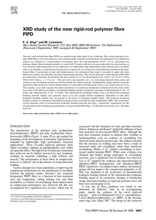
XRD study of the new rigid-rod polymer fibre PIPDE.A.Klop*and mmers †Akzo Nobel Central Research,P.O.Box 9300,6800SB Arnhem,The Netherlands (Received 2September 1997;accepted 24September 1997)The new rigid-rod polymer fibre PIPD was studied using wide angle X-ray scattering.The crystal structure of as-spun PIPD fibre can be described as a two-dimensionally ordered crystal hydrate.Its equatorial X-ray diffractionpattern was indexed to a non-primitive rectangular unit cell with parameters 16.85,3.38A˚,containing two polymer chains.Heat treatment initially (i.e.up to 300ЊC)leads to the loss of water molecules from the structure as was shown by high temperature X-ray diffraction.At sufficiently high temperatures three-dimensional crystalline order is developed,as evidenced by the presence of strong off-axis reflections in the diffraction pattern of the heat-treated fibre.A procedure of unit cell determination was introduced that made it possible to index the latter diffraction pattern and elucidate the three-dimensional packing.The crystal structure of heat-treated PIPD fibrehas monoclinic symmetry described by the space group P 21/a .Its cell dimensions are 12.60,3.48,12.01A˚,90.0,108.6,90.0Њwith r x ¼1.77g cm ¹3.The unit cell is non-primitive (Z ¼2),with chains located at the centre and corners of the rectangular projection cell describing the lateral packing.Neighbouring chains packed along thediagonals of the projection cell are shifted relative to each other in the direction of the c -axis (chain axis)by 2.0A˚.This regular c -axis shift explains the observed absence of significant meridional scattering from the lower order layer lines of the diffraction pattern.A hydrogen bonding scheme is proposed consisting of intermolecular N–H—O bonds and intramolecular O–H—N bonds.The intermolecular hydrogen bonds form a bi-directional hydrogen bonding network linking each polymer chain to its four axially shifted neighbours.Departures of the latter hydrogen bonding scheme may be present in the form of hydrogen bonded sheets.The proposed hydrogen bonding scheme is consistent with thermal expansion data provided by high temperature XRD.The monoclinic crystal structure with its bi-directional hydrogen bonding network provides a satisfactory explanation for the exceptionally good compression performance of heat-treated PIPD fibre.᭧1998Elsevier Science Ltd.All rights reserved.(Keywords:rigid-rod polymer fibre;PIPD;X-ray diffraction)INTRODUCTIONThe introduction of the polymers poly (p -phenylene benzobisthiazole)(PBZT)and poly (p -phenylene benzo-bisoxazole)(PBO)(Figure 1)some 20yrs ago marked the beginning of the development of extremely rigid polymers intended for lightweight,high performance structural applications 1.These so-called rigid-rod polymers form liquid crystalline solutions in polyphosphoric acid,which are spun into fibres.The high levels of molecular orientation thus achieved can be further increased by heat treatment,resulting in materials exhibiting a high stiffness and tenacity.The performance of these fibres in compression,however,is limited 2,due to the absence of strong interchain bonding.Various attempts have been undertaken at improving the compression performance by the introduction of crosslinks between the polymer chains.Sweeney 3has examined halogenated PBZT fibres as a function of heat treatment time and temperature,taking halogen loss and fibre insolubility as evidence of crosslinking.Some improvement in compression performance was observed,but this was accompanied by a significant loss of mass,which may beassociated with the formation of voids and other structuraldefects.Sahafeyan and Kumar 4studied the influence of post heat treatment on heat-treated PBZT fibres.Although the post heat treatment resulted in reduced fibre swelling in methanesulfonic acid,no evidence of crosslinking was observed using infrared spectroscopy.The authors conclude that the decrease in swelling may have been a result of increased order and crystallinity rather than significant crosslinking.Mehta et al .5studied crosslinking in heat-treated methyl pendent PBZT.While some evidence was obtained that methyl groups participate in crosslinking reactions,also a significant loss of methane was observed.Tan et al .6reported the synthesis and characterization of dihydroxy-PBZT homopolymer and dihydroxy-PBZT/PBZT copolymers.According to these authors,the hydroxyl groups did not improve the compression properties at all.This was attributed to the occurrence of intramolecular hydrogen bonding instead of the intermolecular hydrogen bonding aimed at.In conclusion,attempts at introducing strong interchain bonding in rigid-rod polymers have not been very encouraging so far.A way out of these problems was found in our laboratory by Sikkema 7who,in an accompanying paper,reports the synthesis of the novel rigid-rod polymer poly{2,6-diimidazo[4,5-b:4Ј,5Ј-e]pyridinylene-1,4(2,5-dihydroxy)phenylene},or ‘PIPD’,in the develop-ment stage also called ‘M5’.The design of this moleculePOLYMER Volume 39Number 2419985987Polymer Vol.39No.24pp.5987–5998,19980032-3861/98/$–see front matter᭧1998Elsevier Science Ltd.All rights reservedPII:S0032-3861(97)10187-2*To whom correspondence should be addressed†On leave from ETH Zu¨rich,Institut fu ¨r Polymere,Universita ¨tstrasse 41,CH-8092,Zu ¨rich,Switzerland(Figure1)combines the high stiffness and tenacity of the rigid-rod polymer family with extensive possibilities to form hydrogen bonds.Fibres spun from a solution of the polymer in polyphosphoric acid exhibit a higher compres-sive strength than any other polymerfibre.This unique compression performance is intimately linked to the molecular architecture of the PIPD polymer and in particular to the nature of the interchain bonding in PIPD crystallites.In the present paper we use wide angle X-ray scattering to study the structural order in PIPDfibre in order to establish the molecular basis for the outstanding compression performance.BACKGROUNDX-ray and electron diffraction were used by Roche et al.8 and Odell et al.9to determine the crystal structure of PBZT.A monoclinic unit cell was found with two chains per unit cell and with the unique axis parallel to the chain yer line streaking present in the diffraction pattern of PBZT indicates that PBZT crystallites have only two-dimensional crystalline order,i.e.the polymer chains are parallel and regularly packed but they exhibit translational axial disorder.TEM bright-field imaging indicated that limited three-dimensional order may be present10.Diffraction patterns of PBOfibre show layer line streaking indicative of axial disorder similar to PBZT. However,with increasing heat treatment the scattering becomes more localized and an off-meridian reflection on the second layer line becomes well-defined and intense. These observations point to the development of three-dimensional crystalline order in the heat-treated PBO fibre11,12.TEM bright-field lattice imaging of heat-treated PBO was reported by Adams et ing X-ray diffraction,Fratini et al.14determined a non-primitive monoclinic unit cell with two chains per cell.They proposed a model in which neighbouring polymer chains packed side by side are displaced by discrete axial translations of Ϯ1=10c andϮ1=2c(c being the unit cell axis parallel to the polymer chains).Using selected area electron diffraction Martin and Thomas12observed single crystal texturing in thin PBOfilms which made it possible to index the intense off-meridian reflection on the second layer line.This indexing,which did not coincide with that by Fratini et al.14,led to the conclusion that neighbouring chains packed side by side are shifted by random axial translations ofϮ1=4c with respect to one another,instead ofϮ1=10c andϮ1=2c.A molecular mechanics simulation of the PBO crystal structure was presented by Martin15in a study on the geometry and properties of intermolecular twist defects that may exist in extended chain polymers. EXPERIMENTALPolymerization andfibre spinningThe PIPD polymer was prepared from2,3,5,6-tetra-aminopyridine(TAP)and2,5-dihydroxyterephthalic acid (DHTA)via the TAP.DHTA1:1salt,according to the description given by Sikkema7.The salt was dissolved in polyphosphoric acid(PPA)resulting in material with h rel in the20–50range.PIPDfibres were directly spun from the polymerization solution at temperatures above160ЊC and at a concentration of18wt%PIPD in solution.The air gap spinning technique was used with a draw-down ratio in the range5–15,yieldingfilaments of about10m m diameter. After coagulation in water at room temperature,the remaining PPA was removed in a separate washing stage, and dried at mild temperatures.The as-spunfibre was subsequently heat-treated at temperatures above400ЊC for about20s under tension in a nitrogen atmosphere16.During heat treatment,the metallic blue colour of the as-spunfibre changes hardly.The PBOfibre that was used for purposes of comparison was produced according to the description in the literature1. X-ray diffractionX-ray diffraction patterns were recorded onfilm using an evacuated point-collimatedflat-plate camera(Statton)with graphite-monochromated CuK a radiation.A Siemens D5000diffractometer with a primary germanium mono-chromator was employed to measure equatorial and meridionalfibre diffraction patterns in symmetric trans-mission geometry at room temperature.Above room temperature equatorial diffraction patterns were measured using a Siemens D5000diffractometer in reflection geometry equipped with an Anton Paar HTK10hot stage. Model building and simulation of X-ray diffraction patterns were performed using the Cerius2software(version 2.0)from Molecular Simulations.The Lorentz and polar-ization corrections are included in the calculated intensities. The crystallite size,temperature factor,and the degree of arcing due to crystallite desorientation were chosen to match the observed X-ray diffraction patterns.XRD ANALYSIS OF HEAT-TREATED PIPD FIBRE Figure2a shows theflat-plate X-ray diffraction pattern of heat-treated(HT)PIPDfibre.The diffraction pattern exhibits equatorial scattering indicative of lateral packing of PIPD molecules.The polymer chains are well-oriented along thefibre axis.The crystalline perfection of PIPD fibres,like that of other rigid-rodfibres such as PBO,is considerably lower compared to the crystalline perfection of e.g.PPTAfibre,which shows a far greater number of well-defined reflections.The layer line streaking that is observedXRD study of PIPDfibres:E.A.Klop,mmers 5988POLYMER Volume39Number241998 Figure1Structural formula of PBZT,PBO and PIPDpoints to some axial disorder,a common characteristic of rigid-rodfibres.A striking and distinctive feature of the PIPD diffraction pattern is the presence of strong off-meridian reflections on thefirst three layer lines,consistent with three-dimensional crystalline order.A second dis-tinctive feature is the absence of significant meridional scattering from the low order layer lines.The investigation of the structural implications of the latter two observations will be one of the principal subjects of the present study. First,we will examine more closely the meridional diffraction pattern of HT PIPD shown in Figure3a.The fibre period c deduced from this diffraction pattern was found to be12.01A˚,the polymer chains being parallel to the c-axis.This repeat closely corresponds to the chemical repeat of the PIPD polymer as determined from model building and is identical to the repeat obtained from the meridional diffraction pattern of HT PBO also shown in Figure3a.A comparison of the diffraction patterns in Figure3a shows that the intensities of scattering are similar at higher diffraction angles,reflecting the similarity in molecular structure of the two polymers.A dramatic difference in intensity is observed in the low angle region of the diffraction patterns,where the intensity for l¼1,3, and4is much lower for PIPD than for PBO.The absence of significant scattering in this region of the meridian,already noted on theflat-plate diffraction pattern in Figure2a, suggests that the ab-plane of the unit cell of PIPD is not perpendicular to the teral crystal structureNow we will restrict our attention to the two-dimensional unit cell corresponding to the lateral packing of the polymer chains,i.e.to the projection of the three-dimensional unit cell on a plane perpendicular to the c-axis(called c-axis projection in the sequel).This projection unit cell was determined from the equatorial diffraction pattern of HT PIPD shown in Figure3b.Two strong equatorial reflections are observed at spacings of5.98A˚and3.34A˚,respectively, whereas several weak reflections are observed at smaller spacings.These reflections can be indexed on the basis of a primitive projection unit cell with parameters a¼6.22A˚, b¼3:48A˚,g¼106.2Њ,which will be referred to as unit cell I p.As the short diagonal of this unit cell is exactly equal in length to the a-axis,the reflections can also be indexed on a rectangular projection unit cell with dimensions a¼11:94A˚,b¼3.48A˚(unit cell II p).Polymer chains are located at the centre and corners of the latter non-primitive unit cell which is obtained from the former by the transformation aЈ¼2aþb(with b and c unchanged). The equatorial diffraction pattern of HT PBO(Figure3b) differs from that of HT PIPD.In contrast to PIPD,the projection unit cell of PBO is not rectangular but oblique,as is directly evident from the splitting of the3.34A˚reflection into separate110and1¯10reflections.The PBO unit cell is somewhat smaller in the a direction,as can be concluded from the smaller200spacing(5.52versus 5.98A˚). The diffraction pattern of HT PBO was indexed by Fratini et al.14to a two-chain monoclinic unit cell containing polymer chains at the(x,y)positions(0,0)and(1/2,0). After transforming the PBO unit cell via aЈ¼aþb(with b and c unchanged)so that its polymer chains are located at POLYMER Volume39Number2419985989 XRD study of PIPDfibres:E.A.Klop,M.Lammers Figure2Flat plate X-ray diffraction pattern of HT PIPDfibre,(a)observed,(b)calculated(based on the monoclinicmodel)Figure3X-ray scattering of HT PIPDfibre(bottom curve)and HT PBOfibre(upper curve)in symmetric transmission geometry,(a)meridional,(b)equatorial(0,0)and(1/2,1/2),the cell dimensions describing the lateral packing of PBO are a¼11.07A˚,b¼3.54A˚and g¼83.0Њ, which differ markedly from those of PIPD.An initial structural model of HT PIPD was constructed using the Cerius2program by placing a chemical repeat unit at the corner(s)of a primitive unit cell with dimensions a¼6.22A˚,b¼3.48A˚,c¼12.01A˚,g¼106.2Њ.In spite of the rigidity of the PIPD chain some molecularflexibility may be present in the form of limited rotation about the bond between the dihydroxyphenyl fragment and the heterocyclic fragment,i.e.the torsion angle between the two fragments may differ from zero.However,the metallic blue colour of thefibre suggests some degree of conjugation along the molecule requiring a closely planar conformation.In our initial model we started from a completely planar polymer chain which was rotated relative to its chain axis so that the calculated equatorial diffraction pattern matches the observed equatorial diffraction pattern.The model is triclinic(space group P1)and its density is calculated to be1.77g cm¹3,which is in reasonable agreement with the observed density(1.70g cm¹3)obtained via theflotation method.Note that in the model the polymer chains are not shifted relative to each other,since the ab-plane of the unit cell is simply the projection unit cell I p.Three-dimensional unit cell determinationUnravelling of the three-dimensional crystal structure of PIPD with its interchain interactions is impossible unless the general reflections(i.e.off-equator and off-meridian)can be indexed correctly.The difficulties encountered by Fratini et al.14in indexing X-rayfibre diffraction data of PBO show that it is not trivial to indexfibre diffraction patterns that exhibit only a few general reflections.Standard indexing procedures require considerably more(general)reflections than the few reflections that are actually present in the X-ray fibre diffraction patterns of PBO or PIPD.In favourable cases,additional experimental information may be obtained that simplifies the indexing procedure,such as the information provided by a selected area electron diffraction study of single crystal textured material.This information proved valuable in indexing the diffraction pattern of HT PBO as was shown by Martin and Thomas12.Unfortunately, such additional information was not available for PIPD,as single crystal textured material was not observed in a preliminary electron diffraction study17.To make matters worse(but interesting),the crystal structure of PIPD may be triclinic,as it was concluded that the ab-plane of the unit cell is probably not perpendicular to the c-axis.In the face of a possibly triclinic indexing problem with very few reflections the following procedure of unit cell determi-nation and indexing was introduced.First,the reciprocal cell parameters a*,b*and g*are deduced from the equatorial diffraction pattern.The distance d*between reciprocal lattice planes perpendicular to the c-axis is simply d*¼c¹1.Next,indices00l are assigned to a reflection on an(upper)layer line l to define the length c*of the reciprocal space vector c*[c*¼(ld00l)¹1]. The projection of c*on the reciprocal lattice plane generated by the vectors a*and b*is cءp withcءp¼cء2¹dء2p(1)Now the geometry of the reciprocal lattice is determined except for one parameter,viz.the angle n between the reciprocal space vectors a*and cءp(Figure4).Note thataء·cء¼aء·cءpbء·cء¼bء·cءpð2ÞThe reciprocal cell parameters a*and b*are obtained for a given value of the precession angle n according to the relationshipscos aء¼cءpcءcos(gءþn)cos bء¼cءpcءcos nð3Þwhich follow from the equations(2).Finally,the six reci-procal cell parameters a*,b*,c*,a*(n),b*(n)and g*are transformed to direct cell parameters a(n),b(n),c,a(n),b(n) and g(n)via inversion of the reciprocal metric tensor.As n ranges from0to360Њ,the normal to the ab-plane(i.e.c*) precesses about the c-axis(Figure4)and the vectors a and b change both in magnitude and direction but their c-axis projection does not change,since a*,b*and g*arefixed. The unit cell determination problem is now reduced to that offinding the correct precession angle n.The latter problem can be solved by matching spacings. The spacing d hkl is expressed in the parameters a*,b*,c*, g*,c*p,and n using the equations(2):1d2hkl¼h2aء2þk2bء2þl2cء2þ2hkaءbءcos gءþ2hlaءcءp cos nþ2klbءcءp cos(gءþn)(4)In general,plotting d hk1as function of n for a number of(low order)reflections hk1on thefirst layer line allows the deter-mination of the parameter n by matching the spacings calculated via equation(4)with the observed spacings (clearly,this can and should be repeated for other layer lines).As an alternative to matching spacings,the precession angle can be determined by matching diffraction patterns, i.e.diffraction patterns at different n-values are calculated and compared with the observed diffraction pattern.The latter approach was adopted in the PIPD indexing problem. Indices001were assigned to the well-defined reflection on thefirst layer line.With n ranging from0to360Њin steps of 2Њ,direct cell parameters were calculated for each value of n as outlined above.This way,a list of180unit cells,all having the same c-axis projection,is generated.For the calculation of the diffraction pattern at a particular n-valueXRD study of PIPDfibres:E.A.Klop,mmers5990POLYMER Volume39Number241998Figure4Precession of c*about the c-axisthe coordinates of the starting model are used together with the required cell parameters taken from the list.Hence,the starting model is changed systematically while keeping its c -axis projection fixed.Since the diffraction pattern changes gradually with n ,the patterns of only a small subset of the 180different n -values have to be inspected.A satisfactory match between calculated and observed diffraction patterns was found for a precession angle in the 0–4Њrange.The unit cell corresponding to n ¼2Њwas transformed according to a Ј¼a þc (with b and c unchanged)in order to have angles closer to 90Њ.Finally,with the indexing now known,the observed spacings of three strong off-axis reflections were employed to determine the tilt of the ab -plane more accurately.This resulted in thetriclinic unit cell 6.54,3.48,12.01A˚,90.0,107.9,105.4Њ(unit cell I).For reasons that will become apparent in the next section,it is advantageous to describe the structure in the c -centered unit cell with dimensions 12.60, 3.48,12.01A˚,90.0,108.6,90.0Њ(unit cell II)obtained from the triclinic unit cell after the transformation a Ј¼2a þb (with b and c unchanged).By this transformation the primitive projection unit cell I p is transformed to the rectangular projection unit cell II p of the centered cell.The resulting indexing is given in Table 1together with the observed and calculated diffraction angles.The indexing described here shows that the ab -plane ofthe unit cell is indeed not perpendicular to the c -axis as was already anticipated from the absence of low order meridional scattering.It turns out that neighbouring chains packed along the diagonals of the centered cell show anaxial shift 1/2a cos b ,or 2.0A˚,whereas the polymer chains packed face to face along the b direction do not.Final model buildingThe analysis described so far allows the construction of a triclinic model for HT PIPD.The model displays the pseudo-centrosymmetry of the PIPD molecule.The chemistry involved in the synthesis of PIPD requires that the pyridinylene-N and CH present in the PIPD repeat unit may be interchanged going from one repeat unit to the next,which implies that parallel or antiparallel packing of chains in the crystal need not be considered since N and CH are distributed randomly over two positions in the unit cell.This may be incorporated into the model by the assigning of site occupation factors 0.5to N and CH placed at both positions,after which the model will be centrosymmetrical.Note that in terms of electron density the difference between the pseudo-centrosymmetrical model and the centrosymmetrical model is so small that it does not influence the X-ray scattering intensities at all.With the unit cell parameters known,the structure is completely determined by two positional parameters,i.e.POLYMER Volume 39Number 2419985991XRD study of PIPD fibres:E.A.Klop,mmersTable 1Indexing of reflections and comparison of observed and calculated diffraction patterns of HT PIPD.The intensities are calculated based on the monoclinic model,assuming symmetric transmission geometry.The Lorentz and polarization factors are included in the calculated intensities as well as thereflection multiplicity.An overall isotropic temperature parameter of 4.0A˚2was assumed.Explanation:2v is the diffraction angle using CuK a radiation;vs ¼very strong,s ¼strong,m ¼medium,w ¼weak,diff ¼diffuse,—¼not above background (which may be streaky)2v obs (Њ)2v calc (Њ)d calc (A )h k l a I obs I calc 14.8214.83 5.974200s 489.426.6926.71 3.3381101000.029.74 3.004210vs 21.529.92 2.987400g11.445.1645.56 1.991600vw 5.446.10 1.969510g 4.252.6352.66 1.738020w–diff 29.455.4155.03 1.669220g 5.314.38 6.157¹201— 5.418.6418.85 4.709201m 17.027.16 3.283¹111—5.428.53 3.129111b10.232.8033.35 2.687401vw 7.333.47 2.678¹311g6.443.58 2.077¹601— 4.115.5615.57 5.693002w 11.517.7917.77 4.990¹202m–s 23.324.80 3.590202— 6.528.9029.00 3.079¹40225.829.80 2.998¹112m–s 7.632.27 2.774112g 10.934.57 2.594¹312— 4.544.57 2.033¹512— 4.523.3823.43 3.797¹203s–m 74.637.42 2.403¹313— 5.743.5144.12 2.052¹603 4.744.15 2.051403w–diff 6.246.02 1.972¹513g9.258.17 1.586513— 5.446.3046.60 1.949¹604vw 4.037.4437.52 2.397¹205s429.341.51 2.175¹405 6.746.22 1.964¹11512.450.49 1.808115 4.452.89 1.731¹515 4.845.3045.30 2.002¹206s–m135.253.361.717¹3166.9a The intensity of reflection h klis taken into account via the reflection multiplicity,i.e.the intensity of reflection hkl includes that of h kl bReflection 111cannot be observed due to the neighbouring strong 110reflectionthe angles of the planar dihydroxyphenyl and heterocyclic fragments with the ac -plane of the unit cell (the difference of these angles being the torsion angle between the planar fragments).The model was optimized by a combination of diffraction pattern matching (i.e.by comparing calculated diffraction patterns with the observed diffraction pattern)and energy minimization.Energy minimization was per-formed using the Dreiding II force field 18with electrostaticinteractions taken into account via Gasteiger 19charges.In the minimization the cell parameters were kept fixed.Note that optimization of the two parameters based solely on XRD data suffers from the relatively low crystalline perfection of the material which limits the accuracy of the parameters.It was found that the dihydroxyphenyl fragment is parallel to the ac -plane,whereas the heterocyclic fragment is slightly rotated.Subsequent analysis of interatomic distances suggested the presence of a hydrogen bonding scheme containing intermolecular N–H—O hydrogen bonds and intramolecular O–H—N hydrogen bonds (Figure 5).The interchain N–H—O bonds connect the shifted polymer chains,forming hydrogen bonded sheets running along one of the diagonals of the projection unit cell.The intramolecular hydrogen bonds are located between the rigid fragments and thus contribute to the rigidity of the chains.Comparing the projection unit cell of PIPD with that of PBO it is tempting to conclude that the two-chain projection unit cell of PIPD is rectangular as a result of identical interactions (i.e.hydrogen bonds)along the diagonals.This suggests that the sheet-like model needs modification,as it is not compatible with the latter conclusion (unless we assume a disorder model with sheets running on average along both diagonals).The fact that the diffraction pattern calculated on the basis of the sheet-like model closely corresponds to the observed diffraction pattern implies that the difference in positional parameters of the centre chain with respect to those of the corner chain in the two-chain unit cell must be small.This requirement and that of identical diagonals is fulfilled if the centre and corner chains are related by the monoclinic symmetry operation x þ1/2,¹y þ1/2,z ,associated with an a -glide plane perpendicular to the b -axis,instead of by the c -centering symmetry operation x þ1/2,y þ1/2,z .In the monoclinic model the same two positional parameters remain to be optimized as in the sheet-like model.The angles of the two rigid fragments with the ac -plane were found to be equal in magnitude as compared to those in the triclinic model,the only difference being that the sign of the angle of the heterocyclic fragment of the corner chain is opposite to that of the centre chain.Intermolecular distance analysis indicated the presence of a bi-directional hydrogen bonding network in which each polymer chain is linked to its four axially shifted neighbours by N–H–O hydrogen bonds (Figure 6).Intramolecular O–H–N bonds are proposed to be present between the rigid fragments similar to those in the triclinic model.The space group of the model is monoclinic,Pa (pseudo-P 21/a )with its unique axis (i.e.the b -axis)perpendicular to the fibre axis.If the random distribution of pyridinylene-N and CH is incorporated into the model we can drop the prefix ‘pseudo’,for then the symmetry requirements of the centrosymmetric space group P 21/a are fulfilled.The fractional atomic coordinates of the triclinic and monoclinic models are listed in Table 2.As the polymer chains located at the centre and corners of the projection unit cell are related by c -centering and a -glide symmetry,respectively,it is possible in principle to discriminate between the two models via the extinction rules associated with the latter symmetry elements.The c -centering opera-tion produces systematically absent reflections hkl for h þk odd,whereas a -glide symmetry generates systematic absences h 0l with h odd.Therefore,the presence of e.g.the reflection 010indicates a -glide symmetry and rules out the c -centered model.However,the relatively smallXRD study of PIPD fibres:E.A.Klop,mmers5992POLYMER Volume 39Number 241998Figure 5Triclinic model of HT PIPD showing hydrogen bonded sheets(approximately)parallel to the (1¯10)planes.The upper picture shows the polymer chains at the (x ,y )positions (0,0),(1/2,1/2),and (1,1).The polymer chains at the corners and centre are related by c -centering.Nitrogen atoms are coloured black,oxygen atoms are drawn somewhat larger to discriminate them from carbon atoms.The pyridinylene-N and -CH may be interchanged randomly。


Product Data SheetTrigonox 29-C901,1-Di(tert-butylperoxy)-3,3,5-trimethylcyclohexane, 90% solution inisododecaneTrigonox® 29-C90 is an initiator (90% active ingredient in isododecane) for (co)polymerization of ethylene, styrene, acrylonitrile, (meth)acrylates and diethylene glycol bis(allyl carbonate)-based optical monomers.CAS number6731-36-8EINECS/ELINCS No.229-782-3TSCA statuslisted on inventoryMolecular weight302.5Active oxygen contentperoxide10.58%SpecificationsActive oxygen9.31 - 9.52 %Assay88.0 - 90.0 %Color50 Pt-Co max.Hydroperoxides as TBHP≤ 0.099 %ApplicationsTrigonox® 29-C90 can be used for the market segments: polymer production, thermoset composites and acrylics production with their different applications/functions. For more information please check our website and/or contact us.Thermal stabilityOrganic peroxides are thermally unstable substances, which may undergo self-accelerating decomposition. The lowest temperature at which self-accelerating decomposition of a substance in the original packaging may occur is the Self-Accelerating Decomposition Temperature (SADT). The SADT is determined on the basis of the Heat Accumulation Storage Test.SADT60°CMethod The Heat Accumulation Storage Test is a recognized test method for thedetermination of the SADT of organic peroxides (see Recommendations on theTransport of Dangerous Goods, Manual of Tests and Criteria - United Nations, NewYork and Geneva).StorageDue to the relatively unstable nature of organic peroxides a loss of quality can be detected over a period of time. To minimize the loss of quality, Nouryon recommends a maximum storage temperature (Ts max. ) for each organic peroxide product.Ts Max.25°CNote When stored under the recommended storage conditions, Trigonox® 29-C90 willremain within the Nouryon specifications for a period of at least 6 months afterdelivery.Packaging and transportThe standard packaging is a 20 kg jerrycan. Both packaging and transport meet the international regulations. For the availability of other packed quantities consult your Nouryon representative. Trigonox® 29-C90 is classified as Organic peroxide type C; liquid, Division 5. 2; UN 3103.Safety and handlingKeep containers tightly closed. Store and handle Trigonox® 29-C90 in a dry well-ventilated place away from sources of heat or ignition and direct sunlight. Never weigh out in the storage room. Avoid contact with reducing agents (e. g. amines), acids, alkalines and heavy metal compounds (e. g. accelerators, driers and metal soaps). Please refer to the Safety Data Sheet (SDS) for further information on the safe storage, use and handling of Trigonox® 29-C90. This information should be thoroughly reviewed prior to acceptance of this product. The SDS is available at /sds-search.Major decomposition productstert-Butanol, poly(3,3,5-trimethylcaprolactone), Acetone, Methane, Water, 3,3,5-Trimethylcyclohexanone.All information concerning this product and/or suggestions for handling and use contained herein are offered in good faith and are believed to be reliable.Nouryon, however, makes no warranty as to accuracy and/or sufficiency of such information and/or suggestions, as to the product's merchantability or fitness for any particular purpose, or that any suggested use will not infringe any patent. Nouryon does not accept any liability whatsoever arising out of the use of or reliance on this information, or out of the use or the performance of the product. Nothing contained herein shall be construed as granting or extending any license under any patent. Customer must determine for himself, by preliminary tests or otherwise, the suitability of this product for his purposes.The information contained herein supersedes all previously issued information on the subject matter covered. The customer may forward, distribute, and/or photocopy this document only if unaltered and complete, including all of its headers and footers, and should refrain from any unauthorized use. Don’t copythis document to a website.Trigonox® is a registered trademark of Nouryon Functional Chemicals B.V. or affiliates in one or more territories.Contact UsPolymer Specialties Americas************************Polymer Specialties Europe, Middle East, India and Africa*************************Polymer Specialties Asia Pacific************************2022-6-30© 2022Polymer production Trigonox 29-C90。
21crmov511标准一、概述21crmov511是一种高性能的铬钼合金,具有高强度、高韧性、良好的耐腐蚀性和抗氧化性能,广泛应用于石油、化工、航空航天等领域。
本标准规定了21crmov511的化学成分、交货状态、技术要求、试验方法、检验规则、包装、标志和质量证明书等。
二、化学成分21crmov511的化学成分应符合表1的规定。
实际成分的偏差应不超过标准规定。
表1:化学成分(质量分数,%)|元素|C|Si|Mn|Cr|Mo|V||---|---|---|---|---|---|---||最小值|0.08|0.35|0.35|余量|0.7-1.2|0.1-0.4|三、交货状态21crmov511的交货状态根据合同约定。
通常为热轧或冷轧板材,也可以根据客户要求进行其他交货状态。
四、技术要求1.力学性能:抗拉强度σb应不小于800mpa,伸长率δ应在3%以上。
2.硬度:板材表面硬度应适中,不宜过高或过低,具体要求应由供需双方协商确定。
3.腐蚀性能:在一定条件下,21crmov511应具有良好的抗氧化和耐腐蚀性能。
4.尺寸精度:板材的尺寸精度应符合相关标准要求,以保证产品的质量和性能。
五、试验方法1.化学成分分析:采用光谱分析法进行检测。
2.拉伸试验:采用液压式万能试验机进行拉伸试验,试验结果应符合力学性能要求。
3.硬度试验:采用布氏硬度计进行硬度测试,测试结果应符合硬度要求。
4.耐腐蚀性能试验:采用氧化试验、盐雾试验等方法进行耐腐蚀性能测试。
六、检验规则1.检验批次:按照生产计划和交货要求,确定检验批次和抽样方案。
2.合格判定:根据检验结果,按照标准规定进行合格判定,确保产品质量符合要求。
七、包装、标志1.包装:21crmov511应采用防水、防潮、防尘的包装材料,确保产品在运输过程中不受损。
2.标志:产品表面应标明产品名称、规格、牌号、生产厂家、生产日期、批号等标识。
八、质量证明书生产厂家应提供合格证明书,证明书内容包括产品名称、规格、牌号、生产厂家、生产日期、交货数量等信息,以及产品质量检验结果。
SmartLineTechnical InformationSTT850 SmartLine Temperature Transmitter Specification 34-TT-03-14, August 2023IntroductionPart of the SmartLine® family of products, the SmartLine STT850 is a high-performance temperature transmitter offering high accuracy and stability over a wide range of process and ambient temperatures. The SmartLine family is also fully tested and compliant with Experion ® PKS providing the highest level of compatibility assurance and integration capabilities. SmartLine easily meets the most demanding needs for temperature measurement applications.Best in Class Features:Industry-leading performanceo Digital Accuracy up to +/- 0.10 Deg C for RTD. oStability up to +/- 0.01% of URL per year for ten years. o 125 mSec update time for single input models. o250 mSec update time for dual input models.Reliable measuremento Built in Galvanic Isolation.oDifferential / Averaging / Redundant / Split Range measurements. o Dual Compartment Housing. o Sensor Break detection.o Comprehensive on-board diagnostic capabilities. o Full compliance to SIL 2/3 requirements. o Available with 15-year warranty.o Supports Namur 107 Extended Diagnostics (FF). o Supports Namur 89 Wire break.oDirect entry of Callendar-Van Dusen coefficients R 0, α, δ and β for calibrated RTD sensors (not available on DE units).Figure 1– Smartline STT850 TemperaturetransmitterLower Cost of Ownershipo Universal input o Dual sensor optiono Multiple local display capabilities o Modular constructiono External zero, span, & configuration capability o Polarity insensitive loop wiringoDigital Output Option (only available with HART)Communications/Output Options:o 4-20 mA dco Honeywell Digitally Enhanced (DE) o HART ® (version 7.0)oF OUNDATION™ Fieldbu s compliant to ITK 6.1.2All transmitters are available with the above listed communications protocols.DescriptionThe SmartLine Temperature Transmitter is designed and manufactured to deliver very high performance across varying ambient temperature. The total accuracy of the transmitter including the ambient temperature effect in harsh industrial environments, allows the STT850 to replace virtually any competitive transmitter available today.Unique Indication/Display OptionsThe STT850 modular design accommodates a basic alphanumeric LCD display or a unique advanced graphics LCD display with many unparalleled features.Standard LCD Display Featureso Modular (may be added or removed in the field).o0, 90,180, & 270-degree position adjustments.o Deg C, F, R, Kelvin, Milli volts, and Ohm measurement units.o 2 Lines 6 digits PV (9.95H x 4.20W mm), 8 Characters. o Device configuration and calibration through integral buttons or optional external buttons.o Up to 4 configurable display screens.o Configurable screen rotation timing (2 to 20 sec).o Write protect indication.o Critical fault indication.Advanced Graphics LCD Display Featureso Modular (may be added or removed in the field)o0, 90, 180, & 270-degree position adjustmentso Up to eight display screens with 3 formats are possible o Large PV (HART), PV with Bar Graph or PV with Trend Graph.o Configurable screen rotation timing (3 to 30 sec)o Provides instant visibility for diagnosticso Multiple language capability. (EN, GE, FR, IT, SP, RU, TR, CN & JP)Configuration ToolsIntegral Three Button Configuration OptionSuitable for all electrical and environmental requirements, SmartLine offers the ability to configure the transmitter and display via three externally accessible buttons when display option is selected. Zero or span capabilities are also optionally available via these buttons with or without the selection of a display option. Handheld ConfigurationSmartLine transmitters feature two-way communication and configuration capability between the operator and the transmitter. This is accomplished via Honeywell Versatilis, field-rated, next generation multiple communication configuration tool.The Honeywell Versatilis Handheld is capable of field configuring DE and HART Devices and can also be ordered for use in intrinsically safe environments.All Honeywell transmitters are designed and tested for compliance with the offered communication protocols and are designed to operate with any properly validated handheld configuration device.Personal Computer ConfigurationHoneywell’s SCT 3000 Configuration Toolkit provides an easy way to configure Digitally Enhanced (DE) instruments using a personal computer as the configuration interface.Field Device Manager (FDM) Software and FDM Express are also available for managing HART, DE & Fieldbus device configurations.DiagnosticsSmartLine transmitters all offer digitally accessible diagnostics which aid in providing advanced warning of possible failure events minimizing unplanned shutdowns, providing lower overall operational costsSystem Integrationo SmartLine communications protocols all meet the most current published standards for HART/DE/Fieldbus.o Integration with Honeywel l’s Exper ion PKS offers the following unique advantages.•Transmitter messaging•Maintenance mode indication•Tamper reporting (HART only)•FDM Plant Area Views with Health summaries•All STT850 units are Experion tested to provide the highest level of compatibility assuranceModular DesignTo help contain maintenance & inventory costs, all STT850 transmitters are modular in design supporting the user’s ability to replace temperature boards, add indicators or change electronic modules without affecting overall performance or approval body certifications. Each temperature board is uniquely characterized to provide in-tolerance performance over a wide rangeof application variations in temperature and due to the Honeywell advanced interface, electronic modules may be swapped with any electronics module without losing in-tolerance performance characteristics.Modular Featureso Replace Temperature/Terminal board/Lightning protection*o Exchange/replace electronics/comms modules*o Add or remove integral indicators*o Add or remove external configuration buttons*Field replaceable in all electrical environments (including IS) except flameproof without violating agency approvals.With no performance effects, Honeywell’s unique modula rity results in lower inventory needs and lower overall operating costs.Digital Output OptionAn optional Digital Output (open collector type) is available on HART transmitters which can be used to activate external equipment when preset Alarm Setpoints are reached. The Digital Output can be set to monitor two independent setpoints based upon the analog value of the PV or upon device status.The following Alarm Types are available:1. PV High2. PV Low3. Critical Diagnostic Active4. Redundant Input Active**5. PV Rate of Change Alarm*6. PV Deviation Alarm*Alarms can be configured as latching or non-latching. Alarm Blocking is also available which allows start-up without the alarm energizing until it first reaches the operating region. Alarm Hysteresis is configurable from 0 to 100% of PV range.The Digital Output functionality and status is also available over the HART communications link.* These Alarm Types are available as part of the Advanced Diagnostics option. Rate of Change monitors the rate at which the PV is changing, configurable as either increasing or decreasing. Deviation monitors the PV delta from a separately configurable Setpoint value.** Available only via Communications Status.See Wiring Diagrams on page 16.Performance Specifications1,321. Digital Accuracy is accuracy of the digital value accessed by the Host system and the handheld communicator.2. Total analog accuracy is the sum of digital accuracy and output D/A Accuracy.3. Output D/A Accuracy is applicable to the 4 to 20 mA Signal output.4. For TC inputs, CJ accuracy shall be added to digital accuracy to calculate the total digital accuracy.5. These input types are not available on DE units.6. Custom Callendar-van Dusen is not available for Pt25 sensors.Differential Temperature MeasurementSmartLine Temperature supports differential temperature measurements between any two types of sensors.When the loop current mode is set to "Differential" then the input range is from A to B for sensor 1 & 2 whereA = Sensor 1 Minimum - Sensor 2 MaximumB = Sensor 1 Maximum - Sensor 2 MinimumCallendar - van Dusen Algorithm (CVD)The easy-to-use Callendar - van Dusen (CVD) algorithm allows the use of calibrated Platinum RTD sensors to increase the overall system accuracy. Simply enable the algorithm and then enter the four CVD coefficients supplied with the calibrated RTD sensor into the transmitter.Digital Accuracy for differential temperature measurementIf both the inputs are similar the digital accuracy equals 1.5 times the worst-case accuracy of either sensor type.For mixed input types, the digital accuracy is the sum of sensor 1 and sensor 2 digital accuracies.EMC Confirmity (CE, Marine and SIL)The STT850 device is compliant with IEC compliance EN 61326-1: 2013, EN IEC 61326-1: 2021 (CE) ; IEC 60533: 2015 / IACS Req. 1991/Rev.8 2021 (Marine) and IEC 61326-3-1: 2017 (SIL)Performance specifications under EMC conditions (CE and Marine):HART/DE Transmitter: Worst case deviation < 0.1% of full span (for both Analog and Digital).Foundation Fieldbus Transmitter: Worst case deviation < 1°C.Performance under Rated Conditions – All Models (continued)Parameter DescriptionStray Rejection Common ModeAC (50 or 60 Hz): 120 dB (with maximum source impedance of 100 ohms) or ±1 LSB (least significant bit) whichever is greater with line voltage applied.DC: 120 dB (with maximum source impedance of 50 ohms) or a ±1 LSB whichever isgreater with 120 Vdc applied.DC (to 1 KHz): 50 dB (with maximum source of impedance of 50 ohms) or ±1 LSBwhichever is greater with 50 Vac applied.Normal ModeAC (50 or 60 Hz): 60 dB (with 100% span peak-to-peak maximum)Operating Conditions – All ModelsParameter ReferenceConditionRated Condition Operative Limits Transportation andStorage︒C ︒F ︒C ︒F ︒C ︒F ︒C ︒FAmbient Temperature1STT850 25±1 77±2 -40 to 85 -40 to 185 -40 to 85 -40 to 185 -55 to 120 -67 to 248 Humidity %RH 10 to 55 0 to 100 0 to 100 0 to 100Supply Voltage Load Resistance HART Models: 11.8 to 42.4 Vdc at terminals (IS versions limited to 30 Vdc) 0 to 1,400 ohms (as shown in Figure 2)DE Models: 13.8 to 42.4 Vdc at terminals (IS versions limited to 30 Vdc)0 to 1,300 ohms (as shown in Figure 2)FF Models: 9.0 to 32.0 Vdc at terminals1 LCD Display operating temperature -20︒C to +70︒C . Storage temperature -30︒C to 80︒C.For DE, RImax =35* (power Supply Voltage – 15)For HART, RImax = 45.6* (Power Supply Voltage – 11.8)Figure 2 - Supply voltage and loop resistance chart & calculations(not applicable for Fieldbus)Communications Protocols & DiagnosticsHART ProtocolVersion:HART 7Power SupplyVoltage: 11.8 to 42.4Vdc at terminalsLoad: Maximum 1400 ohms See figure 2Minimum Load: 0 ohms. (For handheld communications a minimum load of 250 ohms is required)IEC 61508 Safety Certified SIL 2 and SIL 3Honeywell Digitally Enhanced (DE)DE is a Honeywell proprietary protocol which provides digital communications between Honeywell DE enabled field devices and Hosts.Power SupplyVoltage: 13.8 to 42.4Vdc at terminalsLoad: Maximum 1300 ohms See Figure 2Foundation Fieldbus (FF)Power Supply RequirementsVoltage: 9.0 to 32.0 Vdc at terminalsSteady State Current: 20 mASoftware Download Current: 29 mAP = PermanentI = InstantiableThe AI function block allows the user to configure the alarms to HIGH-HIGH, HIGH, LOW, or LOW-LOW with a variety of priority levels and hysteresis settings.All available function blocks adhere to FOUNDATION Fieldbus standards. PID blocks support ideal & robust PID algorithms with full implementation of Auto-tuning. Link Active SchedulerTransmitters can perform as a backup Link Active Scheduler (LAS) and take over when the host is disconnected. Acting as a LAS, the device ensures scheduled data transfers typically used for the regular, cyclic transfer of control loop data between devices on the Fieldbus.Number of Devices/SegmentEntity IS model: 15 devices/segmentSchedule Entries45 maximum schedule entries50 maximum LinksNumber of VCR’s: 50 maxCompliance Testing: Tested according to ITK 6.1.2Physical LayerComply with IEC 61158 standardSoftware DownloadUtilizes Class-3 of the Common Software Download procedure as per FF-883 which allows any field devices to receive software upgrades from any host.STT850 Smart Temperature 9 Standard DiagnosticsSTT850 top-level diagnostics are reported as either critical or non-critical as listed below. All diagnostics are readable via the DD/DTM tools. All critical diagnostics will appear on the Standard and Advanced integral displays, and non-critical diagnostics will appear on the Advanced integral display.Critical Diagnostics- Sensor Module Fault- Communications Module Fault- Sensor Communications Fault- Input 1 Fault- Input 2 FaultNon Critical Diagnostics (for Advanced Display only)- Cal 1 Correct- Cal 2 Correct- Sensor Temperature- Sensor 1 Health- Sensor 2 Health- Input 1 Range- Input 2 Range- CJ Range- Input 1- Input 2- Input 1 TB5 (For RTD and Ohm types only)- Input 1 TB6 (for RTD and Ohm types only)- Input TB7 (Input 1 or 2, for RTD and Ohm types only)- Input 1 TB8 (for 4-Wire RTD and Ohm types only)- Input 2 TB8 (for RTD and Ohm types only)- Input 2 TB9 (for RTD and Ohm types only)- Factory Calibration- Loop Supply Voltage (not available on Fieldbus)- Communications Module Temperature- DAC Temperature Compensation (not available on Fieldbus)- Sensor Communications- Display Setup (not for Fieldbus)- Excess Delta Alert10 STT850 Smart Temperature Approval Certifications:Notes1.Operating Parameters:4-20 mA/DE/HART (Loop Terminal)Voltage= 11 to 42 Vdc Current= 4-20 mA Normal (3.8 – 23 mA Faults)FF (Loop Terminal)Voltage= 9 to 32 VDC Current = 30 mA2.Intrinsically Safe Entity Parametersa. Analog/DE/HART Entity ValuesTransmitter with Terminal Block Single (50086421-003), Dual (50086421-004) Input revision AA or DO(50086421-006) Option revision W or Laterb. Foundation Fieldbus Entity ValuesFISCO ValuesTransmitter with Terminal Block Single (50086421-009), or Dual (50086421-010) Input revision S or LaterFISCO ValuesNote: Transmitter with Terminal Block revision F or later, the revision is on the label that is on the module.Wiring DiagramsDE- Single InputWiring DiagramRTD Thermocouple,mV and OhmConnectionsDE- Dual Input WiringDiagram1Thermocouple andRTD Connections1 Not applicable forsingle input sensorHART/FF – Single Input Wiring Diagram RTD Thermocouple, mV and Ohm ConnectionsHART/FF – Dual Input Wiring DiagramRTD Thermocouple, mV and Ohm ConnectionsHART/FF Dual Input Wiring Diagram Remote C/J and Mixed Sensors ConnectionsDigital Output Connections for mA Load (HART only) Digital Output Connections for PLC Counting Input (HART only)Mounting & Dimensional DrawingsTRANSMITTER ENCLOSURE CAN BE ROTATED A TOTAL OF 90O FROM THE STANDARD MOUNTING POSITIONFigure 3 – STT850 housing- Horizontal Wall MountingFigure 4 – STT850 Angle Bracket Pipe Mount - Horizontal & VerticalFigure 5 - STT850 Pipe Mount housing - Horizontal & Vertical .STT850 Smart Temperature 21 Mounting & Dimensional DrawingsReference Dimensions:millimetersinchesFigure 6 – STT850 housing dimensions22 STT850 Smart Temperature The Model Selection Guide is subject to change and is inserted into the specification as guidance only.Model Selection GuideSTT850 Smart Temperature 2324 STT850 Smart TemperatureFor more informationTo learn more about SmartLine Temperature, visit https://Or contact your Honeywell Account ManagerProcess Solutions Honeywell1250 W Sam Houston Pkwy S Houston, TX 77042Honeywell Control Systems LtdHoneywell House, Skimped Hill Lane Bracknell, England, RG12 1EB34-TT-03-14 August 2023©2023 Honeywell International Inc.Shanghai City Centre, 100 Jungi Road Shanghai, China 20061https://Sales and ServiceFor application assistance, current specifications, pricing, or name of the nearest Authorized Distributor, contact one of the offices below.ASIA PACIFICHoneywell Process Solutions, (TAC) hfs-tac-*********************AustraliaHoneywell LimitedPhone: +(61) 7-3846 1255 FAX: +(61) 7-3840 6481 Toll Free 1300-36-39-36 Toll Free Fax: 1300-36-04-70China – PRC - Shanghai Honeywell China Inc.Phone: (86-21) 5257-4568 Fax: (86-21) 6237-2826SingaporeHoneywell Pte Ltd.Phone: +(65) 6580 3278 Fax: +(65) 6445-3033South KoreaHoneywell Korea Co Ltd Phone: +(822) 799 6114 Fax: +(822) 792 9015EMEAHoneywell Process Solutions, Phone: + 80012026455 or +44 (0)1202645583Email: (Sales)***************************or (TAC)*****************************AME RICA’SHoneywell Process Solutions, Phone: (TAC) 1-800-423-9883 or 215/641-3610(Sales) 1-800-343-0228Email: (Sales)*************************** or (TAC)*****************************Specifications are subject to change without notice.。
ATAGO products comply with HACCP,GMP, and GLP system standards.AllATAGO refractometers are designed and manufactured in Japan.TEL : 1-425-637-2107*****************************TEL : 91-22-28544915, 40713232 *******************************TEL : 86-20-38108256 ********************TEL : 66-21948727-9 **********************************TEL : 55 16 3913-8400 ********************************TEL : 39 02 36557267 ********************************TEL : 7-812-777-96-96 *********************TEL : 234-707-558-1552**********************Headquarters: The Front T ower Shiba Koen, 23rd Floor 2-6-3 Shiba-koen, Minato-ku, Tokyo 105-0011, JapanTEL : 81-3-3431-1943 FAX : 81-3-3431-1945/******************NAR-1T LIQUIDDigital thermometer ···························································1 pc AC power cable ·································································1 pc Lamp cable ·······································································1 pc LED lamp ········································································3 pcs Special screwdriver for calibration ······································1 pc Tube band ·····································································10 pcs Instruction manual ·····························································1 pcDR-A1DR-A1-PlusTest piece ··········································································1 pc Contact liquid [monobromonaphthalene] (4mL) ··················1 pc Allen wrench for detaching/attaching prism ·······················1 pc Lighting adapter for solid sample ·······································1 pc Tube band ·····································································10 pcs AC adapter (AD-13) ···························································1 pc AC cable ···········································································1 pc Instruction manual ·····························································1 pcTest piece ··········································································1 pc Contact liquid [monobromonaphthalene] (4mL) ··················1 pc Allen wrench for detaching/attaching prism ·······················1 pc Lighting adapter for solid sample ·······································1 pc Tube band ·····································································10 pcs AC adapter (AD-13) ···························································1 pc AC cable ···········································································1 pc Instruction manual ·····························································1 pcNAR-1T SOLIDDigital thermometer ···························································1 pc AC power cable ·································································1 pc Lamp cable ·······································································1 pc LED lamp ········································································3 pcs Test piece ··········································································1 pc Contact liquid [monobromonaphthalene] (4mL) ··················1 pc Special screwdriver calibration ···········································1 pc Milky white reflector ···························································1 pc Tube band ·····································································10 pcs Instruction manual ·····························································1 pcNAR-2TDigital thermometer ···························································1 pc AC power cable ·································································1 pc Lamp cable ·······································································1 pc LED lamp ········································································3 pcs Test piece ··········································································1 pc Contact liquid [monobromonaphthalene] (4mL) ··················1 pc Special screwdriver calibration ···········································1 pc Tube band ·····································································10 pcs Instruction manual ·····························································1 pcNAR-3TDigital thermometer ···························································1 pc AC power cable ·································································1 pc Lamp cable ·······································································1 pc LED lamp ········································································3 pcs Allen wrench for calibration ················································1 pc Test piece ··········································································1 pc Contact liquid [monobromonaphthalene] (4mL) ··················1 pc Air purger for dehumidfication ············································1 pc Tube band ·····································································10 pcs Instruction manual ·····························································1 pcNAR-4TDigital thermometer ···························································1 pc AC power cable ·································································1 pc Lamp cable ·······································································1 pc LED lamp ········································································3 pcs Test piece ··········································································1 pc Contact liquid [monobromonaphthalene] (4mL) ··················1 pc Contact liquid[methylene iodide containing sulfur solution] (4mL) ·············1 pc Special screwdriver calibration ···········································1 pc Milky white reflector ···························································1 pc Tube band ·····································································10 pcs Instruction manual ·····························································1 pcDR-M2 DR-M4Test piece ··········································································1 pc Allen wrench ······································································1 pc Contact liquid [monobromonaphthalene] (4mL) ··················1 pc Contact liquid[methylene iodide containing sulfur solution] (4mL) * ··········1 pc Interference filter, 589nm ···················································1 pc Lighting glass for film measurement ···································1 pc Spare bulb ·········································································1 pc Tube band ·····································································10 pcs Instruction manual ·····························································1 pc *For DR-M4 onlyDR-M2/1550 DR-M4/1550Near infrared ray viewer ·····················································1 pc Mounting adapter ······························································1 pc Monochromatic light source device ···································1 set Test piece ··········································································1 pc Allen wrench ······································································1 pc Contact liquid [monobromonaphthalene] (4mL) ··················1 pc Contact liquid[methylene iodide containing sulfur solution] (4mL) * ··········1 pc Interference filter, 589nm ···················································1 pc Interference filter frame for 589nm ·····································1 pc Tube band ·····································································10 pcs Lighting glass for film measurement ···································1 pc Instruction manual ·····························································1 pc *For DR-M4/1550 only1 <DIGITAL>DR-M2 DR-M4 DR-M2/1550 DR-M4/1550For measuring solid samples (excluding the NAR-1T LIQUID)Eyepiece For Polarizing Parts No. RE-1146Test Piece •Test Piece D For Measurement of Film (nD 1.74) Parts No. RE-1498 •Test Piece E For Measurement of Film (nD 1.92) Parts No. RE-1499 •Adapter For Film Sample (for DR-A1)Parts No. RE-1581 Contact Liquid•Contact Liquid - monobromonaphthalene nD 1.65 (4mL) Parts No. RE-1196 •Contact Liquid nD 1.78 (4mL) Parts No. RE-1199 •Contact Liquid LJnD 1.80 (7mL) Parts No. RE-99080Test Piece with monobromonaphthalene as contact liquid•Test Piece A (nD=1.516) with M-Naphthalene with monobromonaphthalene as contact liquid Parts No. RE-1195•Test Piece C (nD=1.620) with M-Naphthalenewith monobromonaphthalene as contact liquidParts No. RE-1197 For connecting to a computer (for DR-A1/DR-A1-Plus only)RS-232C Cable For Personal Computer (D-Sub 9 Pin)Parts No. RE-15305 Interference Filters for MULTI-WAVELENGTH ABBE REFRACTOMETERS (Standard accessory only 589nm)Near-infrared Ray Viewer forMULTI-WAVELENGTH ABBE REFRACTOMETERSNear-infrared Ray Viewer (With Adapter)Parts No. RE-9119Measurement of birefringent (double refraction) materials requires an optional Polarizing Eyepiece (Part No. RE-1146).Double refraction measurements are available at wavelengths between 450 and 680nm. Contact us for more details.for DR-M2/DR-M4for DR-M2/1550, DR-M4/1550Measurement of Birefringent Samples。