灭磁开关
- 格式:doc
- 大小:20.00 KB
- 文档页数:1

灭磁开关工作原理灭磁开关是一种常见的电气元件,主要用于控制电路中的磁场,实现开关功能。
它的工作原理基于电磁感应和磁性材料的特性,具有快速、可靠、耐用等特点,在电力、机械、自动化等领域得到广泛应用。
一、灭磁开关的结构和组成灭磁开关由铁芯、线圈和触头等部分组成。
其中铁芯是由软磁材料制成的,通常采用钢板或铸铁等材料。
线圈则是通过绕制导线在铁芯上形成的,通常采用漆包线或超细线等导电材料。
触头则是通过弹性接触实现与外部电路连接的部分。
二、灭磁开关的工作原理当外部电源施加在线圈上时,会产生一个强大的磁场,使得铁芯被吸引并形成一个闭合回路。
此时触头也会被吸引并闭合,使得外部电路通断控制。
但是,在某些情况下需要解除这个闭合状态,即需要将铁芯上储存的能量释放出来,并消除磁场。
这时就需要使用灭磁开关来实现。
灭磁开关的工作原理基于铁芯的饱和特性。
当线圈中的电流突然中断时,铁芯上储存的能量会形成一个反向电动势,并产生一个反向电流。
这个反向电流会使得铁芯上储存的磁能逐渐消失,并逆转原来的磁场方向。
当铁芯完全失去磁性时,触头也会被弹回到断开状态,从而实现了灭磁开关的功能。
三、灭磁开关的应用灭磁开关广泛应用于各种电气设备中,如发电机、变压器、继电器等。
它可以保护设备免受过载和短路等故障的影响,同时也可以控制设备的启动和停止。
例如,在发电机中,灭磁开关可以通过切断励磁线圈上的电源来实现快速停机,并消除发电机上储存的能量,以避免对系统造成损害。
在变压器中,灭磁开关可以通过切断一次侧线圈上的电源来实现快速卸载,并消除变压器上储存的能量,以保护设备和人员安全。
总之,灭磁开关是一种重要的电气元件,具有广泛的应用和重要的作用。
它的工作原理基于铁芯的饱和特性和线圈中断时产生的反向电流,可以实现快速、可靠、耐用等特点。
在各种电气设备中得到广泛应用,并发挥着重要的作用。

灭磁开关原理灭磁开关是一种用来消除磁场的装置,它在许多领域都有着重要的应用,比如电子设备、医疗设备和科学研究等。
它的原理和工作方式非常简单,但却可以发挥重要的作用。
本文将介绍灭磁开关的原理,以及它在实际应用中的作用和意义。
首先,让我们来了解一下磁场的产生和影响。
磁场是由电流产生的,当电流通过导线时,会在周围产生磁场。
这种磁场可以对周围的物体产生影响,比如磁化铁磁材料或影响电子设备的正常工作。
因此,有时候我们需要消除这些磁场,这就需要用到灭磁开关。
灭磁开关的原理很简单,它通过改变电流的方向和大小来消除磁场。
当我们需要消除磁场时,只需要将导线连接到灭磁开关上,然后将开关打开。
此时,灭磁开关会改变电流的方向和大小,从而消除周围的磁场。
当磁场消失后,我们可以关闭灭磁开关,让电流恢复正常,这样就完成了磁场的消除。
灭磁开关在实际应用中有着广泛的用途。
比如在电子设备中,由于电子元件对磁场非常敏感,所以在生产和维护过程中,需要使用灭磁开关来消除可能对电子元件产生影响的磁场。
在医疗设备中,灭磁开关也可以用来消除磁场对医疗设备产生的影响,保证设备的正常工作。
在科学研究领域,灭磁开关也可以用来消除实验环境中可能影响实验结果的磁场。
可以说,灭磁开关在现代社会中发挥着重要的作用。
总之,灭磁开关是一种用来消除磁场的装置,它通过改变电流的方向和大小来消除周围的磁场。
在电子设备、医疗设备和科学研究等领域都有着重要的应用。
它的原理和工作方式非常简单,但却可以发挥重要的作用。
希望通过本文的介绍,读者能对灭磁开关有更深入的了解。
Establ. : 19.02.96 Replaces : Resp. dpt: CO-TEChecked : Language : EN OK for exe : Format : A4 No.of Pages: 95High-Speed DC Circuit-BreakerTypeHPB 45... 81 / 82 S HPB 60... 81 / 82 SSG100567TEN MOUNTING AND MAINTENANCE INSTRUCTIONSCONTENTS1 GENERAL 2INSTALLATION AND START-UP3 MAINTENANCE 4PARTS LISTS AND DRAWINGS1. GENERAL 1-2 1.1.Description 2 1.2.Designation 3 1.3.Dimensions and weight 4 1.4.Main components 8 1.4.1.Structure 8 1.4.2.Operation mechanism and principles 8 1.5.Operation of the Main Circuit and Closing Device 10 1.5.1.Main circuit (5000-5100-5200-5700) 10 1.5.2.Closing device (5600) 10 1.5.3.Tripping device Direct tripping device (5300) 12 1.5.3.1.Manual tripping device type Hm1 (5360) 13 1.5.3.2.Indirect tripping device HI1 / HI2 / HI3 / HI4 (5380) 13 1.5.4.Arc extinction (5800) See Figure 6 and Figure 30 14 1.5.5.Accessories (5900) 16 1.5.5.1.Over-current trip counter (5910) 16 1.5.5.2.Position indicator (5950) 16 1.5.5.3.Manual test closing device (5970) 161. GENERAL1.1. DescriptionThe HPB is a single-pole DC circuit breaker with electromagneticmanagement and natural cooling.The low response time after excess current (short circuit, etc.) meansthat it is naturally suited for the protection of substation DC installations.This circuit breaker is designed to respond very rapidly after detectingan excess current, immediately suppressing the arc by applying aconstant over-voltage for the duration of the arc.The unit offers:-high insulation level against earth,-high breaking capacity,-non-susceptiblity to climatic conditions,-long service life,-easy maintenance,-restricted dimensions.The unit complies with IEC recommendations 77 and 157.1.1.2. DesignationExpanation of type designationHigh-speed circuit-breakerNominal uninterrupted current 4500A 456000A 60 Electric holding current EMagnetic holding (permanent magnet) MNominal DC voltageof the closing coilHigh-speed over-current tripping deviceDirect and indirect capacitor tripping deviceIDS tripping range3000 - 7000 A =6000 - 12000A=9000 - 15000 A= IDS control range x 10 (A) 750Example : 750 x 10 = 7500 AElectrical closing EType of extinguishing chamber 8Nominal operating voltage 1000 V 12000 V 2 Stationary operation (substation) SOptions : from 01 to 99 technicalAccording to technical descriptionAccording to IEC terminology1.3. Dimensions and weightCircuit-breaker type: Weight See figure 1-HPB 45 ... 81 S (1000 V)Circuit-breaker weight: 108 kg (standard without options)Arc chute weight: 24 kg-HPB 45.. 82 S (2000 V)Circuit-.breaker weight: 114 kg (standard without options)Arc chute weight: 32 kgLegend for figure 1(81) Arc chute type 81(82) Arc chute type 82Circuit-breaker type: Weight See figure 2-HPB 60 ... 81 SCircuit-breaker weight: 132 kg (standard without options)Arc chute weight: 24 kg-HPB 60 ... 82 SCircuit-breaker weight: 138 kg (standard without options)Arc chute weight: 32 kgType of terminal conductors: cross-section 6000 mm2.Enclosure opening S > 0.240 m2 on the top of the enclosure corresponding to a metalic grid 1/50.Fig. 2 : Dimensions, HPB 60…81/ 82 S1.4. Main components1.4.1. StructureA fixed insulating frame (5117-5114 in Fig. 22) made of glass-fiberreinforced polyester (GRP) supports the main circuit (5100-5200: Figs.22 & 24), the closing device (5600: Fig. 29), the tripping deviceactivated by an over-current (5300: Fig. 25), the housing of the auxiliarycontacts (5500: Fig. 28) and the arc chute (5800 in Fig. 30).1.4.2. Operation mechanism and principlesThe main circuit consists of a lower connection (5201 in Fig. 24) thatcarries a moving contact (5005-5205 in Figs. 20 & 24), an upperconnection (5103 in Fig. 22), and a fixed contact (5107 in Fig. 22)whose surfaces are plated in silver alloy.The closing device (5600: Fig. 29) consists of a U-shaped solidarmature containing the closing coil (5602).Inside the closing device is the moving core (5606), guided by the ring(5608), which actuates the closing rod (5607 all in Fig. 29).The tripping device (5300: Fig. 25) consists of a laminated armature(5306-5331), a moving core (5308) connected to a rod (5320), which isheld back by a spring (5329).The tripping threshold is adjusted by varying the position of part of themagnetic circuit, thus modifying the air gap.The five auxiliary contacts (5500: Fig. 28) are reversing contacts (5511)controlled by the moving contact. They are located in a plastic housingbelow the closing device.The arc chute (580: Fig. 30) consists of horns (5806), baffles (5805)and de-ionizers (5802 - 5803 et 5804), arranged between two arc-resisting plates (5801).For drawings of the parts referred to in this text, please see thedrawings in Chapter 4, Parts Lists and DrawingsFig. 3: Operating mechanism1.5. Operation of the Main Circuit and Closing Device1.5.1. Main circuit (5000-5100-5200-5700) See Figures 20 to 24The closing of the main circuit is controlled by the closing device (5600:Fig. 29), which operates the moving contact (5005-5205 in Figs. 20 &24).The contact surfaces of the fixed (5107 in Fig. 22) and moving (5005 inFig. 20) contacts are of silver alloy.Flexible connecting elements are provided between the lower connection(5201 in Fig. 24) and the moving contact.The damper (5212 in Fig. 24) slows down the rate at which the contactcloses.The pusher assembly (5013 in Fig. 20) causes the moving contact toopen if the breaker opens following an over-current or an appropriateopening order.The pusher also operates the 6 reversing auxiliary contacts (5511 in Fig.28).1.5.2. Closing device (5600) See Figure 29The closing of the moving contact is actuated by the ratchet (5009),pushed by the closing rod that rests on the contact roller (5015 both inFig. 20) of the moving contact.To close the circuit breaker, a current pulse (0,5 to 1 second) is sent tothe closing coil. This creates a magnetic field that attracts the movingcore to push the drive unit and compress the spring (5416 in Fig. 27)that provides for the contact pressure during its travel.The moving contact is closed by the ratchet (5009 in Fig. 20), pulled bythe driving unit (5400 in Fig. 27), which is pushed by the closing rod(5607 in Fig. 29).For drawings of the parts referred to in this text, please see thedrawings in Chapter 4, Parts Lists and DrawingsThe device can be kept closed by either a permanent magnet (type M) or by a holding current (type E).For type E, an economy resistance is maintained following a 0.5 s pulse, tolimit the current to ~10 % of the closing current (figure 4, wiring diagram).closingFig.4 : Wiring diagram, type ETripping is provoked by either a fault current (type E) or by a reversing pulse (type M) of 0.5 seconds, where the current = 20% of the closing current (figure 5, wiring diagram).s ptrippingclosingFig. 5: Wiring diagram, type MWhen tripped with an “off” order, the return springs (5416-5417 in Fig. 27) pullback the closing unit and the moving contact (5005-5205 in Figs. 20 & 24).The device can be supplied for the following voltages:24 - 32 - 36 - 48 - 64 - 72 - 85 - 96 - 110 - 125 - 135 - 220 Volts DCCoil connections and polarity:Any configuration to coil terminals.Magnetic circuit earthing:Using a jumper or cable secured to the cover (5603 in Fig. 29) using an M10screw.1.5.3. Tripping device1.5.3.1. Direct tripping device (5300) See Figure 25This device consists of a fixed laminated armature and a moving armatureheld by a spring micrometer screw that adjusts the tripping threshold, and amoving core that trips to break the circuit.In case of an over-current (short-circuit or overload), the main circuit windinginduces a magnetic field in the armatures (5306-5331 in Fig. 25), which thenreleases the moving contact (5005-5205 in Figs. 20 & 24).The moving core (5308 in Fig. 25) is attracted by the field and pushes theratchet (5009 in Fig. 20) using a lever (5405 in Fig. 25) After tripping hasoccurred due to excess current, the closing device is reset by the trippingorder, “Off”.The excess current response threshold is adjustable in ranges from: 3 to 7kA, 6 to 12 KA, 9 to15 KA, or 12 to 18 KA.Setting the excess current response threshold is done using the screw (5318in Fig. 25) and its range can be read on the scale on the cylinder (5313 in Fig.25).The adjustment screw is then locked in position by an M6 lock nut.For drawings of the parts referred to in this text, please see thedrawings in Chapter 4, Parts Lists and Drawings1.5.3.2. Manual tripping device type Hm1 (5360 – See § 4.1) See figure 24A manually operated control rod (5365) transmits the required movement tothe levers (5361-5405 in Figs. 25, 26 & 27), which lift the ratchet (5009 in Fig.20) and release the moving contact (5205 in Fig. 24).1.5.3.3. Indirect tripping device HI1 / HI2 / HI3 / HI4 (5380- See § 4.1) See Figure 26When there is a tripping order (external), the moving core assembly (5384-5385-5386) is attracted to the electromagnet (5380 all in Fig. 26) and rapidlypushes the lever (5405 in Fig. 27), which lifts the ratchet (5009 all in Fig. 20)and releases the moving contact (5205 in Fig. 24).1.5.4. Arc extinction (5800 – See §4.1 )See Figure 3 and Figure 30When the breaker is opened (when it trips), the arc generated betweenthe contacts (5107 and 5005 in Figs. 22 & 20) is blown quickly into thearc chute, by the natural blow-out caused by the special design of themain circuit and of the contacts themselves.When the arc enters the arc chute (5800: Fig. 30), it establishes itselfbetween the horns (5806). It is then divided/split by the baffles (5805)until it is extinguished. The burning gases escape from the top and arede-ionized between the insulating plates (5802 - 5803 and 5804) thatare located above the baffles.Figure 61.5.5. Accessories (5900 in Figs. 31 - 34)1.5.5.1. Over-current trip counter (5910 in Fig. 31)A bracket (5901 in Fig. 31) is inserted into the lower assembled housing(5200 in Fig.24).The pusher (5310 in Fig. 25) that is part of the moving core (5308 in Fig. 25)of the tripping device presses the switch (5902 in Fig. 31) each time the directtripping device is activated.1.5.5.2. Position indicator (5950 in Fig. 33)A housing (5951 in Fig. 33) is fixed to the rear of the auxiliary contactshousing (5500 in Fig. 28). The control rod (5961 in Fig. 33) on the auxiliarycontacts (5500 in Fig. 28) pivots the indicator pin (5951) using another rod(5955 both in Fig. 33).1.5.5.3. Manual test closing device (5970 in Fig. 34)The device attaches to the rear of the closing coil (5600 in Fig. 29) to directlyactivate its spindle.The manual rotation of the lever (5977-5978) is transmitted to the body (5972all in Figure 34) of the device, which pushes the moving core (5606 in Figure29) using the bearings (5985 in Fig. 34) and closes the circuit-breakeraccording to the procedure described in paragraph 1.5.2.For drawings of the parts referred to in this text, please see thedrawings in Chapter 4, Parts Lists and Drawings2. INSTALLATION AND START-UP2.1Packing for shipment 22.2Transportation 22.3Installation 2 2.3.1Installation details for the circuit-breaker 2 2.3.2Distances to be observed 3 2.3.2.1HPB 45-81/82 circuit-breaker 3 2.3.2.2HPB 60-81/82 circuit-breaker 42.4Connections 5 2.4.1Main power conductors 5 2.4.2Closing coil and control circuit 5 2.4.2.1Closing coil 5 2.4.2.2Control circuit 5 2.4.2.3Wiring diagrams 5 2.4.3Auxiliary contacts (5.500) 8 2.4.4Connector option 9 2.4.5Earthing 10 2.5Excess current adjustment of the tripping threshold (Ids) 11 2.6Various points and tests 122.7Mounting the arc chute 122 INSTALLATION AND START-UP2.1 Packing for shipmentThe circuit-breaker and the arc chute must always be packed assembled. They also must be carefully packed and protected against impacts and moisture.Important:If the packing has been damaged in transit, check for any and all damage, and report such damage to Sécheron SA.2.2 Transportation-Circuit-breaker without arc chute:using ropes or straps and a hook, lift the circuit breaker using all 4 lifting ringsthat are provided for this purpose.-Arc chute only:using ropes or straps and a hook, lift the arc chute using both lifting handles.2.3 InstallationWhen installing the breaker in a cubicle or vehicle, make sure that the distances from earth or insulating walls are observed (see paragraph 2.3.2 and Figures 7 & 8).2.3.1 Installation details for the circuit-breakerThe circuit-breaker must be installed in vertical position.It is a plug-in type and may be mounted on a trolley.Its high-voltage connections can be connected with:- a plug, or- cables or bars.The arc chute pivots on the circuit-breaker and its electrical contact is made by the metal flanges that touch those on the circuit-breaker.2.3.2 Distances to be observed2.3.2.1 HPB 45-81/82 circuit-breakerMinimal distances B C DInsulated grid (50%) 250 - -Insulating ceiling 450 - -Metal wall / Ceiling 750 200 500Insulating wall - 50 145Fig.7 : Distances to be respected2.3.2.2 HPB 60-81/82 circuit-breakerMinimal distances B C DInsulated grid (50%) 250 - -Insulating ceiling 450 - -Metal wall / Ceiling 750 200 500Insulating wall - 50 145Fig.8 : Distances to be respected2.4 Connections2.4.1 Main power conductorsa. Connection using bars:These are bolted to the upper and lower connections which have holes drilledto a diameter of 14 mm for this purpose.b. Connection using plug-in contacts:As they are attached to the cubicle, the connection occurs when the circuit-breaker is installed.2.4.2 Closing coil and control circuit2.4.2.1 Closing coilThe connection is made by means of 2 cables, bolted through their sockets using M4 screws, directly to the coil terminals.The cable cross-section is decided according to the length of the cable and the maximum switching current of the coil in accordance with table 2.1.The minimum recommended cross-section is 2.5 mm2.2.4.2.2 Control circuitCharacteristic values of the closing coils:see table 2.12.4.2.3 Wiring diagramsSee figures 9 and 10.Figures 9 and 10 show the manual closing and tripping by means of two push buttons, without automatic reclosing by remote control.Important: The circuit breaker closing coil must be protected by an automatic cut-out with thermal protection.Table 2.1: Closing coil characteristic specificationsCOIL CHARACTERISTICSCLOSING(pulse:1 to 2 s)HOLDING(type E)TRIPPING (type M)(pulse : 1 to 2s)Un (V)Rb20°C(O)Umin(V)Umaxi(V)In(A)Imin.TypeE(A)IminiTypeM(A)Imaxi(A)R1*(O)In(A)Imini(A)Imaxi(A)Rs**(O)In(A)Imini(A)Imaxi(A)Rp**(O)24 0,39 16,8 30,0 61,5 34,2 38,0 101,2 3,9 5,59 3,83 7,15 0,95 9,70 6,30 14,20 0,3232 0,59 22,4 40,0 54,2 30,1 33,5 89,2 6,4 4,58 3,14 5,84 1,69 6,14 3,94 9,16 0,3436 0,75 25,2 45,0 48,0 26,7 29,6 78,9 8.1 4,07 2,79 5,19 2,13 5,48 3,52 8,18 0,4348 1,45 33,6 60,0 33,1 18,4 20,4 54,4 14,7 2,97 2,03 3,80 3,79 4,75 3,07 6,99 1,1364 2,96 44,8 80,0 21,6 12,0 13,3 35,6 28,1 2,06 1,41 2,64 6,75 3,46 2,24 5,11 2,2872 3,80 50,4 90,0 18,9 10,5 11,7 31,2 35,8 1,82 1,24 2,33 8,55 2,73 1,75 4,08 2,3285 4,79 59,5 106,3 17,7 9,9 11,0 29,2 47,3 1,63 1,12 2,09 11,9 2,31 1,49 3,45 2,8596 6,47 67,2 120 14,8 8,2 9,2 24,4 63,3 1,38 0,94 1,76 15,2 2,05 1,32 3,06 3,90110 7,80 77,0 137,5 14,1 7,8 23,2 79,7 1,26 0,86 1,61 20,0 1,79 1,15 2,67 4,61125 9,90 87,5 156,3 12,6 7,0 7,8 20,8 100,9 1,13 0,77 1,44 25,8 1,57 1,01 2,35 5,83220 38,98 154,0 275,0 5,6 3,1 3,5 9,3 361,6 0,55 0,37 0,70 80 0,89 0,57 1,33 24,4 POWER (W) 1600 900 1000 2700 200 13,0 6,0 19 460 30 15 55 60Important:The circuit-breaker closing coil must always be protected by an automatic cut-out with thermal protection.Notes:Values given are for DC or full-wave rectified voltages.a. Ohm ratings given are for conditions at 20°Cb. Min. values = nominal values - 30%Max. values = nominal values + 25%c. * Type E: resistor to be placed in the holding circuit.** Type M: Rs and Rp: resistors to be placed in the trip circuit.The device can be kept closed either by a holding current (type E) or a permanent magnet (type M).Fig.10 : Type M control circuit(Magnetic holding) S: Automatic cut-outA: Contactor(with cut-out delay for type M) B: Contactor(with cut-in delay for type E) C: Inverting contactor (type M) E: Breaker closing coilR1: Holding resistor (type E)Rs: Tripping resistor connected in In series (type M)Rp: Tripping resistor connected In parallel (type M)2.4.3 Auxiliary contacts (5500)The connection is made directly to the auxiliary contacts (5511 in Figure 28) usinga M3 screw.See figure 11.Recommended cross-section: 1 mm2Six auxiliary contacts (5511), type S 826 b, are located in the auxiliary housing(5501 in Figure 28), with:-Two quick-breaking contact needles-Contact material: hard silver-Insulation: 380 V / 450 V = (VDE 0110 Grp. C)-Test voltage: 2500 V (effective)-Operating temperature: - 40°C to + 85°C-Breaking power:380/200 V: 10 A110 V: 1 AFig.11: Identification of the auxiliary contacts2.4.4 Connector optionSee figure 12.The connector (5924-5925 in Figure 32) is a VEAM type, adjustable, with 30 contact pins for 1 mm2 and 2.5 mm2 section conductors.The multiple conductor cable used includes:a) A fixed section on the housing (5925) with:-24 x 1 mm2 male contacts- 6 x 2.5 mm2 male contacts-Material: gold-plated copper-Contact: Imax. = 41 A U = 20 mVb) A mobile adjustable plug (5924) with a cable fastener-24 x 1 mm2 female contacts- 6 x 2.5 mm2 female contacts-Material: gold-plated brass-Contact: Imax. = 41 A U = 20 mVThe closing coil is connected to the pins R and S of the connector (5924-5925).Closing coil (U-V)Fig.12 : 30 pole connector2.4.5 EarthingThe earthing must be done using a cable or a braided cable having a minimum section of 50 mm2.The M10 connecting screw is located on the right side of the closing device cover (5603 in Figure 29).Fig.13: Earthing2.5 Excess current adjustment of the tripping threshold (Ids)The tripping device (5300: Fig. 25) is calibrated by the manufacturer and is supplied set to the lowest current value of the setting range.Current values that correspond to the scale on the tripping device are indicated ona plate fixed on the adjustment control housing.For an example of the indicator plate: please see figure 14.The division corresponding to the measured current value is marked on the indicator plate.Fig.14: Indicator plateWhen the circuit breaker is installed, the tripping threshold (lds) must be set to the required current value.Setting: See figure 15.-Loosen the safety nut (SN).-Tighten or loosen the setting screw (SS) until the mark on thegraduated drum (GD) that corresponds to the selected currentvalue is aligned with the fixed reference mark (RM).-Any divisions of current values that are between two measuredvalues are determined graphically on the right-hand side, betweenthe two measuring points.Note: After setting the tripping threshold to the required value, do not forget to tighten the lock nut (SN).Fig.15: Tripping current setting2.6 Various points and testsa) When selecting an automatic cut-out to protect the closing coil of the HPB,take the following points into consideration:-the closing pulse duration is between 0.5 to 1 s,-the possibility that the breaker may close several times insuccession,-for the HPB type E, the holding current is about 10% of the closingcurrent.b) Close and open the circuit-breaker.2.7 Mounting the arc chuteMake sure that the anti-spark plates (5018-5019 in Figure 20) have been mounted in the circuit-breaker.Never apply voltage to the circuit-breaker without its arc chute mounted!For successive operations: please see figure 16-On the circuit-breaker, check that the flanges (5180 in Figure 23)have been turned 90° to the poles (5105 in Figure 22) beforemounting the arc chute.-Mount the arc chute, while engaging the screws (5825 in Figure30) in the hinges (5186 in Figure 23).-Secure the arc chute to the circuit-breaker using the blocks (5815in Figure 30) with screws and washers (5816 and 5817 in Figure30).Connect the horns of the arc chute to the poles of the circuit-breaker (5105 in Figure 22) by turning the flanges (5180 in Figure 23) over the horns (5806 in Figure 30) and poles (5105 in Figure 22). Then electrically connect the two by tightening the screws (5183 in Figure 23) on the flanges (5180 in Figure 23) to a torque of 14 Nm.The numbered parts in the text above can be viewed in the Figures in Chapter 4.Fig.16 : Mounting the arc chute3. MAINTENANCE 3-3 3.1.Required tools 23.2.Periodic maintenance and inspection table 33.2.1.Wear due to arcing 33.2.1.1.Frequency of inspections 33.2.1.2.Visual inspection: required operations 43.2.1.3.Detailed inspection: required operations 53.2.1.4.Criteria for the replacement of components 63.2.2.Wear of the components with mechanical functions 73.2.2.1.Criteria for the replacement of components 73.2.2.2.Precautions 73.3.Circuit-breaker trouble-shooting and inspection 83.3.1.Causes of excessive heating: 83.3.2.Contact maintainance 83.3.3.Checking the anti-spark plates (5018-5019) 113.3.4.Arc chute inspection 113.4.Maintenance 123.4.1.Repair work 133.4.1.1.Removal of the main contacts 133.4.1.2.Replacement of the main contacts (assembly) 153.4.1.3.Replacement of arc chute components 173.4.2.Preventive maintenance 183.4.2.1.Access to components 183.4.2.2.Removal of lower housing (5200 in Fig.24) 183.4.2.3.Removal of components to be replaced 183.4.2.4.Replacement of closing device components 193.4.2.5.Replacement of drive components 203.4.2.6.Fitting the lower housing (5200 in Fig. 24) 213.5.Troubleshooting the closing devices 223.5.1.Fault No 1 223.5.1.1.Causes 223.5.1.2.Measurements Cause(s) 233.5.2.Fault No 2 233.5.2.1.Causes 233.5.2.2.Measurements 233.6.Replacement of parts 243.6.1.Closing coil (5602) 243.6.2.Auxiliary contacts (5500) 253 MAINTENANCE3.1. RequiredtoolsRatchet sockets 7, 8 , 10 and 13 mmPin drivers Ø 2, 4, 6 and 8 mmAllen (BTR) keys 2, 3, 4, 5, 6, 8 and 10 mmPipe spanners 8 and 10 mm (preferably ratchet type)Screwdrivers No. 2, 4 and 5Philips screw driver No. 1Electric buzzerDry clothScaled ruler 150 mm longGripping pliers No. A01 and A11Adjustable torque wrench Values as shownfor Allen-head screws in table belowSafety block SG150098P1Grease -supplier: "Litéa 806-12" -Aseol - Bernor: "Molycote Longterm W2" - Dow Corningor:lubricate with lithium soap Operating range - 25 °C to + 110 °Cand mineral oil, with the Consistency NGLI = 2characteristics shown on Penetrability 265-295the right:Standard torque values forstainless steel greased A4-80 screwsScrew/thread size Torque valueM4 M5 M6 M8 M103.1 Nm 6.1 Nm 10.5 Nm 25.7 Nm 51.6 Nm3.2. Periodic maintenance and inspection table3.2.1. Wear due to arcing3.2.1.1. Frequency of inspectionsTo be determined for the equipment by the number of operation cycles performed or by the time between inspections.Visual inspection: see procedure in § 3.2.1.2Every 6 months.Detailed inspection: see procedure in § 3.2.1.3.•Either after every 250 overload cut-outs (value of current above thetripping threshold Ids).•Or after every 500 manual cut-outs (value of current below the tripping Threshold Ids).•But at least once a year.W ea r t r acesFig.17 : Wear traces on the contacts3.2.1.2. Visual inspection: required operationsSee figure 17CAUTIONDanger: high voltageNever touch the circuit-breaker without first switching off the high-voltagepower supply and ensuring that protective measures are in place, forexample earthing the equipment.a) Remove the arc chute (see paragraph 2.7).Remove the gaz deviator (51002 in Fig. 21): unclip it by inserting a bladebetween the frame (5114,5114 in Fig. 22) and the top of the gazdeviators.b) Using a dry cloth and a vacuum cleaner, clean:- the inlet of the arc chute (see paragraph 3.3.6),- the anti-spark plates (5018-5019 in Fig. 20,21), upper plate(5101 in Fig. 22) and lower cover in the contact area.inspection:c) Visual- of the mobile contact (5005 in Fig. 20,21),- of the fixed contact (5107 in Fig. 22)- of the poles (5105 in Fig. 22),- of the anti-spark plates (5018-5019 in Fig. 20,21),- of the arc chute inlet, end horns (5806 in Fig. 30), de-ionizationplates (5802, 5803 and 5804 in Fig. 30) and baffles (5805 in Fig.30).3.2.1.3. Detailed inspection: required operationsSee figures 17 and 18Danger: high voltageNever touch the circuit-breaker without first switching off the high-voltagecircuit and ensuring protective measures are in place, for exampleearthing the equipment.CAUTIONThe following inspections require the use of a low-voltage (DC) electricalpower supply. Follow the relevant safety instructions when performingthese operations.CAUTIONTo perform the following inspections, keep hands clear of moving partswhen the circuit-breaker is opening and closing. Failure to observe theseprecautions may result in serious injury.a) Remove the arc chute: see paragraph 2.7.Remove the gaz deviator (51002 in Fig. 21): unclip it by inserting a bladebetween the frame (5114,5114 in Fig. 22) and the top of the gazdeviators.b) Using a dry cloth and a vacuum cleaner, clean:- the inlet of the arc chute (see paragraph 3.3.6),- the anti-spark plates (5018-5019 in Fig. 20,21), upper plate(5101 in Fig. 22) and lower cover in the contact area.c) Perform a visual inspection of the:- mobile contact (5005 in Fig. 20,21),- fixed contact (5107 in Fig. 22),- poles (5105 in Fig. 22),- anti-spark plates (5018-5019 in Fig. 20,21),- of arc chute inlet, end horns (5806 in Fig. 30), de-ionizationplates (5802, 5803 and 5804 in Fig. 30), and baffles (5805 in Fig.30).d) With the circuit-breaker closed:Measure the wear on the contacts (see paragraph 3.3.3).e) Inspection of electrical connections:Tighten all screws 20% lower than the specified torque values in section3.1, because they are screwed in copper.3.2.1.4. Criteria for the replacement of componentsItem Description Remplacementcriterion5005 in Fig. 20,21 5107 in Figure 22 5105 in Figure 22 Mobile contact*Fixed contact*Poles*When the clearanceW = 7 ± 1 mm(admissible minimumclearance)5018 inFig. 20,21 5019 in Fig. 20,21Anti-spark plates(thickness 20 mm)When the local burns reacha depth equal to half theoriginal plate thickness.5806 in Fig. 20,21End horns(section 20× 4 mm)When their cross-sectionreaches half the originalcross section.* : These components must be replaced simultaneously。
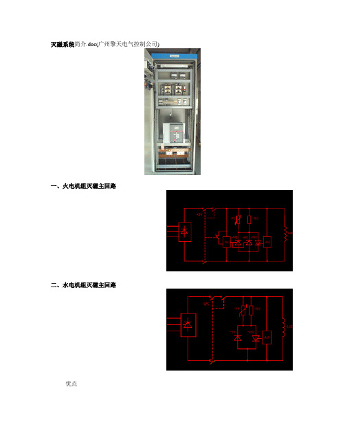
灭磁系统简介.doc(广州擎天电气控制公司)一、火电机组灭磁主回路二、水电机组灭磁主回路优点正常停机逆变灭磁,事故停机跳灭磁开关将能量转移到灭磁电阻进行灭磁正反向过压保护采用可控硅跨接器,整定方式简单.反向两并,增加可靠性智能的保护动作计数器可允许机组异步运行采用独特的熄灭线技术,转子出现瞬间过压保护动作时,可由用户选择停机或不停机处理方式三、灭磁开关自并励励磁系统仍应在直流側装备灭磁开关(尤其是采用ZnO非线性电阻灭磁),以确保在任何需要灭磁的工况下(包括空载误强励),保证快速可靠灭磁。
国产灭磁开关存在缺陷:机构误动或拒动、工艺落后、大电流开断能力不足、小电流不能可靠断弧等。
我公司一般采用进口ABB公司F1S或F4S灭磁开关,与国产开关相比,虽然价格较贵,但可靠性高、操作简便、易于维护。
F1S或F4S灭磁开关的优点:1、分合闸同步误差2、双跳闸线圈3、自动防跳功能、操作回路简单4、分合闸功率小5、辅助接点可任意设定四、ZnO灭磁应采取的措施1、ZnO参数的选择单片能容——标称15KJ,使用10KJ总能量——按最严重工况残压——转子绝缘能力,灭磁开关弧压U10mA电压——荷电率2、均能组合3、切除脉冲左图为磁场断路器分断时的灭磁回路原理图。
作用在氧化锌上的电压:UF=UW-UZ,由图可知磁场能量转移的必要条件是,作用于非线性电阻上的电压大于其残压UR,即UF>UR,右图为串联交流电源的灭磁回路原理图。
4、串联特制的快速熔断器四、SiC与ZnO对比在国内,采用ZnO非线性电阻灭磁十分普及,也较为成功。
国外则较多地采用SiC非线性电阻灭磁。
我们认为,这两种电阻各有优缺点,分析对比见下表所示:五、冗余灭磁方式近年来,国内有单位提出了冗余灭磁方式,即在转子回路串联两个磁场断路器,互为备用,以此实现冗余。
应当指出,这种方式仅仅是为了防止灭磁开关分闸失败而采取的一种防范措施,增加了主回路和控制回路的复杂性,降低了主回路的可靠性,得不偿失。
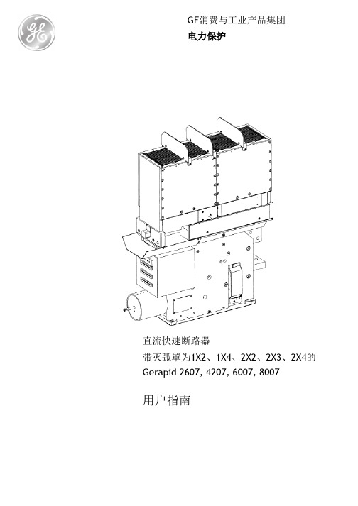
GE消费与工业产品集团电力保护直流快速断路器带灭弧罩为1X2、1X4、2X2、2X3、2X4的Gerapid 2607, 4207, 6007, 8007用户指南索引1. 警告和安全规范 (3)1.1 警告 (3)1.2 安全规范 (4)1.2.1 防止部件坠落 (4)1.2.2失压脱扣器维护 (4)2. 一般使用条件 (4)2.1 运输 (4)2.2 安装 (5)2.2.1 工作环境 (5)2.2.2 安装和接口 (5)2.3 使用 (5)2.3.1 供电和载荷 (5)2.3.2 调整OCT (5)3. 技术信息 (6)3.1 介绍 (6)3.2 零部件和附件 (6)3.2.1 触头系统 (6)3.2.3机构 (7)3.2.4 过电流脱扣装置(编码:7) (7)3.2.5 电动脱扣装置(编码:12) (8)3.2.6 辅助脱扣装置(编码:11) (8)3.2.7 强制脱扣器(编码:13) (8)3.3 技术参数表。
(12)4. 电路。
(14)4.1 控制布局。
(14)4.3 电气图 (16)4.3.1 接线编码系统。
(16)4.3.2 电压转换器。
(17)4.3.3 带外部电容器组的ED线圈。
(18)4.3.4NEKO控制装置。
(18)4.3.4NEKO控制装置。
(19)4.3.5 SU控制装置。
(20)4.3.6 分励脱扣器控制装置。
(21)4.3.7 失压脱扣器控制装置。
(22)4.3.8 指示器。
(23)4.3.9 辅助开关。
(24)4.3.10 SEL测量系统。
.......................................... 25 5. 尺寸和安全距离 (26)5.1 安全距离。
单位为毫米(英寸)。
(27)5.2 外型尺寸。
(28)5.2.1 带灭弧罩1x_的Gerapid 2607、4207、6007。
285.2.2 带灭弧罩2x_的Gerapid 2607、4207、6007295.2.3 带灭弧罩1x_的Gerapid 8007。
灭磁开关的作用是:一、发电机事故情况下利用跳灭磁开关迅速灭磁;二、在检修的时候断
开灭磁开关,形成明显的断开点。
一般停机后是不用断开灭磁开关的,因为正常停机是靠自动励磁调节器改变可控硅的触发角进行逆变灭磁。
灭磁开关也称磁场断路器,是发电机励磁回路的断路器。
一般有两对大容量的主触头(常开),合上接通发电机励磁回路。
还有一对容量相对较小的辅助触头(常闭),当需要停机或发电机故障时,灭磁开关断开,该常闭辅助触头接通,把励磁回路一时无法消除的能量快速通过
非线性电阻等元件消耗掉,达到快速灭磁的目的。
灭磁开关是在发电机停机时防止发电机过电压用的,发电机停机断开发电机出口开关时,由于原先还带有一些负荷,此时转子还供有比空载励是流还大的工作电流,当开关断开时所有的励磁电流及由于外界负荷的断开引起的汽轮机转速的升高,这两部分全部都用来建立电压,使发电机的电压高于额定电压,当不投入灭磁开关时发电机将出现过电压,使绕组发生电击穿。
说白了就是防发电机过电压保护用的。
灭磁屏:是用于装灭磁开关、灭磁电阻的柜子。
磁场变阻器:是用来调节励磁电流用的,也就是说直流电路想降低流过的电流的话可以串联一个电阻进去,磁场变阻器就是这个用用。
灭磁开关是一个两位两通开关,正常运行时使发电机与直流励磁回路相通,停机时发电机转子绕组与灭磁电阻相通进行放电。
磁场变阻器呢是串联在直流励磁回路里边的。
、灭磁开关合不上故障分析:1)合闸电源消失或合闸电路故障。
2)合闸后分闸电路接通,分闸电路故障或运行切换开关在“停止/试验”位置。
3)合闸继电器工作不正常。
4)合闸电压过低或过高。
5)灭磁开关传动机构故障。
处理方法:a)检查合闸回路保险、按钮、合闸继电器等元气件工作是否正常。
b)把切换开关切到“运行”位置。
c)重新调整合闸电源电压至其额定工作电压。
d)检查并调整操作机构或更换合闸手柄。
2、合闸线圈烧毁故障分析:1)操作机构故障或调整不当,致使线圈通电时间过长。
2)连续频繁操作次数过多。
3)线圈严重受潮、腐蚀或机械损伤,造成匝间短路。
4)灭磁开关辅助触点上的接线错误,致使线圈通电时间过长。
处理方法:a)检查并调整操作机构及延时元件的时间,回路辅助接点的动作是否正常。
b)更改接线c)更换损坏的线圈3、波形不正常故障分析:1)单元箱后面脉冲线插头没有插好2)脉冲连接线内部线路焊接不牢3)脉冲板上的脉冲线未接紧或接错4)单元箱上或脉冲板上24V 电源线接错5)可控硅坏6)同步电压缺相7)CPU 板有问题,如LM308 等芯片问题处理方法:a)将单元箱后面脉冲线插头插好b)将脉冲连接线内部线路焊接牢靠c)将脉冲板上的脉冲线接紧或核对线路,确保接线正确d)更改单元箱上或脉冲板上24V 电源线,确保接线正确e)更换可控硅f)检查试验变压器,同步变压器的电压是否正常,接线是否松动g)维修更换相应的芯片或更换CPU 板4、送上实验电源就有励磁电压显示故障分析:1)阳极三相电源或同步电压相序接反2)实验电阻未接入3)单元箱内部采样电路板故障处理方法:a)检测阳极三相电源及实验变压器、同步变压器的相序。
b)查看实验电阻的接线是否松动或错接、漏接。
c)维修电路板5、A、B 机同时在线故障分析:1)单元箱后ZX1 与ZX2 两线接反或是端子未插紧2)单元箱内部电路板故障处理方法:a)更改错误的接线,将接线接线端子插紧b)维修电路板6、采集不到备机移相故障分析:1)两个单元箱后UK1 与UK2 的线接错或端子未插紧2)单元箱内部电路板故障处理方法:a)更改接线或将接线端子插紧b)维修电路板今天本文介绍的是一款采用CD2-G型的灭磁控制电路。
灭磁开关工作原理灭磁开关是一种常见的电子设备,主要用于控制电路中的磁场。
它的工作原理是基于磁场的感应和调节。
在本篇文章中,我将详细探讨灭磁开关的工作原理,并深入介绍它的组成部分和应用领域。
一、灭磁开关的定义和功能灭磁开关是一种可控制电磁设备磁场的开关。
它通常由一对线圈和磁路控制器组成。
当通电时,线圈会产生磁场,进而影响磁路控制器的状态,从而控制磁场的产生和消失。
灭磁开关的主要功能是在需要灭磁的时候,有效地抑制或削弱磁场的强度。
二、灭磁开关的工作原理灭磁开关的工作原理基于磁场的感应和调节。
具体而言,工作原理如下:1. 通过电流激活线圈当通电时,线圈中通过电流,从而产生磁场。
这个磁场可以是永久磁体,也可以是通过电磁感应产生的临时磁场。
2. 影响磁路控制器的状态磁路控制器通常由磁铁和电磁线圈组成。
当线圈通电时,磁场会影响磁铁的位置或磁路的状态。
根据设计,磁铁的位置或磁路的状态将决定磁场是否被激活或抑制。
3. 调节磁场的产生和消失根据磁铁位置或磁路状态的变化,灭磁开关可以控制磁场的产生和消失。
当磁铁处于特定位置或磁路处于特定状态时,磁场将被激活或增强。
而当磁铁位置或磁路状态发生变化时,磁场将被抑制或减弱。
通过这种方式,灭磁开关可以有效地控制电磁设备的磁场强度。
三、灭磁开关的组成部分灭磁开关通常由以下几个组成部分构成:1. 线圈线圈是灭磁开关的核心部分,它通过通电来产生磁场。
线圈的匝数和电流决定了磁场的强度和频率。
2. 磁路控制器磁路控制器通常由磁铁和电磁线圈组成。
它的作用是控制磁场的产生和消失,通过改变磁铁位置或磁路状态来实现对磁场的调节。
3. 控制电路控制电路是灭磁开关的另一个重要组成部分。
它负责控制线圈的通电和断电,从而控制磁场的产生和消失。
控制电路通常由开关、传感器和微处理器等组件构成。
四、灭磁开关的应用领域灭磁开关在很多领域有着广泛的应用,其中包括:1. 电磁兼容性(EMC)测试:灭磁开关可以用于消除测试设备产生的磁场对其他设备的干扰。
灭磁开关断路器配以相应的吸能元器件组成灭磁装置,用于大、中容量同步发电机、调相机及大容量直流发电机的励磁回路中,作为机组定子侧内部事故状态下励磁回路的灭磁保护装置,也可用来分断空载或额定负载下的励磁回路,或用作其他直流电路的承载与分断。
2.2特征2.2.1 主要性能本系列断路器参照国际标准IEC157-1及美国标准ANSI/IEEEC37.18-1980的规定且符合低压电器基本标准GB1497中的通用部分。
断路器的主电路系采用积木式组合结构,它是由两组或四组不同数量并联的常开主触头组成,根据需要还可装设一个与灭磁电阻相串联的常闭触头。
使用时,相互串联的常开触头组接在励磁电源正极至电机的励磁绕组正极之间;上下相互串联的两组常开触头分别接于励磁电源与转子励磁绕组正极与负极之间。
相对应的主、弧触头并、串联平面排列及磁吹极性示意图。
依靠两组或四组常开触头同步分断励磁回路电源的同时,在断口间建立一个足够高的电弧电压,使断路器断口弧压之和减去励磁电源电压值后足以导通ZnO非线性电阻R(对于非线性较差的SiC或线性电阻则更容易导通),以确保转子励磁电流的转换与灭磁的顺利进行。
发电机正常运行时,断路器常开触头是闭合的,常闭触头是打开的;常闭触头的断开使非线性电阻与电源隔离,以避免可控硅励磁系统300HZ换相过电压直接加于ZnO上而导致加速老化。
当机组灭磁时常闭触头先闭合、常开触头后打开,使转子励磁电流全部转移到非线性电阻放电回路中去,达到灭磁的目的。
对于采用ZnO非线性电阻灭磁,且兼作励磁电路过压保护的机组,也可将ZnO直接(或串联可控开关后)并接在电机励磁绕组的两端而不用常闭触头。
2.2.2 结构概述2.2.2.1 接触系统磁场断路器其前后两块或左、右两侧前后的四块绝缘底板上各有数个静触头,与其相对应的数个动触头则固装在绝缘方轴上, 形成两组或四组常开触头对的接触组,各接触组通过各自静触头导电线并联连接在导电板上而与外部连接。
灭磁开关有耗能型和移能型两种,前者在灭磁时将磁场储存的部分能量消耗在燃弧过程中,并通过短弧将电压限制在合适的范围内,属于非线性灭磁。
后者则通过先期闭合的常闭接点将磁场电流转移至线性灭磁电阻,或通过建立足以使非线性灭磁电阻呈现低阻特性的电压,将磁场能量转移至灭磁电阻。
它本身也具有一定的灭磁能力。
在移能型灭磁开关中目前国内最好的当属DMX系列灭磁开关,由于采用电动合闸,永磁保持,反磁跳闸,后备跳闸,永磁吹弧等先进技术,其断开大电流、小电流的能力均超出一般灭磁开关,拒动和误跳率低,耐压高,适应性广。
灭磁开关的选择与励磁系统的型式有关。
当采用机端自并激励磁系统时,建议使用移能型灭磁开关,这主要是考虑到灭磁开关应该能分断空载误强励时的励磁电流,该电流可能达到额定励磁电流的三倍,选用耗能型灭磁开关是不合适的。