火灾动力学模拟软件FDS课件幻灯片
- 格式:pdf
- 大小:5.97 MB
- 文档页数:102

contents •FDS软件概述•FDS软件安装与配置•FDS软件基本操作•FDS软件高级功能•FDS软件在特制材料中的应用•FDS软件使用技巧与注意事项目录该软件基于计算流体动力学(CFD )和火灾科学理论,用于模拟火灾的发展和烟气运动过程。
FDS广泛应用于建筑火灾安全评估、火灾研究、应急疏散演练等领域。
FDS(Fire Dynamics Simulator)是一款由美国国家标准技术研究所(NIST)开发的开源火灾模拟软件。
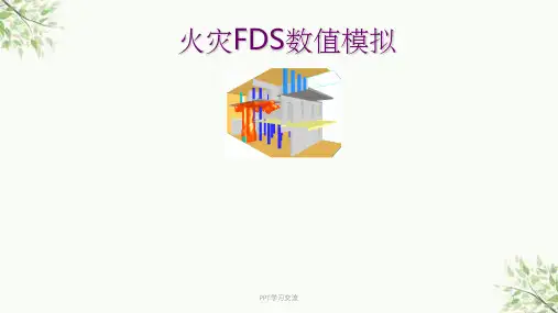
火灾场景建模FDS支持创建复杂的建筑和火灾场景,包括房间、走廊、楼梯、门窗等元素的建模。
火灾模拟FDS能够模拟火灾的发展过程,包括火势蔓延、热量传递、烟气生成和扩散等。
数据输出与分析FDS提供丰富的数据输出选项,如温度、速度、浓度等参数的时空分布,以便进行后续的数据分析和可视化。
01020304开源免费高精度模拟灵活性可扩展性获取FDS软件安装包01安装前准备02执行安装程序03安装完成后,启动FDS 软件,进入软件界面。
选择或创建一个用于存储FDS模拟文件和结果的工作目录。
根据实际需求,设置模拟的时间步长、网格大小、边界条件等参数。
导入或创建需要模拟的建筑物或场景的模型文件。
启动FDS软件设置工作目录配置模拟参数加载模型安装失败无法启动模拟结果不准确软件崩溃或无响应常见问题及解决方法界面介绍主界面菜单栏工具栏状态栏模型视图区属性栏新建创建一个新的FDS模型文件。
打开打开一个已存在的FDS模型文件。
保存保存当前FDS模型文件。
打印撤销重做剪切复制粘贴删除提供新建、打开、保存、另存为、关闭和退出等文件操作命令。
文件菜单提供撤销、重做、剪切、复制、粘贴和删除等编辑命令。
编辑菜单提供缩放、旋转、平移和视图重置等视图操作命令。
视图菜单提供层叠窗口、水平平铺和垂直平铺等窗口管理命令。
窗口菜单提供测量距离、角度和面积等工具命令。
工具菜单提供软件帮助文档和在线支持等帮助命令。
帮助菜单用户界面定制快捷键设置插件开发030201自定义功能宏命令使用宏命令创建宏命令编辑宏命令调用脚本编写与调试脚本编辑器脚本语言支持提供专门的脚本编辑器,具有语法高亮、自动补全等功能,提高编写效率。


FDS5课件2FDS5课件2:深入解析与实战应用一、引言随着我国科技水平的不断提升,数值模拟技术在火灾防治、火灾调查等领域发挥着越来越重要的作用。
FDS5(FireDynamicsSimulatorversion5)作为一款优秀的火灾动力学模拟软件,凭借其强大的功能和精确的模拟效果,得到了广泛的应用。
本文将针对FDS5课件2进行深入解析,并结合实际案例,探讨FDS5在火灾防治和火灾调查中的实战应用。
二、FDS5课件2内容解析1.FDS5基本原理FDS5是一款基于计算流体力学(CFD)的火灾动力学模拟软件,通过数值求解Navier-Stokes方程、连续性方程、能量方程等基本方程,对火灾过程中的温度、速度、压力等参数进行模拟。
FDS5课件2详细介绍了FDS5的基本原理,包括数值离散方法、边界条件设置、求解器算法等内容,为用户使用FDS5提供了理论基础。
2.FDS5功能特点FDS5课件2对FDS5的功能特点进行了详细阐述,包括:(1)多物理场耦合:FDS5能够模拟火灾过程中涉及的热传导、对流、辐射、化学反应等多物理场耦合现象。
(2)大规模并行计算:FDS5支持大规模并行计算,可充分利用高性能计算资源,提高模拟效率。
(3)丰富的模型库:FDS5提供了丰富的模型库,包括燃烧模型、热解模型、湍流模型等,用户可根据实际需求选择合适的模型。
(4)用户自定义模型:FDS5允许用户根据实际需求自定义模型,提高了软件的灵活性和适用性。
3.FDS5应用领域FDS5课件2介绍了FDS5在火灾防治、火灾调查、消防安全评估、火灾风险评估等领域的应用。
通过实际案例,展示了FDS5在解决实际问题中的优势。
三、FDS5实战应用案例分析1.火灾调查案例某高层建筑发生火灾,火灾原因不明。
利用FDS5对火灾过程进行模拟,分析火势蔓延规律,为火灾调查提供依据。
通过模拟结果,发现火灾起火点位于建筑一层,起火原因为电气故障。
根据模拟结果,调查人员有针对性地开展了调查工作,最终确认了火灾原因。
火灾动态模拟器FDS软件介绍摘要:FDS(Fire Dynamics Simulator)作为研究火灾中烟气传播规律以及火灾预防研究的开源代码,在科学研究和工程实践中得到日益广泛的应用,本文简要介绍了该软件的特点、安装平台、编译、使用方法以及注意事项,在文章末尾给出了几个典型的应用实例。
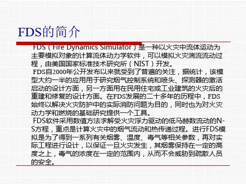
1.简介FDS(Fire Dynamics Simulator)是美国国家标准研究所(NIST:National Institute of Standards and Technology)建筑火灾研究实验室(Building and Fire Research Laboratory)开发的模拟火灾中流体运动的计算流体动力学软件。
该软件采用数值方法求解受火灾浮力驱动的低马赫数流动的NS 方程(粘性流体NavisStokes),重点计算火灾中的烟气和热传递过程。
由于FDS是开放的源码,在推广使用的同时,根据使用者反馈的信息持续不断地完善程序。
因此,在火灾科学领域得到了广泛应用。
其源码可以从/fds/下载并学习。
该软件发展到现在已有25年的历史,在九十年代中期,LES(large-eddy simulation)、NIST-LES、LES3D、 IFS(Industrial Fire Simulator)和ALOFT(ALarge Outdoor Fire Plume Trajectory)等代码统一被整理发展成为FDS,从2000年开始对外发布,2001年12月发布第二版,2002年12月发布了第三版,2004年8月发布了第四版,2005年发布了第五版,当前版本为5.2。
该程序源码包括25个独立的Fortran文件,每个都是模型相关的程序,比如:质量方程、动量方程、能量方程、压力求解、灭火洒水等。
该软件就有很大的开放性,其源码放在特定的ftp上,即使做了小的改动,也可以在ftp上发现新文件;除此之外,专门的讨论区便于使用者交流经验与发现问题。

PRODUCTSSoftware for Architecture, Engineering and Construction CYPE > in English > | Home |CYPE |New features |Products |Versions |Downloads |F.A.Q. | ContactCYPE > english > products > fds > related programsDynamic fire simulation using the Fire Dynamics Simulator (FDS)CYPECAD MEP is a program for the design of the envelope, distributionand services of the building using an integrated 3D model with thevarious elements of the building (dwellings, offices, hospitals, teachingcentres, shops, residential, etc.). It is composed of several modules ortabs, depending on the different types of installations that can bedesigned.The Dynamic fire simulation module, implemented within the Fire(FDS) tab of CYPECAD MEP, is the result of an investigation projectfinanced by the Centro para el Desarrollo Tecnológico Industrial(CDTI), and co‑financed by the European Regional DevelopmentFund (ERDF).This module of CYPECAD MEP carries out dynamic simulations of theevolution of fires in buildings using two external tools (alreadyinstalled in the program): the FDS (Fire Dynamics Simulator)analysis motor and the graphics viewer, SmokeView (SMV), bothdeveloped by the NIST (National Institute of Standards andTechnology, USA). These tools do not have a graphical dataintroduction interface or a useful and easy to use analyticalexpression of the results, and so, other tools are required for theiruse.CYPE’s Dynamic fire simulation module uses the graphical interfaceof the CYPECAD MEP program to provide the FDS motor andSmokeView viewer with the correct and required data (without theuser having to intervene in this communication). It offers a highlyuseful analysis of the results, obtained from an exhaustiveinterpretation of the results calculated by the FDS motor, and all this,without the need of a highly qualified expert in the use of the FDSmotor or fire evolution in buildings.INDEXIntroductionOperating the Dynamic fire simulation moduleActivating the analysis and required data for the dynamic simulationIntroduction of the specific data for the dynamic simulationFire load introductionFire scenario definitionAnalysis carried outCreation of the model for FDSManaging the FDS analysisResults obtainedResults within the CYPE programResults in SmokeViewRecommended hardware and softwareMultiprocessors64 bit operating systemsRelated programsIntroductionCYPE Ingenieros has carried out a project, financed by theCentro para el Desarrollo Tecnológico Industrial (CDTI), andco-financed by the European Regional Development Fund(ERDF), to implement the Dynamic fire simulation module within the CYPECAD MEP program.The Dynamic fire simulation module carries out dynamic simulations of fire evolution in buildings. To do so, it uses two external tools (installed within the CYPE program):Analysis motor For the analysis motor, the program uses the computational fluid dynamics model known as FDS (Fire Dynamics Simulator), developed by the NIST (National Institute of Standards and Technology, USA).3D viewer For the 3D graphics viewer of the evolution of the fire,SmokeView (SMV) is used, also developed by NIST.Neither tool has a graphical data introduction interface, and so the data must be introduced using text files organised in a specific way. On the other hand, the FDS motor generates,within its analysis process, a large amount of information on the fire simulation which has been undertaken. The analysis of this information is highly complex and laborious, and requires vast experience on behalf of the user to be able to express it in a useful manner.CYPE’s Dynamic fire simulationmodule uses the graphical interface of its CYPECAD MEP software to provide the FDSmotor with the correct and required data, and the SmokeViewviewer with the necessary results for a 3D animation of theresults to be obtained. All this, without the user having to intervene. CYPE’s program also analyses and interprets theresults which have been calculated by the FDS motor andgenerates control points which appear on the plan view of the Fire (FDS) tab of the CYPECAD MEP program, where the usercan obtain reports containing time graphs of the evolution of the variables monitored in the simulation.The Dynamic fire simulation module allows the user to locatethe seat of the fire at any point in the building to validate the behaviour of the smoke of the fire and check the viability of the evacuation. It can also be used for existing buildings, allowing the user to verify if the design of the building can be improved even if it already fulfils the requirements of the corresponding code.There are many factors which influence the safety of the building in case of a fire. Amongst them is the concentration and temperature of the smoke, as high levels can hinder the correct evacuation, risk the integrity of the occupants, and even aid in the structural collapse of the building. The width of the corridors, the quality of the materials and fire protection installation are some of the parameters this software takes into account, and are linked to all the CYPECAD MEP programs developed by CYPE. This allows the user to check and visualise the design alongside the corresponding design code.There is currently no other similar technology, and so the program can be of great use to Fire fighters and engineers responsible for the design of fire suppression systems and temperature control and smoke evacuation systems.More detailed information on the data introduction and the results provided by CYPE’s Dynamic fire simulation module can be found in the following sections.Operating the Dynamic fire simulation moduleActivating the analysis and required data for the dynamic simulationThe analysis of the simulation is carried out within the Fire (FDS) tab of the CYPECAD MEPprogram. Within the FDS menu of this tab, all the options required to define the simulation can be found (except the Fire loads option which can be found in the Installation menu within the same tab). These options are usually defined before the analysis. Nonetheless, the simulation can be initiated at any moment using the Analyse fire simulation option within the FDS menu (even if no other parameters have been defined) and the program will emit a warning indicating there is data missing: definition of fire scenarios, selection of building precincts to be included in the simulation,definition of fire loads and selection of the fire initiation element.Additionally, to analyse the dynamic simulation of the building, the construction elements of thebuilding must be introduced, as well as defining its precincts and, if required, fire installation protection elements such as automatic sprinklers, fire or smoke detectors are also to be introduced and are processed as such in the FDS model. If the evacuation paths are also defined, the program monitors the evolution of the smoke along the evacuation paths, which provides valuable information on the evolution of the temperature and smoke at places crossed by those paths.Introduction of the specific data for the dynamic simulationFire load introductionTo define the scene of the simulation correctly, the combustible elements occupying or furnishing the precincts where the fire will develop or can extend to, have to be introduced in the model, as these will be the main fire loads which feed and determine how the fire will evolve.For this, the program includes a tool to introduce the combustible solids (Installation > Fire loads), with an associated common combustible materials library, containing the required data for the FDS model, such as combustion and vaporisation enthalpies,pyrolysis, heat release rates, loss of mass, etc.The construction elements making up the geometric model of the building are characterised automatically in the FDS model, achieving a simple, easy and intuitive introduction of the combustible and non-combustible elements in the simulation.Fire scenario definitionTo create the fire models which the FDS motor will analyse, a tool can be used which manages the different fire scenarios in the building, so that, in a single file for the whole building, different fire scenarios and their corresponding results from the dynamic simulation can be managed. This way, data introduction is greatly simplified and the elaboration of new fire scenarios and the analysis of each of their results can be carried out in a more agile manner. This also allows the user to compare and analyse different fire scenarios within the building, to obtain a better understanding of the positive aspects and errors of the design,and so reaching the most optimum configuration for temperature control and smoke evacuation.These fire scenarios are created using the Fire scenario option within the FDS menu . Theprogram allows the user to create, copy and edit the different fire scenarios of the building, and select any of them and work on their associated data, which includes:Selection of the building precincts This selection is carried out using the following menu:Selection of precincts to include in the simulation ,within the FDS menu. The number of precincts included in the simulation will determine the size of the model which is launched in the analysis, and hence, the time required to analyse it.Selection of the elements initiating the fire The selection of the load or fire loads which begin to burn at the start of the simulation is carried out using the following option: Selection of fire initiation elements ,within the FDS menu.Status of the openings The status (whether open or closed) of the openings present in the building, such as doors or windows, will determine the air flow of the fire and, therefore, its evolution. To open or close an opening, use the following option: Behaviour of openings in the simulation , withinthe FDS menu.Apart from this information, the FDS model that is generated for each fire scenario includes control logics which allow for certain changes to be carried out on the model during the simulation.So, windows or skylights which start off as closed in thesimulation , can break at a particular moment of the simulationif the necessary pressure and temperature conditions arise, and so the ventilation conditions can vary during the simulation. Additionally, if sprinklers or heat or smoke detectors have beendefined, these are linked with a logic which simulates the fire alarm signal of the building, with some delay, which allows to act upon other elements of the building, such as closing of magnetic retention firebreak doors or the opening of smoke vents for smoke evacuation at roof level. Thevideo displays an example of the simulation carried out by the program . Here, it can be seen how at a particular moment, the smoke vents on the roofs open (with the consequent reduction of theaccumulated smoke layer inside the warehouse) and the sprinklers of the fire protection installation come into action.Analysis carried outCreation of the model for FDSHaving introduced all the necessary data correctly, and using the Analyse fire simulation option from the FDS menu, any of the defined fire scenarios can be analysed. Upon executing this option, the General data configuration window will open, together with the list of fire scenarios defined for the building.Within this window, the only thing left to do is choose thescenario to simulate and define two essential parameters for theanalysis of the dynamic simulation: the cell size of the mesh ofthe FDS model and the duration of the simulation.The cell size for the discretisation defines the precision of themesh of the building FDS model and determines the number ofcells the analysis must manage, which is directly proportional tothe time taken to analyse the simulation and the memory spacerequired to carry it out.15, 20 or 25 cm cell size values are considered to be sufficiently precise to analyse the behaviour of the smoke of the fire in large volumes. Nonetheless, in early phases of the behavioural study of the building on fire, faster simulations can be undertaken by introducing higher mesh values. Sizes smaller than 15 cm imply a very dense analysis and are only required for fire and smoke analysis studies in reduced volumes.The duration of the simulation determines the real time of thefire evolution to analyse and begins with the ignition of the fireloads established as the initiation elements. The FDS analysismotor is valid to analyse the behaviour of the smoke and fire, andso is useful to study its early phases, including the evacuation ofthe occupants of the building. However, it is not valid to simulatethe possible structural collapse of the building, and so simulationswhich last longer than 30 minutes are not recommended ornecessary.A feature worth highlighting ofthe program, compared toother modelling tools for theFDS, is the completeindependence of the buildingmodel with respect to the cellsize and mesh of the FDS model. In other words, the 3D model ofthe building, which is managed and edited in the program(shared with the other CYPECAD MEP analysis models)corresponds to the model with the real dimensions of eachelement present within it; and the model that is exported to theFDS motor (which is created automatically when the dynamicsimulation of the building is initiated) is specific for the scenario selected by the user (with the precinct subgroup it contains and the chosen discretisation), and is optimised for the number of processors used in the analysis and for the configuration of construction and combustible elements present in the simulation.This manner of working allows the user to forget many of the limitations of the FDS model, such as the alignment of the meshes or having to define obstacles (OBST entities of the model), as the program builds the model adjusting itself to the chosen cell size, modifying the thermal properties of the materials or objects, in such a way that the resultant model can be analysed without any problems for the FDS motor, in a minimum amount of time, and respecting the thermal behaviour of the real model. This presents an obvious advantage for the study of the dynamic behaviour of the fire within the building: it allows for different versions of the model to be simulated, with more or less details (i.e. more or less complex to analyse) by simply varying the cell size.Managing the FDS analysisOnce the model for the FDS has been created, a window willopen automatically which manages the dynamic analysis. Theprogram uses the optimum FDS motor in the computer at which itis executed (32 or 64 bit and with processors in one or severalCPU s). The last version of the Dynamic fire simulation programalways includes the last validated version of the FDS published bythe NIST.This manager window of the FDS analysis is opened as an independent process, which allows the user to continue working on the model, defining other fire scenarios or buildings, whilst the analysis of the simulation is taking place.Within this window, the user can view the duration of thesimulation analysis, and the estimated remaining time; the realduration of the achieved simulation; buttons to view thegenerated *.fds file and, launched for the simulation, the outputfile, *.out, which is generated by the FDS motor; and the buttonto activate SmokeView with the data of the simulation oncourse.Using SmokeView, which has been developed by the NIST and ispartner of the FDS analysis motor, the results of the simulationcan be accessed up to the analyses moment whilst the analysis isstill taking place. This allows for the evolution of the smoke withtime to be explored as well as the fire temperature, in acompletely 3D visual manner, as well as allowing the user to study the repose of the detection and alarm systems of the building or, even, the activating and working of the automatic sprinklers. From the management window of the dynamic simulation analysis, the analysis on course can also be stopped and results can be obtained as of the first instant of the simulation up to the moment reached in the analysis. It is also possible to continue with the analysis as of the moment it was stopped, allowing for it to be dealt with in different stages.Results obtainedResults within the CYPE programAfter the analysis, the FDS motor generates a vast amount ofinformation on the fire simulation that has been carried out. Theanalysis of this information is highly complex and laborious, andrequires a lot of experience on behalf of the user to be able toexpress it in a useful way. The Dynamic fire simulation modulecontains a tool which post-processes and generates the resultsof the simulation carried out by the FDS motor so it can beanalysed with the CYPE program.This tool can be activated using the Show simulation resultsoption within the FDS menu. Once activated (in jobs withcompletely analysed fire scenarios or paused at a particularmoment), control points appear on the plan view of the building.Depending on the control point at which the user places thecursor, the following information appears on screen:Activation of smoke or heat detectorsActivation of sprinklersAlong the evacuation paths, the following are displayed:The instants when dangerous temperatures areexceeded in the smoke layerWhen the smoke-free height falls below 2mBy clicking on any of thesecontrol points using the leftmouse button, reports aregenerated, which include graphsthat display how the followingfactors evolve in time during thesimulation:The temperature insprinklers or heatdetectorsThe degree of darknessin smoke detectorsThe temperatures of the cold layer and smoke layer, and the smoke free height(parameters which are required for the SCTECH design in accordance with EN 12101-5:2005) along the established evacuation paths of the building.Results in SmokeViewApart from the control points and columns generated within the FDS model, which are then post-processed to obtain results graphs in the program, upon generating the FDS model, certain control planes are added so they can be inspected in the SmokeView viewer.For each floor of the building which is analysed in the simulation, temperature distribution planes are added, as well as air velocity control planes and visibility defree planes in metres. This way, within the SmokeViw viewer, as well as the being able to represent the smoke and fire which isgenerated, the evolution of these magnitudes in horizontalplanes can also be represented per floor. Therefore, with thistool, the user can rapidly judge how the building and its smokeevacuation and temperature control systems behave.Recommended hardware and softwareThe complexity of a fire dynamics simulation of a building and themultiple factors which intervene, implies the computer at whichthe simulation is going to be analysed has more hardware andsoftware requirements than those required to operate normal programs. Emphasis is especially given to the possibility of using processors with several nuclei and the operating system of the computer where the simulation is going to be analysed.MultiprocessorsThe Dynamic fire simulation module can work with another module of CYPE, Parallel analysis with up to eight processors. This way the user can make the most of the division capacity of the analysis work of the simulation in different FDS model meshes so it can be processed in parallel and that of modern CPUs containing several nuclei, and the lengthy analysis time of the dynamic fire simulations is reduced. To be able to carry out complex simulations, it is essential CYPE’s Parallel analysis with up to eight processors module be included in the user license.64 bit operating systemsBoth the FDS analysis motor and the SmokeView results viewer work on computers with 64 bit operating systems, and so it is possible to carry out complex simulations with a high number of cells which are generated, either due to the building zone which is to be simulated, or because of the reduced size of a unit cell. Thanks to this, the RAM memory restrictions imposed on 32 bit processors (2 GB per process) are eliminated.Simulation models containing more than 2 million cells cause memory problems to arise in 32 bit operating systems. The program emits a warning of this upon generating the model, which allows the user to correct the size of the zone to simulate, or increase the unit cell size, so to create a mesh with a lower number of cells.In any case, to be able to carry out complex simulations, either due to their large size or their dense mesh, or because automatic extinguishing systems come into use in the simulation (fire extinguishing using automatic sprinklers), it is always recommended that 64 bit operating systems be used and if possible these be associated with a CPU with several nuclei and a RAM memory greater than 4 GB.Related programsCYPECADSteelMetal 3DPortal frame generatorContinuous beamsSoil retention elementsCantilever retaining wallsEmbedded retaining wallsCivil worksBox culvertsArquimedes. Create, manage and control bills of quantities, project certifications andspecificationsCYPECAD MEPAir conditioningDynamic fire simulationTop©CYPE Ingenieros, S.A. - Avda. Eusebio Sempere, 5 - 03003 ALICANTE. SpainTel. USA (+1) 202 569 8902 // UK (+44) 20 3608 1448 // Spain (+34) 965 922 550 - Fax (+34) 965 124950Home | CYPE | Products | Versions | Downloads | Contact usBulgarian | French | Italian | Portuguese | Spanish | Spanish (Mexico) | Other dealerships。