泓格I-7565H1H2高效能USBCAN转换器快速使用手册
- 格式:pdf
- 大小:692.14 KB
- 文档页数:9
User’s ManualWarrantyAll products manufactured by ICP DAS are under warranty regarding defective materials for a period of one year from the date of delivery to the original purchaser.WarningICP DAS assumes no liability for damages resulting from the use of this product. ICP DAS reserves the right to change this manual at any time without notice. The information furnished by ICP DAS is believed to be accurate and reliable. However, no responsibility is assumed by ICP DAS for its use, or for any infringements of patents or other rights of third parties resulting from its use.CopyrightCopyright 2011 by ICP DAS. All rights are reserved.TrademarkThe names used for identification only may be registered trademarks of their respective companies.Table of Contents1.Introduction (3)1.1Features (4)1.2Specifications (4)2.Hardware (6)2.1Block Diagram (7)2.2Pin Assignment of HART Port (8)2.3Terminator Resistor Settings (8)2.4Init / Normal Dip-switch (9)2.4.1Firmware Update Mode (9)2.4.2Firmware Operation Mode (11)2.5LED Indication (12)2.5.1LED function (12)2.5.2LED indication (13)2.6Cable Selection (13)3.Driver Installation (14)3.1Install I-7567 Driver by Auto (14)3.2Install I-7567 Driver by Manual (15)3.3Verify Driver Installation (18)3.4Uninstall I-7567 Driver (19)4.HART Converter Utility (21)4.1Run Utility (21)4.2Communication Settings and HART Frame Settings (21)4.2.1Communication Settings (22)4.2.2HART Frame Settings (22)4.3Search the HART device via the I-7567 (25)4.4Data logger (27)4.5Send/Receive HART Frame (27)1. IntroductionThe I-7567 is a USB to HART converter specially designed for the master device of HART protocol. It allows users to access the HART slave by using virtual COM-port and the baud rate must be set 1200bps .First installation, connecting the I-7567 to PC, PC will load the relevant device driver automatically (hot plug & play). Therefore, users can make data collection and processing of HART bus network easier and quicker by applying I-7567. The ICP DAS also provides the utility tool for users to configure the I-7567.The following is the application for the USB/HART modules:1.1 Features∙Support HART Short/Long frame∙Allow two HART masters∙Working in point-to-point or multi-drop HART mode ∙Connecting up to 16 HART modules∙Provide utility tool for module configuration∙No external power supply (powered by USB)∙Support firmware update via USB∙Provide PWR / Tx / Rx indication LED∙4KV ESD Protection∙Selectable 250Ω load resistor1.2 Specifications[ USB specs: ]∙Input port : USB (USB Type B)∙Compatibility : USB 1.1 and 2.0 standard∙Driver Supported : Windows 2000/XP/Vista/7[ HART specs: ]∙HART interface connector: 10-pin terminal-block∙HART Baud Rate : 1200bps∙Isolation Voltage : 3KVDC on the HART side[ Module specs: ]∙Dimensions : 108mm x 72mm x 35mm (H x W x D) ∙Operating temperature : -25 to 75ºC (-13 to 167ºF); ∙Storage temperature : -40 to 80ºC (-40 to 176ºF); ∙Humidity : 5 to 95%, non-condensing;∙LEDs :PWR LED for powerTx LED for HART frame from USBRx LED for HART frame from HART device[ Software Utility Tool: ]∙Easily and quickly installation∙Easily search HART devices∙Provide user-defined HART frame ∙Provide simple Data logger[ Application: ]∙Current Measuring;∙Petrochemical Industry Application; ∙Environment Monitoring;∙Tunnel Monitoring;∙Monitor system;∙Building Monitoring etc.;2. Hardware2Figure 2-1: Hardware externals of I-75672.1 Block DiagramFigure 2-2 is a block diagram illustrating the functions on the I-75672.2 Pin Assignment of HART PortFigure 2-3: Pin Assignment on I-75672.3 Terminator Resistor SettingsThe DIP Switch can provide HART network with 250 Ω (1/4 W) resistor. When it set to “On”, the resistor will connect to HART network. Otherwise, it will disconnect the resistor from HART network.Figure 2-6: Open Internal Resistor Figure 2-7: Close Internal Resistor2.4 Init / Normal Dip-switchOn the I-7567 PCB, there is a Jumper(JP1) used for firmware operation or firmware updating of the module. The following steps show how to use this dip-switch.Figure 2-7: Firmware Operation Figure 2-8: Firmware Updating 2.4.1 Firmware Update ModePlease set the Jumper(JP1) to the Firmware Updating position like Figure 2-8. Then the I-7567 will work in the “Firmware Update Mode” after the power of the module has been turned on again. In this mode, users can update the firmware of the I-7567 module via USB and the module will become a “USB Mass Storage Device” and also shows a folder like Figure 2-9 automatically.Figure 2-9: USB Mass Storage DeviceUsers just need to execute “Firmware_Update_Tool.exe” and follow the below steps to complete the firmware updating process.[1] Choose “USB” interface and “USB Disk”.[2] Click “Browser” button to choose firmware file. (like I7567_v1.00.fw)[3] Click “Firmware Update” button to start firmware updating process.The result will show in “Firmware Update” field.The Firmware_Update_Tool program can be downloaded from /pub/cd/fieldbus_cd/HART/converter/I-7567/software/tool2.4.2 Firmware Operation ModeIn operation mode, users need to set the Jumper(JP1) to the firmware operation position like Figure 2-7 and pull out the USB plug to turn power off then on again so that the I-7567 can run in the operation mode. In this mode, users can send / receive HART frame via PC USB port.2.5 LED IndicationThere are three LEDs provided to indicate to users what situation the I-7567 is in. The following is the illustration of these three LEDs and the position of these three LEDs shows as Figure 2-10.Figure 2-10: LED position of I-75672.5.1LED function(1) PWR LED :It is used to help users to check whether the I-7567 is standby. If the module is working in “firmware operation” mode, the PWR LED is always turned on. However, when the module is working in the “firmware updating” mode, the PWR LED will turn off.(2) Tx LED :It is used to show whether the I-7567 is receiving HART frame from USB. The Tx LED will flash whenever a HART frame is receiving.(3) Rx LED :It is used to show whether the I-7567 is receiving HART frame from HART Device. The Rx LED will flash whenever a HART frame is receiving.2.5.2 LED indication2.6 Cable SelectionThe HART bus is a balanced (differential) 2-wire interface running over either a Shielded Twisted Pair (STP), Un-shielded Twisted Pair (UTP), or Ribbon cable. How to decide a cable type, cable length, andterminator in the HART bus network, please refer to the following table:Note: The AWG means a standard method used to measure wire. The numbering system works backwards from what people would think, the thicker (heavier) the wire, the lower the number.LED Name Power off No Driver Firmware Updating FirmwareOperationReceivingHART Framefrom PCReceiving HART Frame from HART DevicePWR LED off flash off on on on Tx LED off flash off off flash off Rx LEDoff flash off off off flash3. Driver InstallationThis section will show how to install the I-7567 USB/HART converter device driver under Windows 2000/XP and Win7. Users can downloadthe I-7567 device driver from ICP DAS web site:ftp:///pub/cd/fieldbus_cd/hart/converter/I-7567/driver Please follow the below steps to finish I-7567 driver installation.3.1 Install I-7567 Driver by Auto[ Step - 1 ]Plug in the I-7567 to PC first and Windows will detect the new device and shows the “Found New Hardware Wizard” screen prompting you to install the driver for the detected USB Device. Please click “Cancel” button to cancel driver installation by manual like Figure 3-1.2Figure 3-1: New Hardware Wizard (1)[ Step - 2 ]Execute “ICPUsbConverter_DrvInst_v1.2.exe“ file to install driver automatically and then click “Continue Anyway” button like Figure 3-2. After driver installation process finished, it will show the screen like Figure 3-3.Figure 3-2: New Hardware Wizard (2)Figure 3-3: Install I-7567 Driver Finished3.2 Install I-7567 Driver by Manual[ Step - 1 ]Please execute “ICPUsbConverter_DrvInst_v1.2.exe“ file first to install driver files of I-7567 to system.[ Step - 2 ]Plug in the I-7567 to PC and Windows will detect the new device and shows the “Found New Hardware Wizard” screen prompting you to install the driver for the detected USB Device. Please select “No, not this time” option and click “Next” button like Figure 3-4.Figure 3-4: New Hardware Wizard (1)[ Step - 3 ]Please select “install from a list or specific location (Advanced)” option and click “Next” button like Figure 3-5.Figure 3-5: New Hardware Wizard (2)[ Step - 4 ]Please select “Search for the best driver in these locations” option and check “include this location in the search:” checkbox and click “Browser” button to assign the I-7567 driver location - C:\WINDOWS\inf\ and then click “Next” button like Figure 3-6.Figure 3-6: New Hardware Wizard (3)[ Step - 5 ]Please click “Continue Anyway” button like Figure 3-7 .Figure 3-7: New Hardware Wizard (4)[ Step - 6 ]Please click “Finish” button to complete I-7567 device driver installation like Figure 3-8.Figure 3-8: New Hardware Wizard (5)3.3 Verify Driver InstallationThis section will show how to verify whether the driver of I-7567 was properly installed. If the driver is installed successfully, then there will be a “Virtual COM Port” assigned by Windows. Please follow the below steps to check it.Click “Start” → “Settings” → “Control Panel” and then double click on the “System” icon. Once the “System Properties” screen displayed, click on ” Hardware” tab and then click on the “Device Manager” button. Double-click on Ports (COM & LPT) item. If the device driver was correctly installed, users can find the “ICPDAS I-7567 USB2HART” device listing and the “Virtual COM Port” number that Windows has assigned to the device is COM3 like Figure 3-9.Figure 3-9: Virtual COM Port Number3.4 Uninstall I-7567 DriverPlease follow the below steps to uninstall I-7567 device driver.[ Step - 1 ]Click “Start” → “Settings” → “Control Panel” and then double click on the “System” icon. Once the “System Properties” screen displayed, click on ” Hardware” tab and then click on the “Device Manager” button. Double-click on Ports (COM & LPT) item. Please find the “ICPDAS I-7567 USB2HART” device listing and click the right button on the mouse andchoose “Uninstall” item like Figure 3-10.Figure 3-10: Uninstall I-7567 Driver (1)[ Step - 2 ]Click “OK” button to complete I-7567 device driver un-installation like Figure 3-11. After that, the “ICPDAS I-7567 USB2HART” device listing willdisappear on Ports (COM & LPT) item.Figure 3-11: Uninstall I-7567 Driver (2)4. HART Converter UtilityI-7567 Utility is provided by ICP DAS to transmit / receive HART frame for HART bus communication testing easily and quickly. I-7567 Utility can be downloaded from the ICP DAS web site :/pub/cd/fieldbus_cd/hart/converter/I-7567/software/utility. The following is the main functions provided by I-7567 Utility :4.1 Run UtilityRun the “I-7567 Utility” HC_Tool.exe, and then click the “Settings” of menu to configure the parameters of communication like Figure 4-1.If users can’t run “HC_Tool.exe”, please install .NET Framework 3.5. And then run utility again.Figure 4-1: Open the “Settings” of menu4.2 Communication Settings and HART Frame SettingsPlease refer to the section 4.2.1 to set com port and the section 4.2.2 to configure the HART frame.4.2.1 Communication SettingsPlease refer to the section 3.3 to find com port number.Figure 4-2: Set Port Name4.2.2 HART Frame SettingsThe “Hart” index offers the format of short or long frame to transmit Command #0 for searching the HART device (Figure 4-3). User can refer the following Introduction to set HART frame.Auto Configure: Select Automatic or Manual to send HART frame.Frame type: Select the format of short frame or long frameMaster type: Select Primary master or Secondary masterPreambles: 5~20 bytes (0xFF)Address: Polling Address(0~15)Manufacturer ID: Manufacturer Identification CodeDevice type: Manufacturer’s Device Type CodeDevice ID: Device Identification NumberFigure 4-3: Set the format of HART frameHow to configure the HART frame via the utility? Users can modify “Auto Configure” to select Disable or Enable. If it is Enable, the utility will be used format of short frame to polling HART device(Figure 4-4).Figure 4-4: Set Auto Configure to EnableWhen “Auto Configure” is “Disable”, users must be referred “Frame type” to set the format of “Short” frame or “Long” frame. If it is “Short” frame, users only set Master type, Preambles, Address(Figure 4-5). Otherwise, users must be set about Frame type, Master type, Preambles, Manufacturer ID, Device type, Device ID(Figure 4-6).Figure 4-5: Short frame settingsFigure 4-6: Long frame settingsIf Communication and HART frame settings have set up, please click the“OK” button.4.3 Search the HART device via the I-7567If users have finished above the settings, please refer to the following steps to search the HART device via sending Command #0.Step 1: Click the “Open” button to connect com port(Figure 4-7).Figure 4-7: Click “Open” buttonIf the screen showed the error message after clicking “Open” button, please check the port number and reset Port Name.Step 2: Click the “Start” button to search HART device with HART bus(Figure 4-8).Figure 4-8: Click “Start” buttonUsers can find the related information of HART device after clicking(Figure 4-9).Figure 4-9: Find HART deviceIf the utility showed error information (Figure 4-10), users must be checked the communication of HART bus, the format of HART device frame.Figure 4-10: Search Device Failed4.4 Data loggerWhen users click “Start” button or run the SRMsg of menu, the utility will record HART frame from PC or HART device. But close the utility, the information of Data logger will disappear.4.5 Send/Receive HART FrameUsers can send and receive HART command directly by the following window.Step 1: Set HART command to Send Data, and then click the “Send”button.Step 2: The response data of HART device will be showed the “Receive Data”. When the “Receive Data” is showed empty,please check the format of HART frame from the “Send Data”or HART communication.。
I-7530 RS-232/CAN 转换器使用手册(Version 2.3, Oct/2009)目录1. 简介 (1)1.1 特性 (2)1.2 规格 (3)2. 硬件 (5)2.1 硬件方块图 (5)2.2 脚位说明 (6)2.3 硬件连接 (8)2.4 终端电阻设定 (9)2.5 初始/正常(Init/Normal) 设定开关 (10)2.6 LED指示灯号 (11)2.7 线路选择 (13)3. 工具软件 (14)3.1 如何设定模块参数 (15)3.2 如何设定接受码(ACC)与接受屏蔽(ACM) (19)3.3 在CAN网络上测试I-7530(仅适用于正常模式) (20)3.4 配对联机(Pair Connection)模式说明 (22)4. 命令表 (28)4.1 tIIILDD...[CHK]<CR> (30)4.2 TIIIL[CHK]<CR> (31)4.3 eIIIIIIIILDD...[CHK]<CR> (32)4.4 EIIIIIIIIL[CHK]<CR> (33)4.5 S[CHK]<CR> (34)4.6 C[CHK]<CR> (36)4.7 P0BBDSPAE[CHK]<CR> (37)4.8 P1B [CHK]<CR> (39)4.9 RA[CHK]<CR> (40)4.10 一般命令错误码 (41)5. 故障排除: (42)1. 简介CAN(Controller Area Network;控制器局域网络)是一种串行式总线控制协议,适合用于建构智能型工业设备网络及自动控制系统。
一些可程序的控制器,如PC ,I-8000,WinPAC-8000嵌入式控制器可以透过使用I-7530来控制CAN的网络。
因此,这些控制器可以透过I-7530控制或监控CAN设备。
此外,我们扩展了I-7530一些额外的特殊应用功能。
tGW-700系列中文使用手册(版本1.2, 2011年7月)目录检查配件 (1)更多信息 (1)1. 产品介绍 (2)1.1 何谓E THERNET 解决方案 (3)1.2 何谓W EB S ERVER技术 (4)2.硬件信息 (5)2.1 规格 (5)2.2 特色 (6)2.3 选型指南 (6)2.4 T GW-700配置图 (7)2.5 机构图 (9)2.6 脚位定义 (11)2.6.1 tGW-712 脚位定义 (11)2.6.2 tGW-722 脚位定义 (12)2.6.3 tGW-732 脚位定义 (13)2.6.4 tGW-715 脚位定义 (14)2.6.5 tGW-725 脚位定义 (15)2.6.6 tGW-735 脚位定义 (16)2.6.7 tGW-718 脚位定义 (17)2.6.8 tGW-724 脚位定义 (18)2.6.9 tGW-734 脚位定义 (19)2.7 RS-232/422/485接线 (20)2.7.1 RS-232 接线 (20)2.7.2 RS-422 接线 (21)2.7.3 RS-485 接线 (21)3. 启动TGW-700模块 (22)步骤1:连接电源和计算机主机 (22)步骤2:安装M ODBUS U TILITY及E S EARCH U TILITY 到您的计算机 (23)步骤3:以太网络配置设定 (24)步骤4:测试 T GW-700 (25)4. 配置网页 (29)4.1 登入T GW-700网页服务器 (29)4.2 H OME 首页 (31)4.3 N ETWORK S ETTING (32)4.3.1 Network and Miscellaneous Settings (32)4.3.2 IP Address Selection (32)4.3.3 General Configuration Settings (35)4.3.4 Restore Factory Defaults (36)4.4 P ORT1设定 (37)4.4.1 Port1 Settings (37)4.4.2 Port Settings (37)4.4.3 Pair-Connection Settings (38)4.5C HANGE P ASSWORD (39)4.6L OGOUT (39)5. TGW-700 应用 (40)5.1 M ODBUS G ATEWAY (40)5.2 P AIR-C ONNECTION应用 (41)步骤1:连接至网络、电源和计算机主机 (42)步骤2:以太网络配置设定 (43)步骤3:在 T GW-700#1网页服务器配置P AIR-C ONNECTION (43)步骤4:在 T GW-700#2网页服务器配置P AIR-C ONNECTION (45)步骤5:测试P AIR-C ONNECTION 功能 (45)附录: 相关名词 (48)1. ARP(A DDRESS R ESOLUTION P ROTOCOL) (48)2. C LIENTS/S ERVERS (48)3. E THERNET (48)4. F IRMWARE (48)5. G ATEWAY (49)6. ICMP(I NTERNET C ONTROL M ESSAGES P ROTOCOL) (49)7. I NTERNET (49)8. IP(I NTERNET P ROTOCOL) ADDRESS (49)9. MAC(M EDIA A CCESS C ONTROL) ADDRESS (49)10. P ACKET (50)11. P ING (50)12. RARP(R EVERSE A DDRESS R ESOLUTION P ROTOCOL) (50)13. S OCKET (50)14. S UBNET M ASK (50)15. TCP(T RANSMISSION C ONTROL P ROTOCOL) (51)16. TCP/IP (51)17. UDP(U SER D ATAGRAM P ROTOCOL) (51)附录: FAQ (52)1. 使用IE浏览器进入T GW-700网页服务器时,如IE浏览器画面显示为空白,请执行下列步骤。

PCI-P8R8/P16R16/P16C16/P16POR16用户手册承诺郑重承诺:凡泓格科技股份有限公司产品从购买即日起一年内无任何材料性缺损。
免责声明凡使用本系列产品除产品质量所造成的损害,泓格科技股份有限公司不承担任何法律责任。
泓格科技股份有限公司有义务提供本系列产品可靠而详尽资料,但保留修订权利,且不承担使用者非法利用资料对第三方所造成侵害构成的法律责任。
版权版权所有 © 1999泓格科技股份有限公司,保留所有权力。
商标手册中所涉及所有公司商标,商标名称及产品名称分别属于该商标或名称的拥有者所有。
许可用户可以使用、修改和备份单片机上的软件部份,但无权复制,转移或发布该软件的全部或部份拷贝。
目录1绪论 (1)1.1. 特点和应用 (2)1.1.1.特点 (2)1.1.2.应用 (2)1.2. 结构图 (3)1.3. 规格 (4)1.4. 硬件结构 (6)1.4.1.住流拆封 (6)1.4.2.板卡布局 (7)1.4.3.跳线设置 (9)1.5. 引脚分配 (10)2硬件应用 (13)2.1 继电器输出 (13)2.2 集电极输出 (14)2.3 P HOTO M OS 继电器输出 (15)2.4 隔离输入 (16)3软件安装向导 (18)3.1 W INDOWS 95/98/2000/XP平台安装 (18)3.2 DOS平台安装 (26)3.3 WINDOWS95/98/NT/2000/XP平台安装 (26)4I/O控制寄存器 (27)4.1 调用功能P16R16.DLL (32)4.2 P16R16.H (32)4.3 PCI_F LOAT S UB2 (33)4.4 PCI_S HORT S UB2 (34)4.5 PCI_G ET D LL V ERSION (34)4.6 PCI_D RIVERLNIT (35)4.7 PCI_D RIVER C LOSE (37)4.8 PCI_G ET D RIVER V ERSION (37)4.9 PCI_G ET C ONGFIG A DDRESS S PACE (38)4.10 P16R16_DO (39)4.11 P16R16_DI (39)4.12 8R8_DO (43)4.13 P8R8_DI (43)1 绪论型号数字量隔离输入输出类型通道继电器输出PCI-P8R8 8通道8PCI-P16R16 16 通道 16 通道继电器输出通道源OC门输出PCI-P16C16 16 通道16通道 PhotoMos继电器输出PCI-P16POR16 16 通道16•PCI-P8R8 / PCI-P16R16PCI-P16R16和PCI-P8R8适用于工控机上或于之相容的PC机。
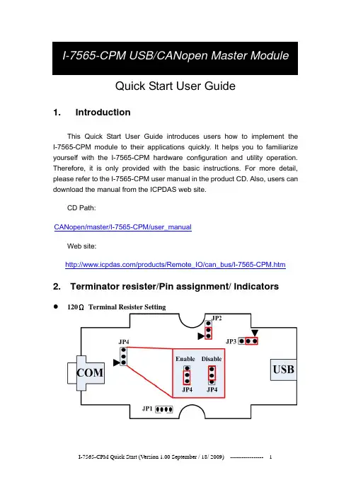
Quick Start User GuideCAN 1. IntroductionThis Quick Start User Guide introduces users how to implement the I-7565-CPM module to their applications quickly. It helps you to familiarize yourself with the I-7565-CPM hardware configuration and utility operation. Therefore, it is only provided with the basic instructions. For more detail, please refer to the I-7565-CPM user manual in the product CD. Also, users can download the manual from the ICPDAS web site.CD Path: open/master/I-7565-CPM/user_manualWeb site: /products/Remote_IO/can_bus/I-7565-CPM.htm2. Terminator resister/Pin assignment/ Indicators z 120ΩTerminal Resister Settingz Pin assignment(1) 9-pin D-Sub male connector(2)IndicatorsACT LEDIf the I-7565-CPM is running normally, the ACT LED will be turned on always. If this LED is off, please check the power supply or contact to your distributor.Tx/Rx LEDIt is applied to check the status of the transmission and reception of CAN messages. If I-7565-CPM is transmitting or receiving a CAN message, the Tx/Rx LED will blink. If I-7565-CPM’s loading is heavy, the Tx/Rx LED will be always turned on.ERR LEDThe ERR LED indicates the error status of the CAN physical layer. It also indicates the errors due to the software/hardware message buffer overflow.PWR LEDThe power consumption of I-7565-CPM is 3W. If the power is given normally, the PWR LED and ACT LED will be turned on always. If this LED is off, please check the power supply or contact to your distributor.3. Install I-7565-CPM UtilityWe provide the I-7565-CPM Utility. There are several functions supported by the utility. They are shown as follows.1.Configure NMT mode, SYNC COBID, SYNC transmission time,Guard time, Life time, EMCY COBID, PDO polling time and SDOpolling time.2.Install the PDO or SDO object so that users can use it by using theutility.3.Remove CANopen node, PDO object or SDO object.4.Support TxPDO, RxPDO, TxSDO, and RxSDO.5. Record EMCY messages.Step 1: Download the I_7565_CPM Utility setup file from the web site/download/can/index.htm or the CD in the productbox.The path is “/Napdos/iCAN/CANopen_MASTER/I-7565-CPM”.Step 2: Execute the I_7565_CPM SETUP.exe file to install the CANopen master utility on your PC.Step 3: After finishing the installation of the I-7565-CPM Utility, users can find the I-7565-CPM Utility, the NMT_ Demo, the PDO_Demo, theSDO_Demo, and the DO_DI_AO_AI_Demo, as follows.4.Driver installation of I-7565-CPMWhen finishing the I-7565-CPM utility installation. The USB driver of I-7565-CPM can be found at the C:\ICPDAS\CAN_Gateway\I_7565_CPM\USB Driver\i-756x driverinstaller.exe, that will be used in 98/NT/Me/2000/XP windows environments. Then the installation process will copy the related material to the indicated directory and register the driver on your computer. The driver target directory is below for the different systems.Windows NT/2000 – WINNT\SYSTEM32\DRIVERSWindows 98/Me/XP – WINDOWS\SYSTEM32\DRIVERSing I-7565-CPM Utility5.1 Example for the demo applicationThe I-7565-CPM utility provides some useful and easy-to-use functions. Before using it, users need to prepare a computer, an I-7565-CPM, a CAN-8123and an I-8077, as follows. (CAN-8123+I-8077 is a DI/DO CANopen slave)Afterwards, run the Utility, I-7565-CPM.exe. The application interface will be shown as follows. Click the “Select COM” item to select the computer COM port, CAN bus baud rate and “Add Node Timeout”. The “Add Node Timeout” is the time interval between each two commands in adding node procedure. Then click X button to close the dialog. Click the “Scan” button in the main window to scan the I-7565-CPM. If there is an I-7565-CPM connected with users’ computer, the CANopen slaves which are in the same CANopen network with I-7565-CPM will be scanned.Select the “I7565CPM” item in the list, right click it, and select “add all Nodes” to add all scanned nodes. Then, users can configure the parameters of these CANopen nodes on the tree view. All of the selectable items in the right-clicked dialog are described below.1. Getting all node NMT modeÆ show the NMT states of all nodes in thefiled “parameters” immediately.2. Change all node NMT modeÆ Change the NMT states of all nodes, such asStop mode, Pre-Operation mode, Reset Node mode and Reset Communication mode.3. Shutdown I7565CPMÆ Shutdown the I-7565-CPM and change the NMT states of all CANopen nodes to Pre-operation mode.4. Add All NodesÆ Add all scanned CANopen nodes into the management list of the I-7565-CPM. Afterwards, users can use these nodes in the tree view of the utility.5. Save Polling ParametersÆ User can set the polling parameters of the PDO and SDO, then use this function to save the PDO and SDO polling configuration into the EEPROM of the I-7565-CPM. Please refer to chapter 4 of the user manual for how to configure the polling parameters of the PDO and SDO.5. Load Polling ParametersÆ Load the PDO and SDO configuration from the EEPROM of the I-7565-CPM.If users just want to add some node, select the CANopen nodes in the tree view, right click it, and select the item “Add Node” in the pop-up dialog.In order to configure this node after finishing the adding procedure, users can use the following method in the right-clicked dialog.1. Add NodeÆ Add the specified CANopen nodes into the management list of the I-7565-CPM. Afterwards, users can use it in the tree view of the utility.2. Remove NodeÆ Remove the CANopen slave node from the management list and clear the relative information in the EEPROM of the I-7565-CPM.3. Change NMT modeÆ Change the NMT state of the specified node. The NMT state may be Stop mode, Pre-Operation mode, Reset Node mode or Reset Communication mode.5.2 NMT FunctionWhen user clicks the item “NMT_Mode_nx”, the parameter will be shown in the filed “Parameters” as follows.NMT_Mode_nx, (x Æ ID Number(1, 2, …or127)).5.3 TxPDO FunctionIf users want to add a new PDO, click the “PDO_Tx_nx” item (Note: x ÆID Number(1, 2, …or127))in the list, then right click to select “Install TxPDO” item. The “Install TxPDO” dialog will be shown. Users have to set the “New COB-ID”, the “Subindex of PDO mapping object”, the “Data type”, the “Mapping index” and “Mapping sub-index” in the “Install TxPDO” dialog. The “New COB-ID” is the COB-ID of the object 0x1800~0x19FF. The “Subindex of PDO mapping object”, “Data type”, “Mapping Index (hex)”, and “Mapping Subindex (hex)” is the parameters of the object 0x1A00~0x1BFF.After finishing the configuration of the TxPDO, users can see the parameters of the specified TxPDO on the “Parameters” field by selecting the specified TxPDO COB-ID in the tree view.Users can select the specified PDO COB-ID in the tree view, and right click to select “Setting” item to configure the PDO parameter, such as transmission type and polling time. All of the selectable items in the right-clicked dialog are described below.1. Remove TxPDOÆ Remove selected PDO form a CANopen node.2. Setting Æ Set PDO transmission type or polling time of a CANopen node.3. Remove PollingÆ Remove selected PDO polling time.。
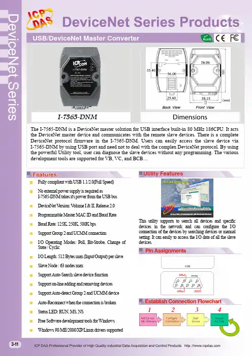
I-7565-DNMThe I-7565-DNM is a DeviceNet master solution for USB interface built-in 80 MHz 186CPU. It acts the DeviceNet master device and communicates with the remote slave devices. There is a complete DeviceNet protocol firmware in the I-7565-DNM. Users can easily access the slave device via I-7565-DNM by using USB port and need not to deal with the complex DeviceNet protocol. By using the powerful Utility tool, user can diagnose the slave devices without any programming. The various development tools are supported for VB, VC, and BCB…Fully compliant with USB 1.1/2.0(Full Speed)No external power supply is required asI-7565-DNM takes it's power from the USB busDeviceNet V ersion: Volume I & II, Release 2.0Programmable Master MAC ID and Baud RateBaud Rate: 125K, 250K, 500K bpsSupport Group 2 and UCMM connectionI/O Operating Modes: Poll, Bit-Strobe, Change ofState / CyclicI/O Length: 512 Bytes max (Input/Output) per slaveSlave Node : 63 nodes maxSupport Auto-Search slave device functionSupport on-line adding and removing devicesSupport Auto-detect Group 2 and UCMM deviceAuto-Reconnect when the connection is brokenStatus LED: RUN, MS, NSFree Software development tools for WindowsWindows 98/ME/2000/XP/Linux drivers supportedThis utility supports to search all devices and specificdevices in the network and can configure the I/Oconnection of the devices by searching devices or manualsetting. It can easily to access the I/O data of all the slavedevices.Utility FeaturesPin AssignmentsEstablish Connection Flowchart3-11HardwareCPU80186, 80 MHz or compatible SRAM/Flash/EEPROM 512 KB / 512 KB / 16 KB ESD Protection2 kV class ACAN InterfaceController NXP SJA1000T with 16 MHz clock Transceiver NXP 82C250 Channel number 1Connector9-pin male D-Sub (CAN_GND, CAN_L, CAN_SHLD, CAN_H, CAN_V+, N/A forothers)Baud Rate (bps) 125 k, 250 k, 500 k Transmission Distance (m) Depend on baud rate (for example, max. 1000 m at 50 kbps ) Isolation 3000 V DC for DC-to-DC, 2500 Vrms for photo-couple Terminator Resistor Jumper for 120 Ω terminator resistor Specification ISO-11898-2, CAN 2.0A and CAN 2.0B Protocol DeviceNet Volumn I ver2.0, Volumn II ver2.0USB InterfaceConnectorUSB Type B Transmission speed 921.6 kbpsSpecificationUSB 1.1 and USB 2.0LEDRound LEDPWR LED, RUN LED, NS LED, MS LEDSoftwareDriver Windows 98/ME/NT/2K/XP/7 Library VB 6.0, VC++ 6.0, BCB 6.0PowerPower supplyBy USB interface Power Consumption3 WMechanismInstallation DIN-Rail Dimensions 72mm x 101mm x 33mm (W x L x H)EnvironmentOperating Temp. -25 ~ 75 ℃ Storage Temp. -30 ~ 80 ℃Humidity10 ~ 90% RH, non-condensingI-7565-DNM-G CR USB / DeviceNet Master Converter Module (RoHS)LED DescriptionRUN LED Indicates the firmware statusMS LED Indicates any slave devices which is disconnecting with the I-7565-DNM NS LEDIndicates that there are errors on the busApplicationOrdering InformationLED indicatorsDeviceNet Messaging3-12。

C A N-U S B转换器的使用手册转换器的使用方法本章主要介绍转换器的使用,包括附带转换器发行的软件包的内容,驱动程序的安装说明,配置文件生成器使用说明和主控程序使用说明。
一.转换器发行包介绍随转换器发行的软件主要有:驱动程序、配置文件生成器、主程序和使用说明等。
如图1所示。
图1 发行包内容二.驱动程序安装说明首次使用本转换器,需要安装驱动程序,打开图1-a中Driver文件夹,如图2所示。
图2 驱动程序内容双击图2中最后一个图标开始安装,如图3所示。
图3 驱动程序安装过程点击“Install”即可完成安装。
三.配置文件生成器使用说明配置文件生成器是用于生成主控程序加载的配置文件的程序。
打开图1-a 中第2个文件夹,内容如图4所示。
图4 配置文件生成器软件包双击图4中选中的可执行文件,即可运行配置文件生成器。
下面主要介绍配置文件生成器的使用。
配置文件生成器可生成3中配置文件,分别是RS232配置文件,CAN配置文件和RS485配置文件,其后缀为“.cm”。
程序主界面如图5所示。
图5 配置文件生成器主界面配置文件生成器中的设备模式分别对应着上述的三种配置文件。
点击下一步即可对转换器的相应模式进行配置。
其中RS485和RS232较为常见,可配置相包括波特率、数据位个数、校验位和停止位。
CAN配置较为复杂,下面着重介绍。
图6 CAN模式比特率配置项图6中的配置项是对CAN设备的比特率进行配置,CAN总线上所有器件都必须使用相同的比特率,对采用不同时钟频率的的器件,应通过适当设置波特率预分频比以及每一时间段中的时间份额的数量来对比特率进行调整。
在CAN 规范中,标称比特率(Nominal Bit Rate, NBR)定义为在不需要再同步的情况下,理想发送器每秒发送的位数。
它可以用公式1表示(其中t bit 标称位时间)。
公式1 NBR计算公式标称位时间(Nominal Bit Time, NBT)(tbit)由互不重叠的段时间段组成,如图7所示。
HighTek HU-05USB转CAN总线接口适配器使用说明书总目录第一章产品简介 (3)1.1概述 (3)1.2性能与技术指标 (3)1.3典型应用 (3)1.4产品销售清单 (4)1.5技术支持与服务 (4)第二章外形与接口描述 (5)2.1硬件接口描述 (5)2.2出厂配置 (5)第三章驱动安装与工具软件 (6)3.1驱动程序安装 (6)3.2CANTools软件安装与使用 (7)3.3CANTools试软件功能介绍 (10)第四章用户程 (12)4.1函数库中的数据结构定义 (12)4.2接口函数说明 (15)4.3接口库函数使用方法 (22)4.3.1VC调用动态库的方法 (22)4.3.2VB调用动态库的方法 (22)第五章附录 (25)附录1:CAN2.0B协议帧格式(可参考SJA1000CAN控制器) (25)第一章产品简介1.1概述HIGHTEK HU-05USB-CAN USB转CAN总线接口适配器是带有1路CAN接口和一路USB2.0接口的智能型CAN总线接口适配器,可进行双向传送。
采用该接口适配器,PC(或其他以太网设备)可以通过RJ45接口连接一个标准CAN网络,构建现场总线测试实验室、工业控制、智能楼宇、汽车电子等领域中数据处理、数据采集、数据通讯网络的CAN核心控制单元。
USB-CAN接口适配器可以被作为一个标准的CAN节点,是CAN总线产品开发、CAN总线设备测试、数据分析的强大工具;同时,USB-CAN接口适配器具有体积小、方便安装等特点,也是便携式系统用户的最佳选择。
USB-CAN接口适配器产品可以利用开发商提供的CANTools工具软件,直接进行CAN总线的配置,发送和接收。
用户也可以参考我公司提供的DLL动态连接库、例程编写自己的应用程序,方便的开发出CAN系统应用软件产品。
USB-CAN接口适配器设备中,CAN总线电路采用独立的DCDC电源模块,进行光电隔离,使该接口适配器具有很强的抗干扰能力,大大提高了系统在恶劣环境中使用的可靠性。
When the I-7565 receives a valid message with the ASCII strings format, it converts this message into a CAN message and transmits it into the CAN network. Based on the same reasoning, when a CAN message is received via the I-7565, the message will be transferred to a message by using the ASCII strings format through the USB port.2. Hardware InstallationUsers need to make a hardware connection between the CAN devices before the application. The details of this are illustrated below: Step1: Set-up the 120Ω terminator resistor of module A and B.Before you continue, if you have changed the settings from default then it is necessary to open the cover for each I-7565 and re-configure their JP3 jumpers to enable them again, as shown in below figure. However if the I-7565’s still have their default settings then it is not necessary to open and reset them because the default configuration is enabled.Enable (default),(Activate)Step2: USB connectionConnect the USB ports of the I-7565 A and I-7565 B to the USB on the PC respectively.Step4: CAN bus connectionConnect the CAN ports of these two I-7565 modules by using the following structure.①②③Step4: Click the “Ok” button. If this process is successful, the I-7565 Utility shows the I-7565 A communication information as below.Step5: In order to match the USB parameters on the PC, please configure the USB parameters of the I-7565 A as follows:Add Checksum: NoError Response: NoStep6: Set the CAN baud rate of the I-7565 A. Here, this testing uses 125K bps.Step7: Click the “Setting” button to save these parameters into the EEPROM of the I-7565 A.Step8: Repeat Steps 1 to 7 to configure the I-7565 B converter with the same parameter settings as the I-7565 A.4. Testing the I-7565s by using the I-7565 UtilityStep1: Set the Init/Normal switches on the back of the I-7565 A and I-7565 B to the “Normal” position. Then, turn on the DC power. TheON LED of the I-7565 A and B will always be turned on. It meansthese two I-7565 converters are working in the operation mode. Step2: Run the I-7565 Utility, I7565.exe, two times. Then duplicate I-7565 windows will be displayed on the screen. One is named as Utility Aand the other is called Utility B.Step3: Select the “Test” tab and click the “Connect” icon on the tool bar of Utility A and Utility B to configure the USB Port1 and the USBPort2 on the PC. The COM1 and COM2 ports on the PC will beused for connecting with the I-7565 A and B converters, respectively.Step4: After selecting the necessary Com port and baud rate, click the “Ok” button on Utility A and B, respectively. Then, Utility A isshown in the below figure and Utility B will be similar to Utility A.Step5: Check the “Use CAN Message” checkbox and input the value to the “CAN Message” frame on Utility A. Click the “Send” button.Then, the Utility will automatically transfer these CAN messages to④②③Step6: Similarly, the user can directly type the command string, “t0013AABBCC”, into the EditBox on Utility B. Click the “Send”button to send this command to I-7565 B via the PC’s USB port.When the user sends the message, Utility B will add the ASCII0x0d to the end of the command string filed in the EditBox. Then Utility A Utility B③①②。
快速入门指南1. 介绍本手册将介绍I-7540D 的快速及简易使用方法,本手册仅提供基本的操作指南。
您若对I-7540D 需要更详细操作说明,请参阅 ICPDAS 光盘(Fieldbus_CD:\CAN\Converter\I-7540D\manual)或至ICPDAS 网站中(/products/Remote_IO/can_bus/i-7540.htm)取得I-7540D 使用手册。
我们帮助用户快速地熟悉以太网络(Ethernet)与CAN 之间信号转换器。
在此,使用二个I-7540D 模块 (分别为I-7540D_A 与I-7540D_B)来说明如何操作I-7540D 模块。
2. 硬件安装在操作之前,用户需确认各个装置之间的链接,详细说明如下:Step 1: 终端电阻的设定在模块A 及B 设定120Ω(奥姆)之终端电阻。
注意:如果您已改变出厂的默认值,请打开I-7540D 模块外壳并且将内部JP3 Jumper 调至Enable。
(JP3预设为Enable)Step 2: 与电源供应器的连结将I-7530A_A 与I-7530A_B 的电源(+VS-图中红线)与接地(GND-图中黑线)接脚连接至直流电源供应器(10~30VDC)。
Step 3: 与以太网络的连接使用两条标准规格的网络线,分别将I-7540D_A 、I-7540D_B 和计算机的网络配接卡(NIC)连接至同一个集线器(Hub)上。
Step 4: 与CAN 总线的连接连接二个I-7540D 模块的CAN 接脚,请依照下图结构所示连接:Enable (default), (Activate)3. I-7540D 参数配置在测试I-7540D转换器之前,使用者需藉由I-7540D工具软件(可在附赠光盘找到)来配置网络与CAN的参数,其详细程序如下所述:Step 1:I-7540D的网络参数默认值如下:IP地址: 192.168.255.1网络屏蔽(Mask): 255.255.0.0网关(Gateway): 192.168.0.1在与I-7540D通讯之前,必须确认计算机与I-7540D同在一个局域网络下(LAN)。
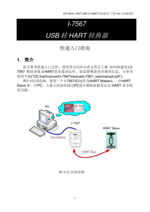
Quick Start User Guide1. IntroductionThis manual introduces the I-7567’s basic setting and operation. The user can refer to the user manual in the ICP DAS companion CD-ROM (Path:“CD:\hart\convert\I-7567\manual\I-7567_quickstart_v1.0.pdf”) for detail. The manual is intended to help users quickly understanding and easily using of I-7567. We use a I-7567 (as a HART master), one HART slave and one PC to make a simple application here, as shown in figure 1. The PC is prepared for setting and operating the I-7567.Figure 1: Application example2. Hardware InstallationUsers may need to make a hardware setting before the application. The detailed illustration is as below :[ Step1: USB connection & Install I-7567 Driver]Connect the USB ports of the I-7567 to PC respectively. Then users can refer to the “Driver Installation” chapter in the user’s manual to complete the I-7567 driver installation.[ Step2: Check the LED Indication I-7567] If the driver install success, the PWR LED is on.[ Step3: Open or close the 250Ω resistor]The user can sets the DIP switch to open resistor as Figure 2-1 or close resistor as Figure 2-2. The factory default settings is set “Off”.Figure 2-1: Close Internal Resistor Figure 2-2: Open Internal ResistorLED Name Power off No Driver Firmware Updating FirmwareOperationReceivingHART Framefrom PCReceiving HART Frame from HART DevicePWR LED off flash off on on on Tx LED off flash off off flash off Rx LEDoff flash off off off flash[ Step4: HART bus connection ]Connect the HART port of the I-7567 to HART Device.3. Using I-7567 UtilityStep1: Set the resistor on the back of the I-7567 and turn on the DC power. The PWR LED of the I-7567 will be always turned on. It means the I-7567 converters are working in the “Firmware Operation” mode.Step2:Run the “I-7567 Utility”, HC_Tool.exe, and configure theconnection parameters(please check the virtual com port numberFigure 3-1) and then click the “Settings” of menu like Figure 3-2.Figure 3-1: The Virtual COM Port NumberFigure 3-2: Open the “Settings” of menu Step3:Set “Port Name” and “Auto Configure“ like Figure 3-3.Figure 3-3: Set Com Port and HART statusStep4:Click the “Open” button to connect to the I-7567 module after closing “settings” like Figure 3-4.Figure 3-4: Click the “Open” buttonStep5: The I-7567 connected HART device with HART bus, then click the “Start” button to search the HART devices. The users can view “Information” to understand the status of HART device.。
快速指南● 简介本篇使用者指引手册主要目的是要教导使用者如何快速又方便的使用PROFI-8155/8255到你们的应用范例上,因此只提供简单的操作说明。
若需要更详尽的使用说明,请参考在ICP DAS 光盘中或ICP DAS 网页上的PROFI-8155/8255的使用者手册。
● 硬件结构与外观● 连接器与接脚说明PROFIBUS 连接器是采用9-Pin D-Sub 的接头,只有四根接脚有使用。
其中VP 与GND 是由PROFI-8x55提供5V 电源给偏压式终端电阻。
而A-Line/B-Line 则是连接PROFI-8x55内部的高速RS-485驱动IC 。
接脚编号信号 描述3 B-Line 传送/接收 正(+)端5 GND 主动式终端电阻-电源接地6 VP 主动式终端电阻-电源5伏特8 A-Line 传送/接收 负(-)端状态指示LEDPROFI-8x55提供了三个状态显示LED,分别是PWR(黄色)、ERR(红色)与RUN(绿色)。
当PROFI-8x55开机时,PWR灯会亮起;在参数化以及规划的过程中,ERR灯会亮起;进入数据交换模式后,RUN的灯号就会亮起,ERR的灯号会熄灭。
以下是状态指示LED的联机状态表。
状态指示器状态叙述除错方针ERR-亮(ON) & RUN-灭(OFF) 尚未联机(Offline Mode*)检查主端设定的PROFI-8x55 节点地址是否与的旋转开关一致。
ERR-快速闪烁(每隔0.1秒) 速率已侦测(Stop Mode*)设定Master进入OperateMode或Clear ModeERR-每隔0.5秒闪烁参数数据错误安装与设定不符(注1) ERR-每隔1秒闪烁规划数据错误安装与设定不符(注2)ERR-亮(ON) & RUN-亮(ON) 清除模式(Clear Mode*)改变主端的模式从ClearMode到Operate ModeERR-灭(OFF) & RUN-亮(ON)数据交换模式(Operate Mode*)PWR-每隔1秒闪烁模块脱机确认模块是否故障并更换PWR & ERR 每隔1秒同时闪烁开机前未安装任何模块or 模块脱机(损坏或拔除)确认模块安装是否确实或模块是否故障PWR,ERR每隔0.5秒交错闪烁诊断信息回报(Diag)检查模块输出入是否超出范围或温度传感器断线终端电阻为了减少信息在PROFIBUS总线(总线)上的反射效应,PROFIBUS总线上需安装终端电阻于起始与结束站台上,其电阻配置请参照上图所示,VP 接至电源5伏特,GND接至电源0伏特。
快速入门指南
1. 简介
本手册将介绍I-7565-H1/ I-7565-H2模块的快速及简易使用方法。
手册
仅提供基本的操作指南;若您需要更详细操作说明文件,可在随机附赠的
光盘中找到,或至泓格科技公司网站取得。
(/products/Remote_IO/can_bus/i-7565-H1H2.htm)
为了帮助使用者快速地熟悉I-7565-H1/H2模块。
在此,我们使用二个I-7565-H1模块(分别为I-7565-H1_(A)与I-7565-H1_(B))来展示如何操作I-7565-H1模块。
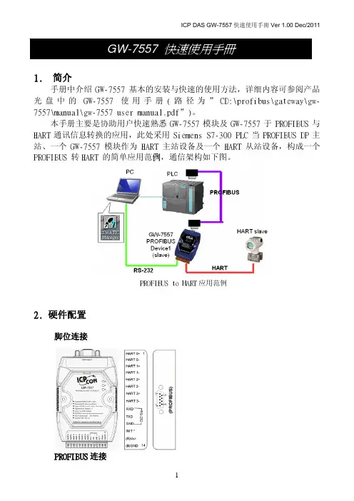
其范例网络架构如下图所示:
图 1-1:展示范例之网络架构
2. 硬件安装
在实际应用之前需先确认各项硬件的设定,详细的说明如下列步骤所示:
[ 步骤1: USB 传输线与安装I-7565-H1驱动程序 ]
分别将I-7565-H1_(A)与I-7565-H1_(B)以USB 传输线链接到计算机的USB 端口上。
然后,您可以参阅使用者手册的“Driver Installation”章节,以顺利完成I-7565-H1驱动程序的安装。
[ 步骤2: 启用模块A 与B 的120Ω终端电阻 ]
请打开I-7565-H1的背板,确认JP3 jumper 是否像图2-1所示,在位置1与位置2上。
图 2-1: JP3 Jumper 位置
[ 步骤3: CAN 总线的连接 ]
将两个I-7565-H1模块(A 与B)的CAN 口,以图2-2的连接形式连接。
图 2-2: CAN 总线的连接 致能端子
(默认值=启用)
3. 使用I-7565-H1/H2 Utility测试I-7565-H1
步骤1:将I-7565-H1_A 与I-7565-H1_B背面的Init/Normal开关调整至”Normal”的位置,然后打开DC电源供应器。
I-7565-H1_A 与I-
7565-H1_B的电源指示灯(PWR Led)将亮起,代表二个I-7565-H1
转换器模块在“Firmware Operation”模式下正常动作。
步骤2: 执行“I-7565-H1/H2 Utility”(I-7565-H1H2_Utility.exe),并设定相关的联机参数、接着点击【Connect】键,以联机至I-7565-H1_A 模
块,其相关的联机参数如图3-1所示。
Port No : 虚拟COM口编号【Port3】。
(对应到图3-2)
Mod Name: 模块名称【I-7565-H1】。
Port Enable: 勾选【Port 1】。
Baud Rate: 【1000K】bps。
.
图 3-1: I-7565-H1/H2 Utility的联机参数设定画面
图 3-2:虚拟COM口编号
步骤3:再度执行I-7565-H1/H2 Utility,并联机至I-7565-H1_B模块。
步骤4: 在与I-7565-H1联机成功之后,画面显示与模块通讯内容,且联机参数显示在窗口的状态栏内。
图 3-3: I-7565-H1/H2 Utility的通讯画面
步骤5:
[1]输入CAN封包信息至“SendMsg Configuration”内。
[2]点击【Add】键新增该CAN信息至Utility A和B的“CAN Message
Send Area”内。
[3]点击【Send】键后,utility将透过计算机的USB端口传送该CAN信
息。
在I-7565-H1_A接收到由计算机的USB端口所传送的CAN信息之后,它将该笔CAN信息传递至自身的CAN口;所以,I-7565-H1_B接收到该笔CAN信息之后,也将它传递到自身的USB口上,进而传送给计算机的USB端口,其流程如图3-4与图3-5所示:
图 3-4: I-7565-H1_A Utility画面图 3-5: I-7565-H1_B Utility画面
4. 指示灯
I-7565-H1/H2提供三个指示灯让用户了解模块目前的运作情况。
接下来,说明三个指示灯号的意义。
图4-1标示三个指示灯的位置。
(1) PWR LED :
PWD LED可以帮助使用检查I-7565-H1/H2是否运作中。
若模块处于“firmware operation”模式,则PWR LED显示常亮。
然而,当模块处于“firmware updating”模式时,该PWR LED将以每秒一次的频率闪烁。
(2) RUN LED :
RUN LED显示I-7565-H1/H2目前为传送/接收CAN信息的状态。
当传送/接收到一笔CAN信息时,RUN LED将闪烁一次。
I-7565-H2的CAN1口与 CAN2口共享同一 RUN LED。
(3) ERR LED :
ERR LED显示目前是否有错误发生。
ERR LED在正常情况下是不亮的;反之,当发生Bus-Off错误发生时, ERR LED将亮起,直到Bus-Off 的错误情况被排除。
若内建于I-7565-H1/H2 CAN/USB 缓冲存储器超载时、或是传送CAN信息失败,则ERR LED将连续性的闪烁。
I-7565-H2的CAN1口与 CAN2口共享同一 ERR LED。
图 4-1: I-7565-H1/H2 灯号位置
表 4-1: I-7565-H1/H2 指示灯号意义
LED Name I-7565-H1/H2 状态 LED状态
所有指示灯硬件初始化失败所有指示灯在重置后永远恒亮硬件看门狗失效所有指示灯以每2
秒闪烁一次
请联络我们
所有指示灯以每300毫秒轮流
闪烁
PWR LED Firmware Updating 模式每秒闪烁一次Firmware Operation 模式常亮
电源关闭常灭
RUN LED 传输中闪烁一次Bus Idle 常灭
ERR LED 传输失败每100 ms闪烁一次缓冲区超载每秒闪烁一次
Bus-Off 常亮
No Error 常灭
5. 软件开发工具之控制流程图
下图说明了如何使用泓格科技公司开发的软件开发工具(Software Development Kit, SDK)来发展上层的应用程序之流程图,在随机附赠的光盘中,您可以找到该SDK的相关档案(VCI_CAN.dll、VCI_CAN.lib与其宣告檔VCI_CAN.h)。
图5-1: SDK提供的API控制流程图
6.故障排除
下述是常见使用I-7565-H1/H2模块的问题。
若这些Q&A无法帮助您解决问题时,请联络我们。
6.1 如何使用I-7565-H1/H2 ?
请依照下列步骤完成I-7565-H1/H2的操作。
(1) 将USB传输线插入计算机USB端口和I-7565-H1/H2模块。
(2) 安装I-7565-H1/H2 驱动程序。
(3) 执行I-7565-H1/H2 Utility之后,选择【virtual com port】、【module
name】、【CAN baud rate】之后,联机至I-7565-H1/H2 模块。
(4) 使用I-7565-H1/H2 Utility传送/接收CAN信息或是设定模块的参数。
6.2 I-7565-H1/H2的最大数据传输率是多少?
I-7565-H1/H2最大数据传输率可达每秒3000资料讯框(frame)。
但在一些处理速度较慢的计算机上,若以每秒3000笔速率接收数据讯框时,可能会造成遗失的问题。
为此,我们在I-7565-H1/H2 Utility提供一可自行调整数据传输速率的功能,以解决高速传输模式下,造成数据讯框遗失的问题。
6.3 一台计算机可安装多少台I-7565-H1/H2模块?
理论上,是没有任何数量上的限制。
市面上的操作系统皆提供多任务运作模式,可支持多数I-7565-H1/H2模块的连接,但效率取决于计算机硬件的效能。
※※※感谢您使用本公司产品※※※
权利声明和友善提示
承诺
郑重承诺:凡泓格科技股份有限公司产品从购买即日起一年内无任何材料性缺损。
权利声明
泓格公司拥有本手册的所有权利,包括泓格公司的专利、著作权等产权利益。
任何团体或个人,未经泓格公司明确的授权,不得复制、传播或使用本手册全部或其中的内容进行商业活动,违者将要对造成的任何损失承担责任。
免责声明
凡使用本系列产品除产品质量所造成的损害,泓格科技股份有限公司不承担任何法律责任。
泓格科技股份有限公司有义务提供本系列产品可靠而详尽资料,但保留修订权利,且不承担使用者非法利用资料对第三方所造成侵害构成的法律责任。
安全导则
在系统最终调试之前,您应该对控制设备进行完整的控制功能测试和必要的安全性能测试。
您在安装、调试、试运行控制设备的过程中,应保证系统涉及或可能涉及设备的安全运行。
由于不可预见的设备错误或操作错误随时可能发生,您在操作中应提高警觉,避免造成此类危及人身安全或设备损害的事件。
商标
手册中所涉及所有公司商标,商标名称及产品名称分别属于该商标或名称的拥有者所有。
版权
版权所有 © 1999-2012泓格科技股份有限公司,保留所有权力。