PLT R125抛绳器
- 格式:doc
- 大小:48.50 KB
- 文档页数:2

一、实验目的1. 了解抛石机的基本原理和构造。
2. 学习抛石机的制作方法,提高动手能力。
3. 通过实验,掌握抛石机的使用技巧,提高实验技能。
二、实验原理抛石机是一种利用弹性势能将石块抛射出去的装置。
其基本原理是利用弹弓的弹性将石块弹出,弹弓的弹性势能转化为石块的动能,从而使石块具有较大的初速度,从而实现远距离抛射。
三、实验材料与工具1. 材料:竹条、橡皮筋、石块、胶带、剪刀、螺丝刀等。
2. 工具:尺子、铅笔、锤子、扳手等。
四、实验步骤1. 制作弹弓(1)将竹条剪成两段,一段作为弹弓的主体,另一段作为弹弓的尾部。
(2)在弹弓的主体上标记出弹弓的两个支点,然后用铅笔在支点处画线。
(3)将橡皮筋套在弹弓的两个支点上,用胶带固定。
(4)将弹弓的尾部与主体连接,确保连接牢固。
2. 制作抛石机(1)将弹弓的主体固定在抛石机的支架上,确保弹弓可以自由伸缩。
(2)在抛石机的支架上安装一个投掷装置,如一个可调节高度的支架。
(3)将石块放置在投掷装置上,调整支架高度,使石块与弹弓的距离适中。
3. 实验操作(1)将橡皮筋拉伸至最大长度,确保弹弓的弹性势能最大化。
(2)将石块放置在弹弓上,确保石块与弹弓的距离适中。
(3)用力将橡皮筋压缩,使弹弓的弹性势能转化为石块的动能。
(4)释放橡皮筋,观察石块的抛射效果。
五、实验结果与分析1. 实验结果通过实验,我们成功制作了一台抛石机,并进行了多次抛射实验。
实验结果显示,抛石机可以将石块抛射到一定距离,抛射效果较好。
2. 结果分析(1)抛石机的抛射距离与弹弓的弹性势能、石块与弹弓的距离、橡皮筋的拉伸长度等因素有关。
在实验过程中,我们通过调整这些因素,实现了较远的抛射距离。
(2)抛石机的制作过程中,需要注意弹弓的固定和橡皮筋的拉伸,以确保抛射效果。
六、实验总结通过本次实验,我们成功制作了一台抛石机,并掌握了抛石机的使用技巧。
在实验过程中,我们学习了抛石机的基本原理和构造,提高了动手能力。

2 000-2 500 KGRP2.0N-RP2.5NRIDER PALLET TRUCKWaRl 6b 1l 2a/2A stb 12b 11b 5ea/2yxh 13h 3l 1b 10h 7(614)(1353)c(177)m 2s(173)lQSpecification data is based on VDI 2198RP2.0N, RP2.5NTRUCK DIMENSIONS1.1 Manufacturer (abbreviation) 1.2 Manufacturer’s type designation1.3 Drive: electric (battery or mains), diesel, petrol, fuel gas 1.4 Operator type: hand, pedestrian, standing, seated, order-picker 1.5 Rated capacity/Rated load Q (t)1.6 Load centre distance <c (mm)1.8Load distance, centre of drive axle to fork <x (mm)1.9 Wheelbase < y (mm)2.1 Service weight < kg 2.2 Axle loading, laden front/rear kg 2.3 Axle loading, unladen front/rearkg3.1 Tyres: polyurethane, topthane, vulkollan, front/rear 3.2 Tyre size, front ø (mm x mm)3.3 Tyre size, rearø (mm x mm)3.4 Additional wheels (dimensions)ø (mm x mm)3.5 Wheels, number front/rear (x = driven wheels) 3.6 Tread, frontb 10 (mm)3.7 Tread, rear < b 11 (mm)5.1 Travel speed, laden/unladen km/h 5.1.1 Travel speed, laden/unladen, backwardskm/h 5.2 Lift speed, laden/unladen m/s 5.3 Lowering speed, laden/unladen m/s 5.8 Max. gradeability, laden/unladen%5.9 Acceleration time, laden/unladen (forks trailing) s5.10 Service brake6.1 Drive motor S2 60 minute rating kW 6.2 Lift motor, S3 15% ratingkW 6.3 Battery according to DIN 43531/35/36 A,B,C, no 6.4 Battery voltage/nominal capacity K5V/Ah6.5 Battery weight q kg 8.1 Type of drive unit 10.7 Sound pressure level at the driver’s seat dB (A)4.4 Lifth 3 (mm)4.8 Height of seat / platform h 7 (mm)4.15 Height, lowered h 13 (mm)4.19 Overall length < l 1 (mm)4.20 Length to face of forks l2 (mm)4.21 Overall widthb 1 / b 2 (mm)4.22 Fork dimensions DIN ISO 2331 < s/e/l (mm)4.25 Distance between fork-arms < b 5 (mm)4.32 Ground clearance, centre of wheelbase m 2 (mm)4.33 Load dimension b 12 × l 6 crossways b 12 × l 6 (mm)4.34Aisle width predetermined load dimensionsA st (mm)4.34.1 Aisle width for pallets 1000mm x 1200mm crossways < † A st (mm)4.34.2 Aisle width for pallets 800mm x 1200mm lengthwise < † A st (mm)4.35 Turning radius < Wa (mm)4.43 Step heighth 7 (mm) 1010 10101202 1808 1314 2196 755 255 755 255 Vulkollan VulkollanVulkollan Vulkollan254 x 90 254 x 90 85 x 90 85 x 90 150 x 60150 x 601x + 141x + 14492 492 346 346 9.5 12.5 9.5 12.5 9.5 9.5 9.5 9.5 0.027 0.037 0.020 0.037 0.064 0.030 0.064 0.030 10.0 24.5 8.3 24.5 6.6 4.8 7.1 4.8Electro MagneticElectro Magnetic 2.6 2.6 1.2 1.2 no no24 465 24 465366366 0.40.4AC Controller AC Controller69.5 69.5120 120907 293 907 293 85 85 1996 1996 840 840 798 798 60 184 1156 60 184 1156530 530 25 25800 x 1200800 x 12002465 2465 D I S T I N G U I S H I N G M A R K SW E I G H T ST Y R E S / C H A S S I SD I ME N S I O N SP E R F O R M A N C E D A T AL E C T R I C E N G I N ED R I VE /L IF TM E C H A N I S MA D D I T I O N A LD A T ARP2.0N RP2.5N Battery Battery Stand Stand 2.0 2.5600 s600 s A st = W a + R + a = W a + √ (l 6 - x)2 + (b 12/2)2 + a (see lines 4.34.1 & 4.34.2)a= 200 mmHYSTERHYSTERFORKSSTANDARD EQUIPMENT AND OPTIONSNOTE:Specifications are affected by the conditionof the vehicle and how it is equipped, as well as the nature and condition of the operating area. Inform your dealer of the nature andcondition of the intended operating area when purchasing your Hyster Truck.< See forks table.s Applies to one pallet = 1200 mm.q These values may vary by +/- 5%.¯ Values obtained with 40 cycles †S tacking aisle widths (lines 4.34.1 & 4.34.2)are based on the VDI standard calculation as shown on illustration. The BritishIndustrial Truck Association recommends the addition of 100 mm to the totalclearance (dimension a) for extra operating margin at the rear of the truckT he battery weight in the table refers to Sunlight battery. The battery weight may change according to supplier: Enersys 381 kg | Midac 393 kgFORKS TABLESU W ith forks lowered. With forks raisedadd 68mm.¡ Aisle width for pallets lenghtwise.z All weights are: forks + tie rods.Þ For models RP2.5N +22 Kg.À For models RP2.5N +16 Kg.STANDARD EQUIPMENT AND OPTIONS x Standard equipment o Optional equipmentSPED - Special Products Engineering DepartmentNOTICECare must be exercised when handling elevated loads. When the carriage and/or load is elevated, truck stability is reduced. It is important that the mast tilt in either direction is kept to a minimum when loads are elevated.Operators must be trained and must read, understand and follow the instructions contained in the Operating Manual.All values are nominal values and they are subject to tolerances. For further information, please contact the manufacturer.Hyster products are subject to change without notice. Lift trucks illustrated may feature optional equipment.Values may vary with alternative configurations.Safety:This truck conforms to the current EU requirements.Cl x U l-x l 6 b 12 R y U l 2 l 1 Wa U a A st ¡ Forks weights zb 5 = 480 - 530 - 560 - 670 mm b 11 = 296 - 346 - 376 - 486 mmmm 50060070080010001100120012001500100011001200mm 100611561406159619562156235623562856195621562356mm 191191441545551751951496996600800706mm 100012001400160020002200240024003000200022002400mm 8001000800800120080080080012001200800800mm 44155259167984589010726721288880934850mm 229625572596277032903335351735724188327633303540Kg 147156165173204.5212.5220.5229 Þ249 Þ205.5213.5227 Àmm 184619962246243627962996319631963696279629963196mm 1655180518912245270021962490mm840840mm200200mm 14781628171420682523252320192313mm 81596510511405186013561650UKSHORT LONGFor all batteriesFEATURE Grab handle Seat with seat/lean system Multifunctional Display Keyless accessRocker Switch Directional Control Mini lever hydraulic controlSecondary lever for double pallet handling Fixed steering wheel Standard steering Reverse steeringFEATUREChassis width (max) 798 mm Fork Carriage widths 480 mm 530 mm 560 mm670 mm Fork Carriage lenghts 1006 mm 1156 mm 1406 mm 1606 mm 1965 mm 2156 mm 2356 mm2856 mmBattery sizes792 x 212 x 814 mmFEATURETravel speed 9.5 km/h reverse Travel speed 12.5 km/h forward Speed slow down on corneringAudible alarm (choice of forks leading, forks trailing, both travel directions) Electrical horn Error codes on display Lift cut out by sensor Multipurpose barBeverage holder and document tray A4 clipboard Stretch film roll holder Work lights x 1 (pallet facing) Rubber bumper SPED SPED Cold store protection - 30° C Twin battery change station (fixed) Side battery change - battery tray rollers Extension cableSingle polyurethane load wheel Tandem polyurethane load wheels Vullokolan drive tyre Topthane PU75 drive tyre Wet surface drive and load wheels Antistatic drive tyre Rubber drive tyre Standard Castor wheel Sprung Castor wheel DC/DC converter 12V 2,5A Load guard (1800 mm)RP2.0N RP2.5Nx x x x x x o o x x x x o o x x x x ooRP2.0N RP2.5Nx x o o o o x x o o o o x x o o o o o o o o o o o o xxRP2.0N RP2.5Nx x x x x x o o x x x x x x x x x x o o o o o o SPED SPED o o o o x x o o x x o o x x o o o o o o o o x x o o o o ooTall operator in sitting position Short operator in sitting positionTall operator in leaning positionShort operator in leaning positionTall operator in standing position Short operator in standing positionO P E R A T O R C O M P A R T M E N TO P E R A T O R C O M P A R T M E N TO P E R A T O R C O M P A R T M E N TThe new tough Hyster® Rider Pallet Truck is designed for efficiency for operations at medium to long distances. It has excellent manoeuvrability, control and visibility. The all-new Rider Pallet Truck is built with the quality hallmarks of Hyster: tough, intelligent, dependable and efficient. DEPENDABILITYn N ew Rider Pallet T ruck feature modular design of frame, operator compartment and fork carriage.n C ompletely welded stiff and strong base frame is available in 798mm width, with choice of 4different fork widths and 8 different lengths tomatch demanding applications requirements.n T he bumper is a single piece 10mm thick construction - no splits or bolted joints, to reducepotential service risk.n T he side panels made from 5mm pressed steel are built into the exterior of truck to reduce riskof damage.n P arts commonality with other Hyster products, with proven reliability and durability. PRODUCTIVITYn T he new, improved Hyster traction motor gives powerful acceleration and has an increased travel speed of up to 12.5km/h.n T wo different steering modes: Standard steering and Reverse steering as option.n F ull AC infrastructure on drive and steering motors allows seamless changes in direction of travel,increasing cycle speeds and the control of pallethandling operations.n A djustable speed reduction on cornering feature provides smooth load handling and precisedirection control.n M ini levers for all hand controlled main hydraulic functions within finger reach position.n T he seat / lean arrangement enables the operator to either sit during long traction runs or lean when operating in back of the trailer. ERGONOMICSn N ew operator compartment layout is optimised for ergonomics and operator space. The low 292mm step height and industry widest 470mm entryprovides improved ingress / egress.n T he new seat design with seat / lean system combines swinging seat cushion with fixedback rest, housed on side panel enabling theadjustment of the seat position between thehorizontal seat and vertical lean / stand by push ofa button.n T he driver comfort is enhanced through introduction of a market leading floor area (0.217m2) allowingoperators to take up various comfortable positions reducing fatigue over long shifts.n S uspended floorplate reduces shocks felt by driver and cushioned floor mat improves comfortfor the driver.n T he operator presence switch, incorporated in floorplate, is designed to ensure that the driver’sfoot is always within the driver compartment.n L eft hand steering with accelerator finger / thumb operation provides option on how driver operates control. Useful for different hand dimensionsand limits fatigue by allowing operator to changeposition throughout the shift.n155mm steering wheel with spinner fixed position is set at 10-degree inclination.n T he hand grip is fixed directly to the frame and does not include any controls ensuring a strongand solid grip.n P osition of display in front of operator allows for easy reading without disturbing visibility.n S torage is available below armrest and in front of drivers legs, while storage for drink bottle isprovided behind the drivers right arm.n T he drive wheel automatically moves to centre position when truck is switched on.PRODUCT FEATURESLOW COST OF OWNERSHIPn T he new Hyster 2.6 kW traction motorgives powerful acceleration and an increasedtravel speed for superior performance andincreased productivity.n T raction motor and controllers are fitted withforced air cooling as standard to reduce thermaleffects on parts and maintain high performanceand efficiency.n R egenerative braking recovers energy andincreases breaking effect to help reducemaintenance costs.n T rucks are rated to IP65 standard, for protectionagainst dust and water ingress.n H igh level of parts commonality with other Hysterproducts with proven reliability and durability forease of maintenance.SERVICEABILITYn S ide panels are bolted to the frame enablingremoval for service or replacements.n T he MDU is bolted on frame allowing singleremoval and drive wheel can be accessed fromwithin the frame.n H inged floor plate, with gas strut stay enablesquick access to caster wheel and hydraulic unit forinspection or top up of fluids.n T wo diagnostic points within operatorcompartment are conveniently located for easyconnection and all fuses are easily accessible.n S ervice interval for hydraulic oil and filter - 3000h.n S tandard warranty – 24 month (4000 hours),extended warranty – 36 month (6000 hours).www.hyster.eu*********************/HysterEurope@HysterEurope/HysterEuropeSTRONG PARTNERS. TOUGH TRUCKS.TMFOR DEMANDING OPERATIONS, EVERYWHERE.Hyster supplies a complete range of warehouse equipment, IC and electric counterbalanced trucks, container handlers and reach stackers. Hyster is committed to being much more than a lift truck supplier.Our aim is to offer a complete partnership capable ofresponding to the full spectrum of material handling issues: Whether you need professional consultancy on your fleet management, fully qualified service support, or reliable parts supply, you can depend on Hyster.Our network of highly trained dealers provides expert,responsive local support. They can offer cost-effective finance packages and introduce effectively managed maintenance programmes to ensure that you get the best possible value. Our business is dealing with your material handling needs so you can focus on the success of your business today and in the future.HYSTER and FORTENS are registered trademarks in the European Union and certain other jurisdictions.MONOTROL is a registered trademark, and DURAMATCH andare trademarks in the United States and in certain other jurisdictions.A division of NACCO Materials Handling Limited.Printed in England. Part Number: 3990169 Rev.05-08/17-TLCHYSTER EUROPECentennial House, Frimley Business Park, Frimley, Surrey, GU16 7SG, England.Tel: +44 (0) 1276 538500, Fax: +44 (0) 1276 538559。

INSTRUCTION MANUAL125LB (56.8kgs)PUSH SPREADERModel No: THS125 -- Product No: 1938137001ASSEMBLY REQUIREDSAVE THESE INSTRUCTIONSSPARES & SUPPORT: 01793 333212Please read & understand this manual, paying attention to the safety instructions, before use. The manufacturer reserves the right to change the product specification and livery according tocontinued product improvements.Images used are for illustration purposes only01/02/2017CONTENTSSPECIFICATIONIMPORTANT INFORMATIONGENERAL SAFETY INSTRUCTIONSCOMPONENTSASSEMBLYADJUSTMENTSMAINTENANCEOPERATIONRATE SETTINGSPARTS DIAGRAMPARTS LISTWARRANTYNOTESASSEMBLY IS REQUIREDThis product requires assembly before use. See the “Assembly” section for instructions. Please check that all parts required for the assembly of this spreader are included. If for any reason, you believe a part for the assembly is missing or damaged, please contact us.If you require any assistance with regards to the contents or operation ofyour machine, please contact us:TEL: 01793 333212EMAIL:************************************.uk(MON – FRI 8.00AM TO 5.30PM EXCL. BANK HOLIDAYS)DO NOT USE WITH ROCK SALT.Using rock salt in this spreader will damage the mechanism and shorten the life of the product. Refined ice melting salt can be used but the user should be aware that this is not a specialised salt spreader and using salt may corrode the spreader and reduce the life of the machine.Clean the spreader thoroughly after using refined de-icing salt.THSSPECIFICATIONSThe manufacturer reserves the right to change the product specification and livery according to continued product improvements.IMPORTANT INFORMATIONINTENDED USEThe product is intended for spreading granular material for domestic gardens. This product is not intended for commercial use. Generally acknowledged accident prevention regulations and enclosed safety instructions must be observed.Only perform work described in these instructions for use, any other use is incorrect. The manufacturer will not assume responsibility for damage resulting from such use. GENERAL SAFETY INSTRUCTIONSRead and understand the owner’s manual and labels affixed to the product. Learn its application and limitations as well as the specific potential hazards. Retain these instructions for future reference. The operator is responsible for following the warnings & instructions in this manual and on the product.STAY ALERTDo not operate the machine while under the influence of drugs, alcohol, or any medication that could affect your ability to use it properly. Do not use this machine when you are tired or distracted from the job at hand. Be aware of what you are doing at all times. Use common sense.AVOID DANGEROUS CONDITIONSMake sure there is adequate surrounding workspace. Cluttered areas invite injuries. Keep your work area clean with sufficient light. Keep the area around the machine clear of obstructions, grease, oil, rubbish & other debris which could cause persons to fall onto moving parts. INSPECT YOUR MACHINECheck all bolts, nuts & screws for tightness before each use, especially those securing guards & drive mechanisms. Vibration during use, may cause these to loosen.Replace damaged, missing or failed parts before using.Warning labels carry important information. Replace any missing or damaged warning labels.CRUSH AND CUT HAZARDSAlways keep your hands and feet clear from moving parts while operating the equipment. Always keep the work area clean and clear when operating.CONDITIONSWe recommend the machine is not used during winds. This may affect the spreading pattern.DRESS PROPERLYDo not wear loose clothing, gloves, scarfs, neckties or jewellery (rings, wrist watches), which can be caught in moving parts.DO NOT OVERREACHKeep proper footing and balance at all times when using the machine. Never stand on the machine. Serious injury could occur if the machine is tipped or if the moving parts are unintentionally contacted. Do not store anything above or near the machine, where anyone might stand on the machine to reach them.AVOID INJURY FROM UNEXPECTED ACCIDENTKeep hands & feet out of the way of all moving parts. Do not place any part of your body or any tool e.g. in moving parts of the machine during operation.DO NOT FORCE TOOLAlways work within the rated capacity. Do not operate for a purpose for which it was not intended.MAINTAIN YOUR MACHINE WITH CARE Clean the machine immediately after use. Keep the machine clean to ensure it operates to its full & safest performance. When maintaining this machine, only the manufacturer’s original replacement parts should be used. The use of non-original manufacturer parts may invalidate your warranty.PROTECT THE ENVIRONMENTTake left over materials to an authorised collection points or follow the stipulations in the country where the machine is used. Do not discharge into drains, soil or water. STORE IDLE EQUIPMENTWhen not in use, the machine should be stored in a dry location. Keep the machine away from children and others not qualified to use it. OPERATION SPEEDDo not exceed 10mph, to avoid personal injury and/or equipment damage.TYRE INFLATIONBefore operating, make sure the tyres have the recommended pressure of 25 PSI (Do not exceed 25 PSI). We recommend the use of FOOT or HAND manual inflation devices only. This is a garden/domestic product, therefore extended use over abrasive surfaces (e.g. concrete, tarmac etc.) could cause premature wear on the tyres.SAFETY SYMBOLSSafety alert symbol. Used to alert you to potential personal injury hazards. Obey all safety messages that follow this symbol to avoid possible injury.DANGERIndicates an imminently hazardous situation which, if not avoided, will result in serious injury.WARNINGIndicates a potentially hazardous situation which, if not avoided, could result in serious injury.CAUTIONIndicates a potentially hazardous situation which, if not avoided, may result in minor or moderate injury.CAUTIONUsed without the safety alert symbol indicates a potentially hazardous situation which, if not avoided, may result in property damage.KNOW YOUR MACHINERead this owner’s manual before operating the equipment. Familiarize yourself with the location and function of the controls and features. Save this manual for future reference.123 6451.T-Handle –Pushes and moves the spreader easily.2.Flow Control –Controls the flow of material being spread3.Hopper –Do not exceed rated load capacity 125lb (56.8kgs).4.Tyre/Wheel –Do not exceed recommended inflation rated 25 PSI.5.Impeller - Evenly distributes material.6.Support Leg –Stabilizes load and spreader, when stationary.COMPONENTSNOTE: Parts Lists are supplied for information purposes only, not all parts are stocked individually & we recommend you contact our Spares Team on 01793 333212 for expert advice.ASSEMBLYRECOMMENDED TOOLS REQUIRED•Pliers•Adjustable Spanner•8mm Wrench•10mm Wrench•13mm Wrench•14mm WrenchSTEP 1 - Wheels•On the left side of the axle install a wheel bushing and wheel spacer onto the axle.•Slide a wheel over the axle.•Put a Ø16 flat washer over the axle, insert the cotter pin through the hole and secure by bending. •On the right side of the axle slide a wheel bushing and the wheel spacer onto the axle.•Put a wheel over the axle, line up the holes and insert the drive pin through sleeve and lock. •Put a Ø16 flat washer over the axle, insert the cotter pin through the hole and secureNOTE: Four additional flat washers are provided for adjusting the gap between the wheelsSTEP 2 – Support Leg•Position the support leg so the J-shaped end is pointing away from the wheel assembly. •Insert the M8x75 hex bolt through the top hole on the support leg and slide the spacer over the bolt end.•Take the support leg and insert the bolt through the upper cross bar on the mounting assembly and loosely tighten with the M8 lock nut.NOTE: Before tightening the bolt make sure the support leg flange and the lower cross bar holes line up.•Insert M6 x 40 hex bolt through the holes in the flange and cross bar. Use the Ø6 big flat washer and M6 lock nut.Cross BarFlangeSTEP 3 - Hopper•Lower the hopper over the mounting assembly, carefully line up the holes in the bottom of the hopper with the spindle in the mounting plate of the axle.•Use the M6 x 40 hex bolt and Ø6 flat washer to attach the hopper to the mounting assembly and secure with M6 lock nut.•Make sure the gear and pinion gear works smoothly. If not, adjust again until the gear and pinion gear swivel smoothly.•Tighten all the hardware on the shaft support plate and hopper.•Insert the R Pin through the top of the spindle.STEP 4 – Connecting Handle•Slide the handle tube into the top of the support leg and align the two fixing holes.•Insert M6x35 hex bolts through the two holes on the support leg and tighten with the Ø6 spring washer and M6 lock nut.•Insert M6x20 hex bolt through the hole in the side plate and tighten with Ø6 spring washer and M6 lock nut.STEP 5 – Solid Linkage•Connect the solid linkage through the bottom fix plate using the Ø8 flat washer and tighten with an M8 lock nut.•Connect the other end of the linkage to the flow control with an Ø8 flat washer and M8 lock nut. •Install the hopper screen in the bottom of the hopper.•Before using the spreader make sure all the hardware is tightened.•Use the rain cover as needed to protect material in the hopper or when spreader is being stored.ADJUSTMENTSSTEP 6When you have finished all the above steps, if the hole at the bottom of hopper cannot be closed and opened completely by using the handle you may need to the follow these additional steps. •The handle adjusts the spreader setting. When the handle is moved to “30”, the adjustable plate is fully open, when at “0”, it is fully closed.•Loosen the wing nut on the Bracket and move the adjustment lever handle up or down depending on the amount of material required. Pushing the handle down will release more material and pulling the handle up will stop the flow entirely.•Tighten the wing nut when the desired position is reached.To operate this spreader, push the handle to the lowest position (downwards). You may move the position of the Wing nut on the Gauge & Lever to adjust the space on the hole between the hopper and the adjustable plate as per your need when spreading.OPERATIONDANGERThe product must only be put into operation if no defects are found. It is crucial that any defective parts are replaced before the product is used again. Check the safety equipment and the safe condition of the product. Check all parts to make sure that they fit tightly. Check whether there are any visible defects: broken parts, cracks, etc.DANGER - DO NOT EXCEED MAXIMUM LOAD CAPACITY OF 125LBS (56.8KG)NOTE: ALWAYS MOVE OFF BEFORE OPENING THE FEED-GATE. ALWAYS CLOSE THE FEED-GATE BEFORE STOPPING.•Inspect your spreader before each use. Make sure the wheels turn easily, and the gearbox moves when the spreader is pushed. The hopper should be clean and free from cracks.•DO NOT use the spreader on windy days.•Before filling the hopper, ensure the feed-gate flow hole is closed, with the flow control lever at “0”. Always follow the spreading material manufacturer spreading rates.•The Spreader is designed to be pushed at 3 miles per hour – brisk walking pace. The rate of walking will affect the spread pattern and flow rate.•Move the Wing Nut attached to the stop bolt on the gauge to the relevant setting.•Start pushing the Spreader forward & pull the control lever back to the stop bolt, opening the feed-gate flow hole at the bottom of the hopper.•Every time you are ready to stop or turn back, close the flow control plate to stop dispersing the material and continue one more stride. This reduces waste and avoids damaging the lawn by oversaturating it with the product.•To maintain the same coverage when walking at a different speed, adjust the flow rate. Reduce the flow setting for slower speeds and increase the flow setting for higher speeds. Keep the impeller plate horizontal when operating the spreader. Tilting the spreader will result in uneven coverage.•If the Spreader does not spread evenly, ensure that the gearbox rotates the impellor clockwise. •Material which is stuck on the impellor blades will cause uneven spreading.•To stop spreading, push the gauge lever forward to close the feed-gate hole in the hopper. •Remove the agitator when using refined de-icing salt to reduce gearbox damage. Salt may corrode the machine and reduce its working life. DO NOT USE ROCK SALT.•If fertiliser is accidentally deposited too heavily in a small area, soak the area thoroughly with a garden hose or sprinkler to prevent burning the lawn.•When broadcasting weed control fertilisers, make sure the broadcast pattern does not hit evergreen trees, flowers or shrubs.•Always use the rain cover in wet weather conditions to keep the hopper contents dry.RATE SETTINGSOur spreaders are designed to spread dry, powdered or granulated materials thinly and evenly over reasonably smooth surfaces.•Ensure that the material is dry and free-running. If in doubt pass it through a sieve with 3mm mesh to remove lumps.•Set rate-setting dial to No 12.•Fill the hopper approximately 3/4 full.•Push the spreader forward and pull the control lever back to the Stop bolt. If the spread is uneven or inadequate, close the feed-gate and reset the dial to a higher number.Always move off BEFORE opening the feed-gate and close the gate BEFORE stopping.CAUTIONThe rate settings are guidelines only. Even branded materials may vary in grain size, humidity, density etc. If in any doubt choose a lower setting than that suggested or start at setting no. 12 and adjust as necessary, until an even spread is achieved.WARNINGDo not over apply spreading material. Follow the recommended coverage rate for each product. Over application will lead to damage and contamination. If spreading material accidentally deposits too heavily, soak the area thoroughly with a garden hose or sprinkler to prevent burning.CAUTIONDO NOT USE WITH ROCK SALT.Using rock salt in this spreader will damage the mechanism and shorten the life of the product. Refined ice melting salt can be used but the user should be aware that this is not a specialised salt spreader and using salt may corrode the spreader and reduce the life of the machine. Clean the spread thoroughly after using refined de-icing salt.CONSISTENT COVERAGETo ensure consistent coverage, ensure each broadcast pattern slightly overlaps the previous, as shown below. N.B. ALWAYS MOVE OFF BEFORE OPENING FEED-GATE.ALWAYS CLOSE FEED-GATE BEFORE STOPPINGMAINTENANCELUBRICATEMaintenance spray or multi-purpose grease can be applied to the wheel axle prior to long-term storage. Oiling is not necessary.GEARBOXApply multi-purpose grease to the gearbox cogs at the end of each use.CHECK TYRE INFLATIONPrior to using the Spreader, ensure the tyres are sufficiently inflated. We recommend the use of FOOT or HAND manual inflation devices only. Do not inflate above 25psi.CLEANINGAfter each use thoroughly wash the spreader and clean material out of the hopper.STORINGNever allow material to stay in the hopper for extended periods of time. Before storing, ensure that the spreader is clean and dry. Store indoors or in a protected area during severe weather in the winter months and direct sunlight.CHECK ALL NUTS, BOLTS AND FASTENINGPeriodically check all fastenings are tight & secure.NEVER EXCEED LOAD CAPACITYTo avoid damaging the spreader, never exceed the rated load capacity of 125LB (56.8kg).PARTS DIAGRAM – THS125 (1938137001)NOTE: Parts Lists are supplied for information purposes only, not all parts are stocked individually & we recommend you contact our Spares Team on 01793 333212 for expert advice.PARTS LIST – THS125 (1938137001)GJ HANDY & CO LTD USER WARRANTY POLICY Users Statement of WarrantyEach new machine is warranted against defective material or assembly of material under normal usage. The warranty applies to the original purchaser and covers faulty parts and the labour involved in replacing and repairing those parts, which are of original manufacture.Period of WarrantyAll Webb & Webb Pro machines plus Sanli engines.a) 2 years from the original date of sale to the first domestic user.b)90 days from the original date of sale to the professional/commercial user.c)90 days from the original date of sale when used for hire.d) A reduced warranty period of 90 days applies to those items which are subject to normalwear and tear (e.g. but not limited to wheels, tyres, cutter bars, cylinders, blades, belts,cables, grass bags, spark plugs).e)Engines as per the manufacturer’s warranty statement which will be supplied with themachine.f)90 days from the original date of purchase for Replacement Spare Parts (unless normal wear& tear component, which are covered for 30 days).g)All machines’ must be serviced within the first 12 months from the original date of purchaseto comply with the warranty, failure to do so will invalidate the 2nd year of the warranty.All Handy, Mowerland and Q-Garden products.a) 1 year from the original date of sale to the first domestic user.b)90 days from the original date of sale to the professional/commercial user.c)90 days from the original date of sale when used for hire.d) A reduced warranty period of 90 days applies to those items which are subject to normalwear and tear (e.g. but not limited to wheels, tyres, cutter bars, cylinders, bottom blades,belts, cables, collection bags, spark plugs).e)Engines as per the manufacturer’s warranty statement which will be supplied with themachine.f)90 days from the original date of purchase for Replacement Spare Parts (unless normal wear& tear component, which are covered for 30 days).All warranty repairs must be undertaken by an authorised service dealer. These dealers have been accredited by GJ Handy & Co Ltd and agree to only use genuine parts and follow our repair procedures.Version 4 10-16GJ HANDY & CO LTD USER WARRANTY POLICYNot covered by this warrantya)The warranty policy does not cover any depreciation or damages caused by ordinary wear,rusting or corrosion, lack of correct maintenance or operation, misuse, abuse, lack oftransportation or accident.b)The warranty policy does not cover any costs necessary for the standard periodicmaintenance services instructed by the operator’s man ual, or service parts replacementwhich would include oil, filters, tyres, belts, brake linings, fuses, blades, seals and otherservice parts unless it can be proven that the item has evidence of faulty manufacture.c)The warranty policy will not cover failure or damage caused as a result of parts oraccessories being modified without the written approval of GJ Handy & Co Ltd.d)The warranty policy will not cover the unit if non-genuine parts have been fitted and as aresult damage has occurred to the unit.e)The warranty policy is non-transferable and is only applicable to the original purchaser. Disclaimera)This warranty is only a remedy for defect of products. GJ Handy & Co Ltd will never warrantyin terms of the merchantability or the fitness for a particular purpose.b)No person is authorised to make any warranties, representations or promises, expressed orimplied, on behalf of GJ Handy & Co Ltd, or to modify the terms conditions or limitation ofthis warranty policy in any way.c)Neither GJ Handy & Co Ltd nor any company affiliated with GJ Handy & Co Ltd shall be liablein any event or manner whatsoever for incidental or consequential damages or injuries,including, but not limited to, loss of crops, loss of profit, out of pocket expenses or profits,rental of substitute equipment or other commercial losses.Generala)Most warrantable failures show up within the first few weeks of use. These failures areusually straightforward and warranty assessment is relatively easy.b)Failures relating to cutter decks and belts need careful investigation, as the cause may notalways be straightforward. Look for damage to blades and pulleys especially when the cutter belt or blade boss have snapped or cracked as this could be due to impact damage.c)Customers should always refer to the operator/instruction manual when any disputedproblem arises, you will find most areas covered within the manual.For spares or support of your handy product,please contact us:Tel: 01793 333212Email:************************************.uk (Mon – Fri 8.00am to 5.30pm excl. Bank Holidays) To see our range of garden machinery & equipment visit: Making gardening easier & affordable since 1938 Distributed by Handy Distribution, Murdock Road, Dorcan, Swindon, SN3 5HY。

AX Dual Gripper Kit Assembly ManualAX-12/18 Dual Gripper Kit ContentsHardware Kit•(3) AX-12 Side brackets•(1) AX-12 Rear bracket•(3) AX 45 brackets•(2) Grippers• (20) ¼” #4 screws•(4) #4 nuts•(2) Self adhesive gripper padsFull Kit•(3) AX-12 Side brackets•(1) AX-12 Rear bracket•(3) AX-12 45 degree brackets•(2) Grippers•(20) ¼” #4 screws•(4) #4 nuts•(2) Self adhesive gripper pads•(3) AX-12A or AX-18A ServosTip – Use “Lock Tite” thread locker or equivalent when installing the 2mm screws for best results.Note – The 2mm screws, nuts, plastic spacers and set screws referred to throughout the construction manual are supplied within the AX-12/18 servo’s box.ing (4) #4 ¼” screws, assemble (2) AX-12 side brackets as shown infigure #1. Tighten the #4 screws at the same time so the brackets fittogether as evenly as possible.Figure 1ing (8) 2mm nuts, install the nuts in the 1st and 3rd slots from the servohorn on the top and bottom of the AX-12/18 servo.ing (8) 2mm screws install the AX-12 side bracket assembly from step1 onto each of the AX-12/18 servos as shown in figure 2.Figure 2ing (4) #4 ¼” screws and (2) #4 nuts , install the gripper to each of theAX 45 brackets as shown in figure 3 and 4. Note that (2) of the #4 screws are secured by the integrated pem nuts and (2) are secured by installing (2) #4 nuts.Figure 3Figure 45.Install the gripper padding to each of the grippers. Trim off the excessgripper padding evenly and cleanly using the edge of the gripper as aguide.6.Install the plastic standoff and washer to each of the AX- 45 brackets asshown in figure 5. Note that the washer is installed on the inside of the AX45 bracket.Figure 5ing (4) 2mm screws and (1) AX-12/18 set screw (1 set for each side ofthe gripper), install the gripper assembly to the AX-12/18 servo as shown in figure 6 and 7. Be sure that the servo horn is centered before installing the gripper assembly by aligning the center marks of the servo horn.Figure 6 – Bottom viewFigure 7 – Top view8.Install (4) 2mm nuts into the bottom, inside of each of the AX-12/18’sservos as shown in figure 8.Figure 8ing (4) 2mm screws, install the AX-12 Rear bracket to the (2) gripperservos as shown in figure 9.Figure 910. Install (4) 2mm nuts into the bottom, inside of the AX-12/18 servo asshown in figure 10.Figure 1011. Using (4) 2mm screws, install the AX-12 side bracket to the AX-12/18servo as shown in figure 11.Figure 11ing (4) ¼” screws, install the AX- 45 bracket to the AX-12 rear bracketas shown in figure 12.Figure 12ing (4) 2mm screws, (1) set screw, (1) plastic standoff and (1) spacerinstall the AX-45 bracket to the AX-12/18 servo as shown in figure 13.Figure 13ing (4) #4 ¼” screws, install the gripper assembly to the front of theAX12-18 Smart Hexapods faceplate.。

PLT抛绳器资料联系-林工:1*5*8*5*9*5*0*8*9*3*70595-*****36617087Q 2*8*5*1*5*1*9*5*8*9RestechNorwayAS是唯一通过海上人命安全公约(SOLAS)认证的气动绳索抛射器(PLT )及其相关的高精准度营救器材和绳索抛射器材生产商。
我们的产品广为全世界高精准度绳索抛射器材使用者所知和认可。
我们的产品既可以作为营救器材使用,也可以当作日常工作所需器材。
PLT®是石油和天然气生产环境下以及多种海上作业的理想选择。
根据不同的操作和对六种不同抛射体的选择,PLT®可以提供50至200米的有效安全区。
一、PLT® 的优点1、安全,使作业更安全PLT®拥有若干项安全特征,以防止使用者发生任何危险。
减压阀门将气压有效地控制在理想工作气压,45巴或者75巴。
故障保险阀会在任何故障发生时自动锁定发射体,保证设备不会启动。
PLT®的构造足以承受充入高达450巴的压缩气体。
不同于火焰驱动发射体,PLT®发射体后端无火焰或可燃气体。
2、无爆炸、无火花或火焰完全适用于石油和天然气生产等可燃性环境,是多家公司在石油和天然气生产等可燃性环境下作业的强制性设备。
3、适用于任何运输方式。
4、无失效期限限制易于维护,可长期保存备用。
由不锈钢、氧化铝和塑胶等材质制成。
5、高精准度不使用自带驱动力的发射体。
不管什么风向,抛射体自由落体飞行保证其直线飞行。
PLT®发射的射程为250米时,抛射体落点的误差半径不超过8米。
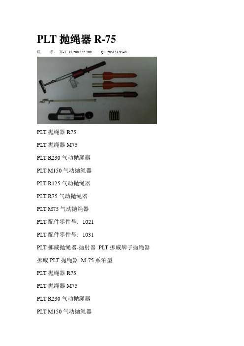
二、PLT® 设备基本款PLT®包括一个基础部件,若干类型抛射体和三种发射管。
1、基础部件这些基础部件部分包含一个内置的高压空气气缸,用于填充高达二百/三百巴(相当于2900/4350磅/平方英寸)的压缩空气。
这些压缩空气足够发射四至六次。
内置的气缸符合潜水设备和空气呼吸器的标准,可以通用这些设备的高压空气压缩机给这个气缸充入洁净干燥的空气。
PLT抛绳器R-75联系:郑-工15 260 822 709 Q 285151 9548PLT抛绳器R75PLT抛绳器M75PLT R230气动抛绳器PLT M150气动抛绳器PLT R125气动抛绳器PLT R75气动抛绳器PLT M75气动抛绳器PLT配件零件号:1021PLT配件零件号:1031PLT挪威抛绳器-抛射器PLT挪威牌子抛绳器挪威PLT抛绳器M-75系泊型PLT抛绳器R75PLT抛绳器M75PLT R230气动抛绳器PLT M150气动抛绳器PLT R125气动抛绳器PLT R75气动抛绳器PLT M75气动抛绳器PLT配件零件号:1021PLT配件零件号:1031PLT挪威抛绳器-抛射器PLT挪威牌子抛绳器挪威PLT抛绳器M-75系泊型DNH扬声器CAS-6T, 6W, 70/100 V olt, weissDNH扬声器CAS-15, 8 Ohm, 15W, eloxal DB-Zulassung DNH扬声器CAS-15, 8 Ohm, 15W, weiss DB-Zulassung DNH扬声器CAS-15T,15W, 70/100 V olt, eloxal DB-Zulassung DNH扬声器CAS-15T, 15W, 70/100 V olt, weiss, DB-Zulassung DNH扬声器CAS-30, 8 Ohm, 30W, eloxalDNH扬声器CAS-30, 8 Ohm, 30W, weissDNH扬声器CAS-30T, 30W, 70/100 V olt, weissDNH扬声器CAS-30T, 30W, 70/100 V olt, eloxalDNH扬声器CAU-4, 20 Ohm, 4WDNH扬声器CAU-4T, 4W, 70/100 V oltDNH扬声器CAP-15W, 8 Ohm, 15W, wei?, IP-55DNH扬声器CAP-15W, 20 Ohm, 15W, wei?, IP-55 DNH扬声器CAP-15WT, 15W, 70/100 V olt, wei?, IP-55 DNH扬声器CAP-15WT, 15W, 70/100 V olt, eloxal, IP-55 DNH扬声器CAR-4, 8 Ohm, 4W, weiss, Montageplatte DNH扬声器CAR-4, 8 Ohm, 4W, eloxal MontageplatteDNH扬声器CAR-4, 20 Ohm, 4W, weiss, Montageplatte DNH扬声器CAR-4, 20 Ohm, 4W, eloxal Montageplatte DNH扬声器CAR-4T, 4W, 100 V olt, wei?, Montageplatte DNH扬声器CAR-4T, 4W, 100 V olt, eloxal, Montageplatte DNH扬声器CAR-6, 8 Ohm, 6W, wei?, Montageplate DNH扬声器CAR-6, 8 Ohm, 6W, eloxal Montageplate DNH扬声器CAR-6, 20 Ohm, 6W, weiss Montageplate DNH扬声器CAR-6, 20 Ohm, 6W, eloxal, Montageplate DNH扬声器CAR-6T, 6W, 100 V olt, weiss Montageplate DNH扬声器CAR-6T, 6W, 100 V olt, eloxal Montageplate DNH扬声器CAR-6F, 6W, 8 Ohm, eloxal oder weissDNH扬声器CAR-6FT, 6W, 100 V olt, wei?DNH扬声器CAR-6FT, 6W, 100 V olt, eloxalDNH扬声器CAP-6F, 6W, 8 Ohm, eloxal oder weiss DNH扬声器CAP-6FT, 6W, 100 V olt, eloxal oder weiss DNH扬声器Prosound-300LT, 30W, 100 V olt, wei? DNH扬声器Prosound-300LT, 30W, 100 V olt, schwarz DNH扬声器Bügel, wei?DNH扬声器Bügel, schwarzDNH扬声器Schwenkfu?, schwarzDNH扬声器Schwenkfu?, wei?DNH扬声器BaldachinDNH扬声器PS-6LT, 6W, 100 V olt, weiss DNH扬声器Bügel, wei?DNH扬声器Bügel, schwarzDNH扬声器Schwenkfu?, schwarzDNH扬声器Schwenkfu?, wei?DNH扬声器BaldachinDNH扬声器DP-10T, 10W, 70/100 V olt, IP-55 DNH扬声器DP-30T, 30W, 70/100 V olt, IP-55 DNH扬声器DPD-10T, 10W, 70/100 V olt, IP-55 DNH扬声器DPD-30T, 30W, 70/100 V olt, IP-55 DNH扬声器Mastbefestigung, V2ADNH扬声器BP-560, 6W, 8 Ohm, ABS, RAL 9010 DNH扬声器BP-560T, 6W, 70/100 V olt, ABS, RAL 9010 DNH扬声器BP-660, 8 Ohm, 6W, ABS, RAL 9010。
PLT抛绳器泉州市双环贸易发展有限公司前身为福建省泉州市博大商贸有限公司,系双环(香港)国际控股集团有限公司设立于大陆的子公司,是一家专业从事油田设备、工程机械、矿山机械、港口机械、能源发电机设备等成套设备供应及零配件批发的进出口公司。
在国外众多著名厂商的大力支持及香港总公司的正确领导下,公司建立了庞大的供需网络,供货速度、产品价格及产品质量,在国内市场占有绝对优势.描述:带有救生抛射头的缆索抛绳器。
可用于小型船舶。
基础部件:基础部件内置一汽缸,可以填充压缩空气200-300巴(2900/4350普西)。
这就足够发射4-6发。
抛射头:装配有4个营救抛射头和一个训练抛射头。
营救抛射头由丙烯腈-丁二烯-苯乙烯塑胶制成,内带铝制管。
营救抛射体配有170米(186码)的尼龙绳,且能够回收并重复使用。
培训抛射头由聚氧化甲烯塑胶制成,并带有橡胶尖端。
本身不带有绳索,但是可配内装120米/5毫米规格绳索的绳盒,训练时候可用。
装载设备:带有手柄,可将安全绳索重新回收进营救抛射头。
只需要简单地将其连接到5-10巴(72-145普西)的压缩空气,绳索就能够很容易地被回收到抛射头内。
技术数据:射程范围最大150米绳索拉力最小2000牛绳索厚度3,2毫米飞行时间大约4秒后坐力最大5400牛内容:1个产品编号1005 带有汽缸的PLT基础部件1个产品编号3303 R-125的发射管2个产品编号3101 R-125的营救抛射头1个产品编号7004 训练抛射头1个产品编号6202 带有120米/5毫米规格的绳索的绳盒1个产品编号3200 装载设备R-1251张用户手册的CD。
National Oilwell Varco(中文译名:国民油井华高)NATIONAL OILWELL VARCO (中文译名:国民油井华高)作为井下工具和设备的世界领军企业,提供具有先进技术、精益制造和可靠质量的井下工具,并提供NOV 再认证及年度保养维修服务。
NOV在80多个国家分布着150 多个作业地点,NOV的全球性的网点分布、无和伦比的井下工具配套和经验丰富的人员配置,使我们能够满足顾客最苛刻的钻井工况需求。
NATIONAL OILWELL VARCO(中文译名:国民油井华高)是起升解决方案的最佳选择。
NOV 为海上工程船、固定及浮式采油的安装、海上支持设施和陆地使用提供专用工程设计、设备、系统及服务。
NOV 提供各种吊车、绞车、锚泊、铺管和敷缆系统、升降和滑移设备以及动态补偿系统。
此外,产品系列还包括FPSO 成套设备及锚泊牵引和供应船(AHTS) 成套设备。
National Oilwell Varco通过质量导向的生命周期管理以及售后备件和服务计划,提供无和伦比的起升解决方案。
钻井工具解决方案National Oilwell Varco提供世界上最全面和最可靠的钻井工具和设备。
我们为能成为唯一一家提供和服务全套井下钻具总成的独立井下工具制造厂商而自豪。
本公司的产品范围包括:钻头钻井马达动力部分扩孔器扩孔工具扶正器震击工具无磁钻井部件电磁随钻测量(MWD)系统钻铤钻井震击器钻井震击器助力器钻杆NOV 提供最广泛最全面的扩孔工具,以经验证的技术满足该行业最复杂、多样和困难的开孔作业要求。
我们的产品包括固定切削刃钻柱工具、双心钻头和同心井下扩孔器。
修井和完井解决方案National Oilwell Varco 制造的Bowen® 打捞工具已有85年以上的历史。
产品包括捕捞工具,打捞冲击工具(如:震击器、助力器、缓冲短节、碎物打捞工具),磨铣和切割工具以及修补工具。
NOV 提供计算机控制的“打捞和钻井震击器定位程序”,确定震击器在钻柱中的最佳位置以使震击的冲击力能量最大化,补偿井眼角度、井眼曲率和摩擦阻力的影响,适用于垂直、定向和水平井眼分析。
USER INSTRUCTIONSSELF RETRACTING LIFELINES WITH LEADING EDGE CAPABILITYComplies with the ANSI Z359.14 standard andIF YOU HAVE ANY QUESTIONS ABOUT THE PROPER USE OF THE EQUIPMENT, SEE YOUR SUPERVISOR, USER INSTRUCTIONS, OR CONTACT WERNER CO. FOR MORE INFORMATION. Werner Co. Fall Protection 724-588-200093 Werner Rd. 888-523-3371 toll freeGENERAL SAFETY INFORMATIONThese User Instructions are not to be removed except by the user of this equipment. Current User Instructions must always be available to the user.USE INSTRUCTIONS AND LIMITATIONSI MPORTANTBefore use, the user must read and understand these User Instructions. Keep these User Instructions for reference.P URPOSESelf-Retracting Lifelines with Leading Edge capabilities are designed to be used as part of a complete personal fall arrest system.U SE I NSTRUCTIONS1. Failure to follow all instructions and limitations on the use of SRL-LE may result in seriouspersonal injury or death.2. Before using a personal fall arrest system, employees must be trained in accordance with therequirements of OSHA 29 CFR 1910.30 and 1926.503 in the safe use of the system and its3. Personal fall arrest and rescue systems, including the SRL-LE, must be inspected prior to eachuse for wear, damage, and other deterioration. Defective components must be immediatelyremoved from service in accordance with the requirements of OSHA 29 CFR 1910.140 and1926.502.4. The complete fall arrest system must be planned (including all components, calculating fallclearance, and swing fall) before using.5. Users must have a rescue plan, and the means at hand to implement it, that provides forthe prompt rescue of the user in the event of a fall, or assures that the user is able to rescuethemselves. A fall over an edge may require special rescue measures.6. Store the SRL-LE in a cool, dry, clean environment, out of direct sunlight, when not in use.7. After a fall occurs on the system, immediately remove from service until a “competent person”can make the determination for reuse or disposal.U SE L IMITATIONS1. CAP ACITY: SRL-LE’s used in leading edge applications are designed for users with a capacity(including clothing, tools, etc.) up to 310 lb (141 kg) total working weight. The SRL-LE used in overhead applications has a capacity (including clothing, tools, etc.) up to 400 lb (181 kg) total working weight.2. MATERIALS: The lifeline of the SRL-LE is 7x19 3⁄16 inch galvanized steel wire rope.3. CORROSION: Do not leave SRL-LE’s in environments where corrosion of metal parts couldtake place as a result of vapors from organic materials. Use near seawater or other corrosive environments may require more frequent inspections to ensure corrosion damage is not affecting the performance of the product.4. CHEMICAL HAZARDS: Solutions containing acids, alkali, or other caustic chemicals, especiallyat elevated temperatures, may cause damage to the SRL-LE’s. When working with suchchemicals, frequent inspection of this equipment must be performed. Contact Werner Co. with any questions concerning the use of the SRL-LE around chemical hazards.5. EXTREME TEMPERATURE: SRL-LE’s are designed to be used in temperatures ranging from-40°F to +130°F (-40°C to +54°C). Protection should be provided for SRL-LE’s when used near welding, metal cutting or similar activities. Contact Werner Co. with any questions concerning high temperature environments.6. ELECTRICAL HAZARDS: Use extreme caution when working near high voltage power lines dueto the possibility of electric current fl owing through the SRL-LE or connecting components.7. HEALTH: Minors, pregnant women and anyone with a history of either back or neck problemsshould not use this equipment.8. RESCUE: In the event of a fall over the edge, special rescue measures may be required.9. TRAINING: Do not use SRL-LE’s without proper training from a “competent person” as defi ned byOSHA 29 CFR 1910.140(b) and 1926.32(f).10. REP AIRS: Only Werner Co., or persons or entities authorized in writing by Werner Co., maymake repairs or alterations to the equipment.ANCHORAGE REQUIREMENTSA NCHORAGESAll anchorages to which the SRL-LE attaches must meet the requirements of ANSI Z359.2 and OSHA 29 CFR 1910 and 1926.OSHA states:Anchorages used for attachment of personal fall arrest equipment shall be independent of any anchorage being used to support or suspend platforms and capable of supporting at least5,000 pounds (22.2 kN) per employee attached, or shall be designed, installed, and used as part of a complete personal fall arrest system which maintains a safety factor of at least two; and under the supervision of a qualifi ed person.C OMPATIBLE C ONNECTIONSI NCOMPATIBLE CANSI Z359.2 states that anchorages selected for fall arrest systems must have a strength capable of sustaining static loads, applied in all permitted directions by the system:A) no less than 5,000 pounds (22.2 kN) for non-certifi ed anchorages; or B) at least two times the maximum arresting force for certifi ed anchorages;C) according to ANSI Z359.6, Specifi cations and Design Requirements for Active FallProtection Systems.When more than one personal fall arrest system is attached to the anchorage, the strength in (A) or (B) must be multiplied by the number of personal fall arrest systems attached to the anchorage.CONNECTION REQUIREMENTS C OMPATIBILITY L IMITATIONSAll connecting subsystems must only be coupled to compatible connectors. OSHA 29 CFR 1910.140 and 1926.502 prohibit snap hooks from being engaged to certain objects unless two requirements are met: snap hook must be a locking type and must be “designed for” making such a connection. Under OSHA “designed for” means that the manufacturer of the snap hook specifi cally designed the snap hook to be used to connect to the equipment in question.The following connections must be avoided because they can result in rollout* when a non-locking snap hook is used:• Direct connection of a snap hook to horizontal lifeline.• Two (or more) snap hooks connected to one D-ring.• Two snap hooks connected to each other.• A snap hook connected back on its integral lanyard.• A snap hook connected to a webbing loop or webbing lanyard.•Improper dimensions of the D-ring, rebar, or other connection point in relation to the snap hook dimensions that would allow the snap hook keeper to be depressed by a turning motion of the snap hook.*Rollout: A process by which a snap hook or carabiner unintentionally disengages from anotherconnector or object to which it is coupled.NO!CLEARANCE REQUIREMENTSC LEARANCE R EQUIREMENT WITH O FFSET AND S ETBACK D ISTANCER410030LEFOR L EADING E DGE A PPLICATIONS FOR R410020LE ANDE XAMPLE: With the SRL-LE anchor set back 10 feet from the edge, the user can work up to 8 feet(2.4m) offset along the leading edge. The required clearance is 19.8 feet (6.0 m) from the working level to the nearest obstruction below.The required clearance includes; Free Fall and Swing Fall Distance, Harness Stretch, Deceleration Distance and Safety Factor.C LEARANCE R EQUIREMENT WITH O FFSET AND S ETBACK D ISTANCER410065LEFOR L EADING E DGE A PPLICATIONS FORE XAMPLE: With the SRL-LE anchor set back 10 feet from the edge, the user can work up to 8 feet(2.4m) offset along the leading edge. The required clearance is 20.3 feet (6.2 m) from the working level to the nearest obstruction below.The required clearance includes; Free Fall and Swing Fall Distance, Harness Stretch, Deceleration Distance and Safety Factor.O FFSET C LEARANCE R EQUIREMENTS FOR R410020LE AND R410030LEFOR NON LEADING EDGE APPLICATIONSE XAMPLE: With the R410020LE or R410030LE anchored 4 feet above the users D-ring and the user works 2 feet away (offset) from directly overhead (centerline), the required clearance is 6 feet (1.8 m) from the working level to the nearest obstruction below.The required clearance includes; Free Fall and Swing Fall Distance, Harness Stretch, Deceleration Distance and Safety Factor.D-ringHeightAboveD-ringBelowD-ring(0.3 m)(0 m)(0.3 m)(0.6 m)(0.9 m)(1.2 m)(1.5 m)(1.5 m)(1.2 m)(0.9 m)(0.6 m)3 ft(0.9 m)2 ft(0.6 m)1 ft(0.3 m)0 ft(0 m)-1 ft(-0.6 m)-2 ft(-0.6 m)-3 ft(-0.9 m)-4 ft(-1.2 m)-5 ft(-1.5 m)4 ft(1.2 m)5 ft(1.5 m)(0.3 m)0 ft(1.5 m)5 ft(1.5 m)4 ft(1.2 m)3 ft(0.9 m)2 ft3 ft(0.9 m)2 ft(0.6 m)1 ft(0.3 m)0 ft(0 m)-1 ft(-0.6 m)-2 ft(-0.6 m)-3 ft(-0.9 m)-4 ft(-1.2 m)-5 ft(-1.5 m)4 ft(1.2 m)5 ft(1.5 m)6)m5 ft(1.5 m)7f t(2.1m)9ft(2.7m)11ft(3.4m)13ft(4.m)15ft(4.6m)17ft(5.2m)19ft(5.8m)21f t(6.4m) 2ft(6.1m22ft(6.7m))18ft(5.5m)16ft(4.9m)14ft(4.3)m12ft(3.7)ft(3.m1ft(2.4m)8ft(1.8m)1 ft(0 m)1 ft(0.3 m)2 ft(0.6 m)3 ft(0.9 m)4 ft(1.2 m)5 ft5 m)5 f(1.5(0.6 m)O FFSET C LEARANCE R EQUIREMENTS FOR R410065LE FOR NON LEADING EDGE APPLICATIONS(0.3 m)(0 m)(0.3 m)(0.6 m)(0.9 m)(1.2 m)(1.5 m)(1.5 m)(1.2 m)(0.9 m)(0.6 m)3 ft (0.9 m)2 ft (0.6 m)1 ft (0.3 m)0 ft (0 m)-1 ft (-0.6 m)-2 ft (-0.6 m)-3 ft (-0.9 m)-4 ft (-1.2 m)-5 ft (-1.5 m)4 ft (1.2 m)5 ft (1.5 m) 1 ft (0.3 m)0 ft (0 m)1 ft (0.3 m)2 ft (0.6 m)3 ft (0.9 m)4 ft(1.2 m)5 ft (1.5 m) 5 ft (1.5 m)4 ft (1.2 m)3 ft (0.9 m)2 ft (0.6 m)3 ft (0.9 m)2 ft (0.6 m)1 ft (0.3 m)0 ft (0 m)-1 ft (-0.6 m)-2 ft (-0.6 m)-3 ft (-0.9 m)-4 ft (-1.2 m)-5 ft (-1.5 m)4 ft (1.2 m)5 ft (1.5 m)174116 ft (1.8 m)8 f t (2.4 m )10 f t(3.0m )12 ft (3.7 m)14 f t (4.3m)16f t (4.9m)18f t (5.5m )20f t(6.1m )22f t (6.7m)1 f 582 f t (6.4 1)m 9t (.m )7 f t (5 .2m )5 f t (4.6 1m )3f t (4.0 m )1 f t (3. m1)9 f t (2. m)7 f t(2. m)f t (7.0 m 325 m)5 f (1.5)D-ring HeightAbove D-ringBelow D-ringE XAMPLE : With the R410065LE anchored 4 feet above the users D-ring and the user works 2 feet away (offset) from directly overhead (centerline), the required clearance is 7 feet (2.1 m) from the working level to the nearest obstruction below.The required clearance includes; Free Fall and Swing Fall Distance, Harness Stretch, Deceleration Distance and Safety Factor.H ORIZONTAL S YSTEMSApplications where the SRL-LE is used horizontally or with a horizontal system, the SRL-LE and horizontal system components must be compatible. Both the horizontal and vertical distances are required for clearance calculations. Horizontal systems must be designed and installed under the supervision of a qualifi ed person.These units are suitable for use with horizontal lifelines.PERFORMANCEThe Werner Co. SRL-LE was successfully tested for horizontal use and falls over a steel edge without burrs, concrete and b-decking and as a result, these devises may be used in applications where a fall may occur over similar edges.L EADING E DGE U SE A PPLICATIONS FOR R410020LE AND R410030LEC LEARANCE C ALCULATIONSSRD-LE(1.8 m)(8 kN)(4 kN)(0.6 m)(5.1 m)(59 - 141 kg)OSHA 29 CFR 1910.140/1926.5026 ft (1.8 m)1800 lbs (8 kN)N/A2 ft (0.6 m)17 ft (5.1 m)310 lbs (141 kg)L EADING E DGE U SE A PPLICATIONS FOR R410065LEO VERHEAD U SE N ON L EADING E DGE A PPLICATIONS FOR R410020LE AND R410030LEVERHEAD SE ON EADING DGE PPLICATIONS FOR OPERATION B EFORE E ACH U SEThe user must read and understand these user instructions, as well as the user instructions for every component and subsystem of the personal fall arrest system.Users must have a rescue plan, and the means to implement it, that provides for the prompt rescue of employees in the event of a fall or assures that employees are able to rescue themselves.Check the operation by pulling smoothly on the lifeline, then pulling sharply on the lifeline to engage the locking mechanism.SRL-LE’s must be inspected prior to each use. See INSPECTION.C ONNECTIONAttach the housing connector of the SRL-LE to the anchorage or anchorage connector. The opposing end is connected to the dorsal D-ring of the full body harness.SRD-LE(1.8 m)(8 kN)(4 kN)(0.6 m)(5.4 m)(59 - 141 kg)OSHA 29 CFR 1910.140/1926.5026 ft (1.8 m)1800 lbs (8 kN)N/A2 ft (0.6 m)17.5 ft (5.4 m)310 lbs (141 kg)SRD Class A (610 mm)(0.6 m)(8 kN)(6 kN)(59 - 141 kg)OSHA 29 CFR 1910.140/1926.50242 in (1067 mm)2 ft (0.6 m)1800 lbs (8 kN)N/A400 lbs (181 kg)SRD Class B (812 mm)(0.6 m)(8 kN)(4 kN)(59 - 141 kg)OSHA 29 CFR 1910.140/1926.50242 in (1067 mm)2 ft (0.6 m)1800 lbs (8 kN)N/A400 lbs (181 kg)INSPECTIONF REQUENCYAll components of SRL-LE’s must be inspected prior to each use, and annually by an OSHA defi ned “competent person” other than the user. Local, state, governmental and jurisdictional agencies governing occupational safety may require the user to conduct more frequent or mandatory inspections.C RITERIAAll components of the SRL-LE must be inspected.All markings must be legible and attached to the product.Housing must be free from cracks, distortion or any other damage.White web visible outside the shock pack is the fall indicator that the SRL-LE has been subjected to the forces of arresting a fall.Reserve cable is wrapped in colored tape. Remove from service if colored tape has exited the unit. Check the operation of the unit by pulling smoothly on the lifeline, then pulling sharply on the lifeline to engage the locking mechanism. Unit must not slip when locked.Cable must be inspected for kinks, broken strands, corrosion, abrasion, or other signs of wear and/or damage. Swaged terminations must be secure with the thimble tight and no visible damage.All equipment must be free of corrosion, chemical attack, alteration, excessive heating or wear.All snap hooks and carabiners on product must be able to self-close and lock. All hardware must be free of cracks, sharp edges, deformation, corrosion, or any evidence of defect.All components of the fall arrest system must be inspected. See User Instructions supplied with each product.CLEANING, MAINTENANCE AND STORAGEC LEANINGCleaning and maintenance may be performed by the user. The SRL-LE may be wiped down with a mild detergent and clean water solution, and rinsed with a dampened clean cloth to remove detergent. The hardware can also be wiped down to remove grease or dirt with a clean dry cloth.M AINTENANCESRL-LE’s requiring maintenance must be tagged “unusable” and removed from service. Do not use any SRL-LE that requires maintenance. Cleaning and maintenance may be performed by the user.Snap hooks may require periodic lubrication. Do not apply oil, grease, or other contaminants on the webbing or cable. Use a dry lubricant that has proper resistance to temperature extremes, moisture, and corrosion. Do not over-lubricate.S TORAGESRL-LE’s should be stored in a cool, dry place out of direct sunlight when not in use. Do not store where damage from environmental factors such as heat, light, excessive moisture, oil, chemicals and their vapors, or other degrading elements may be present.Do not store damaged equipment or equipment in need of maintenance in the same area as product approved for use.Equipment that has been stored for an extended period must be inspected as defi ned in these User Instructions prior to use.Overhead Use Non Leading Edge ApplicaƟons11Werner Co. Fall Protection93 Werner Rd. Greenville, P A 16125724-588-2000 • 888-523-3371 toll free • 888-456-8458 fax PN115849-01 ©2018 Werner Co. Rev B 6/18。
PLT R125营救型
描述:
带有救生抛射头的缆索抛绳器。
可用于小型船舶。
基础部件:
基础部件内置一汽缸,可以填充压缩空气200-300巴(2900/4350普西)。
这就足够发射4-6发。
抛射头:
装配有4个营救抛射头和一个训练抛射头。
营救抛射头由丙烯腈-丁二烯-苯乙烯塑胶制成,内带铝制管。
营救抛射体配有170米(186码)的尼龙绳,且能够回收并重复使用。
培训抛射头由聚氧化甲烯塑胶制成,并带有橡胶尖端。
本身不带有绳索,但是可配内装120米/5毫米规格绳索的绳盒,训练时候可用。
装载设备:
带有手柄,可将安全绳索重新回收进营救抛射头。
只需要简单地将其连接到5-10巴(72-145普西)的压缩空气,绳索就能够很容易地被回收到抛射头内。
技术数据:
射程范围最大150米
绳索拉力最小2000牛
绳索厚度3,2毫米
飞行时间大约4秒
后坐力最大5400牛
内容:
1个产品编号1005 带有汽缸的PLT基础部件
1个产品编号3303 R-125的发射管
2个产品编号3101 R-125的营救抛射头
1个产品编号7004 训练抛射头
1个产品编号6202 带有120米/5毫米规格的绳索的绳盒
1个产品编号3200 装载设备R-125
1张用户手册的CD。