【US20190372529A1】LowNoiseAmplifierCircuitforaTherm
- 格式:pdf
- 大小:1.32 MB
- 文档页数:25

Optimum Design for a Low Noise Amplifier in S-Band 佚名【期刊名称】《电子科技学刊》【年(卷),期】2007(005)003【摘要】An optimum design of a low noise amplifier (LNA) in S-band working at 2-4 GHz is described. Choosing FHC40LG high electronic mobility transistor (HEMT), the noise figure of the designed amplifier simulated by Microwave Office is no more than 1.5 dB, meanwhile the gain is no less than 20 dB in the given bandwidth. The simulated results agree with the performance of the transistor itself well in consideration of its own minimum noise figure (0.3 dB) and associated gain (15.5 dB). Simultaneously, the stability factor of the designed amplifier is no less than 1 in the given bandwidth.【总页数】4页(P234-237)【正文语种】中文【中图分类】TN91【相关文献】1.Design of 5 GHz low noise amplifi er with HBM SiGe 0 .3μm BiCMOS process [J], Xu Jian;Xi Chen;Li Ma;Yang Zhou;Wang Zhigong2.Design and analysis on four stage SiGe HBT low noise amplifier [J], Jing kai;Zhuang Yiqi;Li Zhenrong;Lin Zhiyu3.Analysis, Design and Implementation of SiGe Wideband Dual-Feedback Low Noise Amplifier [J], 张为;宋博;付军;王玉东;崔杰;李高庆;张伟;刘志弘4.DESIGN AND ANALYSIS OF INTEGRATED OPERATIONAL AMPLIFIERXD1531 WITH LOW NOISE AT LOW FREQUENCIES [J], 郝跃;姚立真5.An X-Band Low Noise Amplifier Design for Marine Navigation Radars [J], Christina Lessi;Evangelia Karagianni因版权原因,仅展示原文概要,查看原文内容请购买。
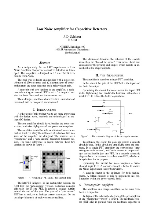
Low Noise Amplifier for Capacitive Detectors.J. D. SchipperR KluitNIKHEF, Kruislaan 4091098SJ Amsterdam, Netherlandsjds@nikhef.nlAbstractAs a design study for the LHC experiments a 'Low Noise Amplifier Shaper' for capacitive detectors is devel-oped. This amplifier is designed in 0.6 um CMOS tech-nology from AMS.The goal was to design an amplifier with a noise con-tribution of 250 electrons, and 12 electrons per pF contri-bution from the input capacitor and a relative high gain.A test chip with two versions of the amplifier, a 'radia-tion tolerant' (gate-around FET's) and a 'rectangular' ver-sion has been fabricated and is now under test.These designs, and there characteristics, simulated and measured, will be compared and discussed.I.I NTRODUCTIONA other goal of this project was to get more experience with the design- tools, methods and technologies in ana-logue IC design.The pre-amplifier should have, besides the noise con-straints, a relative high gain and low power consumption.The amplifier should be able to withstand a certain ra-diation level. To study the influence of radiation, two ver-sions of the amplifier are designed. The versions are a ‘rectangular’ and a ‘gate around’ (radiation tolerant) ver-sion. The basic difference in layout between these two versions is shown in figure 1.gate leak agepathFigure 1: A ‘rectangular’ FET and a ‘gate-around’ FETThe left FET in figure 1 is the 'rectangular' version, the right FET the ‘gate-around’ version. Radiation damages especially the N-type FET. It causes a leakage current around the end of the gate. The gate of a ‘gate-around’FET has no end, so no leakage current can occur. On the test chip 4 channels of each version are realized.This document describes the behavior of the circuits when they are “biased for speed”. This means short time constants for the preamp and shaper, which results in un-dershoot at the shaper outputs.II.T HE P REAMPLIFIERThe amplifier is based on a single FET amplifier.In this circuit the gate of the FET M0 is the input and the drain the output.Optimising the circuit for noise makes the input FET wide. Optimising for bandwidth however subscribes a small FET, to reduce the Miller capacitance.M0M1M16M2M13M28M30C0Inpre_bias1pre_bias3VSSVSSGNDVSSVSSVDDGNDVSSpre_bias2pre_resVDDoutputFigure 2:The schematic diagram of the rectangular version.To optimise the circuit for gain and power a cascode circuit is used. In this circuit the amplifying steps are sepa-rated. In a single FET amplifier the conversions ‘input voltage to drain current’, and ‘drain current to output volt-age’ are realized in just one FET. In a cascode schematic diagram both conversions have their own FET, which can be optimized for its purpose.Optimising the circuit for noise requires a wide-channel input FET. A narrow channel is better to reduce the Miller capacitance (larger bandwidth).A cascode circuit is the optimum for both require-ments. A folded cascode is used to implement this con-figuration within the power supply limits.A.‘Rectangular’ amplifierThe amplifier is a charge amplifier, so the main feed-back is a capacitor.In figure 2 the schematic diagram of the pre-amplifier in the ‘rectangular version’ is drawn. The feedback resis-tor (FET M2) in parallel with the feedback capacitor isrequired to control the DC operating point of the amplifier.The output level of the amplifier will stabilize without any precautions on about –1 Volt. This would give an asym-metrical dynamic range. To make this symmetrical, the output level should stabilize at 0 Volt. To realize this, one gate-source voltage is subtracted from the output of the amplifier.The resistor is needed for DC and low frequency feed-back. The resistance is adjustable by an external voltage (pre_res) to control the trailing edge of the amplifier sig-nal. To operate the circuit, 3 DC bias currents must be applied:1. input FET bias (pre_bias_1),2. cascode FET bias (pre_bias_2),3. subtraction network bias (pre_bias_3).B. 'Gate around' amplifierM0M1putpre_bias1VDDVDDpre_respre_bias2VSS VSSVSSM16GNDM13VDD M2pre_bias3C0VDDVDDVDDoutput VDDFigure 3: Schematic diagram of the gate around version.The circuit is quite similar to the previous version. The major change is due to the fact that we cannot use a N-FET as a feedback (in ‘gate around ’ it is not possible to make a FET longer then wide), so a P-FET is used instead.The operating voltage on the gate of the feedback FET,when changed from the N-type to the P-type, is below –2Volt, which is unacceptable. To get this voltage between the power supplies we have to change two things (see fig-ure 2):1. Connect the source of M0 to VDD (+2 Volt). Thislifts the gate of FET M0 to +1 Volt.2. The level subtraction at the output must becomelevel adder. This makes the output again about 0Volt.III. T HE SHAPERThis circuit has the same configuration as the circuit of the pre-amplifier. The differences between the circuits are the input capacitor and the dimensions of the used compo-nents.A. 'Rectangular' shaperThe shaper is an active band-pass filter. The compo-nents that control the bandwidth of this filter are the input capacitor, the feedback capacitor and the feedback resis-tor. The feedback capacitor and resistor determine the high roll off point, while the input capacitor and the feedback resistor control the low roll off point.inputC6M33GNDVDDsha_bias1M39VSSsha_resC10VSSM38sha_bias2M31VDDM37VSSGNDsha_bias3outputM34VSSM35VSSFigure 4: The schematic diagram of the shaper, ‘normal ’ ver-sion.B. 'Gate around' shaper.The differences between the ‘rectangular ’ and the ‘gatearound ’ versions are similar as with the pre-amplifier ver-sions.inputC6sha_bias1VSS VSSM39M33VDDVDDsha_bias2sha_resVDDM38VDDC10M31M37VSSGNDsha_bias3VDDVDDVDDoutputFigure 5: The schematic diagram of the shaper, 'Gate Around'version.IV. T HE OUTPUT BUFFERThe shaper signals are measured in the test set-up with an oscilloscope. The oscilloscope has high impedance in-puts (1M •), with a capacitive load of 10 pF. Because the shaper output is does not have the capability to drive a capacitive load, the signals need to be buffered.inputbiasoutputVDDVSSVSSVSSVSSVSSVSSVDDVDDVDDFigure 6: The schematic diagram of the output buffer.The buffer circuit is equal for both versions. The cir-cuit consists of a differential amplifier with a high current output stage. The differential amplifier is designed to cre-ate a buffer with a gain of 1.V. T HE CIRCUIT SIMULATIONSThe schematic diagrams above are the result of exten-sive list of simulations, in which we looked for the best combination of parameters.During the simulations, and also later during the meas-urement, we used an input charge of 1 MIP, which corre-sponds to ~12000 electrons in 150µm silicon. The charge is injected via a capacitor of 1.5pF. The applied voltage step is:mVp C Q n C Q U el el 28,151106021,11200019b b bIn figure 7 shows the simulated step response of the amplifier. The upper line is the response of the ‘rectangu-lar ’ version and the lower line of the ‘gate around ’ ver-sion. A capacitor of 20pF was connected at the input to simulate the detector capacitance.The gain of both versions differs due to the differences in the point of operation of the input FET (M0) in both versions. The source is connected to GND or to VDD.Figure 7: The step response of the circuits.This simulation is done with a relatively fast settling time for the pre-amplifier. This results in a fast falling edge of the output pulse on the pre-amplifier and 60%overshoot after the shaper. In case the amplifier is biased for a time constant, much longer than of the shaper, no undershoot will occur.The circuit is optimised for gain, speed and noise. For figure 7 a detector capacitance of 20pF was used.Figure 8 and 9 show the dependency of the gain and S/N in relation with the input capacitance (detector) of the amplifier and shaper.Also simulated is the dynamic range of the circuits.The result is plotted in figure 10 and 11, for an input range of –10 to +10 MIP.O utpu t (m V )C ap acitor (pF )0102030405060708090100051015202530Gate aroundRectangularFigure 8: Gain plot, simulatedN o ise (electro n s)C ap acitor (pF )05001000150020002500300051015202530G a te a r o u n d R e c ta n g u la rFigure 9: Noise plot, simulated.O utp u t (m V )In p ut (M IP )-400-300-200-100100200300400500-10-8-6-4-20246810Rectangular reference errorFigure 10: The dynamic range of the ‘rectangular ’ version.O utp u t (m V )In p ut (M IP )-800-600-400-200200400600800-10-8-6-4-20246810Gate Around reference errorFigure 11: The dynamic range of the ‘gate around ’ version.All simulations are done with the bias settings from ta-ble 1. In the measurements the same bias settings are used,to allow a good comparison between both results.Table 1: Settings used with the simulationCircuitSignalnetrect GA Pre-amplifierIbias input FET Ipre_bias1500500uA Ibias cascode FET Ipre_bias2-10-50uA Ibias level shifter Ipre_bias21-1uA V feedback resistor Vpre_res 500-500mV ShaperIbias input FET Isha_bias11020uA Ibias cascode FET Isha_bias2-2-4uA Ibias level shifter Isha_bias3500-1nA V feedback resistor Vsha_res500-500mV Vdd +2V Vss-2VVI. M EASUREMENTSThree measurements are made with the chip, gain, dy-namic range and noise.For the gain test the set-up in figure 12 is used. With a digital oscilloscope a large number of measurements are gathered and the mean of peak values gives the size of the output signal for 1 MIP.D.U.T.-20 d B -20 d B -20 d BFigure 12: The test set-up.O u tp ut (m V )C apacito r (p F)10203040506051015202530G ate ar ou n d Rectan gu larFigure 13: Gain plot, measured.O utp u t (m V )In p ut (M IP )-250-200-150-100-5050100150200250-10-8-6-4-2246810Rectangular reference errorFigure 14: The measured dynamic range, ‘rectangular ’ version.Output (mV)Input (MIP)-300-200-100100200300-10-8-6-4-2246810Gate AroundreferenceerrorFigure 15: The measured dynamic range, ‘gate around ’ version.In the figures 15 and 16 the plots of the measured out-put signal is plotted over –10 to +10 MIP. Due to the low gain bias setting, the full dynamic output range is not reached.For the noise test the input of the amplifier is left open,besides the detector capacitance. The oscilloscope calcu-lates the RMS value of the AC signal at the output (Fig-ure: 12). Similar to the simulations, the test is done with 7values for the detector capacitance.n o ise (ele ctro n s)C a p ac ito r (p F )050010001500200025003000350040004500051015202530G ate arou n d R ectan g u larFigure 16: The noise plot, measured.Table 2: Comparing simulation and tests.M easuredSim ulationD elta20 20 (pF)(pF)G ate around:35 50 0.7 N oise [mV ]7.2 7.3 1.0 N oise [el] 2469 1741 1.4 S/N4.9 6.9 1.4Recta ngular:20 28 0.7 N oise [mV ]4.6 4.6 1.0 N oise [el]2760 1956 1.4 S/N4.36.11.4O utput 1M IP [mV ]O utput 1M IP [mV ]The measured bias currents and voltages show less then 8% deviation from the expected simulated values.Other differences are:Rectangular version:N The actual gain is less than simulated.N The value of the noise is the same, but due to lower gain is the S/N ratio lower than expected.N The linearity is acceptable between +/- 4MIP. Outside that the deviation goes up to 10%.Gate around version:N The actual gain is less than simulated.N The value of the noise is the same, but due to lower gain is the S/N ratio lower than expected.N The non-linearity shows the same behaviour, but the deviation is worse.1.C ONCLUSIONSSince the preamp shows a slower 1st slope, the shaper output is less then expected. This also results in a worse S/N ratio than expected.The feedback FET’s has been designed to short, this in combination with a small Cfb (~25fF) results in an insta-ble operation point for the rectangular version for longer (>1us) time constants. These small components could be the cause of the differences between simulation and meas-urement.In case the circuit is biased as presented (with short time constants) there is no instability but the S/N ratio is poor.Measurements show a poor linearity, this also is a drawback of a short feedback transistor since the linear range is rather small.VII.W ORK TO BE DONEFor better understanding of the differences between simulation and measurements, more measurements will be done. Longer time constant of the preamplifier will be used to investigate the noise contributions. First measure-ments show a drastic increase in S/N at peaking times > 50ns, at a gain of more than 120mV/12000e.In order to study the influence of radiation on both ver-sions, a number of chips will be irradiated and compared with the not irradiated devices.VIII.R EFERENCES1. A CMOS Mixed-Signal Readout Chip for the Microstrip Detectors of HERA-B. W. Fallot-Burghardt.2.Low-Noise Wide-Band Amplifiers in Bipolar andCMOS Technologies. Zhong Yuan Chang, W. M. C.Sansen.。

专利名称:MICROWAVE LOW NOISE AMPLIFIER 发明人:YOSHIMASU TOSHIHIKO申请号:JP28808890申请日:19901024公开号:JPH04160808A公开日:19920604专利内容由知识产权出版社提供摘要:PURPOSE:To minimize an NF of a FET and to decrease an input side VSVW simultaneously by connecting a connection part between a source electrode and a capacitor to ground via an inductor or a transmission line. CONSTITUTION:An input side reflection coefficient (GAMMANopt) minimizing a noise figure NF of a FET and an input side reflection coefficient (GAMMAS) are made close to each other by the action of a capacitor connected between a drain and a source of the FET and a feedback component of the FET. In this case, when a capacitor Cds is not added, the coefficients GAMMANot, GAMMAS differ from each other largely, they are made close to each other attended with the increase on the capacitor Cds, and when the Cds increases, they are again parted. Thus, the optimum Cds making the coefficients GAMMAS, GAMMANot closest is in existence. Thus, the NF of the FET and the input VSWR are made small simultaneously.申请人:SHARP CORP更多信息请下载全文后查看。

专利名称:LOW NOISE AMPLIFIERS WITHTRANSFORMER-BASED SIGNAL SPLITTINGFOR CARRIER AGGREGATION发明人:DAVIERWALLA, Anosh Bomi,TASIC,Aleksandar Miodrag申请号:US2013/042748申请日:20130524公开号:WO2013/177567A1公开日:20131128专利内容由知识产权出版社提供专利附图:摘要:Low noise amplifiers (LNAs) supporting carrier aggregation are disclosed. In anexemplary design, an apparatus (e.g., a wireless device, an integrated circuit, etc.) includes an amplifier circuit, a transformer, and a plurality of downconverters. The amplifier circuit receives and amplifies an input radio frequency (RF) signal and provides an amplified RF signal. The input RF signal includes transmissions sent on multiple carriers at different frequencies to a wireless device. The transformer includes a primary coil coupled to the amplifier circuit and a plurality of secondary coils providing a plurality of output RF signals. The plurality of downconverters downconvert the plurality of output RF signals with a plurality of local oscillator (LO) signals at different frequencies. Each downconverter includes a pair of mixers that receives one output RF signal and one LO signal and provides inphase and quadrature downconverted signals for one set of carriers being received.申请人:QUALCOMM INCORPORATED地址:92121 US国籍:US代理人:MOBARHAN, Ramin更多信息请下载全文后查看。

专利名称:AMPLIFIER WITH LOW NOISE 发明人:HANDA KAZUNORI申请号:JP27470487申请日:19871031公开号:JPH01119101A公开日:19890511专利内容由知识产权出版社提供摘要:PURPOSE:To prevent mechanical distortion and deterioration in a high frequency characteristic from being generated by providing a flange with choke structure on the input terminal of a waveguide. CONSTITUTION:The input terminal I of an amplifier main body 1 is formed with an input waveguide 4, and a choke type flange 5 is provided on the tip part of the input waveguide 4. The choke type flange 5 is structured so that it can be short-circuited equivalently to the plane of the waveguide without being brought into contact with it. And a signal inputted from the input terminal I is introduced to the amplifier main body 1 via the choke type flange 5. Here, since a cavity 5c is formed between a choke part 5a and a cover part 5b, the input waveguide 4 is not brought into contact with an external conductor, thereby, the mechanical play of the amplifier main body 1 can be secured. In such a way, it is possible to prevent the mechanical distortion of the input terminal I and the deterioration in the high frequency characteristic from being generated.申请人:NEC CORP更多信息请下载全文后查看。
专利名称:Low noise amplifiers for carrier aggregation发明人:Aleksandar Miodrag Tasic,Anosh BomiDavierwalla申请号:US13590423申请日:20120821公开号:US09154356B2公开日:20151006专利内容由知识产权出版社提供专利附图:摘要:Low noise amplifiers (LNAs) supporting carrier aggregation are disclosed. In an exemplary design, an apparatus includes first and second amplifier stages, e.g., for a carrier aggregation (CA) LNA or a multiple-input multiple-output (MIMO) LNA. The firstamplifier stage receives and amplifies an input radio frequency (RF) signal and provides a first output RF signal to a first load circuit when the first amplifier stage is enabled. The input RF signal includes transmissions sent on multiple carriers at different frequencies to a wireless device. The second amplifier stage receives and amplifies the input RF signal and provides a second output RF signal to a second load circuit when the second amplifier stage is enabled. Each amplifier stage may include a gain transistor coupled to a cascode transistor.申请人:Aleksandar Miodrag Tasic,Anosh Bomi Davierwalla地址:San Diego CA US,San Diego CA US国籍:US,US代理人:Ramin Mobarhan更多信息请下载全文后查看。
专利名称:LOW NOISE AMPLIFIER AND DIFFERENTIALAMPLIFIER发明人:Kouichiro Yamaguchi申请号:US12183857申请日:20080731公开号:US20090108937A1公开日:20090430专利内容由知识产权出版社提供专利附图:摘要:In a double-loop negative feedback low noise amplifier having double negative feedback paths by a feedback transformer and a feedback resistor added to a cascode amplifier comprising transistors and a resistor, a phase compensation circuit comprising acapacitor and a resistor is added between the output terminal of the double-loop negative feedback low noise amplifier and the input terminal of the cascode amplifier, i.e., the input terminal of the input transistor, and a phase compensation circuit comprising a capacitor and a resistor is added to the upper-stage transistor of the cascode amplifier, i.e., the input terminal of the upper-stage transistor. Those phase compensation circuits enable a low noise negative feedback amplifier which maintains a high feedback loop gain to a high frequency band, has a wider bandwidth than a conventional one, and has a high dynamic range.申请人:Kouichiro Yamaguchi地址:Tokyo JP国籍:JP更多信息请下载全文后查看。
专利名称:LOW NOISE AMPLIFIER AND IMAGING ELEMENT USING SAME发明人:FOWLER, Boyd申请号:US2003009160申请日:20030324公开号:WO03/084055P1公开日:20031009专利内容由知识产权出版社提供摘要:An imaging element (50) that includes a photodiode (21) and an amplifier for integrating photocurrent from the photodiode. The amplifier includes an input follower (51), a level shifter (52), and an output amplifier (53). The level shifter (52) provides DC isolation between the follower output and the output amplifier (53). The input follower (51) includes an input transistor (62) connected to the photodiode (21), and the output amplifier (53) has an input transistor (66) connected to the level shifter (52). The sizes of these transistors are chosen such that the area of the input transistor (62) in the input follower (51) is less that the area of the input transistor (66) in the output amplifier (53). The input follower (51) preferably utilizes PMOS transistors.申请人:AGILENT TECHNOLOGIES, INC.地址:IPA Legal Dept. MS DL 429 815 SW 14th Street Loveland, CO 80537 US国籍:US代理机构:LAU KEE, Pamela更多信息请下载全文后查看。
专利名称:Low noise, low distortion RF amplifiertopology发明人:Kelvin T. Tran,Clifford Duong,Michael N.Farias,Don C. Devendorf,Lloyd F. Linder申请号:US09790796申请日:20010222公开号:US06400229B1公开日:20020604专利内容由知识产权出版社提供专利附图:摘要:A low noise, low distortion radio frequency amplifier which includes a bootstrap design to minimize intermodulation distortion while simultaneously achieving low noiseand wide bandwidth. In the illustrative embodiment, the invention includes a first circuit for receiving an input signal; a second circuit for amplifying the input signal using a transistor Q; and a third circuit for regulating a rate of change of voltage across the transistor Qsuch that the rate of voltage change is zero. The third circuit includes a transistor Qconnected to the transistor Qin cascode. In the specific illustrative embodiment, the third circuit further includes two diodes Dand Dused to modulate the voltage at the input of the transistor Qin proportion to the voltage modulation at the input of the transistor Q. In the illustrative embodiment, the second circuit includes a transistor Qconnected in cascade to the transistor Q. In the specific illustrative embodiment, the invention further includes a fourth circuit for regulating a rate of change of voltage across the transistor Qsuch that the rate of voltage change is zero. The fourth circuit includes a transistor Qconnected to the transistor Qin cascode. The two diodes Dand Dalso connect the transistors Qand Qsuch that the voltage at the input of the transistor Qis modulated in proportion to the voltage modulation at the input of the transistor Q申请人:RAYTHEON COMPANY代理人:Leonard A. Alkov,Glenn H. Lenzen, Jr.更多信息请下载全文后查看。