烟雾报警器说明书
- 格式:doc
- 大小:41.50 KB
- 文档页数:1


产品说明书智能烟雾报警器智能烟雾报警器产品说明书一、产品概述智能烟雾报警器是一种高效、可靠的安全防护设备,主要用于监测室内环境中的烟雾浓度,并及时发出警报,以提醒人们发生火灾或烟雾泄露。
本产品采用先进的传感技术和智能控制系统,具有高灵敏度、稳定性和精准度等特点,是保护家庭、办公室、公共场所等各类建筑物安全的必备设备。
二、产品特点1. 高灵敏度:智能烟雾报警器采用先进的光电传感技术,能够快速、准确地监测室内烟雾含量,实现实时报警,有效预警火灾隐患。
2. 稳定可靠:本产品采用高品质的元器件和稳定性强的控制系统,能够在长时间的使用中保持高效的工作状态,减少误报率,增加用户对报警设备的信任度。
3. 智能化管理:配备智能控制面板,用户可以根据需要设置报警器的敏感度、报警方式等功能,以满足不同场合的要求。
同时,报警器还可以与智能家居系统进行连接,实现更加智能化的管理与控制。
4. 声光双重报警:当烟雾浓度超过设定阈值时,智能烟雾报警器不仅会发出高分贝的警报声,还会通过闪光灯等方式进行可视化提醒,方便用户第一时间采取应对措施。
5. 长寿命电池:该产品采用低功耗设计,在正常使用情况下,电池寿命可达到2至5年,减少了用户的维护成本和使用困扰。
6. 多种安装方式:智能烟雾报警器支持壁挂式和吸顶式两种安装方式,适用于不同建筑结构和装修风格的需求。
三、使用方法1. 选择合适位置:根据建筑物结构和使用需求,选择合适的安装位置,一般建议在每个房间、过道和走廊等区域都安装一个智能烟雾报警器,以实现全面监测。
2. 安装报警器:按照产品附带的安装说明,将报警器安装在预定位置上,确保牢固可靠。
3. 启用设备:将电池或电源线正确连接,开启报警器的电源开关,并进行必要的设备设置和测试,确保报警器正常工作。
4. 报警处理:当烟雾浓度超过设定阈值时,报警器将发出声音和光亮的警报,此时用户应迅速采取逃生或扑灭火源等应急措施,确保人身和财产的安全。
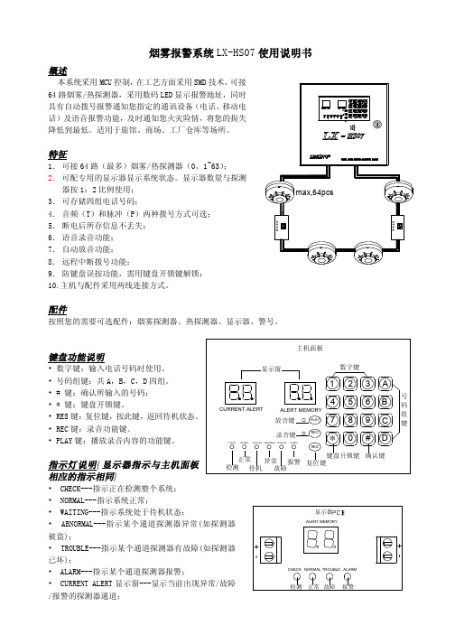


烟雾报警器说明书元器件清单;运行原理一旦传感器捕获了外气体浓缩信号,传感器就将其传输给位于整体内的10位模块换能器,该换能器将气体浓缩信号转换为数字信号,然后通过算术处理显示在数字管上。
tic.when检测到的气体浓度大于限定的报警阀值,系统产生报警、声纳、中继器。
吸收,吸收警报阀值可由外部按钮定义(“警报阀值”)系统默认为200ppm。
警报阀调节步骤:按K1&Amp;‧;调整键&Amp;‧;输入警报值调整菜单,数字管显示当前警报阀值,按K2&Amp;‧;‧‧;‧‧;以及警报阀值&Amp;‧‧;1&Amp‧;当您设定警报阀的值时,请按K1&Amp;‧键;调节键&Amp;‧;系统离开调节菜单进入烟雾浓度测量显示菜单。
介绍系统的主要组成部分单片:STC12C5A60S2/ADPWM单片系列STC12C5A60S2/ADPWM是一种单片时钟循环机,由大晶体技术生产,是一种新的8051高速、低功耗、耐干扰的单片机,而指令代码完全符合8051传统,但速度为8到12倍的PWM电路,8条高速公路,10个AD开关(250K/S,用于发动机控制,高干扰)。
烟雾传感器:MQ-2气体传感器所用的空气敏感性材料是二氧化锡(“SNO2”),在空气中具有低导电率。
清理一种燃料气体位于传感器所处的环境中其电导率随着燃料气体浓度的增加而增加。
第一次来简单电路将导电率变化转换成与气体浓度相应的输出信号。
MQ-2气体传感器对液化气体、丙烷和氢非常敏感,并且能够检测天然气和其他可燃蒸汽。
欧洲联盟传感器检测多个易燃气体,并且是适合于多种应用的低成本传感器。
MQ-2空气敏感性元件的结构和形状见图1(“结构A或B”,由陶瓷管A1203、SND2敏感层、测量电极和加热装置组成的敏感性元件,固定在塑料腔或不锈钢腔中,加热装置为空气敏感性元件提供工作带。
烟雾探测报警器产品规格说明书(BL-WJX-YG01)文件编号:201608JX004项目负责人:张伟伟拟制:林潮仿日期:2016-8-23审核:日期:批准:日期:广东美电贝尔科技集团股份有限公司对本文件资料享受著作权及其它专属权利,未经书面许可,不得将该文件资料(其全部或任何部分)披露予任何第三方,或进行修改后使用。
目录1. 产品简介....................................................................................................................................... - 2 -2. 产品特性....................................................................................................................................... - 2 -3. 产品外观....................................................................................................................................... - 2 -4. 技术参数....................................................................................................................................... - 3 -1.产品简介烟雾探测报警器(BL-WJX-YG01)是一款用于检测单位面积内烟雾浓度数据,当烟浓度达到设定值时报警器会触发报警信号输出,在固定面积空间内安装符合量的报警器,可有效监测空间内火灾发生情况。
The Firex 4618 Smoke Alarm is an ionization 120V AC smoke alarm with battery back-up for single or multiple station use. It includes a Quick Quiet TM False Alarm Control TM feature which allows the user to quiet an unwanted alarm for up to 15 minutes. The 4618 has a front loading battery door, 85 decibel horn, test switch and dual purpose LED indicator; constant green “power on” confirms AC power is present and the flashing red displays alarm/battery status. The Latching LED feature clearly identifies the smoke alarm that initiated an alarm in an interconnected system with a flashing red LED. The LED will remain flashing until the test button is depressed on that unit. Our unique PowerLink TM Tab is designed to allow the smoke alarm to be shipped with the battery already installed. It keeps the door from closing until installation, which prevents the battery from draining prematurely. The installer simply removes the PowerLink TM Tab, closes the door and tests the unit. This results in a faster installation time. The dust cover eliminates nuisance call-backs by keeping construction dust and debris from causing false alarms.This smoke alarm mounts to any single or 4” octagon junction box or square-to-round drywall ring and has 8” long pigtails with a Quick Connect harness for permanent connection. The 4618 is interconnectable with up to 11 other compatible Firex smoke alarms and 6 Firex heat, carbon monoxide or smoke/CO combo alarms for a total of not more than 18 Firex devices. When interconnected with other Firex smoke alarms, the unit that initiates an alarm will display a rapidly flashing red LED while the other interconnected alarm LED's remain extinguished. This Firex unit should be placed in single-family households or in each individual living unit of multiple-family buildings.5Year Limited WarrantyAn ISO 9002 Certified Company 120V ACDirect Wire WithBattery Back-up andQuick Quiet™False Alarm Control™PowerLink Tab™ makes installation faster and easierthan ever. Simply pull tab, close door and press test button!NEW Alarm LocatorRed LED flashes until reset for quick, clearidentification of the initiating alarm in aninterconnected system.Front loading battery doorMakes battery changing simple.PowerLink™ TabMakes installation faster and easier than ever.Quick Quiet™ False Alarm Control™Quiets unwanted alarms forup to 15 minutes.NEW Visible Low Battery IndicatorHelps locate chirping unit.Interconnects with other Firexsmoke and heat alarmsCompatible with other contractor preferredFirex devices.NEW Ramp-Up Test HornAllows you to test the unit without the ear-piercing horn.Factory sealed housingPrevents tampering and provides outstandingdurability.Dust CoverEliminates nuisance call-backs.Attractive low-profile designFavorite among consumers.Side ViewMounting Bracket150-1521EInstallation of Smoke AlarmItem 4618ModelFADC Product Weight8 ounces Operating Temperature 40°to 100°FInterconnect QtyUp to 18 Firex devices maximum: smoke alarm items 5000 (model FADC), 4418 (model AD), 4518 (model ADC), 4480 (model PAD), Firex heat alarm item 5700 (model ADH), CO alarm items 10000 (COE), 6045 (model COQ8),smoke &CO alarm item 7000 (model FADCQ) (up to 6heat, CO, smoke CO alarms max.)Electrical Rating120V AC, 60HZ, 50mA max, 9 Volt Battery Back-up Alarm Point obs. 1.35 ±0.7%/ft.Horn Output 85 decibels at 10 feet Listing4618 — U.L. 217Detection Type Dual ionization chamber Humidity Range10% to 93% relative humidityThe smoke alarm shall be a Styleline design TM (1-5/8” high, 5” wide),powered by a 120 VAC, 60 Hz source with a 9 volt battery back-up.The alarm shall have a “quick connect” molded harness and front loading battery door. The alarm shall have a dual chamber ionization sensor. The alarm shall be rated at no greater than .5W in standby.Nominal sensitivity shall be measured by U.L. at obs. 1.35 ±0.7%/ft.Temperature operating range shall be between 40°and 100°F (4°-38°C); humidity range between 10%-93% relative humidity; 100%solid state alarm circuits over an input range of 100-130 VAC. A green continuous power-on indicator shall be a built-in light emitting diode in the standby condition; a second red flashing LED shall indicate that a sufficient 9-volt battery back-up is present; when activated the initiating alarm red LED shall remain illuminated while theinterconnected alarm LEDs are extinguished. The Quick Quiet TM False Alarm Control TM feature shall desensitize the alarm for 15 minutes.The red LED shall blink once every 10 seconds when in Quick Quiet TM False Alarm Control TM and the alarm shall produce two short chirps 2seconds apart at the conclusion of the desensitized period. The test switch shall electronically activate the chamber to simulate smoke and check for proper operation. The electronic horn shall have a level of 85 decibels at 10 feet. The alarm shall mount to a single gang box,4” octagon junction box, or a square to round drywall ring without screw removal. It shall have a pigtail wiring, separate mounting bracket. The 4618 shall meet the requirements of U.L. Standard 217.This smoke alarm should be installed in accordance with the NFPA’s Standard 72 (National Fire Protection Association, Batterymarch Park,Quincy, MA 02269) and any local codes that apply.When interconnecting, use #18 AWG minimum solid or stranded wire.Maximum wire length between any two is 1,500 feet for #18 AWG or 4,000 feet for #14 AWG (20 OHMS loop resistance).DO NOT connect to any other type or model of smoke, heat, CO or smoke/CO combo alarm. Connect smoke, heat, CO or smoke/CO combo alarms to a single AC branch circuit. If local codes do not permit, be surethe neutral wire is common to both phases.120V ACDirect Wire With Battery Back-up and Quick Quiet™False Alarm Control™5”Controls Americas 191 E. North AvenueCarol Stream, Illinois 60188 USACust. Service Telephone +1 800 951 5526Cust. Service Facsimile +1 630 260 7299For Technical ServiceTelephone +1 800 445 8299Facsimile +1 630 260 7243*****************************Visit us on the web at ©2005 Invensys Controls Americas3505 Laird Road Unit #14Mississauga, Ontario L5L 5Y7 CanadaCust. Service Telephone +1 800 668 6958Cust. Service Facsimile +1 905 828 1265。
2023年智能烟雾报警器使用手册一、产品简介智能烟雾报警器是一种通过感知环境中的烟雾浓度并及时发出警报的设备。
它具有灵敏度高、反应迅速、操作简便等特点,旨在提供更安全的居住环境。
本使用手册旨在帮助用户正确使用和维护智能烟雾报警器,以确保其最佳性能和可靠性。
二、安装步骤1. 确保安装位置:安装前应仔细选择合适的位置,避免直接受潮、通风过大或者烟雾无法达到的位置。
2. 安装高度:建议将智能烟雾报警器安装在房间中央的天花板上,避免安装在墙角或者靠近门窗等位置。
3. 安装固定座:将固定座固定在天花板上,注意使用合适的固定工具。
4. 安装烟雾报警器:将烟雾报警器插入固定座,确保安装牢固。
三、使用方法1. 开关机:烟雾报警器具有自动开关机功能,请勿手动开关。
当烟雾报警器处于工作状态时,绿色指示灯会亮起;当处于静默状态时,指示灯熄灭。
2. 测试功能:为了确保烟雾报警器的正常工作,我们建议每月进行一次测试。
轻轻按压报警器顶部的测试按钮,听到蜂鸣声即表明报警器正常工作。
3. 报警处理:当烟雾浓度超过安全阈值时,报警器将会发出持续响铃,并激活报警信号。
此时,请立即采取以下措施:a. 验证烟雾:先用手背接触门缝,判断门背后是否有浓烟。
如有浓烟,请不要打开房门,以免吸入有害气体。
b. 打开窗户:如未感知浓烟,请小心地打开窗户,增加通风,从而减少烟雾的积聚。
c. 联系救援:迅速拨打当地消防电话或报警电话,告知现场情况,并按照救援人员的指示行动。
四、注意事项1. 定期检测:用户应每三个月对智能烟雾报警器进行一次自检,确保其正常工作。
2. 清洁报警器:使用吸尘器或干净的软布轻轻擦拭报警器表面,确保不会使用化学清洁剂或水清洗。
3. 避免误触发:在烟雾报警器附近避免做饭时产生大量油烟或蒸汽,以免误触发报警器。
4. 电池更换:智能烟雾报警器采用可拆卸电池供电,请根据指示灯提示及时更换电池。
五、维修与保养1. 维修保养:如发现智能烟雾报警器存在故障或异常,请立即停止使用,并联系生产商或专业技术人员进行检修。
SpecificationsThe contents of this document are provided on an “as is” basis. No representation or warranty (either express or implied) is made as to the completeness, accuracy or reliability of the contents of this document. The manufacturer reserves the right to change designs or specifications without obligation and without further notice. Except as otherwise provided, all warranties, express or implied, including without limitation any implied warranties of merchantability and fitness for a particular purpose are expressly excluded.Xtralis, the Xtralis logo, The Sooner You Know, VESDA-E, VESDA, ICAM, ECO, OSID, HeiTel, ADPRO, IntrusionTrace, LoiterTrace, ClientTrace,SmokeTrace, XOa, XOh, iTrace, iCommand, iRespond, iCommission, iPIR, and FMST are trademarks and/or registered trademarks of Xtralis and/or its subsidiaries in the United States and/or other countries. Other brand names mentioned herein are for identification purposes only and may be trademarks of their respective holder(s). Your use of this document does not constitute or create a licence or any other right to use the name and/or trademark and/or label.This document is subject to copyright owned by Xtralis. You agree not to copy, communicate to the public, adapt, distribute, transfer, sell, modify or publish any contents of this document without the express prior written consent of UK and Europe +44 1442 242 330 D-A-CH +49 431 23284 1 The Americas +1 781 740 2223Middle East +962 6 588 5622 Asia +86 21 5240 0077 Australia and New Zealand +61 3 9936 7000Part: 30359Ordering InformationVESDA-E VEA-40 Aspirating Smoke Detector with LEDsVEA-040-A00VESDA-E VEA-40 Aspirating Smoke Detector with 3.5” DisplayVEA-040-A10VESDA-E VEA-20 Expansion StaX VEA-020-STX VESDA-E VEA-40 Expansion StaX VEA-040-STX VESDA-E VEA 40-Relay Local StaX VER-A40-40-STX Sampling Point for 6mm TubeVSP-980Sampling Point for 6mm Tube (22 pack)VSP-980-22Sampling Point for 6mm Tube (44 pack)VSP-980-44Sampling Point for 4mm TubeVSP-981Sampling Point for 4mm Tube (22 pack)VSP-981-22Sampling Point for 4mm Tube (44 pack)VSP-981-44Spare PartsVESDA-E VEA-40 Mounting Bracket VSP-970VESDA-E VEA-40 Smoke Sensor Module VSP-971VESDA-E VEA Filter VSP-972VESDA-E VEA Pump VSP-973VESDA-E VEA Rotary ValveVSP-974VESDA-E VEA-040-A00 Fascia with LEDs VSP-975VESDA-E VEA-040-A10 Fascia with 3.5” DisplayVSP-976Supply Voltage:18 to 30 VDCPower Consumption @ 24VDC:Peak current (scan mode) 3.5A (for initial 5 seconds of scanning)AspiratorLinear Vacuum PumpDimensions (WHD): 352 mm x 336 mm x 135.5 mm (13.9in x 13.2in x 5.33in)Weight: VEA-040-A00: 9.9 kg (21.8 lbs)VEA-040-A10: 10 kg (22.2 lbs)Operating Conditions: Ambient: 0°C to 39°C (32°F to 102°F) Sampled Air: 0°C to 50°C (32°F to 122°F) Tested to: 0°C to 49°C (32°F to 120°F)*Humidity: 10% to 95% RH, non-condensing Microbore Tube Size: OD: 6 mm, ID 4 mmOD: 4 mm, ID 2.5 mm Microbore Tube Length:Up to 100m (330 ft)Flow Monitoring: Single sampling point and single tube blockage and breakage detection Relays: 7 programmable relays (latch or non-latch states)Contacts rated 2 A @ 30 VDC (Resistive)IP Rating: IP40Cable Access: 4 x 25 mm (1”) cable entriesCable Termination: Screw Terminal blocks 0.2–2.5 sq mm (24 - 14 AWG)Pre-alarms: Alert and Action - two pre alarm levels Sensitivity:0.020%/m (0.006%/ft) - 16%/m (4.88%/ft)Fire-1 Alarm Thresholds High: 1.6 %/m (0.5 %/ft)at the Sampling Hole: Enhanced 4.0 %/m (1.3 %/ft)Standard8.0 %/m (2.5 %/ft)Communication Interfaces: USB (Type 2), Ethernet (RJ45), WiFi (802.11 b/g/n)Software Features: Event log: Up to 20,000 events stored in FIFO format, smokelevel, user actions, alarms and faults with time and date stampApprovals CompliancePlease refer to the Product Guide for details regarding compliant design, installation and commissioning.Doc. no. 22210_09How it worksThe VEA detector draws a combined air sample from a network of microbore flexible tubing from allsampling points in the protected area, then filters and analyzes the sample in laser detection chambers in the smoke sensor module. When smoke particles are detected and the smoke level reaches set alarm thresholds, the system will raise appropriatealarm conditions. After a Fire 1 alarm is raised, the system will sequentially scan the sampling locations via the rotary valve to identify one or more sampling locations with the fire alarm event. To assist in investigation of the source of a fire, if the system is in Pre-Alarm, the user can initiate a smoke scan of all sampling locations.The VEA uses a vacuum pump which provides superior detection times for long tube lengths. The system monitors the airflow within the installation, allowing detection of breakages or blockages of individual sampling points and sampling tubes, with faults indicated on the display and to the monitoring equipment.Alarms and fire location can besignaled via Relays and VESDAnet. Ethernet and WiFi can be used for configuration and secondary monitoring, and a USB interface is provided for field installation andmaintenance. The optional Relay StaX module can be used to identify and signal fire source locations on a fire panel loop.A series of LEDs display Alarm,Trouble, Disable and detector power on status. A button allows the user to Reset or Disable the detector. Additionally, the VEA-A10 features a 3.5” LCD display which shows detector status.Expansion to 60, 80, 100 or 120 sampling points can be achieved by installing additional Expansion StaX modules.VEA-040-A00VEA-040-A10Quiescent22 W 23 W Alarm Average35.5 W36.5 W* Product UL Listed between 0°C to 39°C (32°F to 102°F)。