E系列网络高清球机快速指南
- 格式:pdf
- 大小:1.89 MB
- 文档页数:26

V2.3 2021.05前言Kedacom™、TrueSens™、、为苏州科达科技股份有限公司的商标,不得擅自使用。
苏州科达科技股份有限公司版权所有,保留所有权利。
本手册可能包含技术上不准确的地方、或与产品功能及操作不相符的地方、或印刷错误。
我司将根据产品功能的增强而更新本手册的内容,并将定期改进或更新本手册中描述的产品或程序。
更新的内容将会在本手册的新版本中加入,恕不另行通知。
通过互联网访问说明将本产品接入互联网需自担风险,包括但不限于产品可能遭受的网络攻击、黑客攻击、病毒感染等,本公司不对因此造成的产品工作异常、信息泄露等问题承担责任,本公司将及时为您提供产品相关技术支持。
注意为了提高产品网络使用的安全性,建议您设置高强度密码,密码必须包含8-16 个字符,且至少由数字、字母或特殊字符中的两种或两种以上类型组合而成。
请您定期更改用户名的密码,建议每3 个月更新一次。
如果设备在较高安全风险的环境中使用,建议每月或每周更新一次。
请妥善保管好您的用户名与密码。
环保声明请遵守有关设备包装材料、耗尽电池和废旧设备处理的本地法规,并支持回收行动。
读者对象监控产品管理员、操作人员。
适用软件版本7.2.3关于本手册本手册用于指导用户操作,手册中的界面截图、图表等仅用于解释和说明的目的,与具体产品可能存在差异,请以实际为准。
本书约定“”苏州科达科技股份有限公司地址:江苏省苏州市高新区金山路131号邮编:215011 网址:电话:*************传真:*************客户咨询热线:400-828-2866此内容的目的是确保用户正确使用本产品,以避免危险或财产损失。
在使用此产品之前,请认真阅读此手册并妥善保存以备日后参考。
如果因为没有按照本手册说明的正确操作,而产生的事故,本公司概不负责,亦不承担任何相关法律责任。
设备安装前,请确保符合安装要求。
注意事项1) 请使用满足安全电压要求的电源。
2) 如果设备工作不正常,请联系购买设备的商店或最近的服务中心,不要以任何方式随意拆卸或修改设备(未经许可的修改或维修所导致的问题,责任自负)。

高清网络高速球型摄像机安装手册HDH5407E-H65-R21HDH5007E-H65-R21感谢您选用本公司的产品,请您在使用本产品前仔细阅读用户手册,本用户手册将为您提供正确的安装和使用说明.版权声明:本用户手册版权归天津市亚安科技电子有限公司所有,未经本公司许可,任何机构和个人不得抄录,转载其中全部或部分内容.“天津市亚安科技电子有限公司保留因产品性能改进而对本用户手册修改和更新的权利,更新内容恕不一一通知用户.”您在使用过程中如遇到本手册未能述及的问题,请与本公司或本公司的合法经销商联系.您可以随时登录本公司的网站,了解相关产品的最新消息.目录1安全注意事项 (3)1.1警告 (3)1.2注意 (3)2产品介绍 (5)2.1术语 (5)2.2产品应用 (7)2.3技术指标 (8)2.4引用国家标准、行业标准 (9)3安装 (9)3.1安装前确认 (9)3.2安装准备 (10)3.2.1安装人员要求 (10)3.2.2线缆准备 (10)3.2.3安装工具 (11)3.2.4核查安装地点 (11)3.3开始安装 (12)3.3.1结构说明 (12)3.3.2组装示意 (12)3.3.3壁挂式安装 (14)3.3.4角式安装 (16)3.3.5吊臂式安装 (18)3.3.6柱式安装 (19)4维护和修理 (21)4.1日常维护 (21)4.2简易故障及维修 (21)1安全注意事项1.1警告1.1.1 安装和使用本设备之前,请仔细阅读用户手册,并妥善保管,以便日后使用。
1.1.2 应遵守产品上和用户手册上的所有警告事项,遵守全部指示操作和使用说明。
1.1.3 在擦拭前,先断开电源,勿用液体或喷雾式清洁剂,请用湿布擦拭。
1.1.4 应使用经销商或本公司推荐的配件,否则可能会导致故障。
1.1.5 本产品应使用用户手册规定的电源种类和电压,如安装地点的电源和电压不明确,请与经销商或本公司联系。
1.1.6 应妥善保护电源线,接插件和摄像机线缆。

智能球型摄像机V1.0.0前言概述本文档详细描述了如下内容。
标题内容概述介绍智能球的功能特性。
使用准备介绍智能球使用前的设置。
菜单介绍介绍智能球OSD菜单的主要功能及使用方法。
系统连接介绍系统连接和报警连接。
日常维护介绍智能球的日常维护。
符号约定在本文中可能出现下列标志,它们所代表的含义如下:表头表头表示有高度潜在危险,如果不能避免,会导致人员伤亡或严重伤害。
表示有中度或低度潜在危险,如果不能避免,可能导致人员轻微或中等伤害。
表示有潜在风险,如果忽视这些文本,可能导致设备损坏、数据丢失、设备性能降低或不可预知的结果。
表示使用静电敏感的设备时,需防止产生静电。
表示高压危险。
表示强激光辐射。
表示能帮助您解决某个问题或节省您的时间。
表示是正文的附加信息,是对正文的强调和补充。
重要安全须知以下是关于产品的正确使用方法以及预防危险、防止财产受到损失等内容,使用设备前请仔细阅读本说明书并在使用时严格遵守,阅读后请妥善保存说明书。
电源要求●在本产品安装使用中必须严格遵守当地各项电气安全标准。
请使用满足SELV(安全超低电压)要求的电源,并按照IEC60950-1符合Limited Power Source(有限电源)的额定电压供应。
●请在安装配线时装入易于使用的断电设备,以便必要时进行紧急断电。
●设备运行之前,请检查供电电源是否正确。
●请保护电源软线免受踩踏或紧压,特别是在插头、电源插座和从装置引出的接点处。
使用环境要求●请避免将设备对准强光(如灯光照明、阳光等)聚焦,否则容易引起过亮或拉光现象(这并非设备故障),也将影响感光器件CCD(或CMOS)的寿命。
●请在允许的湿度和温度范围内运输、使用和存储设备。
不要将设备置于潮湿、极热(超过+60℃)、极冷(低于-20℃)、强电磁辐射或照明条件不稳定等场所。
●请用户使用时不要让水及任何液体流入设备,以免内部元件受损。
●为了避免热量积蓄,请不要阻挡设备附近的通风。
●运输、存储及安装过程中要防止重压、剧烈振动、浸泡等对产品造成的损坏。
DS-2XE Series Explosion-ProofBullet Network CameraQuick Start GuideModel ListDS-2XE6025G0-IDS-2XE6025G0-ISDS-2XE6025G0-IMDS-2XE6045G0-IDS-2XE6045G0-ISDS-2XE6045G0-IM©Hangzhou Hikvision Digital Technology Co.,Ltd.No.555Qianmo Road,Binjiang District,Hangzhou,Quick Start GuideALL RIGHTS RESERVEDAny and all information,including,among others,wordings,pictures, graphs are the properties of Hangzhou Hikvision Digital Technology Co.,Ltd.or its subsidiaries(hereinafter referred to be“Hikvision”). This user manual(hereinafter referred to be“the Manual”)cannot be reproduced,changed,translated,or distributed,partially or whol-ly,by any means,without the prior written permission of Hikvision. Unless otherwise stipulated,Hikvision does not make any warran-ties,guarantees or representations,express or implied,regarding to the Manual.About this ManualThis Manual is applicable to Bullet Network Camera.The Manual includes instructions for using and managing the prod-uct.Pictures,charts,images and all other information hereinafter are for description and explanation only.The information contained in the Manual is subject to change,without notice,due to firmware updates or other reasons.Please find the latest version in the com-pany website(/en/).Please use this user manual under the guidance of professionals.Trademarks Acknowledgementand other Hikvision’s trademarks and logos are the properties of Hikvision in various jurisdictions.Other trademarks and logos mentioned below are the properties of their respective owners.Legal DisclaimerTO THE MAXIMUM EXTENT PERMITTED BY APPLICABLE LAW,THE PRODUCT DESCRIBED,WITH ITS HARDWARE, SOFTWARE AND FIRMWARE,IS PROVIDED“AS IS”,WITH ALL FAULTS AND ERRORS,AND HIKVISION MAKES NO WARRAN-TIES,EXPRESS OR IMPLIED,INCLUDING WITHOUT LIMITA-TION,MERCHANTABILITY,SATISFACTORY QUALITY,FITNESS FOR A PARTICULAR PURPOSE,AND NON-INFRINGEMENT OF THIRD PARTY.IN NO EVENT WILL HIKVISION,ITS DIRECTORS, OFFICERS,EMPLOYEES,OR AGENTS BE LIABLE TO YOU FOR ANY SPECIAL,CONSEQUENTIAL,INCIDENTAL,OR INDIRECTDAMAGES,INCLUDING,AMONG OTHERS,DAMAGES FOR LOSS OF BUSINESS PROFITS,BUSINESS INTERRUPTION,OR LOSS OF DATA OR DOCUMENTATION,IN CONNECTION WITH THE USE OF THIS PRODUCT,EVEN IF HIKVISION HAS BEEN ADVISED OF THE POSSIBILITY OF SUCH DAMAGES. REGARDING TO THE PRODUCT WITH INTERNET ACCESS,THE USE OF PRODUCT SHALL BE WHOLLY AT YOUR OWN RISKS. HIKVISION SHALL NOT TAKE ANY RESPONSIBILITES FOR AB-NORMAL OPERATION,PRIVACY LEAKAGE OR OTHER DAM-AGES RESULTING FROM CYBER ATTACK,HACKER ATTACK, VIRUS INFECTION,OR OTHER INTERNET SECURITY RISKS; HOWEVER,HIKVISION WILL PROVIDE TIMELY TECHNICAL SUPPORT IF REQUIRED.SURVEILLANCE LAWS VARY BY JURISDICTION.PLEASE CHECK ALL RELEVANT LAWS IN YOUR JURISDICTION BEFORE USING THIS PRODUCT IN ORDER TO ENSURE THAT YOUR USE CONFORMS THE APPLICABLE LAW.HIKVISION SHALL NOT BE LIABLE IN THE EVENT THAT THIS PRODUCT IS USED WITH ILLEGITIMATE PURPOSES.IN THE EVENT OF ANY CONFLICTS BETWEEN THIS MANUAL AND THE APPLICABLE LAW,THE LATTER PREVAILS. Regulatory InformationFCC InformationPlease take attention that changes or modification not expressly ap-proved by the party responsible for compliance could void the user’s authority to operate the equipment.FCC compliance:This equipment has been tested and found to com-ply with the limits for a Class B digital device,pursuant to part15of the FCC Rules.These limits are designed to provide reasonable protection against harmful interference in a residential installation.This equip-ment generates,uses and can radiate radio frequency energy and,if not installed and used in accordance with the instructions,may cause harmful interference to radio communications.However,there is no guarantee that interference will not occur in a particular installation.If this equipment does cause harmful interference to radio or television reception,which can be determined by turning the equipment off and on,the user is encouraged to try to correct the interference by one or more of the following measures:—Reorient or relocate the receiving antenna.—Increase the separation between the equipment and receiver.—Connect the equipment into an outlet on a circuit different from that to which the receiver is connected.—Consult the dealer or an experienced radio/TV technician for help FCC conditionsThis device complies with part15of the FCC Rules.Operation is sub-ject to the following two conditions:1.This device may not cause harmful interference.2.This device must accept any interference received,including interfer-ence that may cause undesired operation.EU Conformity StatementThis product and-if applicable-the supplied accessoriestoo are marked with"CE"and comply therefore withtheapplicable harmonized European standards listed underthe the EMC Directive2014/30/EU,the RoHS Directive2011/65/EU.2012/19/EU(WEEE directive):Products marked withthis symbol cannot be disposed of as unsorted municipalwaste in the European Union.For proper recycling,returnthis product to your local supplier upon the purchase ofequivalent new equipment,or dispose of it at designatedcollection points.For more information see:www.2006/66/EC and its amendment2013/56/EU(batterydirective):This product contains a battery that cannot bedisposed of as unsorted municipal waste in the EuropeanUnion.See the product documentation for specific batteryinformation.The battery is marked with this symbol,whichmay include lettering to indicate cadmium(Cd),lead(Pb),or mercury(Hg).For proper recycling,return the battery toyour supplier or to a designated collection point.For moreinformation see:.Industry Canada ICES-003ComplianceThis device meets the CAN ICES-3(B)/NMB-3(B)standards require-ments.These instructions are intended to ensure that the user can use the product correctly to avoid danger or property loss. Laws and RegulationsThe device should be used in compliance with local laws, electrical safety regulations,and fire prevention regulations. TransportationKeep the device in original or similar packaging while transporting it.Power SupplyThe input voltage should conform to IEC60950-1standard: SELV(Safety Extra Low Voltage)and the Limited Power Source.Refer to the appropriate documentation for detailed information.DO NOT connect multiple devices to one power adapter,to avoid over-heating or fire hazards caused by overload. Make sure the plug is properly connected to the power socket.System SecurityThe installer and user are responsible for password and security configuration and its settings.BatteryImproper use or replacement of the battery may result in explosion hazard.Replace with the same or equivalent type only.Dispose of used batteries in conformance with the local codes.MaintenanceIf the product does not work properly,please contact your dealer or the nearest service center.We shall not assume any responsibility for problems caused by unauthorizedrepair or maintenance.A few device components(e.g.,electrolytic capacitor) require regular replacement.The average lifespan varies, so periodic checking is recommended.Contact your dealer for details.CleaningPlease use a soft and dry cloth when clean inside and outside surfaces of the product cover.Do not use alkaline detergents.Using EnvironmentWhen any laser equipment is in use,make sure that the device lens is not exposed to the laser beam,or it may burn out.Do not expose the device to high electromagnetic radiation or dusty environments.For indoor-only device,place it in a dry and well-ventilated environment.Do not aim the lens at the sun or any other bright light. Make sure the running environment meets the requirement of the device.The operating temperature shall be-30°C to 60°C(-22°F to140°F),and the operating humidity shall be95%or less(no condensing).Do not place the camera in extremely hot,cold, dusty or damp locations,and do not expose it to high electromagnetic radiation.EmergencyIf smoke,odor,or noise arises from the device,immediately turn off the power,unplug the power cable,and contact the service center.Time SynchronizationSet up camera time manually for the first time access if the local time is not synchronized with that of the network.Visit the camera via Web browse/client software and go to time settings interface.InstallationMake sure the device is firmly secured to any wall or ceiling mountings.Be sure that there is enough space to install the camera and accessories.Make sure that the device in the package is in good condition and all the assembly parts are included.Make sure that the wall is strong enough to withstand at least4times the weight of the camera and the mount.The standard power supply is24VDC,please make sure your power supply matches with your camera.Make sure that the power has been disconnected before you wire,install,or disassemble the device.Make sure that no reflective surface is too close to the camera lens.The IR light from the camera may reflect back into the lens causing reflection.For device with this sticker,this device is intended for installation in a restricted access location,access can only be gained by service persons or by users who have been instructed about the reasons for the restrictions applied to the location and about any precautions that shall be taken. GroundingThe both internal and external grounding shall be connected reliably.Ground wire cross-sectional area of not less than the phase connector cross-sectional area level,at least4mm².Intended use of the cameraATEX:II2G Ex db op is IIC T6GbII2D Ex op is tb IIIC T80℃Dbll:Device group,ll refers to the gas or dust in non-mining environment2:Device usage classification(Zone1,21)G:Gas environmentD:Dust environmentEx:Explosion-proof signdb:Flameproof enclosures"d",EPL"Gb";db/tb:Dust-Protection by enclosure"t";EPL"Db";op is:Optical radiation,inherently safellC:Classification sign,typical gases are hydrogen and acetylene.lllC:Classification sign,conductive dust.T80℃:for dust environment,maximum surface temperatureT6:Temperature group for gas environment,maximum surface temperature is85℃Gb/Db:Protection level of the deviceIECEx:Ex db op is IIC T6Gb/Ex op is tb IIIC T80℃Db Ex:Explosion-proof signdb/tb:Protection by enclosureop is:Optical radiation,inherently safellC:Classification sign,the hydrogen in gas environmentlllC:Classification sign,conductive dust in dust environmentT80℃:Maximum surface temperatureT6:Temperature group,maximum surface temperature is85℃Gb/Db:Protection level of the deviceHazardous Area Classification:Zone1,Zone2,Zone21,Zone22.IP Degree:IP68(2m,2h)Ex Standards:IEC60079-0:2017EN60079-0:2012+A11:2013IEC60079-1:2014EN60079-1:2014IEC60079-31:2013EN60079-31:2014IEC60079-28:2015EN60079-28:2015Special Conditions for Safe Use:1.Ambient Temperature:-30°C to+60°C.2.DO NOT OPEN WHEN ENERGIZED.3.When assembly,operation and maintenance,the operator must follow the requirements of the EN/IEC 60079-14:latest version Explosive atmosphere-Part14: Electrical installation design,selection and erection,beside of the manufacturer’s operation instruction or its National equivalent.4.Repair and overhaul shall comply with EN/IEC60079-19: latest version or its National equivalent.5.The both internal and external earthing shall be connected reliably.6.The cable is fixed by cement,end-user cannot replace it by themselves.Industry Canada ICES-003ComplianceThis device meets the CAN ICES-3(B)/NMB-3(B)stan-dards requirements.Warning:1.This is a class B product.In a domestic environment this product may cause radio interference in which case the user may be required to take adequate measures.2.The cables cannot be exposed to the explosion-hazardous environment.3.The connections of the cables must be placed in non-explosive areas or the explosion-proof junction box that can be used in explosive environment.OverviewExplosion-proof network camera is a video security product capable of smart encoding and network transmitting.It adopts an embedded system and a high-performed hardware process platform to achieve good stability and reliability. You can visit and configure your camera via web browser and client software.Explosion-proof network camera adopts a stainless steel enclosure,receiving an IP68rating for ingress protection. Application Scenarios:bus,car or other vehicles,etc.With-I model camera has LEDs and supports IR function,so it must follow the requirements of IEC60079-28:2015 and EN60079-28:2015.Explanation of model naming:Nameplate:Activate and Access Network CameraScan the QR code to get Activate and Access Camera.Note that mobile data charges may apply if Wi-Fi is unavailable.UD12125B-B。
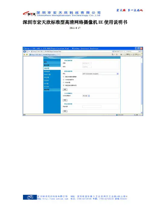
深圳市宏天欣标准型高清网络摄像机IE使用说明书2011-6-17目录1.设备安装 (3)2.操作指南 (4)2.1登录设备 (4)2.2视频配置 (6)2.3网络参数配置 (7)2.4 DDNS域名配置 (8)2.5 版本升级 (9)2.6用户管理 (10)2.7 密码修改 (11)2.8 SMTP邮件服务器 (11)2.9 FTP配置 (12)2.10 Alarm Event配置 (13)2.11 移动探测 (14)2.12System Log (15)附录一、常见问题 (16)1.IE浏览器里没有插件显示 (16)2.无法通过IE浏览器访问 (16)3.无法观看视频 (16)4.为何我的手机无法安装监控软件? (16)5.使用手机观看视频应该怎样设置? (16)6.点击Restore为何不能恢复IP地址? (17)7.更改IP CAMERA访问端口(HTTP PORT)后为何无法使用手机或客户端软件观看视频? (17)8.设置了画面弹出,为何客户端软件报警后不会弹出报警提示窗口? (17)9.如何将内网IP CAMERA映射出公网环境? (17)1.设备安装注意事项1.拆开包装盒时请仔细检查,确认其中的物品与清单一致。
2.安装前请仔细阅读本章内容。
3.安装时,请务必关闭所有相关设备电源。
4.检查电源电压,防止出现电压不配导致器件损坏。
5.安装环境:请勿在超标的潮湿或高温环境下使用,请保持通风良好,注意防雨淋;避免安装在剧烈震动的环境下。
6.如果设备工作不正常,请联系购买设备的经销商或最近的服务中心,请不要以任何方式拆卸或修改设备。
未经许可的修改或维修所导致的问题,责任自负。
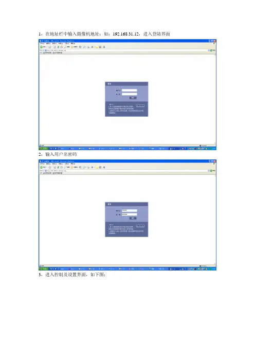
运行环境操作系统: Windows2000server/professional/XP网络协议: TCP/IP客户端PC:P4/128MRAM/40GHD/ 支持缩放的显卡,DirectX8.0以上支持当前已测试过的显卡列表:显卡名称工作情况SiS 650/651/740/661 FX/741/760 Series可以正常显示视频Intel(R) 82945R Express Chipset Family可以正常显示视频VIA/S3G UniChrome Pro IGP可以正常显示视频NIVDIA Geforce 7300GS可以正常显示视频SiS 661FX可以正常显示视频SiS Mirage Graphics可以正常显示视频SiS 661 Series可以正常显示视频Intel(R) G33/G31 Express可以正常显示视频SiS Mirage3 Graphics可以正常显示视频SiS 661FX/GX Mirage Graphics可以正常显示视频Intel 965 Express Chipset Family 可以正常显示视频ATI Mobility Radeon X1300 可以正常显示视频Intel( R ) G45/G43 Express Chipset 可以正常显示视频Mobile Intel 965 Express Chipset Family 可以正常显示视频Mobile Intel(R) 4 Series Express Chipset Family 可以正常显示视频Mobile Intel® 945GM Express Chipset Family 可以正常显示视频Mobile intel® 915GM/GMS, 910GML Express Chipset可以正常显示视频FamilyIntel® G45/G43 Express Chipset 可以正常显示视频ATI Technologies, RAGE XL PCI不能显示视频画面S3 Graphics ProSavageDDR(Microsoft Corporation) 不能显示视频画面XGI Velari Z7/Z9/Z9S V1.08.12 显示视频画面有延迟网线的制作(1)网络摄像机的网口与HUB相连的双绞线(直通线):(2)网络摄像机的网口与PC机相连的双绞线(交叉线):2.操作指南2.1登录设备打开电脑中的IE浏览器,在IE地址栏中输入http://192.168.1.168(默认地址)登录,进入登录界面后输入默认的用户名和密码,User:admin,Password:admin。

网络高速球使用手册目录安全注意事项3一、技术指标31.1高速球技术参数 41.2网络技术参数 4二、性能特点5球机性能: 5 网络性能: 6三、设备安装及网络连接63.1 壁挂式、吊装式高速球安装方式、外形尺寸: 63.2 安装准备73.3 壁挂式高速球安装83.4 吊装式高速球安装93.5主要接口103.6 网络连接方法11 网络连接示意图113.7 通电11四、球机的功能设置124.1 高速球波特率、协议设置124.2 高速球功能设置表13安全注意事项1. 运输及保管过程中要防止重压、剧烈振动和浸泡等对产品造成的损坏。
2. 本产品为吊装在天花板顶部或安装在墙壁上的设计,不可将本产品颠倒安装;对机芯要轻拿轻放,勿用力挤压各结构部件,否则可能引起机械故障,影响球机整体性能。
球机透明罩属于高级光学产品,避免用手直接触摸,以免透明罩划伤,影响图像质量。
3.请勿将任何异物或流体物质渗入机器中,以免损坏机器。
4.接线时必须遵守各项电气安全标准,使用本机自带的专用电源。
本产品RS-485及视频信号采用TVS级防雷击技术,可以有效防止500W以下功率的雷击、浪涌等各类脉冲信号对设备造成的损坏。
RS-485及视频信号在传输过程中应与高压设备或电缆保持足够的距离,必要时还要做好防雷击、防浪涌等防护措施。
5.无论是使用中或非使用中,绝不可以使摄像机瞄准太阳或其它的光亮物体。
否则可能造成像机CCD永久受损。
6. 本产品内部并无用户可自行维修的部件。
当机器有故障时,请勿轻易对机器进行任何修理操作,应先参照说明书查出故障,查不出原因则请专业人员维修。
有关维修工作,必须由我公司授权的维修人员进行。
一、技术指标1.1高速球技术参数1.2网络技术参数二、性能特点球机性能:◆采用功能完善的高性能数字DSP设计, 性能稳定.◆一体化集成设计, 结构紧凑, 可靠性高.◆精密步进电机驱动, 运行平稳, 定位准确.◆采用EEPROM数据存储方式,断电后存储数据不丢失.◆内置自动识别SONY、HITACHI、CANON、 LG、LG-LM、SAMSUNG、KTC、CNB等品牌摄像机的机芯程序. 可根据用户的需求添加其它摄像机程序.◆支持128个预置位的设置及调用, 定位准确.◆支持四组巡航, 每组最多可存储16个预置位.◆支持左右扫描, 低速, 中速, 高速三档可选.◆支持360o扫描, 低速, 中速, 高速三档可选.◆支持看守位功能.◆支持有线报警功能(4路报警输入; 1路报警输出).◆采用导电滑环设计, 水平360°无限制旋转, 无监视盲区.◆支持云台自动翻转功能(垂直方向实现180°自动翻转连续监视).◆支持焦距比例控制功能(云台转速根据镜头变倍值自动调整).◆支持摄像机OSD功能菜单的调用, 设置.网络性能:1、标准MPEG-4 视频压缩格式2、支持D1、CIF、QCIF三种视频格式3、内置Web Server,全面支持IE 浏览器监视、配置和管理,操作简单、方便4、动态的码率控制,保证Internet 上音视频实时传输5、支持双向语音对讲6、支持移动侦测7、支持图像抓拍8、支持图像参数调整9、支持手机查看视频三、设备安装及网络连接3.1 壁挂式、吊装式高速球安装方式、外形尺寸:安装方式及选配器件见下表:注:1.连接工作必须由技术人员或系统安装人员在符合当地规定条件下进行。
Hikvision DS-2DE5425IW-AE (E) 4 MP 25 × Network IR Speed Dome adopts 1/2.8" progressive scan CMOS chip. With the 25 × optical zoom lens, the camera offers more details over expansive areas.This series of cameras can be widely used for wide ranges of high-definition, such as the rivers, roads, railways, airports, squares, parks, scenic spots, and venues, etc.Key Features•1/2.8" progressive scan CMOS•Up to 2560 × 1440@30fps resolution •Excellent low-light performance withpowered-by-DarkFighter technology•25 × optical zoom, 16 × digital zoom •WDR, HLC, BLC, 3D DNR, Defog, EIS, Regional Exposure, Regional Focus•Up to 150 m IR distance•24 VAC & Hi-PoE•Support H.265+/H.265 video compression •Audio input/output•Alarm input/outputCamera ModuleImage Sensor 1/2.8" progressive scan CMOSMin. Illumination Color: 0.005 Lux @(F1.6, AGC ON) B/W: 0.001Lux @(F1.6, AGC ON) 0 Lux with IRWhite Balance Auto/Manual/ATW (Auto-tracking White Balance)/Indoor/Outdoor/FluorescentLamp/Sodium LampGain Auto/ManualShutter Time 50Hz: 1/1 s to 1/30,000 s60Hz: 1/1 s to 1/30,000 sDay & Night IR Cut FilterDigital Zoom 16 ×Privacy Mask 24 programmable privacy masks, mask color configurableFocus Mode Auto/Semi-automatic/ManualWDR 120 dB WDR (not supported by full frame rate)LensFocal Length 4.8 mm to 120 mm, 25 × optical zoomZoom Speed Approx. 3.6 s (optical lens, wide-tele)Field of View Horizontal field of view: 55° to 2.4° (Wide-Tele) Vertical field of view: 33° to 1.4° (Wide-Tele) Diagonal field of view: 61.5 to 2.8° (Wide-Tele)Working Distance 100 mm to 1500 mm (wide-tele)Aperture Range F1.6 to F3.5IRIR Distance150 mSmart IR YesPTZMovement Range (Pan) 360° endlessPan Speed Configurable, from 0.1°/s to 120°/sPreset speed: 120°/sMovement Range (Tilt) From -15° to 90° (auto-flip)Tilt Speed Configurable, from 0.1°/s to 80°/sPreset Speed: 80°/sProportional Zoom YesPresets 300Patrol Scan 8 patrols, up to 32 presets for each patrolPattern Scan 4 pattern scans, record time over 10 minutes for each scanPower-off Memory YesPark Action Preset/Pattern Scan/Patrol Scan/Auto Scan/Tilt Scan/Random Scan/Frame Scan/Panorama Scan3D Positioning YesPTZ Position Display YesPreset Freezing YesScheduled Task Preset/Pattern Scan/Patrol Scan/Auto Scan/Tilt Scan/Random Scan/Frame Scan/Panorama Scan/Dome Reboot/Dome Adjust/Aux OutputCompression StandardVideo Compression Main Stream: H.265+/H.265/H.264+/H.264 Sub-stream: H.265/H.264/MJPEGThird Stream: H.265/H.264/MJPEGH.264 Type Baseline Profile/Main Profile/High ProfileH.264+ YesH.265 Type Baseline Profile/Main Profile/High ProfileH.265+ YesVideo Bitrate 32 Kbps to 16384 KbpsAudio Compression G.711alaw/G.711ulaw/G.722.1/G.726/MP2L2/PCMAudio Bitrate G.711alaw/G.711ulaw: 64 Kbps G.722.1/G.726: 16 KbpsMP212/PCM: 32 Kbps to 160 KbpsSVC YesSmart FeaturesBasic Event Motion Detection, Video Tampering Detection, ExceptionSmart Event Intrusion Detection, Line Crossing Detection, Region Entrance Detection, Region Exiting Detection, Object Removal Detection, Unattended Baggage Detection, Audio Exception DetectionSmart Record ANR (Automatic Network Replenishment), Dual-VCAROI Main stream, sub-stream, and third stream respectively support four fixed areas. Auto-Tracking YesImageMax. Resolution 2560 × 1440Main Stream 50Hz: 25fps (2560 × 1440, 2048 × 1536, 1920 × 1080, 1280 × 960, 1280 × 720) 50fps (1920 × 1080, 1280 × 960, 1280 × 720)60Hz: 30fps (2560 × 1440, 2048 × 1536, 1920 × 1080, 1280 × 960, 1280 × 720) 60fps (1920 × 1080, 1280 × 960, 1280 × 720)Sub-Stream 50Hz: 25fps (704 × 576, 640 × 480, 352 × 288)60Hz: 30fps (704 × 480, 640 × 480, 352 × 240)Third Stream 50Hz: 25fps (1920 × 1080, 1280 × 960, 1280 × 720, 704 × 576, 640 × 480, 352 × 288)60Hz: 30fps (1920 × 1080, 1280 × 960, 1280 × 720, 704 × 480, 640 × 480, 352 × 240) Image Enhancement HLC/BLC/3D DNR/Defog/EIS/Regional Exposure/Regional FocusNetworkNetwork Storage Built-in memory card slot, support Micro SD/SDHC/SDXC, up to 256 GB; NAS (NFS, SMB/ CIFS), ANRAlarm Linkage Alarm actions, such as Preset, Patrol Scan, Pattern Scan, Trigger Recording, Trigger Alarm Output, Notify Surveillance Center, Upload to FTP/Memory Card/NAS, Send Email, etc.Protocols IPv4/IPv6, HTTP, HTTPS, 802.1x, Qos, FTP, SMTP, UPnP, SNMP, DNS, DDNS, NTP, RTSP,RTCP, RTP, TCP/IP, UDP, IGMP, ICMP, DHCP, PPPoE, BonjourAPI ONVIF (Profile S, Profile G, Profile T), ISAPI, SDKSimultaneous Live View Up to 20 channelsUser/Host Up to 32 users3 levels: Administrator, Operator and UserSecurity Measures User authentication (ID and PW), Host authentication (MAC address); HTTPS encryption;IEEE 802.1x port-based network access control; IP address filteringClient iVMS-4200, iVMS-4500, iVMS-5200, Hik-ConnectWeb Browser IE 8 to 11, Chrome 31.0+, Firefox 30.0+InterfaceNetwork Interface 1 RJ45 10 M/100 M Ethernet, Hi-PoEAudio 1-ch audio input, 2 to 2.4 V[p-p], 1 KΩ± 10%1-ch audio output, line level, impedance: 600 ΩAlarm 2-ch alarm input/1-ch alarm outputGeneralLanguage (Web Browser Access ) 32 languages.English, Russian, Estonian, Bulgarian, Hungarian, Greek, German, Italian, Czech, Slovak, French, Polish, Dutch, Portuguese, Spanish, Romanian, Danish, Swedish, Norwegian,Finnish, Croatian, Slovenian, Serbian, Turkish, Korean, Traditional Chinese, Thai, Vietnamese, Japanese, Latvian, Lithuanian, Portuguese (Brazil) Power24 VAC, 2.2 A, 50/60 Hz and Hi-PoE, 42.5 to 57 VDC, 1.41 A Max.: 30 W, including max. 10W for IR Working Temperature -30°C to 65°C (-22°F to 149°F) Working Humidity ≤ 90%Protection Level IP66 Standard, 4000V Lightning Protection, Surge Protection and Voltage Transient ProtectionMaterial ADC 12, PC+10% GFDimensions Φ 208 mm × 345 mm (Φ 8.19" × 13.58") WeightApprox. 3.3 kg (7.28 lb)DORIThe DORI (detect, observe, recognize, identify) distance gives the general idea of the camera ability to distinguish persons or objects within its field of view.DORI Detect Observe Recognize Identify Definition 25 px/m63 px/m125 px/m 250 px/m Distance (Tele)2400.0 m (7874.0 ft)952.4 m (3124.7 ft)480.0 m (1574.8 ft)240.0 m (787.4 ft)Available ModelDS-2DE5425IW-AE (E), 24 VAC & Hi-PoEDimensionsUnit: mmΦ208345305AccessoryIncludedDS-1602ZJWall Mount OptionalDS-1604ZJ-Box-Corner Wall Mount with Junction BoxDS-1604ZJ-BoxWall Mount with Junction BoxDS-1604ZJWall MountDS-1619ZJGooseneck MountDS-1682ZJ Extendable Pole for PendantMountDS-1604ZJ-poleVertical Pole MountDS-1604ZJ-Box-PoleVertical Pole Mount withJunction BoxDS-1604ZJ-CornerCorner MountDS-1661ZJ Pendant MountDS-1663ZJCeiling MountDS-1681ZJInstallation AdapterDS-1673ZJHorizontal Pole MountDS-1660ZJ Parapet Wall MountDS-1662ZJPendant MountDS-1667ZJExtendable Pole for PendantMountHKA-A24250-230(EU)HKKD-12077(USA)HKA-A24250-230-BS(UK)PSE-A1525/5060(JP)Power AdapterDS-1005KI USB Joy-stick LAS60-57CN-RJ45Hi-PoE midspanDS-1100KINetwork Keyboard*DS-1673ZJ should be used with DS-1661ZJ or DS-1602ZJ.。
I P C a m e r a(高清网络摄像机)使用手册版本V1.3文档适用于:高清枪机/红外枪机/半球/球机系列设备声明本手册可能在某些技术细节方面描述不够准确或存在印刷错误,假如您在使用过程中按照使用手册无法解决问题时,请致电我公司技术部垂询相关操作方法。
本手册的内容将做不定期的更新,恕不另行通知。
使用注意事项1、安装环境远离高温的热源和环境;避免阳光直接照射;为确保网络摄像机的正常散热,应避开通风不良的场所,注意防水,防潮,防雷。
如需安装到户外,则需要安置防水箱,将网络摄像机固定其中;本机应水平安装或壁挂安装,避免安装在会剧烈震动的场所,勿将其它设备放于本机上。
2、避免电击和失火切记勿用湿手触摸电源和摄像机;勿将液体溅落在摄像机上,以免造成机器内部短路或失火;勿将其它设备直接放置于本摄像机上部;非专业人员请勿自行拆开机壳,避免损坏和电击。
3、运输与搬运本机的包装经过抗震设计和实验,确保在运输过程中摄像机不会受到意外损坏,所以在搬运本机时,最好使用原来的包装材料和纸箱;避免在过冷、过热的场所间相互搬动摄像机,以免机器内部产生结露,影响机器的使用寿命;严禁带电搬动本机,否则会损主板。
目录1 产品概述 (5)2 功能介绍 (5)3 外观与说明 (6)4 设备安装 (9)4.1运行环境 (9)4.2设备安装 (9)5 网络设置 (9)5.1使用安装向导配置IP CAMERA (9)5.2访问IP C AMERA (12)5.3配置厂家动态域名访问摄像机 (14)5.3.1 配置路由器参数 (14)5.3.2 配置网络摄像机参数 (15)5.3.3 使用厂家域名访问摄像机 (17)5.4配置第三方动态域名访问摄像机 (17)5.4.1 第三方动态域名申请 (17)5.4.2 在网络摄像机上配置第三方动态域名 (18)5.4.3 使用第三方动态域名访问摄像机 (19)5.5手机浏览 (19)5.6手机点对点监看(看视频) (19)5.7VLC流媒体播放器监看 (20)5.8配置IP C AMERA的WIFI设置(需带WIFI机器) (21)6 功能设置 (24)6.1实时监看 (24)6.1.1 菜单栏 (24)6.1.2 视频播放区域 (24)6.1.3 监看 (25)6.1.4 浏览SD卡 (25)6.1.5 抓图 (25)6.1.6 录像 (25)6.1.7 回放 (26)6.1.8 云台控制区 (26)6.2音视频设置 (27)6.2.1 图像设置 (27)6.2.2 视频设置 (28)6.2.3 音频设置 (29)6.3网络设置 (30)6.3.1 网络参数设置 (30)6.3.2 无线设置 (31)6.3.3 远程访问设置 (31)6.3.4 平台设置 (32)6.4报警设置 (33)6.4.1 外置告警 (33)6.4.2 移动侦测 (33)6.4.3 报警联动 (34)6.4.4 报警时间 (35)6.5高级设置 (35)6.5.1 用户管理 (35)6.5.2 定时抓拍 (36)6.5.3 电子邮件 (36)6.5.4 FTP设置 (37)6.5.5 云台协议 (37)6.6系统设置 (38)6.6.1 时间设置 (38)6.6.2 初始设置 (39)6.6.3 设备信息 (40)7 其它 (41)7.1部分产品规格 (41)7.2网络摄像机占用的网络端口 (41)7.3常见问题解答 (41)1 产品概述IP Camera是一个基于嵌入式Web服务器的产品,IP Camera拥有多功能的影像效果,是一台可以独立安装的监控系统,内建CPU和网络服务器,通过网络来传送高品质的影像IP Camera可以从远程个人计算机或笔记本型计算机的网络浏览器透过局域网或因特网来观看影像并遥控控制。
產品型錄AXIS Q6000-E PTZ球型網路攝影機提供單鍵PTZ控制的完整360°全區影像與任何AXIS Q60-E攝影機整合的AXIS Q6000-E可透過單鍵控制在全區影像與細節之間縮放⾃如,不僅能提供360°全區影像,還可以同時透過⾼準確度的平移/傾斜/變焦捕捉所有影像細節。
四台2百萬畫素感應器可為⼤型區域提供全景視⾓。
搭配雙螢幕使⽤時,這款劃時代的情境感知解決⽅案就能提供來⾃AXIS Q6000-E的全區影像以及來⾃AXIS Q60-E的放⼤影像。
AXIS Q6000-E提供多項智慧型影像功能,如防竄改警報、位移偵測,以及第三⽅應⽤程式的⽀援。
也有僅提供360°全區影像但不含PTZ功能的AXIS Q6000-E單機可供選購。
此產品⽇後可透過加⼊AXIS Q60-E進⾏升級。
>完整的360°全區影像>4台HDTV720p攝影機>單鍵PTZ控制>相容於任何AXIS Q60-E機種>Axis Zipstream智能影像壓縮技術AXIS Q6000-E PTZ球型網路攝影機機型AXIS Q6000-E50HzAXIS Q6000-E60HzAXIS Q6000-E Solo50HzAXIS Q6000-E Solo60Hz攝影機⽀援的產品AXIS Q60-E攝影機a影像感應器4個1/2.8吋200萬畫素逐⾏掃描RGB CMOS鏡頭固定對焦,固定光圈,F2.0,焦距:1.37公釐⽔平視⾓預設模式(4:3)113°⽔平視⾓(16:9)152°垂直視⾓(4:3和16:9)85°燈光敏感度彩⾊:0.3lux,F2.0快⾨時間1/45500秒⾄4秒平移/傾斜/變焦遠端守⾨⼈功能影像壓縮格式H.264(MPEG-4Part10/AVC)Baseline、Main與HighProfileMotion JPEG解析度4x1280x720(HDTV720p)到320x180,預設值:960x720四分割畫⾯1920x1440(4:3)到320x180影像播放速率所有解析度下最⾼25/30fps(50/60Hz)影像串流多重、可分別設定的H.264和Motion JPEG影像串流Axis的Zipstream智能影像壓縮技術⽤於H.264可控制傳輸速率和頻寬MBR H.264影像設定解析度、壓縮率、彩度、亮度、銳利度、對⽐、⽩平衡、曝光值、曝光控制、⾃動背光補償、曝光區域、快⾨與增益微調⼀般與低光源情況下的⾏為、隱私區域遮蔽網路安全性密碼保護、IP位址過濾、HTTPS b加密、IEEE802.1X b網路存取控制、摘要驗證、使⽤者存取記錄、集中式憑證管理⽀援協定IPv4/v6、HTTP、HTTPS b、SSL/TLS b、QoS Layer3DiffServ、FTP、SFTP、CIFS/SMB、SMTP、Bonjour、UPnP TM、SNMP v1/v2c/v3(MIB-II)、DNS、DynDNS、NTP、RTSP、RTP、TCP、UDP、IGMP、RTCP、ICMP、DHCP、ARP、SOCKS、SSH系統整合應⽤程式介⾯提供軟體整合的開放式API,包括VAPIX®和AXIS攝影機應⽤程式平台;詳細規格請參考AXIS影像代管系統(AVHS)可實現單鍵連線ONVIF Profile S,詳細規格請參考智慧分析影像位移偵測、主動式防竄改警報、邊際儲存空間事件、撞擊偵測⽀援由AXIS攝影機應⽤平台安裝第三⽅應⽤程式,詳細資訊請參閱/acap事件觸發偵測器(存取即時串流、衝擊偵測、防竄改)硬體(⾵扇、網路、溫度)輸⼊訊號(⼿動觸發、虛擬輸⼊)儲存空間(中斷、錄影)系統(系統就緒)時間事件動作檔案上傳:FTP、HTTP、HTTPS、網路分享和電⼦郵件通知:電⼦郵件、HTTP、HTTPS和TCP錄影⾄邊際儲存空間警報前和警報後的影像緩衝覆疊⽂字資料串流事件資料內建安裝輔助⼯具像素計算器⼀般外罩設計IP66與NEMA4X等級認證、鋁壓鑄、聚碳酸酯半球形外罩持久性無PVC記憶體1GB RAM、256MB快閃記憶體電源AXIS Q6000-E:Axis中跨60W單埠:100-240V AC,最⼤74WAXIS Q6000-E Solo:Axis中跨30W單埠:100-240V AC,最⼤30W耗電量:⼀般情況下為8W,最⼤18W含建議使⽤的中跨設備。
P/N: 1802000063012 *1802000063012*VPort 06EC-2V Series Quick Installation GuideMoxa IP CameraEdition 1.2, April 2018Technical Support Contact Information/supportMoxa Americas:Toll-free: 1-888-669-2872 Tel: 1-714-528-6777 Fax: 1-714-528-6778 Moxa China (Shanghai office): Toll-free: 800-820-5036 Tel: +86-21-5258-9955 Fax: +86-21-5258-5505 Moxa Europe:Tel: +49-89-3 70 03 99-0 Fax: +49-89-3 70 03 99-99 Moxa Asia-Pacific:Tel: +886-2-8919-1230 Fax: +886-2-8919-1231 Moxa India:Tel: +91-80-4172-9088 Fax: +91-80-4132-10452018 Moxa Inc. All rights reserved.OverviewThe VPort 06EC-2V series is an exterior IP dome camera that supports FHD (1080P, 1920 x 1080) video image and H.264/MJPEG. It is designed for mobile video surveillance applications and features EN 50155 compliance, operating temperature of -25 to 55°C or -40 to 70°C (T model), rugged M12 Ethernet port, and 24 VDC power inputs for heater and digital output, IP67 rain and dust protection, and selectable lens models, for the versatility and ruggedness required to excel in many different installations and environments for mobile IP video surveillance applications.Ordering InformationThe following VPort 06EC-2V series models are available:Model Lens (mm) Temperature Conformal CoatingVPort 06EC-2V36M 3.6 -25 to 55°C – VPort 06EC-2V42M 4.2 -25 to 55°C – VPort 06EC-2V60M 6 -25 to 55°C – VPort 06EC-2V80M 8 -25 to 55°C – VPort 06EC-2V36M-T 3.6 -40 to 70°C – VPort 06EC-2V42M-T 4.2 -40 to 70°C – VPort 06EC-2V60M-T 6 -40 to 70°C – VPort 06EC-2V80M-T 8 -40 to 70°C – VPort 06EC-2V36M-CT 3.6 -25 to 55°C VPort 06EC-2V42M-CT 4.2 -25 to 55°C VPort 06EC-2V60M-CT 6 -25 to 55°C VPort 06EC-2V80M-CT 8 -25 to 55°C VPort 06EC-2V36M-CT-T 3.6 -40 to 70°C VPort 06EC-2V42M-CT-T 4.2 -40 to 70°C VPort 06EC-2V60M-CT-T 6 -40 to 70°C VPort 06EC-2V80M-CT-T 8 -40 to 70°C Accessory packageDry packs (sealed in sachets) forabsorbing moisture from the insideof the camera.Metal cap for M12 male connector.Sticker for camera mounting positionsContents of the Package•Dry pack and Metal M12 cap•Documentation and Software CD (includes User’s Manual, Quick Installation Guide, and VPort Utility)•Quick installation guide (printed)•Warranty cardNOTE Check the model name on the VPort’s side label to determine if it is the correct one for your order.NOTE This product must be installed in compliance with your local laws and regulations.Product DescriptionAppearance•4-pin D-code M12 Ethernetconnector: Can be used for boththe PoE power supply (PoE model)and Auto MDI/MDI-X EthernetconnectionNOTE To connect the VPort 06EC-2V series to a network, use anEthernet cable with D-code M12 connector and an M12 PoE switch or RJ45 PoE switchM12 D-code to M12 D-code cableM12 PoE switch(e.g., TN-5508-4PoE)M12 D-code and RJ45 cableRJ45 PoE switch (e.g., EDS-P510)NOTE The power input rating of the PoE part is 48 VDC, 0.2 A, with a maximum power consumption of approximately 8.1 W. The power input rating of the DC part (heater and digital output) is 24 VDC, 0.9 A with a maximum power consumption of 27 W.•5-pin M12 connector: Includes digital output signal, power input for heater, and digital output. PIN Con. 1 Power + 2 DO + 3 Power - 4DO - 5N/A• Solid metal top cover: This top cover can be removed for adjusting the camera lens position.•Transparent tempered glass window: The VPort 06EC-2V series is designed with a transparent tempered glass window, which is vandal-proof and satisfies EN 62262 (IEC 62262) Class IK7 requirements.•4 Hex security screws for top cover: These 4 4 mm Hex screws are designed with anti-shedding to make installation more convenient.NOTE The color of the form factor can be customized based on your installation environment. Please contact your Moxa sales representative for customization service.Inside the Camera•Mounting screw holes: There are 4 mounting screw holes for mounting the VPort 06EC-2V series on the train.•Screw for fixing the pan feature of lens: To adjust the pan feature of the lens, loosen the screw, and then retighten it afteryou are done with adjusting the position of the lens.•Screw for fixing the tilt feature of lens: To adjust the tilt feature of the lens, loosen the screw, and then retighten it afteryou are done with adjusting the position of the lens. •Hardware reset button: Loosen the screw and find the reset button inside of the hole. Use a pointed object to depress the reset button to reboot or restore factory defaults.Reboot:press the button one time.Factory default:press the button and hold for atleast 5 sec.•Calibration for adjusting the horizontal (+10/-5°) and vertical (± 5°) positions of the lens: After adjusting the lens’s horizontal and vertical position, mark the position of this calibration for future placement or mass installation.Hardware InstallationStep 1: Open and remove the top cover.Use the Hex security screwdriver (with a pin) to loosen the top cover screws and remove the dry pack that is in the top cover.Step 2: Use the markings on the installation sticker to position the drill bit before drilling holes. There are 3 types of installation.NOTE As the camera is heavy, it is possible for the wire to get crushed under the camera. The recommended way to store the camera is to place the cable above the camera.Mounting with 4 mounting screws To mount the camera on thetrain, drill a hole through the gray portion of the sticker and then mount the camera with 4 screws.NOTE The recommended torque of the top cover is 12 kg-cm and 25 kg-cm for mounting the camera on the train.Step 3: Connect the camera with the 4-pin M12 D-code Ethernetconnector and 5-pin M12 connector with 24 VDC power to activate the defrost heater and digital output.NOTEConnectors used with the cameras should have a minimum IP rating of IP67. The paint and the screws located on the topcover have to pass the ASTM B368 standard (CASS) withtesting lasting 125 hours; but this standard doesn’t include the cable connector and cable gland.NOTE To prevent the skin of the cable from breaking, please allow at least 5 cm before starting to bend the wire as shown in the photos below.Step 4: Loosen the screw foradjusting the horizontal or vertical position of the lens. Once the lens position is correct, fix the screw.Step 5: Loosen the screwcontaining the dry pack, and place the dry packs on the inside of the top cover to absorb any moisture that might have entered thecamera housing during installation. Then tighten the screw.Step 6: Fix the top cover. The installation is now complete.NOTE 1. The dry packs may become saturated if exposed to the air for too long; for this reason, reattach the top coverimmediately after place the dry packs inside the top cover. 2. Make sure the top cover is attached tightly (place thescrews in the holes such that they can stay unaided and tighten all of them. Retighten the screws in succession until they are all completely tightened.)Software InstallationStep 1: Configure the camera’s IP address.When the camera is first powered on, the POST (Power On Self Test) will run for a few moments (about 30 seconds). The network environment determines how the IP address is assigned. Network Environment with DHCP ServerFor this network environment, the unit’s IP address will be assigned by the network’s DHCP server. Refer to the DHCP server’s IP address table to determine the unit’s assigned IP address. You may also use the Moxa VPort and EtherDevice Configurator Utility (edscfgui.exe), as described below:Using the Moxa VPort and EtherDevice Configurator Utility (edscfgui.exe)1.Run the edscfgui.exe program to search for the VPort. After theutility’s window opens, you may also click on the Search button to initiate a search.2.When the search has concluded, the Model Name, MAC address, IPaddress, serial port, and HTTP port of the VPort will be listed in the utility’s window.You can double click the selected VPort, or use the IE web browser to access the VPort’s web-based manager (web server).Non DHCP Server Network EnvironmentIf your camera is connected to a network that does not have a DHCP server, then you will need to configure the IP address manually. The default IP address of the camera is 192.168.127.100 and the default subnet mask is 255.255.255.0. Note that you may need to change your computer’s IP address and subnet mask so that the computer is on the same subnet as the VPort.To change the IP address of the VPort manually, access the VPort’s web server, and then navigate to the System Configuration →Network →General page to configure the IP address and other network settings. Select the Use fixed IP address option to ensure that the IP address you assign is not deleted each time the VPort is restarted. Step 2: Access the camera’s web-based manager.Type the camera’s IP address in the web browser’s address field and press Enter.Step 3: Install the ActiveX Control Plug-in.A security warning message will appear the first time you access the VPort’s web-based manager. The message is related to installing the VPort ActiveX Control component on your PC or notebook. Click Yes to install this plug-in to enable the IE web browser for viewing video images.Control component will be blocked for system security reasons.In this case, the VPort’s security warning message window maynot appear. You should unlock the ActiveX control blockedfunction or disable the security configuration to enable theinstallation of the VPort’s ActiveX Control component.Step 4: Access the homepage of the camera’s web-based manager. After installing the ActiveX Control component, the homepage of the camera’s web-based manager will appear. Check the following items to make sure the system was installed properly:1.Video Images2.Video InformationStep 5: Access the VPort’s system configuration.Click on System Configuration to access the overview of the system configuration to change the configuration. Model Name, Server Name, IP Address, MAC Address, and Firmware Version appear on the green bar near the top of the page. Use this information to check the system information and installation.For details of each configuration, check the user’s manual on the software CD.Wiring RequirementsYou should also pay attention to the following:•Use separate paths to route wiring for power and devices. If power wiring and device wiring paths must cross, make sure the wires are perpendicular at the intersection point.•You can use the type of signal transmitted through a wire to determine which wires should be kept separate. The rule of thumb is that wiring that shares similar electrical characteristics can bebundled together.•Keep input wiring and output wiring separate.•We strongly advise labeling wiring to all devices in the system. Dimensions (mm)。
Q6010-E Network Camera Repainting InstructionsImpact on warrantyImpact on warrantyThis product is approved for repaint by Axis,provided that you follow the instructions in this document and at/warranty-implication-when-repainting.Risks with repaintingThere are several risks when disassembling or assembling an Axis product.There is always a certain yield loss during assembly.Training of operators and the use of correct tools mediates some of the problems but they can never be fully avoided.Some of the risks include: ESD Damage-Always handle the product in an ESD safe environment.Even if precautions are taken there is always a risk of ESD damage.The damage can remain undetected and cause problems during the lifetime of the equipment.Dust contamination-Opening a camera may expose the lens and sensor to dust or paint.Dust will affect the optical performance.Lenses need to be disassembled in a dust-free environment,preferably a cleanroom.Paint overspray-Masking the different components of the equipment is critical.Failure to mask sensitive areas can cause problems with assembling the equipment.Any areas that are not painted at factory or have a different surface treatment than the rest of the parts(threads,ground and electrical contact surfaces)must also be masked to ensure function.Repaint the productRepaint the productPreparations•If applicable,disassemble the device according to the instructions in this document.•Clean all parts to be repainted thoroughly to remove grease,dust,or oil.•To ensure reassembly and functionality of the product,mask any openings(for example for screws,LED indicators, or microphones)before you paint.Pretreatment of partsDepending on the part material and type of paint applied at factory,different pretreatment should be done for the new paint to adhere as well as possible.Clean the parts properly to remove oil,grease and dust.For more information on the materials used in the product,see its datasheet at .Powder coated parts-Use a primer.Alternatively,remove the original powder coating down to the base material,using fine sandpaper,and clean the parts before painting.Anodised and chromated parts-Use a primer.Uncoated stainless steel-No special pretreatment is needed,but make sure that the surface is clean before painting.Plastic-Use a primer.Repaint the productDisassembly1Cover ring2Dome ring1.Loosen the four screws and remove the cover ring.2.Remove the four screws from the cover ring.3.Slowly lift the inner edge of the dome ring.Be careful not to scratch or dent the dome ring.4.Carefully lift the inner edge all way round to release the dome ring.Repaint the productRepainting1.Mask the dome ring including the edge.2.Place the dome ring on the camera unit.Make sure the edge of the top cover can be painted.3.Mask the holder hook and all holes.4.Make sure all necessary preparations of the camera unit and the cover ring have been made.See Preparations on page3.NoteThe SD lid should not be removed during repainting,or else the SD lid gasket will be damaged.Repaint the product5.Apply a thin and even layer of spray paint according to the instructions of the paint manufacturer.6.Let the paint dry.7.To get a better coverage and clearer color,apply a second layer of spray paint.8.When the paint is dry,remove the masking.1.Reassemble the dome ring.2.Reassemble the cover ring(4screws).Repainting Instructions Ver.M1.5 Q6010-E Network Camera Date:July2020©Axis Communications AB,2020Part No.T10154781。