星玛 DSI图纸
- 格式:pdf
- 大小:9.21 MB
- 文档页数:62
®TM Product Data Sheet DS350Product Feature MapBridgelux arrays are fully engineered devices that provide consistent thermal and optical performance on an engineered mechanical platform. The arrays incorporate several features to simplify design integration and assembly. Please visit for more information on the Vesta Series family of products.for consistent thermal, mechanical and opticalpropertiesDesigned to comply with global safety standards for creepageand clearance distancesPolarity symbolsCase Temperature (T c ) Measurement PointSolder Pads (Warm White)Product NomenclatureThe part number designation for Bridgelux Vesta Series arrays is explained as follows:1 2 3 4 5 6 7 8 9 10 11 12 13 14 15 16 17 18Product FamilyCCT Bin Options3 = 3SDCM for 2700K, 5000K, 6500K5 = 3SDCM for 3000K, 4000K, and 5SDCM for 1800KForm Factor Designator 10A0 = 9mm LESMinimum CRIG = 90 CRI S = ThriveArray Configuration A = 9W, 18V, 500mA B = 9W, 36V, 250mANominal CCT 18 = 1800K 27 = 2700K 30 = 3000K 40 = 4000K 50 = 5000K 65 = 6500KBXRV TR – 2750 G - 10A0 – A – 2 3Tunable White ArrayGen. 2Part number and lot codes are scribed on the back of the arrayProduct Selection GuideThe following product configurations are available:Table 1:Selection Guide, Measurement DataNotes for Table 1:1. Nominal CCT as defined by ANSI C78.377-2011.2. F or CRI 92-93 products, the minimum CRI value is 90 and the minimum R9 value is 50. For CRI 98 Thrive products, the minimum CRI value is 95, Bridgelux maintains a ±3 tolerance on all R9 values.3. Products tested under pulsed condition (10ms pulse width) at nominal test current where T j (junction temperature) = T c (case temperature) = 25°C.4. Typical performance values are provided as a reference only and are not a guarantee of performance.5. Bridgelux maintains a ±7% tolerance on flux measurements.6. Typical stabilized DC performance values are provided as reference only and are not a guarantee of performance.7. Typical performance is estimated based on operation under DC (direct current) with LED array mounted onto a heat sink with thermal interface material and the case temperature maintained at 85°C. Based on Bridgelux test setup, values may vary depending on the thermal design of the luminaire and/or the exposed environment to which the product is subjected. 8. Minimum flux values at pulsed nominal test current are guaranteed by 100% test.European Product Registry for Energy LabelingClass F FNotes for Table 2:1.The performance data in this table is a subset of the data that was submitted to EPREL for obtaining the energy class listed here. For accessing a completeset of technical documentation of Bridgelux registered products in the EPREL database, please visit one of the hyperlinks listed above.2. For a definition of useful luminous flux (ØΦuseful ), please see the ELR regulations at https:///4b6zvt4m.3. For information on performance values at alternative drive conditions. please refer to the Product Selection Guide, Absolute Maximum Rating Table andPerformance Curves in this data sheet.4. EPREL requires a symbol for displaying the energy classification of a product in marketing literature. This symbol consists of a letter stating a product’senergy efficiency class inside a specific arrow logo as defined by EPREL.5. All products listed here must be disposed as e-waste according to the guidelines in the country in which the product is used.Table 2: Table of products registered in the European Product Registry for Energy Labeling (EPREL)T he European Product Registry for Energy Labeling (EPREL) is defined in the EU Regulation 2017/1369 to provide information about a product’s energy efficiency to consumers. Together with Energy Labeling Regulation ELR (EU) 2019/2015, which was amended by regulation (EU) 2021/340 for energy labelling of light sources, manufacturers are required to declare an energy class based on key technical specifications from each of their product and register it in an open data base managed by EPREL. It is now a legal requirement for a vendor of light sources to upload information about their products into the EPREL database before placing these products on the market in the EU.Table 2 provides a list of part numbers that are in compliance with EPREL regulations and are currently listed in the EPREL database.At Bridgelux, we are fully committed to supplying products that are compliant with pertinent laws, rules, and obligation imposed by relevant government bodies including the ELR regulation. Customers can use these products with full confidence for any projects that fall under the EPREL requirement.A GXCRI and TM30 Characteristics for Vesta Arrays with ThriveTable 3: Typical Color Rendering Index and TM-30 Values at T c=85°CNote for Table 3:1. Applicable for part numbers BXRV-TR-xxxxS-10A0-x-2x with the Thrive spectrum2. Bridgelux maintains a tolerance of ± 3 on Color Rendering Index R1-R15 measurements and TM-30 measurements.102030405060708090100L o c a l C o l o r F i d e l i t y (R f ,h j )Hue-Angle Bin (j )Figure 1: 2700K Thrive TM-30 Graphs12345166789101511121314D uv96CCT990.0022R gR f2782 KFigure 2: 5000K Thrive TM-30 Graphs102030405060708090100L o c a l C o l o r F i d e l i t y (R f ,h j )Hue-Angle Bin (j )12345166789101511121314D uv96CCT990.0026R gR f5000 KTM30 Characteristics for Vesta Arrays with ThriveFigure 4:4000K Thrive TM-30 Graphs102030405060708090100L o c a l C o l o r F i d e l i t y (R f ,h j )Hue-Angle Bin (j )12345166789101511121314D uv97CCT1010.0000R gR f3928 K Figure 3: 6500K Thrive TM-30 Graphs10203040506070809010012345678910111213141516L o c a l C o l o r F i d e l i t y (R f ,h j )Hue-Angle Bin (j )12345166789101511121314D uv96CCT990.0042R gR f6553 KAverage Spectral DifferenceSpectral Matching to Natural LightThe lighting market is in the early stages of adoption of human-centric lighting (HCL). HCL encompasses the effects of lighting on the physical and emotional health and well-being of people. Throughout evolution, the human visual system has evolved under the natural light of sun and fire. These light sources have standardized industry spectral power definitions that describe the state of natural light. However, conventional metrics such as CCT, CRI, and TM-30 fail to adequately quantify the naturalness, or closeness of these light sources to the standardized natural spectra. Due to a lack of an industry standard metric to quantitatively measure the naturalness of a light source, Bridgelux has pioneered a new metric that takes the guesswork out of comparing LED light sources to natural light.Average Spectral Difference, or ASD, is calculated by measuring the absolute difference between two spectra at discrete wavelengths. These values are aver-aged across a wavelength range derived from the photopic response curve, or V(Φ); a luminous efficiency function describing the average spectral sensitivity of human perception of brightness. The range of 425nm to 690nm was selected to remove the tails of the V(Φ) gaussian distribution below 1% of the peak value at 555nm, covering 99.9% of the area under the photopic response curve. Natural light is defined following the approach of IES TM-30; black body curves for light sources of ≤4000K and the CIE standard illuminant D for light sources of ≥ 5000K.Natural light has an ASD of 0%; lower ASD values indicate a closer match to natural light. Thrive is engineered to provide the closest match to natural light available using proprietary chip, phosphor and packaging technology, resulting in an ASD between 8% to 11% for all CCTs used in Vesta products. By compar-ison, standard 80, 90, and 98 CRI light sources have ASD values that are 100% to 300% larger than Thrive. To learn more about the ASD metric, please review the Bridgelux whitepaper: Average Spectral Difference, a new method to make objective comparisons of naturalness between light sources; or contact your Bridgelux sales representative.=85°CTable4: Typical ASD Values at TcElectrical CharacteristicsTable 5:Electrical CharacteristicsNotes for Table 5:1. Parts are tested in pulsed conditions, T c = 25°C. Pulse width is 10ms.2. Voltage minimum and maximum are provided for reference only and are not a guarantee of performance.3. Bridgelux maintains a tester tolerance of ± 0.10V on forward voltage measurements.4. Typical temperature coefficient of forward voltage tolerance is ± 0.1mV for nominal current.5. Thermal resistance value was calculated using total electrical input power; optical power was not subtracted from input power. The thermal interface material used during testing is not included in the thermal resistance value.6. V f min hot and max cold driver selection voltages are provided as reference only and are not guaranteed by test. These values are provided to aid in driver design and selection over the operating range of the product.7. This product has been designed and manufactured per IEC 62031:2018. This product has passed dielectric withstand voltage testing at 500 V. The working voltage designated for the insulation of the dielectric layer is 60V DC. The maximum allowable voltage across the array must be determined in the end product application.Absolute Maximum RatingsTable 6: Maximum RatingsNotes for Table 6:1. For IEC 62717 requirement, please contact Bridgelux Sales Support.2. See Bridgelux Application Note AN 92 for more information.3. Lumen maintenance an d lifetime predictions are valid for drive current and case temperature conditions used for LM-80 testing as included in the applica-ble LM-80 test report. Contact your Bridgelux sales representatives for the LM-80 report.4. The Maximum Combined Drive Current is defined as the sum of the drive currents in both channels.Example for BXR V-TR-18xxG-10A0-B-23: If 480mA is applied to one channel, no current may be applied to the other channel. If 350mA is applied to one channel, then a maximum of 130mA can be applied to the other channel.Example for BXRV-TR-27xxG-10A0-A-2x: If 700mA is applied to one channel, no current may be applied to the other channel. If 350mA is applied to one channel, then a maximum of 350mA can be applied to the other channel.5. Bridgelux recommends a max imum duty cycle of 10% and pulse width of 20ms when operating LED arrays at the maximum peak pulsed current specified.Maximum peak pulsed currents indicate values where the LED array can be driven without catastrophic failures.Performance CurvesFigure 6: Forward Voltage vs. Forward Current, T=25°CFigure 9: Relative Flux vs. Drive Current, T =25°CFigure 7: Forward Voltage vs. Forward Current, T =25°CFigure 10: Relative Flux vs. Drive Current, T=25°CFigure 11: Relative Flux vs. Drive Current, T =25°CFigure 8: Forward Voltage vs. Forward Current, T =25°CFigure 12: Relative Flux vs. Case TemperatureFigure 13: Relative Flux vs. Case TemperatureFigure 16: Relative Voltage vs. Case TemperatureFigure 17: Relative Voltage vs. Case TemperatureFigure 18: CCT vs. Relative Current, Tc=85C Figure 19: CCT vs. Relative Current, Tc=85CFigure 20: CCT vs. Relative Current, Tc=85C Figure 21: CCT vs. Relative Current, Tc=85CFigure 23: Relative Flux vs. Relative CurrentTypical Radiation PatternFigure 28: Typical Spatial Radiation PatternNotes for Figure 28:1. Typical viewing angle is 130⁰.2. The viewing angle is defined as the off axis angle from the centerline where Iv is ½ of the peak value. Figure 29: Typical Polar Radiation PatternFigure 30: 2700K - 5000K with Thrive1. Color spectra measured at nominal current and T c = 85°C.1. Color spectra measured at nominal current and T c = 85°C.Figure 32: 1800K - 4000K with Thrive1. Color spectra measured at nominal current and T c = 25°C.Figure 33: 2700K - 5000K with 90 CRINote for Figure 33:1. Color spectra measured at nominal current and T c = 25°C.0.00.20.40.60.81.01.2380430480530580630680730780R e l a t i v e S p e c t r a l P o w e r D i s t r i b u t i o n (%)Wavelength (nm)2700K 3000K 4000K 5000KBXRV-TR-2750G-10A0-x-230.00.20.40.60.81.01.2380430480530580630680730780R e l a t i v e S p e c t r a l P o w e r D i s t r i b u t i o n (%)Wavelength (nm)2700K3000K 4000K 5000K6500KBXRV-TR-2765G-10A0-x-23Figure 34: 2700K - 6500K with 90 CRINote for Figure 34:1. Color spectra measured at nominal current and T c = 25°C.Figure 35: 1800K - 3000K with 90 CRINote for Figure 35:1. Color spectra measured at nominal current and T c = 25°C.-20%0%20%40%60%80%100%120%380480580680780N o r m a l i z e d I n t e n s i t y (%)Wavelength (nm)1800K3000KBXRV-TR-1830G-10A0-B-250%20%40%60%80%100%120%380480580680780N o r m a l i z e d I n t e n s i t y (%)Wavelength (nm)1800K 4000KBXRV-TR-1840G-10A0-x-25Figure 36: 1800K - 4000K with 90 CRINote for Figure 36:1. Color spectra measured at nominal current and T c = 25°C.Mechanical DimensionsFigure 37: Drawing for Vesta Series Tunable White Gen2 9mm, 36V ArrayNotes for Figure 37 and 38:1. The Vesta Series Tunable White Gen 2 9mm 18V (BXRV-TR-xxxxX-10A0-A-2x) and 36V (BXRV-TR-xxxxX-10A0-B-2x) versions have the same mechanical dimensiosn. The Warm White and Cool White color p atterns and the solder pad label positions are different between the two versions.2. Solder pads are labeled “+” to denote positive polarity and “-” to denote negative polarity. Solder pads have a gold surface finish.3. Drawings are not to scale.4. Drawing dimensions are in millimeters.5. Unless otherwise specified, tolerances are ± 0.10mm.6. The optical center of the LED array is nominally defined by the mechanical center of the array.7. Bridgelux maintains a flatness of 0.1 mm across the mounting surface of the array. Refer to Application Notes for product handling, mounting and heat sinkrecommendations.Figure 38: Drawing for Vesta Series Tunable White Gen2 9mm, 18V ArrayBXRV-TR-xxxxX-10A0-B-2xBXRV-TR-xxxxX-10A0-A-2xColor Binning InformationFigure 39: Graph of Bins in xy Color Space, Tc=85CNotes for Table 7:1. The x,y center points are the center points of the respective ANSI bins in the CIE 1931 xy Color Space2. Products are binned at Tc=85°C3. Bridgelux maintains a tolerance of +/-0.007 on x and y color coordinates in the CIE 1931 Color SpaceFigure 40: Definition of the McAdam ellipsec = 85ºCPackaging and LabelingFigure 41: Vesta Series Tunable White 9mm Packaging and LabelingTube labelBag label Box labelNotes for Figure 411. Each tube holds 30 Vesta Series Tunable White 9mm arrays.2. Four tubes are seale d in an anti-static bag. Up to five such bags are placed in a box and shipped. Depending on quantities ordered, a bigger shipping box,containing four boxes will be used to ship products.3. Each bag and box is to be labeled as shown above.4. Dimensions for each tube are 509.0 mm (L) x 18.4 mm (W) x 9.5 mm (H). Dimensions for the anti-static bag are 100.0 mm (W) x 625.0 mm (L) x 0.1 mm (T) andthat of the inner box are 58.7 mm (L) x 13.3 mm (W) x 7.9 mm (H).Figure 42: Product LabelingBridgelux arrays have laser markings on the back side of the substrate to help with product identification. In addition to the product identification markings, Bridgelux arrays also contain markings for internal Bridgelux manufacturing use only. The image below shows which markings are for customer use and which ones are for Bridgelux internal use only. The Bridgelux internal manufacturing markings are subject to change without notice, however these will not impact the form, function or performance of the array.Customer Use- 2D BarcodeScannable barcode providesproduct part number and otherBridgelux internal productioninformation.Design Resources Design ResourcesDisclaimersPrecautionsApplication NotesVesta Series Tunable White arrays are intended for use in dry, indoor applications. Bridgelux has developed a comprehensive set of application notes and design resources to assist customers in successfully designing with the Vesta Series product family of LED arrayproducts. For a list of resources under development, visit . Optical Source ModelsOptical source models and ray set files are available for all Bridgelux products. For a list of available formats, visit .MINOR PRODUCT CHANGE POLICYThe rigorous qualification testing on products offered by Bridgelux provides performance assurance. Slight cosmetic changes that do not affect form, fit, or function may occur as Bridgelux continues product optimization.CAUTION: CHEMICAL EXPOSURE HAZARDExposure to some chemicals commonly used in luminaire manufacturing and assembly can cause damage to the LED array. Please consult Bridgelux Application Notes, AN92, AN93 and AN101 for additional information.CAUTION: EYE SAFETYEye safety classification for the use of Bridgelux Vesta Series is in accordance with IEC/TR62778 specification, ‘application of IEC 62471 for the assessment of blue light hazard to light source and luminaires’. Vesta Series Tunable White arrays are classified as Risk Group 1when operated at or below the maximum drive current. Please use appropriate precautions. It is important that employees working with LEDs are trained to use them safely.CAUTION: RISK OF BURNDo not touch the Vesta Series LED array duringoperation. Allow the array to cool for a sufficient period of time before handling. The Vesta Series LED array may reach elevated temperatures such that could burn skin when touched.3D CAD ModelsThree dimensional CAD models depicting the product outline of all Bridgelux Vesta Series LED arrays are available in both IGS and STEP formats. Please contact your Bridgelux sales representative for assistance.LM80Please contact your Bridgelux sales representative for more information.CAUTIONCONTACT WITH LIGHT EMITTING SURFACE (LES) Avoid any contact with the LES. Do not touch the LES of the LED array or apply stress to the LES (yellow phosphor resin area). Contact may cause damage to the LED array.Optics and reflectors must not be mounted in contact with the LES (yellow phosphor resin area). Optical devices may be mounted on the top surface of the Vesta Series LED array. Use the mechanical features of the LED array housing, edges and/or mounting holes to locate and secure optical devices as needed.STANDARD TEST CONDITIONSUnless otherwise stated, array testing is performed at the nominal drive current.21About Bridgelux: Bridging Light and Life™© 2022 Bridgelux, Inc. All rights reserved 2022. Product specifications are subject to change without notice. Bridgelux, the Bridgelux stylized logo design and Vesta are registered trademarks of Bridgelux, Inc. All other trademarks are the property of their respective owners.Bridgelux Vesta Series Tunable White Gen 2 9mm Array Product Data Sheet DS350 Rev. K (03/2022)46410 Fremont BlvdFremont, CA 94538 USATel (925) 583-8400At Bridgelux, we help companies, industries and people experience the power and possibility of light. Since 2002, we’ve designed LED solutions that are high performing, energy efficient, cost effective and easy to integrate. Our focus is on light’s impact on human behavior, delivering products that create better environments, experiences and returns—both experiential and financial. And our patented technology drives new platforms for commercial and industrial luminaires.For more information about the company, please visit /Bridgelux /Bridgelux /user/Bridgelux /company/bridgelux WeChat ID: BridgeluxInChina。
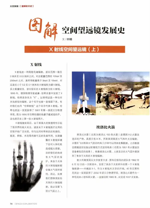
空间望远镜发展史文/叶楠x射线X射线是一种高能电磁辐射,波长范围一般在3纳米至0.03纳米之间,对应能量范围在100eV至200keV之间。
通常将能量高于5keV至40keV、对应波长小于0.2至0.1纳米的X射线称为硬X射线,反之能量较低、波长较长的X射线称为软X射线。
4895年,德国物理学家威廉•伦琴无意中发现了X射线,他将其命名为“X”,以表明这是一种当时未知类型的辐射。
这个名字也被一直保留下来,有时我们也用“伦琴射线”这个名字代表X射线。
伦琴也因这一发现获得了1901年第一届诺贝尔物理学奖。
图为4895年伦琴拍摄的他妻子戴戒指的手,这也是历史上第一张X射线照片。
X射线被发现后,由于其强大的穿透特性引起了医学界的极大关注,诸多关于X射线医疗应用的实验开始广泛出现,但与此同时带来的还有烧伤、脱发、肿胀、水泡等肉眼可见的负面作用。
长期暴露在X射线环境下会对人体机能造成极大损害,还好我们的地球有大气层的保护,来自于天体的X射线辐射都会被大气层所阻挡。
因此,如果我们想探测其他天体的X射线辐射,就必须要飞到大气层之上。
埃洛比火箭埃洛比火箭(左图为埃洛比150型火箭)是德国V-2火箭改造后的产物,高度只有8米,用来探测高层大气和外太空辐射。
火箭在飞出地球大气层后约有几分钟可以用来收集数据,之后数据会跟随返回设备以软着陆方式返回地面(右图为1951年火箭返回设备着陆后的场景)。
依靠埃洛比火箭,人类首次在大气层外探测到了来自于太阳的X射线辐射。
意大利裔美国天文学家里卡多•贾科尼领导的团队在1962年6月42日的一次探测中,发现了来自于太阳系外的第一个X射线辐射源——天蝎座X-4。
作为X射线天文学的开端,40年后贾科尼因这一发现获得了2002年诺贝尔物理学奖。
埃洛比火箭作为一种低成本小型科研火箭,一直服役到4985年,共完成1037次发射。
印度首颗人造卫星4972年,印苏签署协议,苏联以帮助印度发射卫星来换取印度港口的使用权。

45系列轴向柱塞泵45系列开式轴向柱塞泵产品样本45系列开式轴向柱塞泵产品样本版本信息修订历史修订记录表日期 2012年10月 2012年9月 2012年9月 2012年8月 2012年7月 2012年6月 2012年3月 2012年1月 2011年12月 2011年10月页码多页多页多页 14-15, 62 多页 17,23,44,72,92 110 多页 75 多页多页 56 108 多页 45, 50 45 多页 22, 27, 31, 41, 43, 47 34, 28 多页多页 62, 65 58-62 78, 93, 94, 95 32, 74, 75, 92 76 52, 53 27, 50, 72, 89 76 4 多页多页 50 多页 51, 52, 53 修改项目增加电控根据原中文版本及英文版本GO大幅修改多处修正增加补油泵回路,增加S5轴输入轴及辅助安装法兰O型圈尺寸变更删除各排量泵的轴承寿命表删除工作盖板尺寸图添加系统稳定性,20页,型号代码多处更改修改 A2 轴描述多处改变及修改技术规格校订,选型代码校订示意图修改花键啮合尺寸修改通篇多处修改060B最高速度3120,安装法兰修改添加065C, 075C轴承寿命参数多处校订及改变-主要修改多处小修改,添加EJ, EA控制器尺寸去掉L和K型中T2轴选项修改对LS的X口接头深度的警告添加对LS的X口接头深度的警告添加 SAE-C 2螺栓壳体 J型尺寸修改多处小修改,去掉E型S5轴选项示意图修改S2花键宽度修改(仅英制尺寸)示意图修改添加RP 和BP控制的LS设定值必须为20bar 对S2轴-6级,长37.91mm的修改 TOC的修改针对每一型号添加了LS设定范围重新布置F和E型章节,添加排量限制器信息修改负载敏感设定值-增量 bar 去掉G型,添加F型,多处修改修改示意图信息去掉H型,添加J型添加E型添加H型和G型第一次印刷版本 GP GO GN GM GL GK GJ GI GHGG GF GE GD GC GB GA FO FN FM FL FK FJ FI FH FG FG FF FF FE FD FC FB FA E D C B A A45系列开式轴向柱塞泵2011年6月 2011年5月 2011年4月 2011年3月 2011年1月 2010年11月 2010年10月 2009年10月 2009年7月 2009年5月 2009年3月 2008年10月 2008年9月 2008年6月 2008年5月 2008年4月 2008年4月 2008年4月 2008年4月 2008年3月2008年2月2007年11月2007年11月2007年9月2006年11月 2005年8月 2003年4月 2001年5月 1999年5月2012 萨澳-丹佛斯版权所有萨澳-丹佛斯对于其产品样本,手册和其它出版物中可能出现的错误不负任何责任。
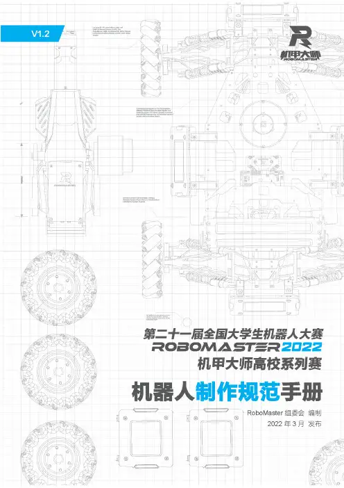
2 © 2022 大疆创新 版权所有阅读提示符号说明 禁止 重要注意事项 操作、使用提示 词汇解释、参考信息前置参考阅读1. 《裁判系统用户手册》2. 裁判系统各模块说明书建议用户首先阅读裁判系统各模块说明书,了解裁判系统各模块的功能以及安装方式,正确安装裁判系统的各模块,再通过《裁判系统用户手册》了解整个裁判系统的功能。
修改日志本手册将在每赛季根据实际情况更新两次。
手册发布后,根据规定日期生效。
日期版本修改记录生效日期 2022.03.29 V1.21. 增加第三方成品模组的限制2. 删除飞镖“R ”标朝上的限制2022.03.28 2022.01.11 V1.11. 明确底盘功率的定义2. 修订机器人整机成品及开源机器人使用规范2022.01.11 2021.10.15V1.0 首次发布 2021.10.15© 2022 大疆创新 版权所有3目录阅读提示 (2)符号说明 (2)前置参考阅读 (2)修改日志 .................................................................................................................................................. 2 1.前言 ................................................................................................................................................ 10 2.技术规范 ........................................................................................................................................ 11 2.1 通用技术规范 .. (11)2.1.1能源 .................................................................................................................................. 11 2.1.2无线电 ............................................................................................................................. 12 2.1.3光学手段 .......................................................................................................................... 12 2.1.4视觉特征 .......................................................................................................................... 13 2.1.5机器人编号 ...................................................................................................................... 13 2.1.6外观设计 .......................................................................................................................... 14 2.1.7发射机构 .......................................................................................................................... 15 2.1.8自定义控制器 .................................................................................................................. 15 2.1.9其它 ................................................................................................................................. 16 2.2 机器人整机成品及开源机器人使用规范 . (17)2.2.1充分再设计 ...................................................................................................................... 17 2.2.2非充分再设计 .................................................................................................................. 18 2.2.3 无效再设计 . (18)2.3 机器人技术规范 (19)2.3.1英雄机器人 ...................................................................................................................... 19 2.3.2工程机器人 ...................................................................................................................... 20 2.3.3步兵机器人 ...................................................................................................................... 22 2.3.4空中机器人 ...................................................................................................................... 24 2.3.5哨兵机器人 ...................................................................................................................... 26 2.3.6飞镖系统 .......................................................................................................................... 27 2.3.7 雷达 ................................................................................................................................. 31 3.裁判系统安装规范 .......................................................................................................................... 33 3.1概述 ........................................................................................................................................ 33 3.2机器人裁判系统配置 ............................................................................................................... 34 3.3 主控模块安装规范 (35)3.3.1 安装步骤 (36)3.3.2安装要求 (37)3.4电源管理模块安装规范 (38)3.4.1安装步骤 (39)3.4.2安装要求 (41)3.5灯条模块安装规范 (43)3.5.1安装步骤 (44)3.5.2安装要求 (45)3.6装甲模块安装规范 (46)3.6.1通用 (48)3.6.2安装步骤 (51)3.6.3安装要求 (56)3.6.4ID编号设置 (58)3.7测速模块安装规范 (59)3.7.1安装步骤 (60)3.7.2安装要求 (65)3.8场地交互模块安装规范 (66)3.8.1安装步骤 (67)3.8.2安装要求 (68)3.8.3场地交互模块卡 (68)3.9相机图传模块(发送端)安装规范 (68)3.9.1安装步骤 (69)3.9.2安装要求 (70)3.10相机图传模块(接收端)安装规范 (70)3.10.1安装要求 (71)3.11定位模块安装规范 (71)3.11.1安装步骤 (72)3.11.2安装要求 (72)3.1217mm荧光弹丸充能装置安装规范 (73)3.12.1安装步骤 (74)3.12.2安装要求 (75)3.12.3自制紫外灯板指导及要求 (76)3.13超级电容管理模块安装规范 (76)3.13.1安装步骤 (76)3.13.2安装要求 (78)附录一17mm 测速模块转接块工程图 (79)4 © 2022 大疆创新版权所有© 2022 大疆创新 版权所有5 附录二 参考图纸 (80)表目录表2-1 控制方式汇总 (12)表2-2 自定义控制器制作参数说明 (15)表2-3 英雄机器人制作参数说明 (19)表2-4 工程机器人制作参数说明 (20)表2-5 步兵机器人制作参数说明 (22)表2-6 空中机器人制作参数说明 (24)表2-7 哨兵机器人制作参数说明 (26)表2-8 飞镖制作参数说明 (28)表2-9 飞镖发射架制作参数说明 (28)表2-10 雷达运算平台端制作参数说明 (31)表2-11 雷达传感器端参数说明 (31)表3-1 裁判系统组成模块 (33)表3-2 机器人裁判系统模块配置 (34)表3-3 电源管理模块接口对照 (42)6 © 2022 大疆创新版权所有© 2022 大疆创新 版权所有7图目录图 2-1 平衡步兵机器人示意图 (23)图 2-2 航行外观灯有效区域 (26)图 2-3 飞镖触发装置示意图 (29)图 2-4 飞镖触发装置遮挡示意图 (30)图 2-5 飞镖触发装置内部空腔遮挡示意图 (30)图 3-1 主控模块示意图 (36)图 3-2 主控模块安装示意图 (36)图 3-3 主控模块连线示意图 (37)图 3-4 主控模块安装位置示意图 (38)图 3-5 电源管理模块示意图 (39)图 3-6 电源管理模块安装示意图 (40)图 3-7 电源管理模块接口示意图 (41)图 3-8 电源管理模块接线示意图 (41)图 3-9 灯条模块示意图 (44)图 3-10 灯条模块安装示意图 (45)图 3-11 灯条模块底部示意图 (45)图 3-12 灯条模块接线示意图 (45)图 3-13 哨兵机器人灯条模块示意图 (46)图 3-14 指定装甲支撑架示意图 (47)图 3-15 小装甲模块示意图 (47)图 3-16 大装甲模块示意图 (48)图 3-17 机器人坐标系示意图 (48)图 3-18 机器人不同底盘形态X 轴示意图 (49)图 3-19 装甲模块受力示意图 (50)图 3-20 机器人保护示意图 (51)图 3-21 底盘预留孔位 (52)图 3-22 装甲支撑架安装示意图 (52)图 3-23 装甲模块安装示意图 (53)图 3-24 装甲模块连线示意图 (53)图 3-25 底盘预留孔位示意图 (54)图 3-26 装甲支撑架安装示意图 (54)图 3-27 装甲模块安装示意图 (55)图 3-28 底盘预留孔位示意图 (55)图3-29 哨兵支撑架安装示意图 (56)图3-30 哨兵装甲安装示意图 (56)图3-31 地面机器人装甲模块ID设置示意图 (59)图3-32 17mm测速模块示意图 (60)图3-33 42mm测速模块示意图 (60)图3-34 17mm枪管示意图 (61)图3-35 测速模块安装示意图 (62)图3-36 17mm转接块零件示意图 (62)图3-37 17mm转接块固定方式示意图 (63)图3-38 17mm短枪管安装示意图 (64)图3-39 42mm枪管示意图 (65)图3-40 测速模块安装规范示意图 (66)图3-41 场地交互模块示意图 (67)图3-42 场地交互模块连线示意图 (67)图3-43 场地交互模块安装示意图 (67)图3-44 场地交互模块卡示意图 (68)图3-45 相机图传模块(发送端)示意图 (69)图3-46 相机图传模块(发送端)安装示意图 (70)图3-47 相机图传模块(接收端)示意图 (71)图3-48 定位模块示意图 (71)图3-49 定位模块安装示意图 (72)图3-50 定位模块连线示意图 (72)图3-51 定位模块安装示意图 (73)图3-52 17mm荧光弹丸充能装置示意图 (74)图3-53 紫外灯板安装示意图 (75)图3-54 电容管理模块接线示意图 (77)8 © 2022 大疆创新版权所有© 2022 大疆创新 版权所有9附录图目录附录图 1 工程机器人装甲贴纸 - 2号 (80)附录图 2 步兵机器人装甲贴纸 - 3号 (80)附录图 3 步兵机器人装甲贴纸 - 4号 (81)附录图 4 步兵机器人装甲贴纸 - 5号 (81)附录图 5 英雄机器人装甲贴纸 - 1号 (82)附录图 6 平衡步兵机器人装甲贴纸 - 3号 (82)附录图 7 平衡步兵机器人装甲贴纸 - 4号 (83)附录图 8 平衡步兵机器人装甲贴纸 - 5号 (83)附录图 9 前哨站装甲贴纸 (84)附录图 10 基地小装甲贴纸 (84)附录图 11 哨兵机器人装甲贴纸 (85)附录图 12 基地大装甲贴纸 (85)1. 前言RoboMaster参赛队伍需自行研发和制作参赛机器人,参赛机器人需满足本文档描述的所有规范,否则无法通过赛前检录。

摘要工业机械手有能模仿人手和手臂的某些动作功能,用固定程序搬运,抓取物体或操作工具的自动操作装置,机械手主要由手部和运动机构组成。
按照搬运或者抓取的物件形状、尺寸、重量、材料和作业环境等的要求的不同,手结构形式有吸附型和夹持型等。
运动机构的功能是使手部完成各种动作:移动、转动等运动来实现规定的动作。
机构的伸缩、升降和旋转等运动方式,称为机械手的自由度。
本设计选用三自由度直角坐标型工业机器人,其自由度为X轴,Y轴和Z轴方向,是通过滚珠丝杠来实现小臂与大臂的伸缩,升降。
而这些动作都是通过在步进电机的带动下进行。
在控制器的作用下,它将执行将工件从一条流水线抓取并运送到另一条流水线这一简单的动作。
本篇论文主要对机械手的传动部分滚珠丝杠与步进电机进行了计算,计算内容主要包括工业机器人的传动机构的设计,以及其机械传动装置的选择。
另外对控制部分的描述主要有PLC的控制方案,接线原理图以及程序流程图等。
关键词:三自由度,直角坐标,PLC,机械手ABSTRACTIndustrial manipulator can imitate some action feature of manpower and arms, with a fixed program handling, automatic operation device for grabbing objects or tools, robotics mainly by hand, and sports organizations. By handling or grabbing the object shape, size, weight, materials and environment requirements are different. The hand structure has absorbed and clamp type. Features of motion mechanism are to complete a variety of movements of hands: mobile, turning movements to implement the provisions of the action. Institutions such as stretch lift and rotate the movement, known as freedom of manipulator. The design selection of three - degree-of-freedom Cartesian - industrial robot, its degrees of freedom for the X axis, Y axis and Z axis direction is achieved by ball screw arm and boom extension lift. These actions are driven by stepping motor. Under the action of the Controller, it will perform the work from one line to grab and shipped to another line of this simple action. This paper mainly on robotic stepping motor drive ball screws and calculation, the calculation includes design of transmission mechanism of industrial robots, as well as its selection of mechanical transmission device. In addition to the Control section describes the main PLC Control Program, wiring schematics, and programs such as flowchart.Key words: three degrees of freedom, Cartesian coordinates, PLC, manipulator目录1 绪论 (1)1.1课题来源 (1)1.2课题目的、意义 (1)1.3国内外发展基本情况 (1)2 工业机械手的总体设计 (3)2.1机械手的组成 (3)2.2工业机械手的设计分析 (4)2.3总体设计方案 (4)3.机械手的机械系统设计 (8)3.1机械手手爪设计 (8)3.2机械手传动部分设计 (15)3.3机械手基座部分设计 (21)3.4轴承的选取 (28)4 PLC控制系统设计 (29)4.1可编程序控制器的选择及工作过程 (29)4.2PLC控制系统 (30)5 结论 (36)参考文献 (37)致谢 (38)1 绪论1.1 课题来源本课题来自于企业项目。
ZEMAX葵花宝典1(入门篇)目录例子1 单透镜(Singlet) .............................................................. .............................................. 5 1.1 单透镜 ..................................................................... ....................................................... 5 1.2 设罝系统孔径 ..................................................................... ............................................ 5 1.3 设罝视场角 ..................................................................... ................................................ 7 1.4 设罝波长...................................................................... ................................................... 7 1.5 键入透镜资料 ..................................................................... ............................................ 8 1.6 设罝透镜参数 ..................................................................... ............................................ 9 1.7 评估系统性能 ..................................................................... ............................................ 9 1.8 使用解 ..................................................................... ..................................................... 10 1.9 设罝优化...................................................................... ................................................. 11 1.10 建立绩效函数 ..................................................................... ........................................ 12 1.11 增加限制条件 ..................................................................... ........................................ 13 1.12 运行优化 ..................................................................... ................................................ 13 1.13 光线扇形图 ..................................................................... ............................................ 14 1.14 二维设计图 ..................................................................... ............................................ 14 1.15 弥散斑 ..................................................................... ................................................... 15 1.16 光程差扇形图 ..................................................................... ........................................ 16 1.17 进一步分析 ..................................................................... ............................................ 17 例子2 座标变换(CoordinateBreaks) ................................................................ .................... 18 2.1 座标变换...................................................................... ................................................. 18 2.2 顺序旗标...................................................................... ................................................. 18 2.3 座标变换的应用 ........................................................................................................... 19 2.4 工具,转折面镜sahaja ................................................................. ............................... 19 2.5 例子,转折面镜 ..................................................................... ...................................... 20 2.6 新增转折面镜 ..................................................................... .......................................... 20 2.7 修正透镜资料编辑器...................................................................... .............................. 21 2.8 删除转折面镜 ..................................................................... .......................................... 22 2.9 倾斜与离轴 ..................................................................... .............................................. 23 2.10 工具,倾斜与离轴 ..................................................................... ................................ 23 2.11 例子,倾斜与离轴 ..................................................................... ................................ 24 2.12 处理倾斜与离轴 ..................................................................... .................................... 24 2.13 设罝倾斜与离轴 ..................................................................... .................................... 25 例子3 牛顿式望远镜 (Newtonian Telescope) ............................................................. .. (26)1 / 873.1 牛顿式望远镜 ..................................................................... .......................................... 26 3.2 孔径、单位、视场角及波长 ..................................................................... ................. 26 3.3 键入透镜资料 ..................................................................... .......................................... 27 3.4 评估系统性能 ..................................................................... .......................................... 28 3.5 定义抛物面 ..................................................................... .............................................. 29 3.6 抛物型反射罩 ..................................................................... .......................................... 29 3.7 点扩散函数 ..................................................................... .............................................. 30 3.8 挡板 ..................................................................... ......................................................... 30 3.9 增加转折面镜 ..................................................................... .......................................... 31 3.10 座标变换 ..................................................................... ................................................ 33 3.11 设罝挡板 ..................................................................... ................................................ 33 3.12 挡板效果 ..................................................................... ................................................ 34 例子4 消色差单透镜(AchromaticSinglet) ............................................................... ............. 36 4.1 消色差单透镜 ..................................................................... .......................................... 36 4.2 标准单透镜 ..................................................................... .............................................. 37 4.3 新增衍射表面 ..................................................................... .......................................... 38 4.4 设罝衍射参数 ..................................................................... .......................................... 39 4.5 评估系统性能 ..................................................................... .......................................... 40 4.6 相位属性分析 ..................................................................... .......................................... 41 例子5 变焦透镜 (Zoom Lens) .................................................................. .............................. 42 5.1 变焦透镜...................................................................... ................................................. 42 5.2 设罝系统参数 ..................................................................... .......................................... 42 5.3 初始透镜参数 ............................................................................................................... 43 5.4 设罝视场角 ..................................................................... .............................................. 44 5.5 设罝波长...................................................................... ................................................. 44 5.6 定义多组态透镜 ..................................................................... ...................................... 45 5.7 键入多组态参数 ..................................................................... ...................................... 46 5.8 设罝多组态变数 ..................................................................... ...................................... 46 5.9 建立多组态绩效函数...................................................................... .............................. 47 5.10 增加限制条件 ..................................................................... ........................................ 48 5.11 设罝透镜尺寸 ..................................................................... ........................................ 48 5.12 运行优化 ..................................................................... ................................................ 49 5.13 评估系统性能 ..................................................................... ........................................ 50 例子6 公差(Tolerancing) .......................................................... ............................................. 51 6.1 概论 .............................................................................................................................. 51 6.2 公差 ..................................................................... (52)2 / 876.3 误差来源...................................................................... ................................................. 52 6.4 设罝公差...................................................................... ................................................. 53 6.5 公差操作数 ..................................................................... .............................................. 53 6.6 双透镜的公差分析 ..................................................................... .................................. 54 6.7 制造与组装公差 ..................................................................... ...................................... 55 6.8 误差描述...................................................................... ................................................. 56 6.9 灵敏度分析 ..................................................................... .............................................. 57 6.10 初步公差分析 ..................................................................... ........................................ 57 6.11 公差分析结果 ..................................................................... ........................................ 58 6.12 统计分析 ..................................................................................................................... 58 6.13 反灵敏度分析 ..................................................................... ........................................ 59 6.14 个别分析视场角/组态 ..................................................................... ........................... 60 6.15 限制公差范围 ..................................................................... ........................................ 60 6.16 设罝限制条件 ..................................................................... ........................................ 61 6.17 修正公差范围 ..................................................................... ........................................ 61 6.18 蒙地卡罗分析 ..................................................................... ........................................ 62 6.19 蒙地卡罗统计 ..................................................................... ........................................ 62 6.20 进一步分析 ..................................................................... ............................................ 63 例子7 混合式非序列 (NSC withPorts) ................................................................. ................. 63 7.1 混合式非序列 ..................................................................... .......................................... 63 7.2 例子,混合式非序列...................................................................... .............................. 64 7.3 出口埠 ..................................................................... ..................................................... 67 7.4非序列组件 ..................................................................... ............................................... 68 7.5 对象属性...................................................................... ................................................. 68 7.6 非序列性透镜对象 ..................................................................... .................................. 69 7.7 复制对象...................................................................... ................................................. 70 7.8 定义多焦透镜 ..................................................................... .......................................... 70 7.9 表面折射...................................................................... ................................................. 70 7.10 空气透镜 ..................................................................... ................................................ 71 7.11 调整焦距参数 ..................................................................... ........................................ 72 7.12 多焦透镜 ..................................................................... ................................................ 72 7.13 运行优化 ..................................................................... ................................................ 73 7.14 带状优化 ..................................................................... ................................................ 74 7.15 目标局部 ..................................................................... ................................................ 76 7.16 光线目标 ..................................................................... ................................................ 77 7.17 系统性能 ..................................................................... ................................................ 78 7.18 运行影像分析性能之优化 ..................................................................... ..................... 78 7.19 设罝变数 ..................................................................... (79)3 / 877.20 最终设计 ..................................................................... ................................................ 80 例子8 物理光学传播(Physical OpticsPropagation) ........................................................... ... 81 8.1 物理光学传播 ..................................................................... .......................................... 81 8.2 定义光线...................................................................... ................................................. 83 8.3 设罝显示参数 ..................................................................... .......................................... 85 8.4 一阶局部...................................................................... ................................................. 85 8.5 其它局部...................................................................... ................................................. 86 8.6 辐射照度分布 ..................................................................... (86)4 / 87例子1 单透镜 (Singlet)1.1 单透镜这个例子是学习如何在ZEMAX里键入资料,包括设罝系统孔径(System Aperture)、透镜单位(Lens Units)、以及波长范围(Wavelength Range),并且进行优化。
QQ3 0.8玛瑞利AMT系统最新电路图安徽奇瑞汽车销售有限公司售后服务部目录一、读图说明 (1)1、电路图说明 (1)2、电器盒说明 (2)2.1、前舱继电器盒 (2)2.2、仪表台继电器盒 (3)二、各电路系统控制原理图 (4)1、起动充电系统 (4)2、发动机控制单元(ECU)、油泵 (5)3、仪表 (6)4、音响系统、点烟器 (7)5、ABS系统 (8)6、气囊和安全带预紧器 (9)7、车身控制模块、后行李厢灯、顶灯 (10)8、喇叭、电动后视镜、后除霜 (11)9、鼓风机、空调、电子风扇 (12)10、雨刮洗涤系统 (13)11、报警灯、转向灯 (14)12、大灯、小灯、雾灯 (15)13、诊断口 (16)14、EPS、倒车灯 (17)15、变速箱控制单元 (18)一、读图说明1、电路图说明该电路图是奇瑞QQ3 0.8AMT玛瑞利系统整车电路图。
与以前的QQ3整车电路相比,多了安全带预涨紧器、保险丝NO34、NO35、NO36、NO37、NO38、记忆保险丝等,其中记忆保险丝是为了减少静态电流。
详情请见以下电路图。
2、电器盒说明2.1、前舱继电器盒2.2、仪表台继电器盒电器盒启动继电器闪光继电器雨刮继电器油泵继电器电器盒A对插件二、各电路系统控制原理图1、起动充电系统2、发动机控制单元(ECU)、油泵3、仪表4、音响系统、点烟器5、ABS系统6、气囊和安全带预紧器30(B+)30a(B+)30(B+)7、车身控制模块、后行李厢灯、顶灯8、喇叭、电动后视镜、后除霜9、鼓风机、空调、电子风扇10、雨刮洗涤系统11、报警灯、转向灯12、大灯、小灯、雾灯13、诊断口14、EPS、倒车灯15、变速箱控制单元。
DCSMi-8MTV2⽶8直升机中⽂飞⾏⼿册驾驶舱系统和控制驾驶舱布局55. 驾驶舱系统和控制驾驶舱包括带各种系统和设备的控制⾯板(驾驶舱布局)、飞⾏控制、动⼒装置和直升机系统控制和指⽰器、飞⾏数据和导航系统控制和指⽰器。
直升机驾驶舱系统和控制套件提供:a)在视觉或仪器⽓象条件下的昼夜飞⾏控制和导航;b)发动机、变速器和飞⾏性能的控制。
c)所有直升机系统的控制。
DCS提供弹出“提⽰”,以识别所有交互式驾驶舱控制/开关,以便于熟悉直升机系统。
要查看特定控制/开关的提⽰,只需将⿏标悬停在驾驶舱中。
可以在选项菜单中启⽤/禁⽤弹出提⽰。
在模拟中,可以使⽤⿏标执⾏以下操作:-左键单击可启⽤开关/按钮;-右击或左击操作多位置开关;-旋转⿏标滚轮或单击⿏标左键,按住并拖动⿏标以旋转开关/转盘。
当⿏标光标放在交互式驾驶舱控件上时,黄⾊⼗字图标将颜⾊更改为绿⾊,以指⽰控件可单击,并更改形状以指⽰控件是离散型还是旋转型。
所有⿏标可点击的控件都提供了⼀个键盘快捷键,可以在“输⼊选项”菜单中找到。
本⼿册中还提供了蓝⾊键盘快捷键。
5.1.驾驶舱布局图5.1.驾驶舱布局1.左侧控制台2.左三⾓板3.⽤于飞⾏员的SPU-7控制箱内部通信装置4.发动机的燃油切断杆(燃油切断触发器)5.引航瞄准具6.左顶控制台7.左断路器控制台8.中控台9.右断路器控制台10.右顶置控制台11.⽤于副驾驶的SPU-7控制箱内部通信装置12.右三⾓板13.右侧控制台14.右后控制台15.副驾驶武器控制⾯板16.室外温度计17.驾驶舱风扇18..左仪表板19.右仪表板20.ЭСБР-3П/А(ESBR-3P/A)电⽓释放控制箱21.中央控制台22.副驾驶瞄准具ОПБ-1р(OPB-1R)-轰炸瞄准具,未建模23.右侧辅助⾯板24.转⼦制动杆25.油门⼿柄26.集控⼿柄27.防扭矩踏板28.空速管选择器29.循环控制棒30.G-负载指⽰器31.磁性CompasКИ-13(KI-13)5.1.1.左仪表板(飞⾏员)图5.2.左仪表板(飞⾏员)1.飞⾏员着陆/搜索和滑⾏灯控制2.УР-117М(UR-117M)发动机压⼒⽆线电(EPR)指⽰器3.ИП-21(IP-21)主转⼦变桨⾓度指⽰器4.ИТЭ-2Т(ITE-2t)双指针发动机转速表指⽰器5.ИТЭ-1Т(ITE-1T)主转⼦转速表指⽰器6.雷达⾼度表开关7.УС-450К(US-450K)空速指⽰器8.УВ-5m(UV-5m)雷达⾼度表指⽰器9.ВД-10ВК(VD-10VK)压⼒⾼度表指⽰器10.ОПБ-1Р(OPB-1R)炸弹瞄准航向指⽰器11.АРКСВ-УКВ(ADF HF-VHF)开关12.УГР-4УК(UGR-4UK)定向陀螺仪13.АГБ-3К(AGB-3K)姿态指⽰器14.悬停和低速控制指⽰灯15.ВР-30МК(VR-30MK)垂直速度指⽰器16.UV-26⼿动⽕炬分散按钮对策17.信号器(灯)18.ЭУП-53(EUP-53)转向指⽰器19.СЕТЕПИТ.ОТАКК”(“使⽤中的电池”)灯(上图)和“ОТАКАЗ6201”(“6201故障”)(下图)20.信号器(灯)21.2个УТ-6К(2UT-6K)废⽓温度指⽰器22.信号器(灯)23.空速管选择器(17)警⽰灯:1.主齿轮箱中的碎屑2.中间齿轮箱中的碎屑3.尾桨齿轮箱中的碎屑(20)警⽰灯:1.左(右)发动机⾃由涡轮超速2.左(右)发动机机油压⼒低3.电⼦控制左(右)发动机关闭4. 紧急电源(ЧР–ЧрезвычайныйРежим) 左(右)机应急电源(22) 警⽰灯:1.左(右)发动机油中的碎屑2.燃油滤清器堵塞左(右)发动机3.左(右)发动机异常振动4.左(右)发动机偏移极限振动5.不使⽤灯6.⽕灾5.1.2.右仪表板(副驾驶)图5.3.右仪表板(副驾驶)1.УС-450К(US-450K)空速指⽰器2.ВД-10ВК(VD-10VK)压⼒⾼度表指⽰器3.АГБ-3К(AGB-3K)姿态指⽰器4.УГР-4УК(UGR-4UK)定向陀螺仪5.ВР-30МК(VR-30MK)垂直速度指⽰器6.“ДИСОТКАЗАЛ”多普勒系统故障信号机7.ИТЭ-1Т(ITE-1T)主转⼦转速表指⽰器8.ИТЭ-2Т(ITE-2t)双指针发动机转速表指⽰器9.副驾驶着陆/搜索灯开关10.ТВ-1(TV-1)客舱温度指⽰器11.ДИС-15(DISS-15)多普勒系统坐标指⽰器12.ДИС-15(DISS-15)多普勒系统地⾯速度和漂移指⽰器13.БЭ-09К(BE-09K)燃油量指⽰器14.低燃油(270升)信号器15.П-8УК(P-8UK)燃油表开关А完成С-1(ACHS-1)CLO5.1.3.中⼼控制台图5.4.中⼼控制台1.УИЗ-6 (UIZ-6) 主输送油温、中间体和尾转⼦油压指⽰器2.ТУЭ-48 (TUE-48)主输油温度指⽰器3.УИЗ-3 (UIZ-3)左发动机油压和温度指⽰器4.УИЗ-3 (UIZ-3)右发动机油压和温度指⽰器5.Р-863 (R-863)甚⾼频⽆线电⼿动/预设选择器6.Р-863 (R-863)甚⾼频⽆线电控制⼩组7.Р-863 (R-863)甚⾼频⽆线电频率选择板8.发动机控制板9.灯测试与电⽓系统备⽤开关10.АП-34Б (AP-34B)⾃动驾驶盘11.БУ-32-1 (BU-32-1) 俯仰限制系统的控制单元СПУУ-52 (SPUU-52)12.ИН-4 (IN-4) ⾃动飞⾏控制系统的三维指⽰器5.1.4.左侧控制台图5.5.左侧控制台1.左侧组1/2红⾊照明调光器2.“РТЛЕВРАБОТАЕТ”“РТПРАВРАБОТАЕТ”左侧/右侧发动机温度调节器操作信号器3.ЭП-662(EP-662)信号灯控制⾯板4. “САРППРАБОТАЕТ”飞⾏数据记录器(FDR)操作信号机5.МВУ-10К(MVU-10K)⽓动系统⽓压计6.РИ-65Б(RI-65B)语⾳报警系统远程控制⾯板7.МА-60К (MA-60K) ⽤于起落架轮刹车系统的МА-60К(MA-60K)⽓压计8.“装置6201”控制⾯板484(IFF应答器)9.“装置6201”控制⾯板485(IFF应答器)10.П-503Б(P-503B)驾驶舱语⾳记录器(CVR)控制⾯板11.“ВК__ИЗАПАСНО_”(“设置备⽤”)信号机12.外部货物⾃动释放开关13.“СТВОРКИОТКРЫТЫ”(“开门”)信号机14.“ЗАМОКОТКРЫТ”(“卸扣打开”)信号机15.“СИРЕНАВКЛЮЧЕНА”(“喇叭开启”)信号机16.⽓喇叭按钮17.代码导航灯按钮18.FDR电源开关19.左/右发动机温度调节器测试按钮20.地⾯和空⽓测试按钮21.发动机振动指⽰器测试按钮。