SEMI C3[1].55-0200 STANDARD FOR SILANE (SiH4), BULK
- 格式:pdf
- 大小:164.19 KB
- 文档页数:6

产品名称:SiO2微粒子标准溶液纳米级别二氧化硅SiO2标准粒子晶圆表面用二氧化硅纳米二氧化硅™尺寸标准MSP Corporation 的NanoSilica™Size Standards 是SiO2颗粒的浓缩水悬浮液,具有高度均匀的尺寸分布。
这些粒径标准目前提供的标称尺寸范围为15 至200 nm,非常适合为下一代晶圆和光掩模检测系统生产高质量校准标准。
虽然MSP 23000NPT 系列和2300G3 系列粒子沉积系统为表面缺陷校准标准的生产提供了最佳结果,但较旧的MSP 系统和其他制造商的系统也适用于纳米二氧化硅尺寸标准。
特征+ 极其均匀的尺寸分布我们的纳米二氧化硅尺寸标准采用获得专利的SiO2合成工艺开发,其尺寸分布比市售的PSL 球更窄。
+ 使用SI 可追溯性测量的峰直径允许产量提高和计量小组根据ISO 9000 标准和SEMI 指南建立其检查和缺陷审查方法的可追溯性。
+ 受到强烈DUV 辐射时稳定MSP 的SiO2颗粒在暴露于DUV 辐射时不会降解,这与PSL 球体不同,PSL 球体的尺寸会减小。
+ 易于使用NanoSilica 颗粒悬浮液在滴管瓶中提供,以便在您的应用中混合具有适当数量浓度的悬浮液时使用方便。
+ 高粒子浓度一些应用需要高浓度。
MSP 的颗粒浓度是业内最高的之一。
+ 轻松辨别模态(峰值)直径+ 避免由于平均和峰值直径值之间的差异而导致的差异+ 制备适用于效率相对较高或较低的气溶胶产生装置的稀释悬浮液+ 为最先进的检测工具创建持久的校准标准+ 消耗更少的材料;存钱+ 随附校准和可追溯性证书以及带有处理和处置说明的安全数据表(SDS)2相对半高宽(半高全宽);FWHM 除以模态直径。
NanoSilica™ 微粒子标准溶液是由MSP Corporation制作的高度均匀尺寸SiO2微粒子浓缩水溶液,微粒子尺寸从18nm到200nm都可选择,是市面上最理想、高质量的校正标准,适用于最新一代的晶圆表面污染/缺陷检查系统及光罩检查系统。
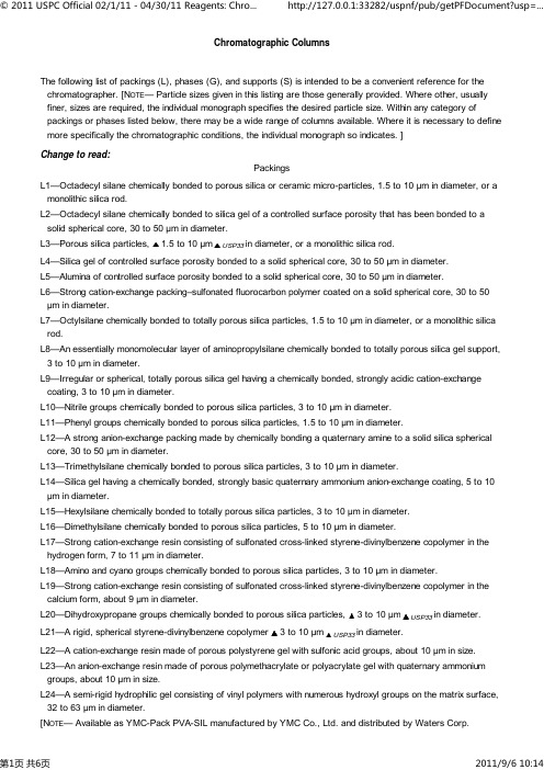
Chromatographic ColumnsThe following list of packings (L), phases (G), and supports (S) is intended to be a convenient reference for the chromatographer. [N OTE— Particle sizes given in this listing are those generally provided. Where other, usually finer, sizes are required, the individual monograph specifies the desired particle size. Within any category of packings or phases listed below, there may be a wide range of columns available. Where it is necessary to define more specifically the chromatographic conditions, the individual monograph so indicates. ]Change to read:PackingsL1—Octadecyl silane chemically bonded to porous silica or ceramic micro-particles, 1.5 to 10 µm in diameter, or a monolithic silica rod.L2—Octadecyl silane chemically bonded to silica gel of a controlled surface porosity that has been bonded to a solid spherical core, 30 to 50 µm in diameter.L3—Porous silica particles, 1.5 to 10 µm USP33in diameter, or a monolithic silica rod.L4—Silica gel of controlled surface porosity bonded to a solid spherical core, 30 to 50 µm in diameter.L5—Alumina of controlled surface porosity bonded to a solid spherical core, 30 to 50 µm in diameter.L6—Strong cation-exchange packing–sulfonated fluorocarbon polymer coated on a solid spherical core, 30 to 50µm in diameter.L7—Octylsilane chemically bonded to totally porous silica particles, 1.5 to 10 µm in diameter, or a monolithic silica rod.L8—An essentially monomolecular layer of aminopropylsilane chemically bonded to totally porous silica gel support, 3 to 10 µm in diameter.L9—Irregular or spherical, totally porous silica gel having a chemically bonded, strongly acidic cation-exchange coating, 3 to 10 µm in diameter.L10—Nitrile groups chemically bonded to porous silica particles, 3 to 10 µm in diameter.L11—Phenyl groups chemically bonded to porous silica particles, 1.5 to 10 µm in diameter.L12—A strong anion-exchange packing made by chemically bonding a quaternary amine to a solid silica spherical core, 30 to 50 µm in diameter.L13—Trimethylsilane chemically bonded to porous silica particles, 3 to 10 µm in diameter.L14—Silica gel having a chemically bonded, strongly basic quaternary ammonium anion-exchange coating, 5 to 10µm in diameter.L15—Hexylsilane chemically bonded to totally porous silica particles, 3 to 10 µm in diameter.L16—Dimethylsilane chemically bonded to porous silica particles, 5 to 10 µm in diameter.L17—Strong cation-exchange resin consisting of sulfonated cross-linked styrene-divinylbenzene copolymer in the hydrogen form, 7 to 11 µm in diameter.L18—Amino and cyano groups chemically bonded to porous silica particles, 3 to 10 µm in diameter.L19—Strong cation-exchange resin consisting of sulfonated cross-linked styrene-divinylbenzene copolymer in the calcium form, about 9 µm in diameter.L20—Dihydroxypropane groups chemically bonded to porous silica particles, 3 to 10 µm USP33in diameter.L21—A rigid, spherical styrene-divinylbenzene copolymer 3 to 10 µmUSP33in diameter.L22—A cation-exchange resin made of porous polystyrene gel with sulfonic acid groups, about 10 µm in size.L23—An anion-exchange resin made of porous polymethacrylate or polyacrylate gel with quaternary ammonium groups, about 10 µm in size.L24—A semi-rigid hydrophilic gel consisting of vinyl polymers with numerous hydroxyl groups on the matrix surface, 32 to 63 µm in diameter.[N OTE— Available as YMC-Pack PVA-SIL manufactured by YMC Co., Ltd. and distributed by Waters Corp.L26—Butyl silane chemically bonded to totally porous silica particles, 1.5 USP33L28—A multifunctional support, which consists of a high purity, 100 , spherical silica substrate that has beenL29—Gamma alumina, reverse-phase, low carbon percentage by weight, alumina-based polybutadiene spherical particles, 5 µm in diameter with a pore volume of 80 .L31—A hydroxide-selective, strong anion-exchange resin-quaternary amine bonded on latex particles attached to a core of 8.5-µm macroporous particles having a pore size of 2000 and consisting of ethylvinylbenzene cross-— Available as TSK-GEL G4000SWxl USP33L35—A zirconium-stabilized spherical silica packing with a hydrophilic (diol-type) molecular monolayer bonded phase having a pore size of 150 .L40—Cellulose tris-3,5-dimethylphenylcarbamate coated porous silica particles, 5 to 20 µm in diameter.L41—Immobilized 1L44—A multifunctional support, which consists of a high purity, 60 , spherical silica substrate that has beenL46—Polystyrene/divinylbenzene substrate agglomerated with quaternary amine functionalized latex beads, about 9 to 11 µm USP33L48—Sulfonated, cross-linked polystyrene with an outer layer of submicron, porous, anion-exchange microbeads, 10 to 15 µm USP33— Available as Zirchrom PBD from . USP33— Available as TSK-GEL IC-Cation-SW USP33L57—A chiral-recognition protein, ovomucoid, chemically bonded to silica particles, about 5 µm in diameter, with a pore size of 120 .— Available as TSK-GEL G3000SWxl USP33mm SW from Tosoh Bioscience USP33— Available as Supelcosil LC-ABZ USP33L61—A hydroxide selective strong anion-exchange resin consisting of a highly cross-linked core of 13-µmmicroporous particles having a pore size less than 10 units and consisting of ethylvinylbenzene cross-linked with 55% divinylbenzene with a latex coating composed of 85-nm diameter microbeads bonded with alkanol quaternaryL62—C30 silane bonded phase on a fully porous spherical silica, 3 to 15 µm in diameter.L63—Glycopeptide teicoplanin linked through multiple covalent bonds to a 100- units spherical silica.L67—Porous vinyl alcohol copolymer with a C18 alkyl group attached to the hydroxyl group of the polymer, 2 to 10 µm in diameter. USP33L71—A rigid, spherical polymetacrylate, 4 to 6 µm in diameter.. ] USP33L74—a strong anion-exchange resin consisting of a highly cross-linked core of 7- µm macroporous particles having a 100- average pore size and consisting of ethylvinylbenzene cross-linked with 55% divinylbenzene and). ] (RB 1-Mar-2010)calcining above 900. The siliceous earth is acid-washed, then water-washed until neutral, but not base-washed. The siliceous earth may be silanized by treating with an agent such as dimethyldichlorosilane [NS1C—A support prepared from crushed firebrick and calcined or burned with a clay binder above 900 with。
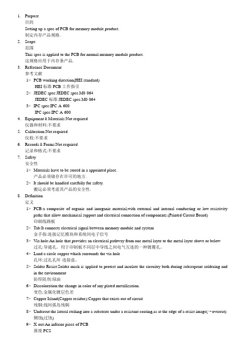
1.Purpose目的Setting up a spec of PCB for memory module product.制定内存产品规格.2.Scope范围This spec is applied to the PCB for normal memory module product.这规格应用于内存条产品.3.Reference Document参考文献1>PCB working direction(HEI standard)HEI标准PCB工作指引2>JEDEC spec:JEDEC spec.M0-064JEDEC标准:JEDEC spec.M0-0643>IPC spec:IPC-A-600IPC spec:IPC-A-6004.Equipment & Materials:Not required仪器和材料:不要求5.Calibration:Not required仪校:不要求6.Records & Forms:Not required记录和格式:不要求7.Safety安全性1>Materials have to be stored in a appointed place.产品必须储存在许可的地方.2>It should be handled carefully for safety.搬运必须考虑其产品的安全性.8.Definition定义1>PCB:a composite of organic and inorganic material,with external and internal conducting or low-resistivitypaths that allow mechanical support and electrical connection of components.(Printed Circuit Board)印刷线路板2>Tab:It connects electrical signal between memory module and system金手指:连接记忆模块和系统间电子信号3>Via hole:An hole that provides an electrical pathway from one metal layer to the metal layer above or below过孔:导通孔。
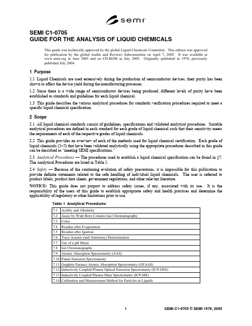
SEMI C1-0705GUIDE FOR THE ANALYSIS OF LIQUID CHEMICALSThis guide was technically approved by the global Liquid Chemicals Committee. This edition was approvedfor publication by the global Audits and Reviews Subcommittee on April 7, 2005. It was available at in June 2005 and on CD-ROM in July 2005. Originally published in 1978; previouslypublished July 2004.1 Purpose1.1 Liquid Chemicals are used extensively during the production of semiconductor devices; their purity has been shown to affect the device yield during the manufacturing processes.1.2 Since there is a wide range of semiconductor devices being produced, different levels of purity have been established as standards and guidelines for each liquid chemical.1.3 This guide describes the various analytical procedures for standards verification procedures required to meet a specific liquid chemical specification.2 Scope2.1 All liquid chemical standards consist of guidelines, specifications and validated analytical procedures. Suitable analytical procedures are defined in each standard for each grade of liquid chemical such that their sensitivity meets the requirements of each of the respective grades of liquid chemicals.2.2 This guide provides an overview of each of the methods used for liquid chemical certification. Each grade of liquid chemicals (1–5) that have been validated analytically using the appropriate procedures described in this guide can be described as “meeting SEMI specifications.”2.3 Analytical Procedures — The procedures used to establish a liquid chemical specification can be found in §7. The Analytical Procedures are listed in Table 1.2.4 Safety — Because of the continuing evolution of safety precautions, it is impossible for this publication to provide definite statements related to the safe handling of individual liquid chemicals. The user is referred to product labels, product data sheets, government regulations, and other relevant literature.NOTICE: This guide does not purport to address safety issues, if any, associated with its use. It is the responsibility of the users of this guide to establish appropriate safety and health practices and determine the applicability of regulatory or other limitations prior to use.Table 1 Analytical Procedures7.1 Acidity and Alkalinity7.2 Assay by Wide Bore Column Gas Chromatography7.3 Color7.4 Residue after Evaporation7.5 Residue after Ignition7.6 Trace Arsenic (and Antimony) Determination7.7 Use of a pH Meter7.8 Ion Chromatography7.9 Atomic Absorption Spectrometry (AAS)7.10 Flame Emission Spectrometry7.11 Graphite Furnace Atomic Absorption Spectrometry (GFAAS)7.12 Inductively Coupled Plasma Optical Emission Spectrometry (ICP-OES)7.13 Inductively Coupled Plasma Mass Spectrometry (ICP-MS)7.14 Calibration and Measurement Method for Particles in Liquids3 Referenced Standards and Documents3.1 ASTM Standards1ASTM D5127 — Standard Guide for Ultra Pure Water Used in the Electronics and Semiconductor IndustryASTM E203 — Standard Test Method for Water Using Volumetric Karl Fischer TitrationNOTICE: Unless otherwise indicated, all documents cited shall be the latest published versions.4 Requirements4.1 Abbreviations and Signs — In this guide abbreviations and signs used shall be restricted to those used in publications of the American Chemical Society (ACS)2.4.2 Accuracy and Tolerances in Measurements — In a test procedure, unless otherwise specified, the accuracy required in the amount of sample taken shall be understood to be within 2.0% of the stated amount, whether a weight or a volume. Where a dilution is performed to a stated volume or a stated volume of a solution is taken, that volume shall be within 2.0% of the stated amount.4.3 Acidity and Alkalinity — A test for acidity or alkalinity, or both, of liquid chemicals may be specified. (See Acidity and Alkalinity in ¶7.1.)4.4 Analytical Blank — Where a “blank” is specified to be run, unless otherwise stated, it shall be performed with the same quantities of the same reagents and in a manner identical to that followed with the sample portion under test, but with the material itself omitted.4.5 Apparatus — Apparatus, unless otherwise qualified, shall be that commonly employed in the conduct of the relevant test.4.6 Atomic and Formula Weights — Atomic weights (i.e. atomic masses) used shall be those of the latest publication of The International Union of Pure and Applied Chemistry (IUPAC)3. Formula weights shall be calculated from a given empirical (molecular) formula by addition of the stated multiples of the atomic weights. Unless otherwise stated, formula weights shall be rounded to 2 significant figures to the right of the decimal point (see Rounding of Numbers, ¶4.17).4.7 Comparison of Analytical Results with Specification Limits — In the comparison of an analytical result for a test with the numerical limit associated with the specification, the result shall be rounded to the number of significant figures indicated for that limit. (See Rounding of Numbers, ¶4.17.) Consequently, a specification stated at 96% minimum will be met by a result as small as 95.5%, and that stated as 96.0% minimum will be met by a result as small as 95.95%. A specification of 0.1% maximum will be met by a result as large as 0.149%, and that of 0.10% maximum by a result as large as 0.105%. In those specifications given with no digit following the decimal point, such as 10 ng/mL maximum, a test result as large as 10.5 ng/mL will meet the specification. This use of a decimal point is made to clarify the difference between converting 0.01 mg/mL to 10 ng/mL and converting 0.010 mg/mL to 10. ng/mL.44.8 Density — The density of a liquid shall be determined for the compound in air at 25°C and be expressed in grams/milliliter (g/mL). Where the specific gravity, with respect to water, is determined, it shall be expressed as density by the use of tabular values for the density of water at the relevant temperature(s).4.9 Desiccator — A desiccator shall imply a tightly closed container charged with a suitable desiccant (commonly calcium chloride or sulfate) that allows an atmosphere of low humidity to be maintained.1 American Society for Testing and Materials, 100 Barr Harbor Drive, West Conshohocken, Pennsylvania 19428-2959, USA. Telephone:610.832.9585, Fax: 610.832.9555, Website: 2 /ONLINE/standards.html, American Chemical Society, 1155 Sixteenth Street, NW, Washington DC, 20036, Phone: 202-872-4600, Fax: 202-872-4615, Website: 3 The International Union of Pure and Applied Chemistry, PO Box 13757, Research Triangle Park, NC 27709-3757, USA, Website:4 H.A. Flachka, A.J. Barnard Jr., P.E. Sturrock. Quantitative Analytical Chemistry, Willard Grant Press, 2nd ed., 1980, p 4.4.10 Drying or Igniting to Constant Weight — A statement “dried to a constant weight” or “ignited to a constant weight” shall imply that two separate weighings differ by no more than ± 0.4 mg (unless otherwise specified), where the second weighing follows a second drying (for one hour (unless otherwise stated) or ignition for 15 minutes (unless otherwise stated), respectively.4.11 Expression of Content and Concentration — Unless otherwise stated, a specification limit and experimental results related to it shall be expressed in units of weight by weight. The concentration of a solution of a test reagent shall be expressed either in molarity or normality or as percent weight by volume. A redox normality value shall always be followed, parenthetically, by the relevant molarity. In the approximate dilution of reagents, a parenthetical expression of two numbers with an intervening “plus” sign shall imply that the relative volume of the stated reagent given by the first number shall be admixed with the relative volume of water given by the second number. Thus, “dilute” sulfuric acid (1 + 3) directs that one volume of reagent grade sulfuric acid be added to 3 volumes of water and the mixture stirred to form a uniform solution.4.12 Filtration — A statement to “filter,” unless qualified, shall imply filtration through suitable filter paper until the filtrate is clear.4.13 Physical Properties — Physical properties shall not usually be employed for specification purposes; for information, however, representative values for a particular liquid chemical, as supplied, may be included in the standard for that liquid chemical. Where relevant, physical properties shall be specified for 25°C.4.14 Reagent Chemicals — Unless otherwise stated, reagents to be used in tests shall conform to the minimum standards of quality set forth in the current edition of Reagent Chemicals, published by the American Chemical Society5.4.15 Residue after Evaporation — A “residue after evaporation” test may be used in the assessment of liquid chemicals. (See Determination of Residue after Evaporation, ¶7.4.)4.16 Residue after Ignition — A “residue after ignition” test serves to assess the amount of nonvolatile inorganic matter present in a sample. (See Determination of Residue after Ignition, ¶7.5.)4.17 Rounding of Numbers — The following rules for “rounding” of measured or calculated values shall be employed:4.17.1 When the figure next beyond the last place to be retained is less than 5, leave unchanged the figure in the last place retained.4.17.2 When the figure next beyond the last place to be retained is greater than 5, increase by 1 the figure in the last place retained.4.17.3 When the figure next beyond the last place to be retained is 5 and there are no figures beyond this 5 or only zeroes, (a) increase by 1 the figure in the last place retained if it is odd, or leave the figure unchanged if it is even. 4.17.4 When the figure next beyond the last place to be retained is 5 and there are figures other than zeroes beyond this 5 increase by 1 the figure in the last place retained.4.17.5 Obtain the rounded value in one step by direct rounding and not in two or more steps of successive roundings.4.18 Samples and Sampling — For liquid chemicals provided in small containers, one (or more) should be freshly opened for testing, thereby reducing possibilities for contamination or change in composition (for example, by moisture pickup). Where the liquid chemical is provided in larger bulk quantities, one or more drums or other containers shall be sampled to avoid cross contamination, and the combined sample shall be placed in a labeled, well-cleaned container that shall be tightly closed and transferred expeditiously to the testing laboratory.4.19 Specifications and Specification Limits — The specifications provided by this guide are intended to serve for liquid chemicals to be used in the manufacture and processing of semiconductors and advanced electronic devices and circuits. The specifications and the associated test procedures are based on the experience of suppliers and users and also on published studies relating to liquid chemicals of the required quality. The function of the specifications is to establish minimum standards of quality.5 Available from American Chemical Society, 1155 Sixteenth Street, NW, Washington DC, 20036, Phone: 202-872-4600, Fax: 202-872-4615, Website: 4.19.1 Where feasible, a specification of content shall be expressed as a numerical limit in units of weight by weight. For a specification that cannot be assigned such a limit, the expression “To pass test” shall be used.4.19.2 For a major component, the value (assay, purity, etc.) shall be expressed as a minimum permissible limit or range. For an impurity, the value shall be expressed as a maximum permissible limit.4.19.3 A liquid chemical conforming to the specification will commonly contain either more of the major component than the minimum permissible limit or be within the specified range for the liquid chemicals and contain less of each impurity (or impurities) than the maximum permissible limit. In neither case shall the liquid chemicals be considered as of higher quality than that defined by the specification.4.19.4 It is manifestly impossible in the specifications and procedures for a liquid chemical to consider every impurity or contaminant that might be present. For certain applications, it is recognized that more stringent or additional specifications and procedures might be required. The intent of these specifications and the associated procedures is, on one hand, to assure that a liquid chemical is suitable for the common uses to which it may be put in the manufacture and processing of semiconductor devices and, on the other hand, to be consistent with contemporary manufacturing processes for that liquid chemical.4.20 Specification Parameters — The statement of specification parameters for a particular liquid chemical shall be, as far as practical.4.20.1 Assay or other test assessing the component(s) of interest4.20.2 Appearance or color4.20.3 Acidity or alkalinity, or both, or pH range of solution4.20.4 Residue after evaporation or ignition4.20.5 Water content4.20.6 Diverse general tests, arranged alphabetically4.20.7 Tests for stated anions and ammonium shall be arranged alphabetically (ammonium, chloride, nitrate, phosphate, sulfate)4.20.8 Tests for specific trace metals, arranged alphabetically by name. The 21 metals for grade specifications higher than Grade 2 are Aluminum, Antimony, Arsenic, Barium, Boron, Cadmium, Calcium, Chromium, Copper, Iron, Lead, Lithium, Magnesium, Manganese, Nickel, Potassium, Sodium, Tin, Titanium, Vanadium, and Zinc.4.20.9 All major words in a specification parameter shall have their initial letters capitalized.4.20.10 Following the statement of a specification parameter, where relevant, the species on which the calculation of the result is based shall be expressed parenthetically as the atomic symbol or empirical formula.4.21 Tared Containers — Where the use of a tared container is specified, it shall be carried through operations identical to those used in the test procedures, including drying or ignition, or both, cooling in a desiccator, and weighing. When a new container is placed in service, special measures may be required to assure that it is brought to constant weight by the operations.4.22 Temperature — Temperature values shall be expressed in degrees Celsius (°C).4.23 Water — References to water in the testing procedures are understood to mean water that is of the appropriate grade for the intended purpose. Depending on the grade of liquid chemical being tested, water meeting the requirements for Types E-1, E-1.1, and E-1.2 water in ASTM Standard Guide D5127 may be used. In tests for nitrogen compounds, water should be “ammonia-free” or “nitrogen-free.” For some tests, freshly boiled water must be used in order to ensure freedom from material absorbed from the air such as ammonia, carbon dioxide, or oxygen.4.24 Water Content by Karl Fischer Titration — The Karl Fischer method for the determination of water involves a titration with the so-called Karl Fischer reagent, consisting of iodine, sulfur dioxide, pyridine, and methanol. Details of this method are provided in the ASTM Standard Test Method E 203 and in Reagent Chemicals, published by the American Chemical Society4.25 Water and Steam Baths — A water bath, unless otherwise stated, shall imply a bath of vigorously boiling water. A steam bath (at 1 atmosphere pressure), unless otherwise qualified, shall imply either exposure to flowing steam or to another source of heat at the temperature of flowing steam.4.26 Weights and Measures — The weights and measures used shall be those of the International System (SI)6.5 Reagent and Standard Solutions5.1 The purity of reagents used in each analytical procedure should be concomitant with the grade of liquid chemical being analyzed.5.2 Ammonium Molybdate Reagent Solution — Dissolve 50 g of ammonium molybdate, (NH4)6Mo7O24•4H2O, in 1 N sulfuric acid and dilute with 1 N sulfuric acid to 1000 mL.5.3 Ammonium Thiocyanate Reagent Solution — Dissolve 150 g of ammonium thiocyanate, NH4SCN, in water and dilute with water to 500 mL.5.4 Antimony Standard Solution — Dissolve and dilute 0.275 g of potassium antimony KSbO(C4H4O6)• 1/2H2O with water to 1000 mL (1.0 mL = 0.1 mg of antimony (Sb)).5.5 Arsenic Stock and Working Solution — See ¶7.6.3.1.5.6 Barium Chloride Solution — Dissolve 60 g of barium chloride dihydrate, BaCl2•2H2O, in water and dilute with water to 500 mL.5.7 Boron Standard Solution — Dissolve 0.572 g of boric acid, H3BO3, in water and dilute to 1000 mL with water. Then dilute 10 mL of this solution with water to 1000 mL (1.0 mL = 0.001 mg of boron (B)).5.8 “Bromine Water” Reagent Solution — Add sufficient liquid bromine to water in a bottle so that undissolved bromine remains as a separate phase when the mixture is shaken.5.9 Brucine Sulfate Solution — Dissolve 0.6 g of brucine sulfate, (C23H26N2O4)2•H2SO4•7H2O, in dilute sulfuric acid (2 + 1), previously cooled to room temperature, and dilute to 1000 mL with the dilute acid. The sulfuric acid should be nitrate-free acid prepared as follows: Dilute the concentrated sulfuric acid (about 96% H2SO4) to about 80% H2SO4 by adding it to water, heat to dense fumes of sulfur trioxide, and cool. Repeat the dilution and fuming three or four times.5.10 Carminic Acid Reagent Solution — Dissolve 0.05 g of carminic acid in 100 mL of sulfuric acid and shake until dissolution is complete.5.11 Chloride Standard Solution — Dissolve 0.165 g of sodium chloride, NaCl, in water and dilute with water to 100 mL. Then dilute 10 mL of this solution with water to 1000 mL (1.0 mL = 0.010 mg of chloride (Cl) ion).5.12 Dimethylglyoxime Reagent Solution — Dissolve 1.0 g of dimethylglyoxime in 100 mL of 95% EtOH (ethanol) reagent alcohol.5.13 Hydrogen Sulfide Water — Immediately before use, saturate water with hydrogen sulfide gas.5.14 Hydroxylamine Hydrochloride Reagent Solution — Dissolve 10 g of hydroxylamine hydrochloride, NH2OH•HCl, in water and dilute with water to 100 mL.5.15 Iron Standard Solution — Dissolve 0.702 g of ferric ammonium sulfate hexahydrate, Fe(NH4)2(SO4)2 •6H2O, in 10 mL of 10% sulfuric acid and dilute with water to 100 mL. Then to 10 mL of this solution, add 10 mL of 10% sulfuric acid and dilute with water to 1000 mL (1.0 mL = 0.010 mg of iron (Fe) ion).6 http://www.bipm.fr/enus/3_SI/, Bureau International des Poids et Mesures, Pavillon de Breteuil, 92312 Sèvres cedex, France, Phone: +33 1 4507 70 70, Fax: +33 1 45 34 20 21, Website: http://www.bipm.fr/5.16 Lead Standard Solution — Dissolve 0.160 g of lead nitrate, Pb(NO3)2, in 100 mL of dilute nitric acid (1 + 99) and dilute to 1000 mL with water. Dilute 10 mL of this solution with water to 100 mL immediately before use (1.0 mL = 0.010 mg of lead (Pb) ion).5.17 Methyl Orange Indicator Solution — Dissolve 0.1 g of methyl orange in 100 mL of water.5.18 Methyl Red Indicator Solution — Dissolve 0.1 g of the hydrochloride salt form of methyl red in 100 mL of 95% EtOH (ethanol) reagent alcohol.5.19 p-(Methylamino)phenol Sulfate Reagent Solution — Dissolve 0.2 g of p-(methylamino)phenol sulfate in 100 mL of water and add 20 g of sodium bisulfite. The performance of the resulting reagent solution in the determination of trace phosphate can be verified by the following test:5.19.1 Place 25 mL of 0.5 N sulfuric acid and 1 mL of ammonium molybdate reagent solution in each of four test tubes. Add 1 mL of the reagent solution to each of the tubes. To the tubes add, respectively, zero, 0.005, 0.010, and 0.020 mg of phosphate ion (PO4). After two hours at room temperature, an increasing intensity of blue color should be visible in the series.5.20 Nickel Standard Solution — Dissolve 0.448 g of nickel sulfate hexahydrate, NiSO4•6H2O, in water and dilute with water to 100 mL. Then dilute 10 mL of this solution with water to 1000 mL (1.0 mL = 0.010 mg of nickel (Ni) ion).5.21 Nitrate Standard Solution — Dissolve 0.163 g of potassium nitrate, KNO3, in water and dilute with water to 100 mL. Then dilute 10 mL of this solution with water to 1000 mL (1.0 mL = 0.010 mg of nitrate (NO3) ion).5.22 Nitrogen Standard Solution — Dissolve 0.382 g of ammonium chloride, NH4Cl, in water and dilute with waterto 100 mL. Dilute 10 mL of this solution with water to 1000 mL (1.0 mL = 0.010 mg of nitrogen (N)).5.23 Phenolphthalein Indicator Solution — Dissolve 1 g of phenolphthalein in 100 mL of 95% EtOH (ethanol) reagent alcohol.5.24 Phosphate Standard Solution — Dissolve 0.143 g of monobasic potassium phosphate, KH2PO4, in water and dilute to 100 mL with water. Then dilute 10 mL of this solution with water to 1000 mL (1.0 mL = 0.010 mg of phosphate (PO4) ion).5.25 Platinum-Cobalt Stock Solution (APHA 500) — (See ¶7.3.2.)5.26 Potassium Iodide Reagent Solution — Dissolve 10 g of potassium iodide, KI, in 100 mL of water. Prepare immediately before use.5.27 Potassium Standard Solution — Dissolve 0.191 g of potassium chloride, KCl, in water and dilute with water to 1000 mL. Dilute 100 mL of this solution with water to 1000 mL (1 mL = 0.010 mg of potassium (K) ion).5.28 Silver Nitrate Reagent Solution — Dissolve 1.7 g of silver nitrate, AgNO3, in water and dilute with water to 100 mL.5.29 Sodium Carbonate Reagent Solution — Dissolve 1.0 g of anhydrous sodium carbonate, Na2CO3, in water and dilute with water to 100 mL.5.30 Sodium Arsenite Reagent Solution (5%) — Dissolve 1.0 g of anhydrous sodium arsenite, NaAsO2, in water and dilute with water to 100 mL.5.31 Sodium Hydroxide Reagent Solution — Dissolve 50 g of sodium hydroxide, NaOH, pellets in water and dilute with carbon dioxide-free water to 500 mL.5.32 Sodium Standard Solution — Dissolve 0.254 g of sodium chloride, NaCl, in water and dilute with water to 1000 mL. Then dilute 100 mL of this solution with water to 1000 mL (1 mL = 0.010 mg of sodium (Na) ion).5.33 Stannous Chloride Reagent Solution — Dissolve 20 g of stannous chloride dihydrate, SnCl2•2H2O, in hydrochloric acid and dilute with hydrochloric acid to 100 mL.5.34 Starch Indicator Solution — Mix 1 g of soluble starch for iodometry with a starch indicator and enough cold water to form a thin paste. Add 200 mL of boiling water and boil for 1 minute with stirring. Cool and transfer to a storage bottle that has been well rinsed with hot water.5.35 Sulfate Standard Solution — Dissolve 0.148 g of anhydrous sodium sulfate, Na 2SO 4, in water and dilute with water to 100 mL. Then dilute 10 mL of this solution with water to 1000 mL (1.0 mL = 0.010 mg of sulfate (SO 4) ion).5.36 Thymolphthalein Indicator Solution — Dissolve 0.10 g of thymolphthalein in 100 mL of 95% EtOH (ethanol) reagent alcohol.6 Method Validation6.1 Method Validation — Analytical methods for trace metals, trace anions, moisture and assays require that performance parameters be assessed and compared to the standard and guideline requirements. The accuracy, precision of the measurement and interferences should be reviewed and reported with each method.6.1.1 Accuracy for Trace Metals, Trace Anions, and Moisture6.1.1.1 Method accuracy is a figure of merit that compares the data generated from the determined concentration of a sample to its “known” concentration. In some cases, a traceable standard may not be available and a “best available standard” may be substituted.6.1.1.2 Determine the accuracy of a test method by utilizing a standard reference material as a sample and analyze it using the proposed test method. Report the test method accuracy as percent (%) bias:100 x X X X bias % value"true " value"true ""found"−= 6.1.1.3 If no suitable traceable standard exists for the “true value,” describe the procedures used to qualify the “best available standard.”6.1.1.4 Spiked recovery determinations are used to make a limited assessment of accuracy. Method validation is based on the analysis of a minimum of two samples and a minimum of two spiked samples (Figure 1).NOTE: Samples A, B, C, and D are originally from the same initial product.Figure 2Data Collection Structure6.1.2 Measurement of Precision6.1.2.1 Typically a repeatability and reproducibility study is done, where samples are analyzed over a period of multiple days.6.1.2.2 Measures of method precision incorporate all applicable method variability sources (such as sample preparation, calibration, and instrumental performance) into their definitions. An assessment of method precision for trace metals, trace anions, and moisture is detailed in Tables 2 and 4.Table 2 Data Reporting Requirements for Trace Metals, Trace Anions, andMoisture Sample AResult A Sample BResult B AverageAverage of Result A and B Spike The amount of spike equivalent to 50% of the specified value fortrace impurity, and it should be added to the sample prior to anysample preparation (ex., sample dilution, evaporation, etc.)Spike Sample C Result CSpike Sample D Result DRecovery 1 Result C – Average% Recovery 1 (Recovery 1 / Spike) × (100)Recovery 2 Result D – Average% Recovery 2 (Recovery 2 / Spike) × (100)Average % Recovery (% Recovery 1 + % Recovery 2) / 2% Recovery Range Max. % Recovery - Min. % RecoveryResult Standard Deviation When applicable, report the Std. Dev. of multiple measurementsfor each ResultRelative Standard Deviation When applicable, report the Relative Std. Dev. of multiplemeasurements for each Result6.1.2.3 Measurement Repeatability targets how well measurements can be repeated and should be reported as percent (%) relative standard deviation (Tables 2 and 4).6.1.3 Interference Checks6.1.3.1 List all interferences that were examined during the course of method validation. Also note any known potential interferences.6.1.4 Data Reporting Requirements6.1.4.1 Table 2 along with Figure 1 illustrates the minimal data structure and analysis required to support method validation for trace metals, trace anions, and moisture. Table 3 is used for assays.Table 3 Data Reporting Requirements for Assays6.1.4.2 In cases for trace metals, trace anions, and moisture where more samples are measured, statistical quantities analogous to those in Table 2 should be constructed. For methods where automatic consecutive measurements can be obtained from the instrument, Results A, B, C, and D should be the mean of five or more instrumental measurements.6.1.5 Summary of Criteria for Success — The success of the criteria for each figure of merit depends on the specification, the matrix of the analyte, and levels of detection required. For trace metals, trace anions and moisture, method success criteria are found in Table 4. For assays the 90% upper confidence limit can not exceed 30% of the specification’s width.Table 4 Method Success Criteria for Trace Metals, Trace Anions and Moisture6.1.6 Applicability to Existing Specifications — The current implementation of Method Validation only applies to new or revised specifications. Any prior method validated by SEMI to support a given specification still remains applicable to that specification.6.1.7 Example: Trace Metals, Trace Anions and Moisture — Suppose that repeat measurements from four samples; A, B, C and D were available as follows:Sample A: 0.19, 0.21, 0.25, 0.15, 0.23Sample B: 0.31, 0.21, 0.17, 0.22, 0.26Spiked Sample C: 0.83, 0.62, 0.76, 0.79, 0.80Spiked Sample D: 0.77, 0.87, 0.69, 0.83, 0.84NOTE 2: Table 5 illustrates the calculations required as per Table 2.。
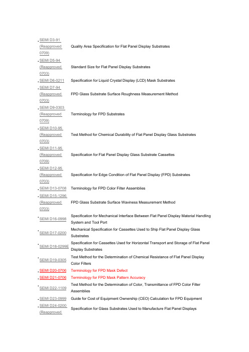
.SEMI D3-91(Reapproved0709)Quality Area Specification for Flat Panel Display Substrates.SEMI D5-94(Reapproved0703)Standard Size for Flat Panel Display Substrates.SEMI D6-0211Specification for Liquid Crystal Display (LCD) Mask Substrates.SEMI D7-94(Reapproved0703)FPD Glass Substrate Surface Roughness Measurement Method.SEMI D9-0303(Reapproved0709)Terminology for FPD Substrates.SEMI D10-95(Reapproved0703)Test Method for Chemical Durability of Flat Panel Display Glass Substrates .SEMI D11-95(Reapproved0709)Specification for Flat Panel Display Glass Substrate Cassettes.SEMI D12-95(Reapproved0703)Specification for Edge Condition of Flat Panel Display (FPD) Substrates.SEMI D13-0708Terminology for FPD Color Filter Assemblies.SEMI D15-1296(Reapproved0703)FPD Glass Substrate Surface Waviness Measurement Method.SEMI D16-0998Specification for Mechanical Interface Between Flat Panel Display Material Handling System and Tool Port.SEMI D17-0200Mechanical Specification for Cassettes Used to Ship Flat Panel Display Glass Substrates.SEMI D18-0299E Specification for Cassettes Used for Horizontal Transport and Storage of Flat Panel Display Substrates.SEMI D19-0305Test Method for the Determination of Chemical Resistance of Flat Panel Display Color Filters.SEMI D20-0706 Terminology for FPD Mask Defect.SEMI D21-0706 Terminology for FPD Mask Pattern Accuracy.SEMI D22-1109Test Method for the Determination of Color, Transmittance of FPD Color Filter Assemblies.SEMI D23-0999Guide for Cost of Equipment Ownership (CEO) Calculation for FPD Equipment .SEMI D24-0200(ReapprovedSpecification for Glass Substrates Used to Manufacture Flat Panel Displays0706).SEMI D25-0600E(Reapproved0706)Specification for Flat Panel Display Substrate Shipping Case.SEMI D26-1000 Provisional Specification for Large Area Masks for Flat Panel Displays (North America).SEMI D27-1000Guide for Flat Panel Display Equipment Communication Interfaces.SEMI D28-1101 (Reapproved 0708)Specification for Mechanical Interface Between Flat Panel Display Material Handling Equipment and Tool Port, Using Automated Guided Vehicle (AGV), Rail Guided Vehicle (RGV), and Manual Guided Vehicle (MGV).SEMI D29-1101(Reapproved0707)Test Method for Heat Resistance in Flat Panel Display (FPD) Color Filters .SEMI D30-0707Test Method for Light Resistance in Flat Panel Display (FPD) Color Filters.SEMI D31-1102Definition of Measurement Index (Semu) for Luminance Mura in FPD Image Quality Inspection.SEMI D32-0303 (Reapproved 0709)Specification for Improved Information Management for Glass FPD Substrates Through Orientation Corner Unification.SEMI D33-0703Measuring Method of Optical Characteristics for Backlight Unit .SEMI D34-0710Test Method for FPD Polarizing Films.SEMI D35-1103 (Reapproved 0709)Test Method for Measurement of Cold Cathode Fluorescent Lamp (CCFL) Characteristics.SEMI D36-0306Terminology for LCD Backlight Unit.SEMI D38-0211 Guide for Quality Area of LCD Masks.SEMI D39-0704(Reapproved0710)Specification for Markers on FPD Polarizing Films.SEMI D40-0704Terminology for FPD Substrate Deflection.SEMI D41-0305Measurement Method of SEMI MURA in FPD Image Quality Inspection.SEMI D42-0308 Specification for Ultra Large Size Mask Substrate Case.SEMI D43-1105Test Method for Mechanical Vibration in AMHS for FPD Manufacturing.SEMI D44-0706E S pecification for Reference Position of Single Substrate for Handing Off On Tool.SEMI D45-0706Measurement Methods for Resistance of Resin Black Matrix with High Resistance for FPD Color Filter.SEMI D46-0706Terminology for FPD Polarizing Films.SEMI D47-0307Test Method for Measurement of Bent Cold Cathode Flourescent Lamps.SEMI D48-1107Specification for Reference Position of Substrate ID to Specify Datum Line for ID Reader for Handing Off/On Tool.SEMI D49-0707Specification of Single Substrate Orientation for Loading/Unloading Into/From Equipment to Specify ID Reader Position.SEMI D50-0707Test Method for Surface Hardness of FPD Polarizing Film.SEMI D51-0709Specification for Handshake Method of Single Substrate for Handling Off/On Tool in FPD Production.SEMI D52-0708E S pecification for Reference Position of Substrate ID.SEMI D53-0708Specification for Liquid Crystal Display (LCD) Pellicles.SEMI D54-0709E S pecification for Substrate Management of FPD Production (SMS-FPD).SEMI D55-0310Guide for Evaluation Method of Color Performance for Color Filter Assemblies (Evaluation Method of Color Purity).SEMI D56-0310 Measurement Method for Ambient Contrast of Liquid Crystal Displays.SEMI D57-0310Definition of Measurement Index (VCT) for Mura in FPD Image Quality Inspection.SEMI D58-0310Terminology and Test Pattern for the Color Breakup of Field Sequential Color Display.SEMI D59-07103D Display Terminology.SEMI D60-0710Test Method of Surface Scratch Resistance for FPD Polarizing Film and Its Materials .SEMI D61-1110 Test Method of Perceptual Angle for OLED Displays.SEMI D62-0611Measurement Method of LED Light Bar for Liquid Crystal Displays.SEMI D63-0811Measurement Method for Depolarization Effect of FPD Color Filter.SEMI D64-0811Test Method for Measuring the Spatial Contrast Ratio of Flat Panel Display.SEMI D65-1011Measurement Method for the Color Breakup of Field Sequential Color Display.SEMI E82-1106Specification for Interbay/Intrabay AMHS SEM (IBSEM).SEMI E88-0307Specification for AMHS Storage SEM (Stocker SEM).SEMI E149-0708Guide for Equipment Supplier-Provided Documentation for the Acquisition and Use of Manufacturing Equipment.SEMI F49-0200(Reapproved1108)Guide for Semiconductor Factory Systems Voltage Sag Immunity.SEMI F50-0200(Reapproved1108)Guide for Electric Utility Voltage Sag Performance for Semiconductor Factories.SEMI F52-1101Dimensional Specification for Metric PFA Tubes for Semiconductor and Flat Panel Display Manufacturing.SEMI F65-1101Dimensional Specification for Mounting Bases of Diaphragm Valves Used with Metric PFA Tubes.SEMI F66-1101Specification for Port Marking and Symbol of Stainless Steel Vessels for Liquid Chemicals.SEMI F99-0705Dimensional Specification of a Diaphragm Valve for a Metric PFA Tube.SEMI F108-0310Guide for Integration of Liquid Chemical Piping Components for Semiconductor, Flat Panel Display, and Solar Cell Manufacturing Applications.SEMI S3-0306Safety Guideline for Process Liquid Heating Systems.SEMI S13-0305Environmental, Health and Safety Guideline for Documents Provided to the Equipment User for Use With Semiconductor Manufacturing Equipment.SEMI S17-0311Safety Guideline for Unmanned Transport Vehicle (UTV) Systems.SEMI S18-1102Environmental, Health, and Safety Guideline for Silane Family Gases Handling .SEMI S25-0706Safety Guideline for Hydrogen Peroxide Storage & Handling Systems.SEMI T8-1110Specification for Marking of Glass Flat Panel Display Substrates with a Two-dimensional Matrix Code Symbol.SEMI T17-0706Specification of Substrate Traceability.SEMI T18-1106Specification of Parts and Components Traceability。

概述美国国家半导体在销售的元件上进行标记,以便提供元件标识和制造的追溯性信息。
提供在元件上标记信息的方法取决于元件封装的大小和进行标记的可用区域,以及元件的性质和规格。
这里的信息描述了客户将观察到的大多数元件标记。
特定封装标记按每个元件的部件编号。
下面的链接讨论了常见的标记准则,以帮助了解与右侧示例中相类似的设备标记。
•特别代码•标准制造信息(第一行)•小组件制造信息(第一行)•典型元件描述(第二行)•其他的信息(第三行和第四行)•极小组件标记•军用/航空标记•强化塑料标记•其他标记•晶圆制造厂代码•装配厂代码•制造日期代码•裸片批次代码•元件系列,产品线和元件类型•电气等级信息•温度范围代码•封装代码•ROM 代码标记特别代码元件上的实际标记可能会与网上的定义有出入,以下的特别代码被解译成元件编号的真正代表字元。
美国国家半导体使用一些指定的字母来识别产品,例如“DD”Die Step Rev 会在元件标记中包含一个或两个“C”或“AA”,另一个例子“BBBBB”则是一个5位数字的裸片检阅号码,它可被解码成“43ABE”的真正字元。
•NS = 标准NS商标•U = 晶圆制造厂代码•Z = 装配厂代码•X = 1-日期或+ 号代表“ES”工程样本•XY = 两个位的日期代码•XYY = 三个位的日期代码•XXYY = 四个位的日期代码•TT = 两个位的裸片批次代码•E# = 含铅成份种类* (E0 - E7 per JESD97)•BBBBB= 五个位的裸片批次代码•DD = 一或两个位的Die Step Rev•SS = 晶圆筛选代码• C = 版权标记•M = 印在圈内的M•> = ESD标记•EP = 强化塑料识别• A = 检查批次号码•DIE-RUN-## = 10个位的晶圆批次/裸片批次号码•I = 微型SMD 引脚1指示•V = 微型SMD 一个位的裸片批次代码或“+”号表示為工程样品“ES”* - 假如空间容许标准制造信息(第一行)元件标记的第一行提供如下所示的制造信息。
Safety Guidelines 安全标准.SEMI AUX005-1101Comparison Matrix Between SEMI S2-93A and S2-0200 SEMI S2-93A and S2-0200判断矩阵.SEMI S1-0708E Safety Guideline for Equipment Safety Labels 设备安全标签安全标准.SEMI S2-0712d Environmental, Health, and Safety Guideline for Semiconductor Manufacturing Equipment 半导体制造设备环境、健康和安全标准.SEMI S3-1211Safety Guideline for Process Liquid Heating Systems 液体加热系统安全标准.SEMI S4-0304Safety Guideline for the Separation of Chemical Cylinders Contained in Dispensing Cabinets 化学品柜内化学品分离气缸的安全标准.SEMI S5-0310Safety Guideline for Sizing and Identifying Flow Limiting Devices for Gas Cylinder Valves 气缸阀门尺寸及流量限定装置的安全标准.SEMI S6-0707E EHS Guideline for Exhaust Ventilation of Semiconductor Manufacturing Equipment 半导体设备排风环境、健康和安全标准.SEMI S7-0310Safety Guideline for Evaluating Personnel and Evaluating Company Qualifications 评估人员及公司的资格安全标准.SEMI S8-0712a Safety Guidelines for Ergonomics Engineering of Semiconductor Manufacturing Equipment 半导体设备人体工学安全标准.SEMI S10-0215Safety Guideline for Risk Assessment and Risk Evaluation Process 风险评估安全标准.SEMI S12-0211Environmental, Health and Safety Guideline for Manufacturing Equipment Decontamination 设备去污环境、健康和安全标准.SEMI S13-0113Environmental, Health and Safety Guideline for Documents Provided to the Equipment User for Use With Manufacturing Equipment 提供给设备使用方的文件环境、健康和安全标准.SEMI S14-0309Safety Guidelines for Fire Risk Assessment and Mitigation for Semiconductor Manufacturing Equipment 半导体设备制造火灾风险评估及降低的安全标准.SEMI S16-0307 (Reapproved 0812)Guide for Semiconductor Manufacturing Equipment Design for Reduction of Environmental Impact at End of Life 半导体设备设计时降低设备生命周期到期对环境影响的标准.SEMI S17-0113Safety Guideline for Unmanned Transport Vehicle (UTV) Systems无人驾驶传送系统(UTV)的安全标准.SEMI S18-0312Environmental, Health, and Safety Guideline for Silane Flammable Silicon Compounds 硅烷易燃硅化合物的环境、健康和安全标准.SEMI S19-0311Safety Guideline for Training of Manufacturing Equipment Installation, Maintenance and Service Personnel 设备安装、维护和服务人员培训的安全标准.SEMI S21-1106E (Reapproved 0612)Safety Guideline for Worker Protection 工人保护安全标准.SEMI S22-0712a Safety Guideline for the Electrical Design of Semiconductor Manufacturing Equipment 半导体设备电气设计安全标准.SEMI S23-0813Guide for Conservation of Energy, Utilities and Materials Used by Semiconductor Manufacturing Equipment 半导体设备使用的能源、厂务和材料保护标准.SEMI S24-0306 (Reapproved 0811)Safety Guideline for Multi-Employer Work Areas 多雇主工作区域的安全标准.SEMI S25-0213Safety Guideline for Hydrogen Peroxide Storage & Handling Systems 过氧化氢的储存及处理系统的安全标准.SEMI S26-0811Environmental, Health, and Safety Guideline for FPD Manufacturing System FPD制造系统的环境、健康和安全标准.SEMI S27-0310Safety Guideline for the Contents of Environmental, Safety, and Health (ESH) Evaluation Reports 环境、健康和安全报告内容安全标准.SEMI S28-1011Safety Guideline for Robots and Load Ports Intended for Use in Semiconductor Manufacturing Equipment 半导体设备内机器人和负载端口的安全标准.SEMI S29-0712Guide for Fluorinated Greenhouse Gas (F-GHG) Emission Characterization and Reduction 氟化温室气体(F-GHG)降低和排放标准。
APPLICATIONS:FEATURES:•CCD Clock for VTR Camera •Equipment Connected to PCs •Low Profile Equipment•Lower Cost Crystal Oscillator Replacement •Computers and Peripherals•Portable Electronics (MP3 Players, Games)•Consumer Electronics such as TV’s, DVR’s, etc.•Vibrant, Shock-Prone & Humid Environments for Industrial Equipment •Demanding Military & Automotive ElectronicsLife Siz e5mmSTANDARD SPECIFICATIONS:ASFLM•Low Power Consumption •Low Stand by Current•Exceptional Stability Over Temp. at -40°C to +85°C •Available over Extended Temp Range •Low Cost-Compact QFN Plastic Packaging •Compact Package designAbsolute Maximum Ratings ParametersMinimumTypical Maximum Units Notes z H M 051 ----- 0.1:e g n a R y c n e u q e r F Operating Temperature: 0 ----- +70°C See optionsC °051+ -----55- :e r u t a r e p m e T e g a r o t Ss n o i t p o e e S 3.3+ ~ 8.1+:)d d V ( e g a t l o V y l p p u S Supply Current (no load):1.0 to 39.9999MHz----- 715 mA40.0 to 79.9999MHz ----- 8 15 80.0 to 124.9999MHz ----- 9 15 125.0 to 150MHz----- 10 15 Output Voltage: V OH 0.8*V dd ----- ----- V 15pF V OL ----- ----- 0.2*V ddRise Time: Fall Time:Tr ----- 1.33.0ns 15pF; T=25°C 20%/80%*VDD Tf-----1.33.0k 01 / x a m F p 51 :d a o L t u p t u O Ω min. pF See optionsd d V 2/1@ % 55 ----- 54 :y r te m m y S s m 0.3 5.1 ----- :e m i T p u t r a t S s n001 02 -----:e m i T e l b a s i D Disable Stand-by Current: ----- -----15 uA Tri-state Function (Stand-by) : "1" (VIH ≥0.75*Vdd) or Open: Oscillation"0" (VIH<0.25*Vdd) : Hi ZV z H M 001=F s p-----60 ----- :r e t t i j e l c y c o t e l c y Cr a e y t s r i Fm p p 0.5+ -----0.5-:g n i g A ItemMinimumMaximumUnitConditionSupply Voltage -0.3+4.0V Input Voltage -0.3Vdd+0.3 V Junction Temp. ----- +150°C Soldering Temp. -----+260°C 40sec maxESDHBM MM CDM2,000 200 500VNo load RL=∞ T=25°CVdd =3.3VProgrammed Orders (Quantity > 1,000pcs)Blank un-programmed oscillators are available for quick turn engineering requirements. Please call ABRACON for more information.Operating Temp. Freq. Stability EC: ± 50 ppm / -20°C to +70°C ER: ± 25 ppm / -20°C to +70°C LC: ± 50 ppm / -40°C to +85°C LR: ± 25 ppm / -40°C to +85°CPackaging Blank: 72pcs / Tube T: 1,000pcs / reel T3: 3,000pcs / reelTape and reel 1,000pcs/reelDimensions: mm(Left blank if standard)Note: Recommend using an approximately 0.01uF bypass capacitor between PIN 2 and 4.REFLOW PROFILE:Tube: 72 pcs/tubeUnit orientation in tube:AV LATTENTION: Abracon LLC’s products are COTS – Commercial-Off-The-Shelf products; suitable for Commercial, Industrial and, where designated, Automotive Applications.Abracon’s products are not specifically designed for Military, Aviation, Aerospace, Life-dependent Medical applications or any application requiring high reliability wherecomponent failure could result in loss of life and/or property. For applications requiring high reliability and/or presenting an extreme operating environment, written consent and Dimensions: mm (Inches)。
SEMI C3.55-0200 © SEMI 20001SEMI C3.55-0200STANDARD FOR SILANE (SiH 4), BULKThis standard was technically approved by the Global Gases Committee and is the direct responsibility of the North American Gases Committee. Current edition approved by the North American Regional Standards Committee on December 15, 1999. Initially available on SEMI OnLine January 2000; to be published February 2000.1 Description1.1 Silane is a pyrophoric, flamma ble colorless gas.2 Specifications QUALITY: 99.994%ImpuritiesMaximum AcceptableLevel (ppm)Gas PhaseCarbon Monoxide (CO)0.1Carbon Dioxide (CO 2)0.1Chlorosilanes (ionizable chlorides)including HCl, reported as chloride(Cl -)1Non-methane Hydrocarbons(C 2-C 4)0.1 total Hydrogen (H 2)50Methane (CH 4)0.1Nitrogen (N 2)1Argon (Ar)1Disiloxane (H 3SiOSiH 3)1Methyl Silane (SiH 3-CH 3)1Disilane (Si 2H 6)1Water (H 2O)(vol/vol)1Particles(See NOTE 1.)Total Specified Impurities57.4Deposited LayerCarbon (C)0.5 ppma (See NOTE 2.)Oxygen (O) 1 ppma (See NOTE 2.)Aluminum (Al)0.2 ppba (See NOTE 2.)Antimony (Sb)0.2 ppba (See NOTE 3.)Arsenic (As)0.2 ppba (See NOTE 3.)Boron (B)0.2 ppba (See NOTE 3.)Gallium (Ga)0.2 ppba (See NOTE 3.)Phosphorus (P)0.2 ppba (See NOTE 3.)Chromium (Cr)+ Copper (Cu)+Iron (Fe)+ Nickel (Ni)+ Zinc (Zn) 1.0 ppbatotal (See NOTE 3.)NOTE 1: To be determined between supplier and user.NOTE 2: ppma is defined to be atoms of impurity per 106 atoms of silicon.NOTE 3: ppba is defined to be atoms of impurity per 109 atoms of silicon.3 Electrical SpecificationResistivitygreater than 2,000 ohm-cm(n-type)4 Physical ConstantsMetric UnitsUS Units Molecular weight 32.11232.112Boiling point at 1 atm.-112°C -169°F Density of gas at 21.1°C (70°F) and 1 atm. 1.342 kg/m 30.0839 lb/ft 3Specific gravity of gas at 21.1°C and 1 atm (air = 1) 1.114 1.114Density of liquid at boilingpoint711 kg/m 344.39 lb/ft 35 Analytical Procedures (se e NOTE 1)5.1 Carbon Monoxide, Carbon Dioxide, Argon,Nitrogen and Methane — This procedure is for the determination of of carbon monoxide, carbon dioxide,argon, nitrogen and methane in silane using a gas chromatograph with a discharge ionization detector.5.1.1 Detection Limit — 30 ppb (mo le/mole)5.1.2 Instrument Parameters5.1.2.1 Column:HAYESEP D 60/80, 6.5 m (21.3 ft) by 3.2 mm (1/8 in)OD by 2.2 mm (0.085 in) ID stainless steel; or equivalent.5.1.2.2 Carrier Flow — 25 mL/min helium 5.1.2.3 Sample Volume — 1 mL 5.1.2.4 Temperatures:Detector 140°CColumn Oven40°C for 4 min., to 120°C at 10°C/min., hold 120°Cfor 8 min.Injection Temperature45°C5.1.3 Calibration Standards — 1 ppm (mole/mole) for all components to be tested, balance helium.SEMI C3.55-0200 © SEMI 200025.1.4 Operating Procedures5.1.4.1 Inject the calibration standard and sample as described in Section6.6 of SEMI C3. The order of elution is nitrogen, argon, carbon monoxide, methane,and carbon dioxide. (See NOTE 2.)5.1.4.2 Compare the average peak are a of the calibration standard to that of the silane sample being tested. Calculate the concentrations of the analytes as described in Section6.8 of SEMI C3. The result shall be reported in the unit of concentration needed and to the number of significant digits of the variable with the least number of significant digits. This value may not exceed that specified in Section 2.5.2 Total Chlorides — This procedure is for the determination of total chlorides in silane by titration of a hydrolyzed sample of silane. (See NOTE 1.)5.2.1 Detection Limit — 0.5 ppm (mole/mole)5.2.2 Instrument Parameters — See Figure 1.5.2.2.1 Equipment5.2.2.1.1 Safety purge regulator with proper fittings.5.2.2.1.2 Flow meter capable of measuring 0.25standard liters per minute (0.5 SCF/hour) (Brooks or equivalent), calibrated for silane.5.2.2.1.3 One cylinder of nitrogen with regulator.5.2.2.1.4 One ice bath.5.2.2.1.5 Three magnetic stirring bars.5.2.2.1.6 Two 2000 mL heavy-duty sidearm flasks (Fisher Cat. No. 10-181G or equivalent).5.2.2.1.7 One #9 one-hole rubber stopper.5.2.2.1.8 One #9 two-hole rubber stopper.5.2.2.1.9 Two Pyrex-brand tubes with fritted cylinders (Fisher Cat. No. 11-138B or equivalent).5.2.2.1.10 One gas washing bottle with fritted cylinder, 125 mL cap. (Fisher Cat. No. 03-040A or equivalent).5.2.2.1.11 One buret, 50 mL capacity with Teflon stopcock (Fisher Cat. No. 03-700-22C or equivalent).5.2.2.1.12 One buret stand (Fisher Cat. No. 14-688 or equivalent).5.2.2.1.13 Miscellaneous clamps, support stands, and rubber hose.5.2.2.1.14 Two 250 mL Erlenmeyer flasks.5.2.2.2 Reagents5.2.2.2.1 Potassium hydroxide flakes, technical (Fisher Cat. No. P-246 or equivalent).5.2.2.2.2 Mercuric nitrate crystal (Fisher Cat. No. M-168 or equivalent).5.2.2.2.3 Sodium chloride crystal (Fisher Cat. No. S-271 or equivalent).5.2.2.2.4 Diphenyl carbazone (Fisher Cat. No. D-86or equivalent).5.2.2.2.5 Bromophenol blue (Fisher Cat. No. B-392 or equivalent).5.2.2.2.6 Nitric acid (Fisher Cat. No. AA-200 or equivalent).5.2.2.2.7 Ethanol, denatured (Fisher Cat. No. AA-407or equivalent).5.2.3 Operating Procedure5.2.3.1 Assemble apparatus as shown in Figure 1 and purge entire system with nitrogen for 30 minutes.5.2.3.2 Fill each 2000 mL sidearm fla sk with about 1700 mL of 15% potassium hydroxide solution (15 g KOH per each 100 mL water).5.2.3.3 Fill the gas washing bottle with about 75 mL of deionized water that has been degassed.5.2.3.4 Pass exactly one cubic foot of silane through the system at a rate of 0.5 cubic feet per hour.5.2.3.5 Stop silane flow and purge system for 30minutes.5.2.3.6 Remove gas washing bottle fro m system and transfer contents quantitatively and with the aid of three 25 mL deionized water washings, to a 250 mL Erlenmeyer flask.5.2.3.7 Add a few drops of indicator solution, 5 g diphenyl carbazone plus 0.5 g bromophenol blue dissolved in 750 mL ethanol, plus 250 mL deionized water.5.2.3.8 Add, in a drop-wise fashion, sufficient 0.2 N HN03 (13 mL concentrated. HN03, diluted to 1 L in deionized water) in order to just turn the solution to yellow from purple.5.2.3.9 Titrate with a solution of merc uric nitrate Hg(NO 3)2, (diluted to 1000 mL in deionized water; then 50 mL diluted to 500 mL in deionized water) which has been previously standardized to 5.0 mL of a sodium chloride solution (approximately 165 ng NaCl,accurately weighed, dissolved in 100 mL deionized water).SEMI C3.55-0200 © SEMI 200035.2.4 Calibration5.2.4.1 Run titration blank consisting of 150 mL deionized water.5.2.4.2 Calculate the concentration of chloride, using the formula below. The result may not exceed the specification in Section 2 of this standard.wt.100mL −mL mL mL mL NaCl(g)100.0mL 60.66%Cl 100%NaCl 1L 0.005l 35.453g /mole 0.082atmL /moleK28.316L sample blank standard blank −××−××××1 × 10⁶ ppm = ppm Cl-5.3 Hydrocarbons C 2 – C 4 — This procedure is for thedetermination of hydrocarbons (methane, ethane, and propane) in silane using a gas chromatograph with a flame ionization detector.5.3.1 Detection Limit — 50 ppb (mole/mole)5.3.2 Instrument Parameters 5.3.2.1 Columns:Column 1:VZ-10, 60/80, 2 m (6.6 ft) by 3.2 mm (1/8in) OD by 2.2 mm (0.085 in) ID stainlesssteel;Column 2:VZ-10, 60/80, 1 m (3.3 ft) by 3.2 mm (1/8in) OD by 2.2 mm (0.085 in) ID stainlesssteel;or equivalent.5.3.2.2 Carrier Flow — 30 mL/min nitrogen 5.3.2.3 Sample Volume — 10 mL 5.3.2.4 Temperatures:Detector 150°C Column Oven45°C5.3.3 Calibration Standards — 1 ppm (mole/mole) for all components to be tested, balance helium.5.3.4 Operating Procedures — (see SEMI C3, Section 6, Gas Chromatography for standard procedures).5.3.4.1 Inject the calibration standard and sample as described in Section6.6 of SEMI C3. The order of elution is methane, ethane, propane and butane (see NOTE 2).5.3.4.2 Compare the average peak are a of the methane peak in the calibration standard to that of the hydrocarbons found in the silane sample being tested.Calculate the concentrations of the analytes as described in Section6.8 of SEMI C3 based on the methane response. The result shall be reported in the unit of concentration needed and to the number ofsignificant digits of the variable with the least number of significant digits. This value may not exceed that specified in Section 2.5.4 Hydrogen — This procedure is for the determination of hydrogen in silane using a gas chromatograph with a thermal conductivity detector.5.4.1 Detection Limit — 15 ppm (mole/mole)5.4.2 Instrument Parameters5.4.2.1 Columns:Molecular sieve 5A, 2.4 m (8 ft) by 6.4 mm (1/4 in) OD by 4.7 mm (0.185 in) ID, or equivalent.5.4.2.2 Carrier Flow — 30 mL/min ar gon 5.4.2.3 Sample Volume — 1.0 mL 5.4.2.4 Temperatures:Detector 40°C Column Oven40°C5.4.3 Calibration Standards — 20–100 ppm (mole/mole), balance argon.5.4.4 Operating Procedures — (see SEMI C3, Section 6, Gas Chromatography for standard procedures)5.4.4.1 Inject the calibration standard and sample as described in Section6.6 of SEMI C3. (See NOTE 2.)5.4.4.2 Compare the average peak are a of the hydrogen peak in the calibration standard to that of the hydrogen found in the silane sample being tested.Calculate the concentrations of the analytes as described in Section 6.8 of SEMI C3 based on the methane response. The result shall be reported in the unit of concentration needed and to the number of significant digits of the variable with the least number of significant digits. This value may not exceed that specified in Section 2.5.5 Disiloxane, Disilane and Methyl Silane — This procedure is for the determination of disiloxane,disilane and methyl silane in silane using a gas chromatograph with flame ionization detector.5.5.1 Detection Limit — 0.1 ppm (mole/mole)5.5.2 Instrument Parameters5.5.2.1 Column:28% DC-200 on Chromosorb PAW, 45/60 mesh, 14 m (46 ft) SS, or equivalent.5.5.2.2 Carrier Flow — 30 mL/min he lium 5.5.2.3 Sample Volume — 2 mL 5.5.2.4 Temperatures — Column 60°CSEMI C3.55-0200 © SEMI 200045.5.2.5 Calibration Standards — 1–5 ppm (mole/mole)5.5.3 Operating Procedure — (see SEMI C3, Section 6, Gas Chromatography for standard procedures).5.5.3.1 Inject the calibration standard and sample as described in Section6.6 of SEMI C3. The order of elution is silane matrix, methyl silane, siloxane (for information only) and disilane. (See NOTE 2.)5.5.3.2 Compare the average peak are a of the components being measured in the calibration standard to that of the same analytes found in the silane sample being tested. Calculate the concentrations of the analytes as described in Section 6.8 of SEMI C3. The result shall be reported in the unit of concentration needed and to the number of significant digits of the variable with the least number of significant digits.This value may not exceed that specified in Section 2.5.6 Water — This procedure is for the determination of trace moisture (water) in silane using a vibrating quartz hygrometer.5.6.1 Detection Limit — 0.1 ppm (vol/vol)5.6.2 Instrument Parameters5.6.2.1 Flow Requirements — Set the sample pressure and flow rate in accordance with the instrument manufacturer’s instructions.5.6.3 Calibration Standards — Che ck the hygrometer calibration with silane using an external permeation device. Construct a calibration curve which contains at least three points covering the range of interest. The standards employed will have been verified independently on a condensation dewpoint/frostpoint hygrometer. (See Figure 2.)5.6.4 Operating Procedure — At the first start-up of the hygrometer, calibrate it with moisture standards in silane. Then check the calibration once a month and modify the hygrometer if necessary. Direct standard to unit with stainless lines which have been purged. Note that silane is spontaneously flammable. Thus the experimental set-up should be leak-free and thoroughly purged before the introduction of silane. Obtain representative sample of the gas to be analyzed and direct to the unit. Wait until the equilibrium and read the moisture content. The result may not exceed the specification.5.6.4.1 Construct a calibration curve with previously verified standards. Direct standard to unit with stainless steel lines which have been purged.5.6.4.2 Obtain representative sample o f gas to be analyzed and direct to unit as with the standards. (See NOTE 1.)5.6.4.3 Construct a calibration curve a nd determine the ppm moisture content in sample gas. The result may not exceed the specification in Section 2 of this standard.5.7 Elemental Analysis in Deposited Layer —Procedures for the analysis of elemental impurities in deposited layers of polysilicon should be designated and should be referenced from a recognized industry standard (including but not limited to ISO, ASTM,etc.).5.7.1 Typical Detection LimitsCompound Detection Limit Carbon (C)0.2 ppma Oxygen (O)0.2 ppma Boron (B)0.02 ppba Aluminum (Al)0.02 ppba Gallium (Ga)0.02 ppba Phosphorus (P)0.02 ppba Arsenic (As)0.02 ppba Antimony (Sb)0.02 ppba Iron (Fe)0.3 ppba Chromium (Cr)0.01 ppba Nickel (Ni)0.2 ppba Copper (Cu)0.02 ppba Zinc (Zn)0.03 ppba5.8 Resistivity — Procedures for the measurement of resistivity in deposited layers of polysilicon should be designated and should be referenced from a recognized industry standard (including but not limited to ISO,ASTM, etc.).NOTE 1: Before performing this or any other analytical operation it is necessary to perform the following:• Familiarize yourself with the products involved and thepotential hazards by consulting the MSDS's for all hazardous substances involved and by consulting the CGA’s “Handbook of Compressed Gases” for all gases involved.• Know how to safely handle and store each hazardous gasby consulting the applicable CGA pamphlets.• Use all necessary and applicable personal protectiveequipment.• Follow all instructions relative to the safe operation ofthe equipment by consulting the LAC Safety Manual and applicable equipment manufacturers manual(s).It must be noted that silane is a pyrophoric gas and all sample plumbing must be purged of air completely before introducing silane. Extra special attention must be paid to leak checking all connections and checking the vent plumbing to be certain that effluents are vented properly. If there are anySEMI C3.55-0200 © SEMI 20005questionable connections or leaks, report this to the supervisor immediately and do not proceed with the analysis.NOTE 2: Introduce the calibration standard as many times as necessary to achieve the desired precision. Detection limitcalculated on these calibrations should achieve at least thatlisted for this procedure.Figure 1Chloride Scrubbing ApparatusFigure 2Moisture Analysis in SilaneSEMI C3.55-0200 © SEMI 20006NOTICE: These standards do not purport to address safety issues, if any, associated with their use. It is the responsibility of the user of these standards to establish appropriate safety and health practices and determine the applicability of regulatory limitations prior to use. SEMI makes no warranties or representations as to the suitability of the standards set forth herein for any particular application. The determination of the suitability of the standard is solely the responsibility of the user. Users are cautioned to refer to manufacturer's instructions, product labels,product data sheets, and other relevant literature respecting any materials mentioned herein. These standards are subject to change without notice.The user’s attention is called to the possibility that compliance with this standard may require use of copyrighted material or of an invention covered by patent rights. By publication of this standard, SEMI takes no position respecting the validity of any patent rights or copyrights asserted in connection with any item mentioned in this standard. Users of this standard are expressly advised that determination of any such patent rights or copyrights, and the risk of infringement of such rights, are entirely their own responsibility.Copyright by SEMI® (Semiconductor Equipment and Materials International), 805 East Middlefield Road, Mountain View, CA 94043.Reproduction of the contents in whole or in part is forbidden without express written consent of SEMI.。