研华工控机技术共25页文档
- 格式:ppt
- 大小:6.00 MB
- 文档页数:25
![工控机说明书ACP-4000 IPC-611 IPC-610_user_manual(CH)_ed[1].3_Final](https://uimg.taocdn.com/5724134de45c3b3567ec8b56.webp)
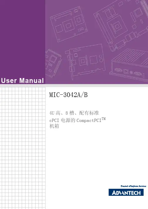
User ManualMIC-3042A/B4U高、8槽、配有标准cPCI电源的CompactPCI TM机箱版权声明随附本产品发行的文件为研华公司2008年版权所有,并保留相关权利。
针对本手册中相关产品的说明,研华公司保留随时变更的权利,恕不另行通知。
未经研华公司书面许可,本手册所有内容不得通过任何途径以任何形式复制、翻印、翻译或者传输。
本手册以提供正确、可靠的信息为出发点。
但是研华公司对于本手册的使用结果,或者因使用本手册而导致其它协力厂商的权益受损,概不负责。
认可声明PICMG TM、 CompactPCI TM和PICMG TM、CompactPCI TM标志是 PCI工业计算机制造厂商协会的注册商标。
所有其他产品名或商标均为各自所属方的财产。
CE本设备已通过CE 测试,符合以屏蔽电缆进行外部接线的环境规格标准。
建议用户使用屏蔽电缆,此种电缆可从研华公司购买。
如需订购,请与当地分销商联系。
产品质量保证(一年)从购买之日起,研华为原购买商提供一年的产品质量保证。
但对那些未经授权的维修人员维修过的产品并不进行质量保证。
研华对于不正确的使用、灾难、错误安装产生的问题有免责权利。
如果研华产品出现故障,在质保期内我们提供免费维修或更换服务。
对于出保产品,我们将会酌情收取材料费、人工服务费用。
请联系您的销售人员了解详细情况。
如果您认为您购买的产品出现了故障,请遵循以下步骤:1.收集您所遇到的问题的信息(例如,CPU主频、使用的研华产品及其它软件、硬件等)。
请注意屏幕上出现的任何不正常信息显示。
2.打电话给您的供货商,描述故障问题。
请借助手册,产品和任何有帮助的信息。
3.如果您的产品被诊断发生故障,请从您的供货商那里获得RMA(ReturnMaterial Authorization)序列号。
这可以让我们尽快的进行故障产品的回收。
4.请仔细的包装故障产品,并在包装中附上完整的售后服务卡片和购买日期证明(如销售发票)。
研华工控机基础教程(完整版)第一部分 引言工业控制计算机,中文简称工控机,英文简称IPC(Industry Personal Computer),在工业自动化背景下应运而生。
伴随着PC产业的发展,得到了长足的发展。
尽管IPC在架构上也是基于X86为主,在用户使用端和PC电脑产业相同,但与个人PC电脑产业的发展却完全是不同的道路。
个人PC通常分为家用电脑和商用电脑两大类。
对于家用电脑,是以时尚的外形、较高的显卡性能、多媒体显示性能、丰富的扩展性能、多声道声卡等方面作为吸引消费者的卖点,有些高档家用电脑甚至配备遥控器,时尚的音响,俨然一个家庭多媒体中心。
对于商用客户,则是通过稳重的外观、完备的售后服务、有限的扩展性能、高速度的运算速度等来吸引商用客户采购。
工控电脑是完全不同的设计理念,工控电脑更多的是在恶劣的环境下使用,对产品的易维护性、散热、防尘、产品周期、甚至尺寸方面都有着严格的要求。
因此在设计和选择工控机平台的时候,考虑的更多的是机构的设计,然后才是对性能等的考虑。
第二部分 正文一、工控机的设计分析与选择。
1、工控机的尺寸设计工控机在很多情况下使用是应用于某个系统之中,因此常常被放置在某个设备之中或上架。
因此对尺寸有较严格的要求。
根据用户的使用情况,分为上架式和壁挂式两种设计。
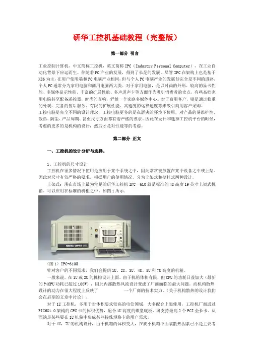
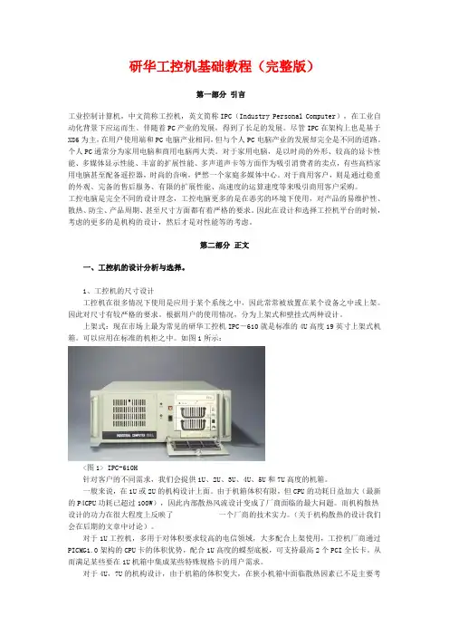
上架式:现在市场上最为常见的研华工控机IPC-610就是标准的4U高度19英寸上架式机箱。
可以应用在标准的机柜之中。
如图1所示:<图1> IPC-610H针对客户的不同需求,我们会提供1U、2U、3U、4U、5U和7U高度的机箱。
一般来说,在1U或2U的机构设计上面。
由于机箱体积有限,但CPU的功耗日益加大(最新的P4CPU功耗已超过100W),因此内部散热风流设计变成了厂商面临的最大问题。
而机构散热设计的功力在很大程度上反映了 一个厂商的技术实力。
(关于机构散热的设计我们会在后期的文章中讨论)。
对于1U工控机,多用于对体积要求较高的电信领域,大多配合上架使用,工控机厂商通过PICMG1.0架构的CPU卡的体积优势,配合1U高度的蝶型底板,可支持最高2个PCI全长卡。

ӧ ˉ ҮӐ ̖ Ӯ !智能自动化 无缝隙整合明星产品指南1明星产品指南TPC-31T/ 61T TPC-650H/1250H/1550H/1750H TPC-651H/1251H/1551HTPC-1840WP/2140WP SPC-1840WP/2140WP FPM-7181W/7211WWebOP-3070T WebOP-3100TWebOP-3150T 瘦客户端平板电脑18.5”/21.5”带有投射电容式触摸屏,Driect-VGA和DVI端口工业等级平板显示器• 18.5”WXGA高清TFT LCD宽屏显示• IP65防护等级全平面触摸屏• 超薄设计,前面板/壁挂式简易安装• 支持工业24VDC电源输入• 支持前面板,壁挂,台式和VESA手臂安装2工业平板电脑及人机界面智领工业平板电脑和人机界面新变革作为工业人机界面平台的领导厂商,研华为自动化领域细分市场提供先进的HMI产品解决方案,以满足不同领域对HMI产品独特的应用需求。
研华提供了全系列功能完备的人机界面产品,包括:工业级可编程人机界面(WebOP)、工业平板电脑(TPC&PPC)、产线自动化平板电脑(SPC)和工业显示器(FPM),同时,研华提供高价值标准化产品及解决方案和灵活的客制化产品,以满足工业应用的高质量需求,例如油气行业专用和阳光下可视化产品等。
此外,研华工业平板电脑及人机界面可通过集成I/O与带控制功能的HMI/SCADA软件,实现多种系统集成,开启自动化的新纪元。
18.5”WXGA/21.5”全高清TFT LCD,搭配AMD双核处理器多点触控工业等级平板电脑• AMD双核T56E,1.65GHz,支持外接APU,先进的图形处理性能 ,运行更高效• 16:9宽屏,带PCT多点触控• 内置智能键和功能键及定制化UI• 打开侧面板,轻松维护Cfast/HDD/Mini PCIe部件• 前面板LED指示灯显示操作状态7”WVGA Cortex™-A8 宽温可编程人机界面· Microsoft® Windows CE 6.0• 支持无电池状态下128KB(64字)FRAM储存备份• 电源&终端I/O串口隔离保护• -20~ 60ºC 宽操作温度• 前面板达IP66防护等级5.7”VGA/12.1”SVGA/15”XGA/17”SXGATFT LED LCD英特尔凌动瘦客户端• Intel®Atom™ N270 1.6GHz 处理器• 前面板IP65防护等级• 支持Microsoft® Windows XP/XPe/CE系统• 能源之星认证• 支持外接2.5”SATA HDD套件3.5”/5.7”QVGA TI AM3517 600MHz基于RISC触摸平板电脑• Microsoft®Windows CE 6.0• 1X SD卡槽,便于储存• 前面板达IP66防护等级• 超薄紧凑设计,搭配塑料外壳无风扇冷却系统• 自动数据流控制RS-4855.7”VGA/12.1”SVGA/15”XGA TFT LED LCD英特尔凌动瘦客户端,宽操作温度• Intel® Atom™ Z520 1.33 GHz处理器• -20~60ºC 宽操作温度• 串口隔离保护• 能源之星认证• 支持外接2.5”SATA HDD套件10.1” WSVGA Cortex™-A8 宽温可编程人机界面· Microsoft®Windows CE 6.0• 支持无电池状态下128KB(64字)FRAM储存备份• 电源&终端I/O串口隔离保护• -20~ 60ºC宽操作温度• 前面板达IP66防护等级15”XGA Cortex™-A8 宽温可编程人机界面· Microsoft® Windows CE 6.0• 支持无电池状态下128KB(64字)FRAM储存备份• 电源&终端I/O串口隔离保护• -20~ 60ºC宽操作温度• 前面板达IP66防护等级18.5”WXGA/21.5”全高清TFT LCD,搭配AMD双核处理器产线自动化多点触控工业等级平板电脑• AMD双核,1.65GHz,支持外接APU,先进的图形处理性能,运行更高效• 16:9宽屏,带PCT多点触控• 内置智能键和功能键及定制化UI• 抗划痕触摸表面:7级硬度• 带有IP65防护等级M12连接器• 前面板LED指示灯显示操作状态明星产品指南TPC-1071HPB/1271HPB/1571HPB/1771HPB TPC-1071HCA/1271HCA/1571HCA/1771HCA TPC-671H TPC-1571HTPC-1771H TPC-1071H/1271HWebOP-2040T WebOP-2100T WebOP-2080T 可编程人机界面控制平板电脑8”SVGA工业级可编程人机界面• 8”SVGA 65,536色真彩TFT LCD, 采用ARM9-based RISC高效能处理器• 前面板IP66防护等级• 10W低功耗设计• 支持300多种PLC工业通讯协议• 下载和保护灵活运行10.4”SVGA/ 12.1”SVGA/ 15”XGA/ 17”SXGA TFT LED LCD 英特尔凌动双核D525嵌入式平板电脑• Profibus总线支持• 兼容赫优讯 • 支持研华设计制造的profibus模块• 更完整可靠的验证平台及服务• 延续TPC-1071H/1271H/1571H/1771H 系列功能10.4”/12.1” SVGA TFT LCD 英特尔凌动双核D525嵌入式平板电脑• DDR3内存和多个I/O支持• PCIe及Mini PCIe扩展,便于工业无线现场总线控制• 内置数字量输入/输出模块• 串口及DI/DO隔离保护• 电池备份1MB SRAM 15”XGA TFT LCD 英特尔凌动双核D525嵌入式平板电脑• DDR3内存和多个I/O支持• PCIe及Mini PCIe扩展,便于工业无线现场总线控制• 内置数字量输入/输出模块• 串口及DI/DO隔离保护• 电池备份1MB SRAM 17”SXGA TFT LCD 英特尔凌动双核D525嵌入式平板电脑• DDR3内存和多个I/O支持• PCIe及Mini PCIe扩展,便于工业无线现场总线控制• 内置数字量输入/输出模块• 串口及DI/DO隔离保护• 电池备份1MB SRAM 10.4”SVGA/ 12.1”SVGA/ 15”XGA/ 17”SXGA TFT LED LCD英特尔双核D525嵌入式平板电脑• CIA认证CANopen模块和平台• 高速传输,速度最高可达1Mbps • 支持研华设计制造的profibus模块• 更完整可靠的验证平台及服务• 延续TPC-1071H/1271H/1571H/1771H 系列功能6.5”VGA LED LCD英特尔凌动Z510嵌入式平板电脑• Mini PCIe扩展,便于工业无线现场总线控制• 串口隔离保护• 自动数据流控制RS-485• 支持Microsoft ® WES7/XP/WES/WinCE系统• 10.1” WSVGA 65,536色真彩TFT LCD, 采用ARM9-based RISC高效能处理器• 前面板IP66防护等级• 10W低功耗设计• 支持300多种PLC工业通讯协议• 下载和保护灵活运行• 12.1” SVGA 65,536色真彩TFT LCD, 采用ARM9-based RISC高效能处理器• 前面板IP66防护等级• 10W低功耗设计• 支持300多种PLC工业通讯协议• 下载和保护灵活运行产品指南4.3”WQVGA工业级可编程人机界面• 4.3”WQVGA 65,536色真彩TFT LCD, 采用ARM9-based RISC高效能处理器• 前面板IP66防护等级• 10W低功耗设计• 支持300多种PLC工业通讯协议• 下载和保护灵活运行PPC-157/177PPC-6150/6170PPC-179IPPC-6192A/6172A/6152A IPPC-9151G/9171GIPPC-4001D/4008D FPM-5151G/5171G/5191G PPC-3100/3120FPM-3151G/3171G/3191G PPC-L62T FPM-2120G/2150G/2170G PPC-L158无风扇平板电脑多功能平板电脑工业平板电脑工业显示器10.4”/12”无风扇工业平板电脑,英特尔凌动D2550处理器 • TFT SVGA LED面板,搭配电阻触摸屏• 支持1个内部SATA 2.5存硬盘及1个mSATA接口• 可通过BIOS调节RS-232/422/485连接• COM1/COM2 pin9 RI/5V/12V可选择通过BIOS设定• 提供自动调校LED背光功能15”无风扇工业平板电脑,英特尔凌动D525处理器• 15”TFT XGA LCD 搭配可选的电阻式触摸屏• 支持1个内部的SATA 2 .5”硬盘,支持1个 Mini PCIe 插槽,双千兆以太网• 可选PCI/PCIe x1扩展组件• 1个RS -2 32/422/ 485端口;(支持自动数据流控制, BIOS可选)• 1个GPIO/RS-232 (8 通道, TTL 级); (通过排针交换),15”/ 17”无风扇工业平板电脑,英特尔酷睿双核处理器• Intel ® Core ™2 Duo 处理器,最高可达2.16 GHz • 系统内存高达4GB 667 MHz DDR2 SODIMM • 1个PCIe扩展插槽(PCI可选)• 1个RS -232/422/ 485端口;(支持自动数据流控制, BIOS可选)• 1个RS-232/GPIO (8通道, 提供TTL)(通过调换排针) 5.7”VGA TFT LCD 4U 19”/19” Half-size机架式工业等级平板电脑• 可固定的抽屉式超薄键盘&鼠标• 支持高性能Intel ® Core ™2双核处理器• 提供14/8扩展插槽,满足2 PICMG,10 PCI,2ISA/1 CPU PCI,3 PCI,4 SPCI • 带有防水功能薄膜的功能键(F1—F5),便于各种应用• 前端USB端口便于安插多种USB设备12”SVGA/15”XGA/17”SXGA工业显示器,带有抗反射触摸屏及Direct-VGA串口• 12”SVGA/15”XGA/17”SXGA TFT LCD LED 背光液晶显示• 铝制前面板,坚固设计• 前面板IP65防护等级• 带有RS-232 & USB接口15”XGA / 17” SXGA / 19” SXGA工业显示器,带抗反射触摸屏,Direct-VGA和DVI串口• 坚固不锈钢设计,铝合金前面板• 前面板OSD控制键• 支持工业24V DC 电源输入• 支持前面板,壁挂,台式,机架或VESA悬臂安装• 前面板IP65防护等级15” XGA / 17” SXGA / 19” SXGA多功能工业显示器,带抗反射触摸屏,Direct-VGA及DVI串口• Direct VGA & DVI-D视频输入接口• 可锁固OSD功能键,支持2组用户自定义对比度/亮度• 坚固不锈钢设计,铝合金前面板• 带有RS-232 & USB接口19”SXGA/17” SXGA/15” XGA TFT LCD 酷睿四核/酷睿双核处理器工业等级扩展型平板电脑• Intel ® Core ™ 2 Quad CPU (最高支持 2.8 GHz)/ Core ™ 2 Duo CPU (最高支持 3.0 GHz)• 双通道DDR3内存,容量高达4GB • 提供2个PCIe扩展槽• 双千兆以太网,Intel vPro技术• 提供2 x 2.5” SATA HDDs和RAID 0/1兼容15” XGA/17” SXGA 英特尔酷睿 i7/i5/i3赛扬处理器工业等级强固型平板电脑• 15” XGA /17” SXGA LED背光LCD,低功耗 , 前面 板提供USB接口, 支持1 x PCIe x 1或4(Gen2)• 带铝合金前面板的高强度不锈钢机箱,IP65防护等级, 确保设备的可靠运行• 支持双HDMI, LVDS, VGA显示; 1 x 2.5”SATA II或 III HDD和1 x CFast• 硬质阳极涂层以防止板磨损和酸腐蚀17”无风扇工业电脑英特尔双核处理器• Intel ® Core ™2 Duo LGA775 处理器, 最高可达3.0GHz • 支持240-pin DDR3 1333/1066 DIMM x 2, 最高可达4GB • 支持1个 Mini PCIe插槽,双千兆以太网• 提供1个PCI和1个PCIe扩展插槽• 1个RS -2 32/422/ 485端口;(支持自动数据流控制, BIOS可选)15”/17”无风扇平板电脑,英特尔酷睿i3 / i5 /赛扬处理器• Intel ® Core ™ i3,i5和 Celeron ® 847E + Intel QM77 PCH • 多种扩展插槽支持, PCIe x 4, 1 PCI + 1 PCIe x 1• 可选备份 HDD, 支持 Intel RAID • 1个独立的 RS-232/422/485 端口; (自动流控制,由 BIOS选择)• 1个GPIO/RS-232 (8 通道, TTL 级); (通过排针交换),双千兆以太网, 支持Intel AMT8.04 6.5”无风扇工业平板电脑,英特尔凌动处理器• 6.5” TFT VGA LCD,带LED背光灯• 系统内存高达2 GB DDR3• 铝质前面板设计• 支持双千兆以太网• 支持1个CFast 插槽• 可通过BIOS调节RS-232/422/485连接产品指南PCIE-1730PCIE-1752/1754/1756PCIE-1760USB-4702/4704USB-4711A/4716USB-4761PCI-1712PCI-1716PCI-1706/1714/1714L PCIE-1744PCI和PCIE数据采集&控制卡windows 7和windows 8操作系统,助力用户将研华的数据采集卡无缝地集成到最新平台,不仅提高了性能,也大大减少了开发时间。
研华工控机基础教程(完整版)第一部分引言工业控制计算机,中文简称工控机,英文简称IPC(Industry Personal Computer),在工业自动化背景下应运而生。
伴随着PC产业的发展,得到了长足的发展。
尽管IPC在架构上也是基于X86为主,在用户使用端和PC电脑产业相同,但与个人PC电脑产业的发展却完全是不同的道路。
个人PC通常分为家用电脑和商用电脑两大类。
对于家用电脑,是以时尚的外形、较高的显卡性能、多媒体显示性能、丰富的扩展性能、多声道声卡等方面作为吸引消费者的卖点,有些高档家用电脑甚至配备遥控器,时尚的音响,俨然一个家庭多媒体中心。
对于商用客户,则是通过稳重的外观、完备的售后服务、有限的扩展性能、高速度的运算速度等来吸引商用客户采购。
工控电脑是完全不同的设计理念,工控电脑更多的是在恶劣的环境下使用,对产品的易维护性、散热、防尘、产品周期、甚至尺寸方面都有着严格的要求。
因此在设计和选择工控机平台的时候,考虑的更多的是机构的设计,然后才是对性能等的考虑。
第二部分正文一、工控机的设计分析与选择。
1、工控机的尺寸设计工控机在很多情况下使用是应用于某个系统之中,因此常常被放置在某个设备之中或上架。
因此对尺寸有较严格的要求。
根据用户的使用情况,分为上架式和壁挂式两种设计。
上架式:现在市场上最为常见的研华工控机IPC-610就是标准的4U高度19英寸上架式机箱。
可以应用在标准的机柜之中。
如图1所示:<图1> IPC-610H针对客户的不同需求,我们会提供1U、2U、3U、4U、5U和7U高度的机箱。
一般来说,在1U或2U的机构设计上面。
由于机箱体积有限,但CPU的功耗日益加大(最新的P4CPU功耗已超过100W),因此内部散热风流设计变成了厂商面临的最大问题。
而机构散热设计的功力在很大程度上反映了一个厂商的技术实力。
(关于机构散热的设计我们会在后期的文章中讨论)。
对于1U工控机,多用于对体积要求较高的电信领域,大多配合上架使用,工控机厂商通过PICMG1.0架构的CPU卡的体积优势,配合1U高度的蝶型底板,可支持最高2个PCI全长卡。

Your ePlatform Partner基于PC的可编程控制器 ADAM-5510用户手册研华(中国)培训中心目录目录第一章 ADAM-5510介绍 (1)1.1概述 (1)1.2 ADAM-5510系统技术参数 (1)1.3 ADAM-5510/HC 系统功能及参数 (3)1.4系统配置 (3)第二章 ADAM-5510安装指南 (4)2.1 基本步骤 (4)2.2 I/O槽与I/O通道编号 (5)2.3 跳线设置和DIP开关设置 (5)2.4 安装 (7)2.5 布线与连接 (7)第三章ADAM-5000系列I/O 模块 (9)3.1 模拟量输入模块 (9)3.2 模拟量输出模块 (9)3.3 数字量输出/输入模块 (9)3.4 继电器输出模快 (9)3.5 计数器模块 (9)3.6 串口通讯模块 (9)3.7 I/O模块的设置 (10)第四章 ADAM-5510编程与下载 (11)4.1 编程 (11)4.2 ADAM-5510的下载与传输 (12)第五章 ADAM-5510 函数库 (14)5.1介绍 (14)5.2 ADAM-5510函数库 (14)第六章 TRACE MODE ADAM-5510快速入门 (16)6.1概述 (16)6.2 连接与下载运行 (16)6.3 创建工程 (19)6.4 自动建立和通信 (25)6.5 FBD程序开发 (29)6.6 开发人机界面 (33)6.7 通过GSM进行过程控制 (46)第七章 ADAM-5510与AUTOVIEW的连接 (56)7.1 软件组成 (56)7.2 头文件说明 (56)7.3 函数说明 (56)7.4.注意事项 (60)7.5 如何在A UTOVIEW中定义设备 (60)附 录 (61)基于PC的可编程控制器ADAM-5510 第一章 ADAM-5510介绍1.1概述ADAM-5510是基于 PC 的可独立完成数据采集与控制的可编程控制器。
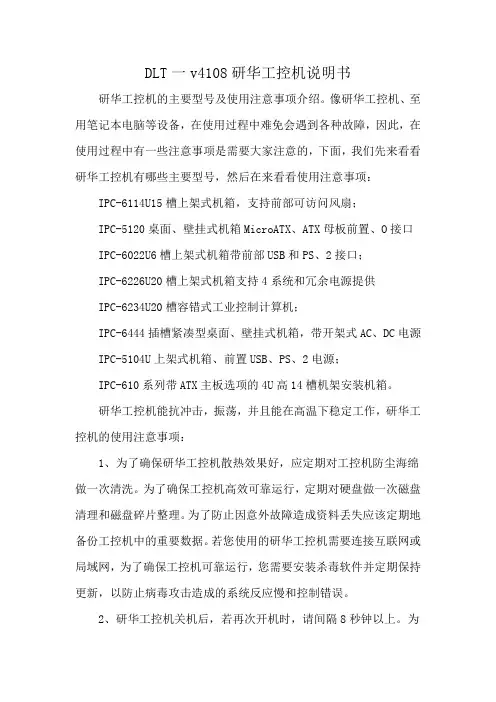
DLT一v4108研华工控机说明书研华工控机的主要型号及使用注意事项介绍。
像研华工控机、至用笔记本电脑等设备,在使用过程中难免会遇到各种故障,因此,在使用过程中有一些注意事项是需要大家注意的,下面,我们先来看看研华工控机有哪些主要型号,然后在来看看使用注意事项:IPC-6114U15槽上架式机箱,支持前部可访问风扇;IPC-5120桌面、壁挂式机箱MicroATX、ATX母板前置、O接口IPC-6022U6槽上架式机箱带前部USB和PS、2接口;IPC-6226U20槽上架式机箱支持4系统和冗余电源提供IPC-6234U20槽容错式工业控制计算机;IPC-6444插槽紧凑型桌面、壁挂式机箱,带开架式AC、DC电源IPC-5104U上架式机箱、前置USB、PS、2电源;IPC-610系列带ATX主板选项的4U高14槽机架安装机箱。
研华工控机能抗冲击,振荡,并且能在高温下稳定工作,研华工控机的使用注意事项:1、为了确保研华工控机散热效果好,应定期对工控机防尘海绵做一次清洗。
为了确保工控机高效可靠运行,定期对硬盘做一次磁盘清理和磁盘碎片整理。
为了防止因意外故障造成资料丢失应该定期地备份工控机中的重要数据。
若您使用的研华工控机需要连接互联网或局域网,为了确保工控机可靠运行,您需要安装杀毒软件并定期保持更新,以防止病毒攻击造成的系统反应慢和控制错误。
2、研华工控机关机后,若再次开机时,请间隔8秒钟以上。
为了确保工控机可靠运行,不要随意更改主板的BIOS设置。
不要带电插拔板卡,以免造成静电损坏。
当工控机遇到非人为原因停电时,为了确保工控机能正常可靠的工作,研维小编建议您立即将工控机电源断开,确认电网稳定后再通电运行,以保证工控机稳定运行。
3、必须使用正版许可的操作系统及相关应用软件。
若您要安装其它软件,请您确认该软件是否与研华工控机的操作系统兼容并请确认您的工控机硬件配置是否满足该软件对工控机硬件的要求。
4、在使用研华工控机过程中,请不要随意拆卸机器,若出现故障,请先参考工控机常见故障及排除办法。
User ManualAIMB-769AIMB-769 Socket LGA775 Intel®Core™ 2 Quad ATX with VGA, 2COM and Single LANAIMB-769 User Manual ii Safety InformationElectrical safety⏹To prevent electrical shock hazard, disconnect the power cable from the electri-cal outlet before relocating the system. ⏹When adding or removing devices to/from the system, ensure that the powercables for the devices are unplugged before the signal cables are connected. If possible, disconnect all power cables from the existing system before you add a device.⏹Before connecting or removing signal cables from the motherboard, ensure that all power cables are unplugged.⏹Seek professional assistance before using an adapter or extension cord. These devices could interrupt the grounding circuit.⏹Make sure that your power supply is set to the correct voltage in your area. If you are not sure about the voltage of the electrical outlet you are using, contact your local power company.⏹If the power supply is broken, do not try to fix it by yourself. Contact a qualified service technician or your retailer. Operation safety⏹Before installing the motherboard and adding devices on it, carefully read all the manuals that came with the package. ⏹Before using the product, make sure all cables are correctly connected and thepower cables are not damaged. If you detect any damage, contact your dealer immediately.⏹To avoid short circuits, keep paper clips, screws, and staples away from connec-tors, slots, sockets and circuitry.⏹Avoid dust, humidity, and temperature extremes. Do not place the product in any area where it may become wet.⏹Place the product on a stable surface.⏹If you encounter technical problems with the product, contact a qualified service technician or your retailer.Part No. 2006076900Edition 1Printed in TaiwanJuly 2011Caution!The symbol of the crossed out wheeled bin indicates that the product(electrical and electronic equipment) should not be placed in municipalwaste. Check local regulations for disposal of electronic products.A Message to the CustomerAdvantech Customer ServicesEach and every Advantech product is built to the most exacting specifications to ensure reliable performance in the harsh and demanding conditions typical of indus-trial environments. Whether your new Advantech equipment is destined for the labo-ratory or the factory floor, you can be assured that your product will provide the reliability and ease of operation for which the name Advantech has come to be known.Your satisfaction is our primary concern. Here is a guide to Advantech’s customer services. To ensure you get the full benefit of our services, please follow the instruc-tions below carefully.Technical SupportWe want you to get the maximum performance from your products. So if you run into technical difficulties, we are here to help. For the most frequently asked questions, you can easily find answers in your product documentation. These answers are nor-mally a lot more detailed than the ones we can give over the phone.So please consult this manual first. If you still cannot find the answer, gather all the information or questions that apply to your problem, and with the product close at hand, call your dealer. Our dealers are well trained and ready to give you the support you need to get the most from your Advantech products. In fact, most problems reported are minor and are able to be easily solved over the phone.In addition, free technical support is available from Advantech engineers every busi-ness day. We are always ready to give advice on application requirements or specific information on the installation and operation of any of our products.iii AIMB-769 User ManualAIMB-769 User Manual ivDeclaration of ConformityFCCThis device complies with the requirements in part 15 of the FCC rules:Operation is subject to the following two conditions:⏹This device may not cause harmful interference⏹This device must accept any interference received, including interference thatmay cause undesired operation.This equipment has been tested and found to comply with the limits for a Class A dig-ital device, pursuant to Part 15 of the FCC Rules. These limits are designed to pro-vide reasonable protection against harmful interference when the equipment is operated in a commercial environment. This equipment generates, uses, and can radiate radio frequency energy and, if not installed and used in accordance with the instruction manual, may cause harmful interference to radio communications. Opera-tion of this device in a residential area is likely to cause harmful interference in which case the user will be required to correct the interference at his/her own expense. The user is advised that any equipment changes or modifications not expressly approved by the party responsible for compliance would void the compliance to FCC regula-tions and therefore, the user's authority to operate the equipment.Caution!There is a danger of a new battery exploding if it is incorrectly installed.Do not attempt to recharge, force open, or heat the battery. Replace thebattery only with the same or equivalent type recommended by the man-ufacturer. Discard used batteries according to the manufacturer'sinstructions.CPU CompatibilityCPU Family sSpec.CoreSteppingPower Vcore FSBMfg.TechL2cacheAdvantechPNLong LifeSupportQuad Q9650 3.0 GHz EM64T Quad Core SLB8W E095 W0.8500V-1.3625V133345 nm12 MB NA NoCore Quad Q94002.66GHzEM64T Quad Core SLB6B R095 W0.85V-1.3625V133345 nm 6 MB96MP2QD-26FB-6M7TYesCore2 Quad Q93002.5GHz EM64T Quad Core SLAWE Ma98 W0.85V-1.3625V133345 nm 6 MB NA NoCore2 Quad Q82002.33 GHzEM64T Quad Core SLB5M M195 W0.85V-1.3625V133345 nm 4 MB NA NoCore2 Quad Q66002.4GHz EM64T Quad Core SL9UM B3105 W0.85V-1.5V106665 nm8 MB NA NoCore2 Quad Q66002.4GHz EM64T Quad Core SLACR B395 W0.85V-1.5V106665 nm8 MB96MP2QD-24FA-8M7TNoCore2 Duo E85003.16GHz EM63T Dual Core SLAPK C065 W0.85-1.3625V133345 nm 6 MB96MP2DD-31FB-6M7BNoCore2 Duo E84003.0GHz EM64T Dual Core SLB9J E065 W0.85V-1.3625V133345 nm 6 MB96MP2DD-3FB-6M7T1NoCore2 Duo E84003.0GHz EM64T Dual Core SLAPL C065 W0.85-1.3625V133345 nm 6 MB96MP2DD-3FB-6M7TYesCore2 Duo E82002.66GHz EM64T Dual Core SLAPP C065 W0.85-1.3625V133345 nm 6 MB NA NoCore2 DuoE75002.93GHz EM64T Dual Core SLGTE R065 W0.8500V-V1.3625106645 nm 3 MB96MP2DD-29FA-3M7T1NoCore2 Duo E74002.80GHz EM64T Dual Core SLB9Y R065 W0.85-1.3625V106645 nm 3 MB96MP2DD-28FA-3M7T1/SLGW3YesCore2 Duo E73002.66GHz EM64T Dual Core SLAPB M065 W0.85-1.3625V106645 nm 3 MB NA NoCore2 Duo E72002.53GHz EM64T Dual Core SLAVN M065 W0.85-1.3625V106645 nm 3 MB NA NoCore2 Duo E67502.66GHz EM64T Dual Core SLA9V G065W0.85-1.5V133365 nm 4 MB96MP2DD-26FB-4M7TNoCore2 Duo E67002.66GHz EM64T Dual Core SL9S7B265 W0.850-1.3525V106665 nm 4 MB96MP2DD-26FA-4M7TYesCore2 Duo E66002.40GHz EM64T Dual Core SL9S8B265 W0.850-1.3525V106665 nm 4 MB96MP2DD-24FA-4M7TNoCore2 Duo E65502.33GHz EM64T Dual Core SLA9X G065 W0.962V-1.350V133365 nm 4 MB NA NoCore2 Duo E65002.93GHz EM64T Dual Core SLGUH R065 W0.962V-1.350V106645 nm 2 MB96MPPD-2.93-2M7TYesCore2 Duo E64002.13GHz EM64T Dual Core SL9S9B265 W0.850-1.3525V106665 nm 2 MB96MP2DD-21FA-2M7TNov AIMB-769 User ManualCore2 Duo E63001.86GHz EM64T Dual Core SL9SA B265 W0.850-1.3525V106665 nm 2 MB96MP2DD-18FA-2M7TNoCore2 Duo E64202.13GHz EM64T Dual Core SLA4T B265 W0.850-1.5V106665 nm 4 MB NA NoCore2 Duo E63201.86GHz EM64T Dual Core SLA4U B265 W0.850-1.5V106665 nm 4 MB NA NoCore2 Duo E53002.6GHz EM64T Dual Core SLB9U R065 W0.85V-1.3625V80045 nm 2 MB NA YesCore2 Duo E47002.6GHz EM64T Dual Core SLALT G065 W1.162V-1.312V80065 nm 2 MB NA NoCore2 Duo E45002.2GHz EM64T Dual Core SLA95M065 W0.850-1 5V80065 nm 2 MB NA NoCore2 Duo E44002.0GHz EM64T Dual Core SLA3F L265 W1.162V-1.312V80065 nm 2 MB NA NoCore2 Duo E43001.8GHz EM64T Dual Core SL9TB L265 W0.85V-1.5V80065 nm 2 MB96MP2DD-18F8-2M7TYesPentium Dual-Core 1.8GHz E2160SLA8Z M065 W0.85V-1.5V80065 nm 1 MB96MPPD-1.8F8-1M7TYesPentium Dual-Core 1.6GHz E2140SLA3J L265 W1.162V-1.312V80065 nm 1 MB NA NoCeleron E1200 1.6GHz EM64T SLAQW M065 W1.162V-1.312V80065 nm512KB96MPC2-1.6F8-5K7TNoCeleron 440 2GHz SL9XL A135 W 1.0-1.3375V80065 nm512KB96MPC4-2.0F8-5K7TYesCeleron 430 1.8GHz SL9XN A135 W 1.0-1 3375V80065 nm512KB96MPC4-1.8F8-5K7TNoCeleron 420 1.6GHz SL9XP A135 W 1.0-1 3375V80065 nm512KBNA NoAIMB-769 User Manual viMemory CompatibilityBrand Size Speed Type ECC Vendor PN Advantech PN MemoryTranscend 1 GBDDR31066DDR3NTS128MLK64V1U/TS2KNU28100-1S96D3-1G1066NN-TRSECK4B1G0846D-HCF8 (128x8)1 GBDDR31066DDR3N TS128MLK64V1U96D3-1G1066NN-TRSECK4B1G0846DHCH9 ENJ038A3(128x8)2 GBDDR31066DDR3NTS256MLK64V1U/TS5KNU28300-1S96D3-2G1066NN-TRSECK4B1G0846D-HCF9(128x8)Apacer 1 GBDDR31066DDR3N78.01GC3.42096D3-1G1066NN-APELPIDAJ1108BDBG-DJ-F (128x8)2 GBDDR31066DDR3N78.A1GC3.42196D3-2G1066NN-APELPIDAJ1108BDBG-DJ-F (128x8)DSL 1 GBDDR31066DDR3N D3UE28081XH18AB NAELPIDAJ1108BDSE-DJ-F(128x8)2 GBDDR31066DDR3N D3UE28082XH18AB NAELPIDAJ1108BDSE-DJ-F(128x8)Transcend 1 GBDDR31333DDR3N TS128MLK64V3U96D3-1G-1333NN-TRELPIDAJ1108BDBG-DJ-F(128x8)1 GBDDR31333DDR3N TS128MLK64V3U NAMicron 9GF22D9KPT (128x8) 2 GBDDR31333DDR3N TS256MLK64V3U NASEC 907 HCH9K4B1G08460(128x8)Apacer 1 GBDDR31333DDR3N78.01GC6.42096D3-1G1333NN-APELPIDAJ1108BFBG-DJ-F(128x8)2 GBDDR31333DDR3N78.A1GC6.42196D3-2G1333NN-APELPIDAJ1108BDBG-DJ-F (128x8)DSL 1 GBDDR31333DDR3N D3UE28081XH18AB NAELPIDAJ1108BDSE-DJ-F(128x8)2 GBDDR31333DDR3N D3UE28082XH18AB NAELPIDAJ1108BDSE-DJ-F(128x8)Kingston 1 GBDDR31333DDR3N KVR1333D3N9/1G NAHYNIXH5TQ1G83BFRH9C 928AK(128x8)2 GBDDR31333DDR3N TS128MLK64V3U NAELPIDAJ1108BDBG-DJ-F 093309DLK20(256x8)ATP 4 GB DDR31333DDR3N AQ12M64B8BKH9S NASAMSUNG 949K4B2G0846B-HCH9 (256x8)vii AIMB-769 User ManualOrdering InformationAIMB-769 Ordering InformationPart Number Chipset Display GbE PCIe x 16PCIe x 1PCIAIMB-769VG-00A1E G41/ICH7VGA1115Product Warranty (2 years)Advantech warrants to you, the original purchaser, that each of its products will be free from defects in materials and workmanship for two years from the date of pur-chase.This warranty does not apply to any products which have been repaired or altered by persons other than repair personnel authorized by Advantech, or which have been subject to misuse, abuse, accident or improper installation. Advantech assumes no liability under the terms of this warranty as a consequence of such events.Because of Advantech’s high quality-control standards and rigorous testing, most of our customers never need to use our repair service. If an Advantech product is defec-tive, it will be repaired or replaced at no charge during the warranty period. For out-of-warranty repairs, you will be billed according to the cost of replacement materials, service time and freight. Please consult your dealer for more details.If you think you have a defective product, follow these steps:1.Collect all the information about the problem encountered. (For example, CPUspeed, Advantech products used, other hardware and software used, etc.) Noteanything abnormal and list any onscreen messages you get when the problemoccurs.2.Call your dealer and describe the problem. Please have your manual, product,and any helpful information readily available.3.If your product is diagnosed as defective, obtain an RMA (return merchandiseauthorization) number from your dealer. This allows us to process your returnmore quickly.4.Carefully pack the defective product, a fully-completed Repair and ReplacementOrder Card and a photocopy proof of purchase date (such as your sales receipt)in a shippable container. A product returned without proof of the purchase dateis not eligible for warranty service.5.Write the RMA number visibly on the outside of the package and ship it prepaidto your dealer.AIMB-769 User Manual viiiInitial InspectionBefore you begin installing your motherboard, please make sure that the following materials have been shipped:⏹AIMB-769 Socket LGA 775 Intel® Core TM 2 Quad / Core TM 2 Duo / Intel® Pen-tium TM / Celeron TM FSB 1333 MHz Processor-based ATX Motherboard withVGA, 2 COM and single LAN⏹ 1 x AIMB-769 startup manual⏹ 1 x CD with driver, utility and user manual⏹ 2 x Serial ATA HDD data cable⏹ 2 x Serial ATA HDD power cable⏹ 1 x I/O port bracket⏹ 1 x jumper package⏹ 1 x warranty cardIf any of these items are missing or damaged, contact your distributor or sales repre-sentative immediately. We have carefully inspected the AIMB-769 mechanically and electrically before shipment. It should be free of marks and scratches and in perfect working order upon receipt. As you unpack the AIMB-769, check it for signs of ship-ping damage. (For example, damaged box, scratches, dents, etc.) If it is damaged or it fails to meet the specifications, notify our service department or your local sales representative immediately. Also notify the carrier. Retain the shipping carton and packing material for inspection by the carrier. After inspection, we will make arrange-ments to repair or replace the unit.ix AIMB-769 User ManualAIMB-769 User Manual xContentsChapter1General Information (1)1.1Introduction (2)1.2Features (2)1.3Specifications (2)1.3.1System (2)1.3.2Memory (2)1.3.3Input/Output (2)1.3.4Graphics (3)1.3.5Ethernet LAN (3)1.3.6Industrial features (3)1.3.7Mechanical and environmental specifications (3)1.4Jumpers and Connectors (3)Table 1.1:Jumpers (3)Table 1.2:Connectors (4)1.5Board layout: Jumper and Connector Locations (5)Figure 1.1Jumper and Connector Location (5)Figure 1.2I/O Connectors (5)1.6AIMB-769 Block Diagram (6)Figure 1.3AIMB-769 Block Diagram (6)1.7Safety Precautions (7)1.8Jumper Settings (8)1.8.1How to set jumpers (8)1.8.2CMOS clear (CMOS1) (8)Table 1.3:CMOS1 (8)1.8.3Chassis intruction connector (JCASE1) (8)1.8.4ATX/AT mode selector (PSON1) (8)Table 1.4:ATX/AT mode selector (PSON1) (8)1.9System Memory (9)1.10Memory Installation Procedures (9)1.11Cache Memory (9)1.12Processor Installation (9)Chapter2Connecting Peripherals (11)2.1Introduction (12)2.2USB and LAN Ports (USB12/LAN1_USB34) (12)Table 2.1:LAN LED Indicator (12)2.3VGA Connector (VGA1) (13)2.4Serial Ports (COM1 ~ COM2) (13)2.5PS/2 Keyboard and Mouse Connector (KBMS1) (14)2.6CPU Fan Connector (CPUFAN1) (15)2.7System FAN Connector (SYSFAN1/2) (15)2.8Front Panel Connectors (JFP1/2/3) (16)2.8.1ATX Soft Power Switch (JFP1) (16)2.8.2Reset Connector (JFP1) (16)2.8.3External Speaker (JFP2) (17)2.8.4HDD LED Connector (JFP2) (17)2.8.5SMBus Connector (JFP2) (17)2.8.6Power LED and keyboard lock connector (JFP3/PWR_LED&KEYLOCK) (18)Table 2.2:ATX power supply LED status (No support for AT pow-er) (18)2.9Line Out and Mic In Connector (AUDIO1) (19)2.10Serial ATA Interface (SATA 1/2/3/4) (19)xi AIMB-769 User Manual2.11ATX Power Connector (ATX12V1, EATXPWR1) (20)2.12Front Panel Audio Connector (FPAUD1) (21)2.13USB 2.0 Connector (USB 56, 78) (21)2.14Digital Audio Connector(SPDIF_OUT1) (22)2.15Connector to alarm board for monitoring (VOLT1) (23)2.16Serial Port DC Power Switch (CN32, CN33) (24)Chapter3BIOS Operation (25)3.1Introduction (26)3.2BIOS Setup (26)3.2.1Main Menu (27)3.2.2Advanced BIOS Features (28)3.2.3Advanced PCI/PnP Setting (36)3.2.4Boot Setting (37)3.2.5Boot Device Priority (38)3.2.6Hard Disk Drives (38)3.2.7Removable Drivers (38)3.2.8Security Setting (38)3.2.9Advanced Chipset Settings (39)3.2.10Exit Option (42)Chapter4Chipset Software Installation Utility434.1Before you begin (44)4.2Introduction (44)4.3Windows XP/Windows 7 Driver Setup (45)Chapter5VGA Setup (47)5.1Introduction (48)5.2Windows XP/7 (48)Chapter6LAN Configuration (49)6.1Introduction (50)6.2Features (50)6.3Installation (50)6.4Windows XP/ Windows 7 Setup (REALTEK RTL8111DL) (50)Appendix A Programming the Watchdog Timer.51A.1Programming the Watchdog Timer (52)A.1.1Watchdog timer overview (52)A.1.2Programming the Watchdog Timer (52)Table A.1:Watchdog Timer Registers (54)A.1.3Example Program (55)Appendix B I/O Pin Assignments (59)B.1USB Header (USB56) (60)Table B.1:USB Header (USB56) (60)B.2USB Header (USB78) (60)Table B.2:USB Header (USB78) (60)B.3VGA Connector (VGA1) (61)AIMB-769 User Manual xiiTable B.3:VGA Connector (VGA1) (61)B.4PS/2 Keyboard and Mouse Connector (KBMS1) (61)Table B.4:PS/2 Keyboard and Mouse Connector (KBMS1) (61)B.5CPU Fan Power Connector (CPUFAN1) (62)Table B.5:CPU Fan Power Connector (CPUFAN1) (62)B.6System Fan Power Connector (SYSFAN1/SYSFAN2) (62)Table B.6:System Fan Power Connector (SYSFAN1/SYSFAN2) (62)B.7Front Panel Connectors (JFP1/2) (63)B.7.1Power LED & Keyboard Lock Connector (JFP3) (63)Table B.7:Power LED & Keyboard Lock Connector (JFP3) (63)B.7.2Power switch/HDD LED/SMBus/Speaker (JFP1/JFP2) (63)Table B.8:Power Switch/HDD LED/SMBus/Speaker (JFP1/JFP2) (64)B.8ATX1 12 V Auxiliary Power Connector (ATX12V) (64)Table B.9:ATX1 12 V Auxiliary Power Connector (ATX12V1)..64 B.9ATX Power Connector (EATXPWR1) (64)Table B.10:ATX Power Connector (ATX2) (64)B.10USB/LAN ports (LAN1_USB34) (65)Table B.11:USB Port (65)Table B.12:Ethernet 10/100/1000 Base-T RJ-45 Port (65)B.11Line Out, Mic In Connector (AUDIO1) (65)B.12Serial ATA1 (SATA1) (65)Table B.13:Serial ATA0 (SATA1) (65)B.13Serial ATA2 (SATA2) (66)Table B.14:Serial ATA1 (SATA2) (66)B.14Serial ATA3 (SATA3) (66)Table B.15:Serial ATA2 (SATA3) (66)B.15Serial ATA4 (SATA4) (66)Table B.16:Serial ATA3 (SATA4) (66)B.16AT/ATX Mode (PSON1) (66)Table B.17:AT/ATX Mode (PSON1) (66)B.17FPAUD1(Front Panel Audio Connector) (67)Table B.18:Front Panel Audio Connector (FPAUD1) (67)B.18System I/O Ports (67)Table B.19:System I/O Ports (67)B.19JCASE1(Open Case Connector) (68)Table B.20:Case Open Connector(JCASE1) (68)B.20DMA Channel Assignments (68)Table B.21:DMA Channel Assignments (68)B.21Interrupt Assignments (68)Table B.22:Interrupt Assignments (68)B.221st MB Memory Map (69)Table B.23:1st MB Memory Map (69)xiii AIMB-769 User ManualAIMB-769 User Manual xivChapter11.1IntroductionAIMB-769 is designed with Intel® G41 and ICH7 Express chipsets for industrial appli-cations that need high computing and rich strong I/O capability. It supports 45nm and 65nm Intel® Core 2 Duo, Core 2 Quad, Pentium Dual-Core and Celeron 400 series processors with FSB up to 1333 MHz and DDR3 800/1066 MHz SDRAM up to 4 GB.AIMB-769 also features excellent graphic processing capability from its embedded Intel® Graphics Media Accelerator X4500 with shared memory up to 352 MB—pro-viding strong 2D/3D graphic processing power that saves on extra cost, power con-sumption and thermal design effort caused by an add-on graphic card.1.2Features⏹G41 chipset: Supports 800/1066/1333MHz front side bus⏹I/O connectivity: AIMB-769 supports 1 PCIe x16 slot, 1 PCIe x1 slot, and 5PCI. It also supports single Gigabit LAN via PCIe x1 bus, 4 SATAII connectorsand 8 USB 2.0 ports⏹COM port with DC power support: AIMB-769 supports two RS-232 with DCpower (+5 V or +12 V) support which is useful for some industrial applicationsfor simplifying cable deployment⏹Standard ATX form factor with industrial features: AIMB-769 provides indus-trial features like long-life product support, reliable operation under wide temper-ature ranges, watchdog timer, CMOS backup functions and more.⏹BIOS CMOS backup and restore: When BIOS CMOS setup has been com-pleted, data in the CMOS RAM is automatically backed up to the Flash ROM.This is particularly useful in harsh environments which may cause setup dataloss such as battery failure. Upon such an error occurring, the BIOS will checkthe data, and automatically restore the original data for booting⏹Optimized integrated graphic solution: Intel® Graphics Media AcceleratorX4500 with strong 2D/3D graphic processing power.1.3Specifications1.3.1System⏹CPU: LGA 775 Intel Core 2 Quad up to 3.0 GHz/Core 2 Duo up to 3.16 GHz/Pentium Dual-Core up to 2.93 GHz/Celeron up to 2.2 GHz with 800/1066/1333MHz front side bus⏹BIOS: AMI SPI 16-Mbit BIOS⏹System chipset: Intel G41 with ICH7⏹SATA II hard disk drive interface: Four on-board SATA II connectors with datatransmission rate up to 300 MB/s1.3.2Memory⏹RAM: Up to 4 GB in 2 slots 240-pin DIMM sockets. Supports dual channelDDR3 800/1066 MHz SDRAM1.3.3Input/Output⏹PCIe bus: 1 PCIe x16 slot and 1 PCIe x1 slot⏹PCI Bus: 5 PCI slots, 32-bit, 33 MHz PCI 2.2 compliant⏹Floppy disk drive interface: Supports one floppy disk drive, 5 1/4" (360 KBand 1.2 MB) or 3 1/2" (720 KB, 1.44 MB). BIOS can enable/disable this function. AIMB-769 User Manual23AIMB-769 User Manual Chapter 1General Information⏹Serial ports: Two RS-232 serial ports with DC power(+5 V or +12 V) support for industrial applications ⏹Keyboard/mouse connector: Supports standard PS/2 keyboard and mouse ⏹USB port: Supports up to eight USB 2.0 ports with transmission rates up to 480Mbps. Four ports are on-board pin heaters and four ports are external ports 1.3.4Graphics⏹Controller: Chipset integrated VGA controller ⏹Display memory: Dynamically shared system memory up to 352 MB ⏹CRT: Up to 2048 x 1536 resolution @ 75 Hz refresh rate 1.3.5Ethernet LAN⏹Supporting single 10/100/1000Base-T Ethernet port via PCIe x1 bus ⏹Controller: REALTEK RTL8111DL1.3.6Industrial features⏹Watchdog timer: This function can reset system when it is triggered. Thewatchdog timer is programmable, with units in minutes and seconds (255 lev-els).1.3.7Mechanical and environmental specifications⏹Operating temperature: 0 ~ 60° C (32 ~ 140° F, depending on CPU)⏹Storage temperature: -40 ~ 85° C (-40 ~ 185° F)⏹Humidity: 5 ~ 95% non-condensing⏹Power supply voltage: +3.3 V, +5 V, +12 V, -12 V, 5 V SB⏹Power consumption: Maximum: +5 V at 1.76 A, +3.3 V at 2.28 A, +12 V at 4.7A, 5 VSB at 0.19 A, (Intel Core 2 Quad Q9650 3.0 GHz (1333 MHz FSB), 2 x 1GB DDR3 1066 SDRAM)⏹Board size: 304.8 x 228.6 mm (12" x 9.6")⏹Board weight: 0.5 kg (1.68 lb)1.4Jumpers and ConnectorsConnectors on the AIMB-769 motherboard link it to external devices such as hard disk drives and keyboard. In addition, the board has a number of jumpers used to configure the system for your application.The tables below list the function of each of the board jumpers and connectors. Later sections in this chapter give instructions on setting jumpers. Chapter 2 gives instruc-tions for connecting external devices to your bel Function CMOS1Clear CMOS JCASE1 Chassis instruction connectorPSON1AT/ATX mode selectorJOBS1OBS Alarm switchJWDT1Watchdog timer output optionLabel FunctionJFP1Power Switch / Reset connectorJFP2External speaker / HDD LED connector / SMBus connectorJFP3Keyboard Lock and Power LED Suspend: Fast flash (ATX) System On: ON (ATX/AT) System Off: OFF (AT)System Off: Slow flash (ATX)USB56USB port 5, 6USB78USB port 7, 8VGA1VGA connectorVOLT1Voltage monitoring for alarm boardCOM 1,2Serial port: RS-232KBMS1PS/2 keyboard and Mouse connectorKBMS2PS/2 keyboard and Mouse connector (on board)CPUFAN1CPU FAN connectorSYSFAN1System FAN connector 1SYSFAN2System FAN connector 2USB12USB port 1, 2LAN1_USB34LAN1/USB port 3, 4SATA 1 ~ 4Serial ATA connectorATX12V1ATX 12V Auxiliary power connectorEATXPWR1ATX power connectorAUDIO1Audio connectorFPAUD1Front Panel audio connectorSPDIF_OUT1Digital Audio connectorFDD1 FDD connectorCN32COM1 Power SwitchCN33COM2 Power SwitchIR_CON InfraredconnectorAIMB-769 User Manual45AIMB-769 User Manual Chapter 1General Information1.5Board layout: Jumper and Connector Locations Figure 1.1 Jumper and Connector Location Figure 1.2 I/O Connectors SYSFAN2CPUFAN1SYSFAN11.6AIMB-769 Block DiagramFigure 1.3 AIMB-769 Block Diagram AIMB-769 User Manual67AIMB-769 User Manual Chapter 1General Information1.7Safety PrecautionsWarning!Always completely disconnect the power cord from your chassis when-ever you work with the hardware. Do not make connections while thepower is on. Sensitive electronic components can be damaged by sud-den power surges. Only experienced electronics personnel should openthe PC chassis.Caution!Always ground yourself to remove any static charge before touching themotherboard. Modern electronic devices are very sensitive to electro-static discharges. As a safety precaution, use a grounding wrist strap atall times. Place all electronic components on a static-dissipative surfaceor in a static-shielded bag when they are not in the chassis.Caution!The computer is provided with a battery-powered real-time clock circuit.There is a danger of explosion if battery is incorrectly replaced. Replaceonly with same or equivalent type recommended by the manufacturer.Discard used batteries according to manufacturer's instructions.Caution!There is a danger of a new battery exploding if it is incorrectly installed.Do not attempt to recharge, force open, or heat the battery. Replace thebattery only with the same or equivalent type recommended by the man-ufacturer. Discard used batteries according to the manufacturer’sinstructions.AIMB-769 User Manual 81.8Jumper SettingsThis section provides instructions on how to configure your motherboard by setting the jumpers. It also includes the other board's default settings and your options for each jumper.1.8.1How to set jumpersYou can configure your motherboard to match the needs of your application by set-ting the jumpers. A jumper is a metal bridge that closes an electrical circuit. It consists of two metal pins and a small metal clip (often protected by a plastic cover) that slides over the pins to connect them. To “close” (or turn ON) a jumper, you connect the pins with the clip. To “open” (or turn OFF) a jumper, you remove the clip. Sometimes a jumper consists of a set of three pins, labeled 1, 2, and 3. In this case you connect either pins 1 and 2, or 2 and 3. A pair of needle-nose pliers may be useful when set-ting jumpers.1.8.2CMOS clear (CMOS1)The AIMB-769 motherboard contains a jumper that can erase CMOS data and reset the system BIOS information. Normally this jumper should be set with pins 1-2closed. If you want to reset the CMOS data, set J1 to 2-3 closed for just a few sec-onds, and then move the jumper back to 1-2 closed. This procedure will reset the CMOS to its default setting.1.8.3Chassis intrusion connector (JCASE1)The AIMB-769 motherboard contains a jumper for a chassis open sensor. When it is set, the buzzer on the motherboard beeps when the case is opened.1.8.4ATX/AT mode selector (PSON1)Function Jumper Setting *Keep CMOS data Clear CMOS data*default setting1-2 closed2-3 closed Function Jumper Setting AT mode 1-2 closed *ATX mode2-3 closed*default setting 11。
工控机技术规格书工控机技术规格书一、概述本规格书是针对所采购的工控机及附件的最低技术要求,供货商所供产品必须达到或高于本规格书提出的技术指标要求。
二、供货范围序号名称规格型号数量单位备注1 工控机联想E75/i5-7400/Windows10 23英寸显示器20 台三、技术参数要求(一)主机1、品牌:联想ThinkVision;2、规格型号:E75/i5-7400/Windows 10;3、处理器:3.1 CPU型号:i5-7400;3.2 CPU:第七代智能英特尔? 酷睿? i5;3.3 CPU主频:3GHz;3.4 最高睿频:3.5GHz;3.5 三级缓存:6M;4、操作系统:Windows 10 家庭中文版;5、内存:5.1内存类型:DDR4;5.2内存容量:4GB;6、硬盘:6.1硬盘类型:机械硬盘;6.2硬盘容量:500GB;6.3接口类型:SATA 串行;6.4硬盘转速:7200rpm;7、显卡:7.1显卡类型:集成显卡;7.2显示芯片:英特尔? HD 630显示芯片;8、光驱:光驱类型Rambo刻录光驱;9、视频接口:VGA x 1/ HDMI x 1;10、多媒体:内置扬声器;11、输入设备:11.1鼠标描述:有线鼠标;11.2键盘描述:有线键盘;12、机器规格:12.1电脑类别:分体台式机;12.2型号:E75;12.3机箱类型:大机箱;12.4尺寸:366×145×292.7mm;12.5重量:6.5kg。
(二)电脑显示器1、品牌:联想ThinkVision;2、规格型号:23英寸IPS硬屏液晶显示器;3、面板尺寸:23英寸;4、显示色彩:1670万色;5、显示面积:509.18mm×286.42mm;6、色域:96%sRGB;7、面板类型:In-Plane Switching平面转换;8、对比度:1000:1;9、背光:WLED;10、响应时间:7毫秒;11、屏幕比例:16:9;12、亮度:250尼特;13、分辨率:1920×1080;14、接口类型:VGA、HDM1;15、像素点距:0.26×0.26mm;16、视角:178°/178°;17、音频接口:输出;18、底座支架功能:可俯仰,-5°-22°;19、动态对比度:3000000:1;20、HDMI,电源。
一、DA&C系统一般有哪几种形式?各有何优点?未来趋势是什么?粗略的讲,DA&C可以采用三种形式来构成:(1) 基于PLC的顺序逻辑控制系统。
(2) 基于DCS的大型控制系统(3) 基于PC-BASED的DA&C系统。
优缺点见下表。
比较项目PLCDCSPC-BASED实时性高。
可用于严格场合,如锅炉、电梯、机车等控制高。
可用于大型严格场合,如化工、钢铁、石油等场合中。
价格中高低开放性差。
属于专属系统差。
属于专属系统强。
易使用性中差好。
运算能力差差强通讯能力差差强开发成本中高低随着PC及网络技术的迅猛发展,未来的趋势是PLC及DCS逐渐向PC-BASED靠拢,如采用PC的CPU、流行的Ethernet、TCP/IP通讯协议;同时PC-BASED逐渐向PLC及DCS渗透,如采用遵循IEC-1131的软PLC。
三者会取长补短,即PLC和DCS的开放性及通讯能力逐渐加强,同时PC-BASED的实时性进一步提高。
二、为什么说PC-BASED系统开放性好?PC-BASED系统采用INTEL或兼容的硬件及微软或兼容的软件,俗称WINTEL架构。
由于WINTEL架构已经成为商业PC机的主流,其标准公开、结构公开、软件及开发工具公开,因此具有很好的开放性。
且硬件成本和开发成本相比较均很低。
因此,PC-BASED的DA&C 架构受到广大用户的欢迎。
三、基于PC-BASED的DA&C系统有几种形式(1) 基于板卡的集中式数据采集系统。
基本方式是采用数据采集卡进行数据采集。
具有代表性的厂家如Advantech、NI及吉时利。
主要做法是将一块基于IAS或PCI的板卡插入工业计算机或商用机(非严格场合)上,将外部信号通过导线引至计算机的端子上然后接入数据采集卡,通过定制的软件就可以进行采集。
优点是成本较低,速度块,如1MHZ数据采集,缺点是可靠性一般,同时布线费用高(2) 基于分布式的数据采集系统。
1问在学习中,课程为硬件中断,不明白:1、硬件中断是用来做什么的,2、硬件中断与循环中断的区别是什么?答用于快速精确响应。
结合循环中断理解,比如定时中断。
数字量输入,有上升沿、下降沿中断;模拟量有上限、下限中断;其他功能模块也有。
补:比如有些数字量输入是报警信号,可以快速响应。
还可以简化编程,问流量计老是测得不准确怎么做?答大多数流量计的安装位置都是有直管段要求的,比如前十后五(流量计前面直管段要求10倍管道内径、后面5倍),但有时条件不太满足时,也就将就将就了。
后来,甚至觉得这个要求貌似有些小题大做了。
不过,这次我可是知道这个要求的重要性了。
我们锦兴钢厂炼铁厂的风机送风流量的流量计用的是威力巴,美国原装的,但那个流量显示的比实际值小很多,而且波动很大,我检查后认为是装的离弯道太近了,于是就提出在长时间休风(停产)的时候换个地方。
但我心里也拿不太准,于是又用软件编了一个根据喉差(风机候补差压,开放后跟流量近似成正比)算流量的程序。
前几天休风检修,流量计换了地方,于是发现这个威力巴流量计突然就变得非常的准确而稳定了。
看来流量计的节流装置的位置还是非常重要的。
问FC调用时要小心特别是块内有计时器和计数器时,不知道要注意些什么?答在FC里使用像T0、T1这样的定时器,如果多次调用就有问题了,一个定时器不能同时用于两台设备!解决的方法是在FC中创建一个参数类型为Timer(定时器)的输入参数,在调用时为该参数指定不同的实参,例如设备A的实参为T0、设备B的实参为T1等等。
西门子结构化编程的精髓和相对其他PLC(包括S7-200)的优势就在于FB、FC的可移植性和可重用性。
其基本规则是在FB、FC内部不使用任何全局变量,全部使用局部变量。
这样的FB、FC的内部程序不作任何修改,就可以在同一项目中多次调用,或者将它们移植到其他项目中去。
FC、FB众多的参数类型能实现这一要求。
编程人员在工作中积累了大量的这样的FC、FB后,就可以像搭积木一样迅速地创建出满足不同客户要求的类似系统的程序。