研华UNO-3000G系列工控机用户手册中文版
- 格式:pdf
- 大小:442.93 KB
- 文档页数:12
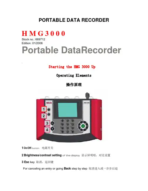
PORTABLE DATA RECORDERH M G 3 0 0 0Stock no.: 669712Edition: 01/2006Portable DataRecorder.Starting the HMG 3000 UpOperating Elements操作原理1On/Off button 电源开关2Brightness/contrast setting of the display显示屏明暗,对比设置3 Esc key取消,返回键For canceling an entry or going Back step by step 取消进入或一步步后退4Shift key 转换键Switches the numpad to a textpad when pressed; the textpad is active only as long as the Shift key is pressed.按转换键,数字板转换成文字板只有按转换键,文字板就能激活5Text/numeric keypad 文本或数字键盘Numbers and letters can be entered via the combination keypad in afashion similar to that of mobile phones.通过联合键盘输入数字与文本,与流行的手机键盘相似Numerals: 0 to 9; “.” (decimal separator) and“-“ (minus)数字:0-9;“.”(十进制分开)“-“ (负数)Text entry : a, b, c, ... x, y, z and A, B, C, ... X, Y, Z ins = insert; del = delete;文本输入:a, b, c, ... x, y, z 和A, B, C, ... X, Y, Z ins=插入del =删除Entry of spaces: shift + ins (simultaneously)空格输入:转换键+插入键(同时)Deletion of characters: shift + del (simultaneously)字符删除:转换键+删除键(同时)6Graphic display 显示图表Display of the menu and operating functions,measured values and measurement curves菜单显示与操作功能,测量值与测量曲线7.5-way navigation key 5通导航键For navigating step by step in the display, Ok key for inputting, concluding,accepting or storing an entry为了在显示中一步步导航,OK键用于输入,终止,接受和保存输入Tip:To accept characters: release the Shift key or press the right arrow of the 5-way navigation key提示:接受字符:释放转换键或按住5通导航键的右箭头Connectors 连接器4 sensor input jacks for up to 8 sensors with an analog signal(channel A – D and E – H*), e.g. for sensors for measuring pressure,temperature or flow rate.The four input jacks can be doubled by plugging in Y-adapters.四个传感器输入接头,加带Y接头可扩展多达八个传感器输入通道A-D和E-H)例如:测量压力的传感器,温度或流速四个输入接头通过插入Y型适配器可增加一倍1 or2 input jacks for-2 digital signals, e.g. for frequency or speed measurements (channel)-1 voltage input ( - 10 V to + 10 V, channel H*)1或2输入接头:-2数字信号,如频率或速度测量(通道I,J)-1电压输入(-10伏特到+10伏特,通道H)Female connector for power supply 电源供应接头1 USB connector 1USB接口1 serial port 1串口H*): C hannel H can be used for sensors with an analog signal as well as for voltage measurements of -10 V to +10 V.通道H能被用作于带有模拟信号的传感器还有-10伏特到+10伏特的电压测量当第一次开启设备,屏幕会出现欢迎字样。
РС-3000 ®© ACELab Contents内容1. 个人计算机 -3000 合成物 (3)1.1. 目的 (3)1.2. 个人计算机 -3000 软件,版本 10.10 (3)1.3. 个人计算机 -3000 合成物随员,版本 10.10 (5)1.4. 担保 (5)1.5. 使用者登记 (6)1.6. 注册的个人计算机 -3000 使用者支持 (6)1.7. 个人计算机 -3000 合成物安装 (6)2. 全世界的考试人为任何的类型硬盘的诊断和修理 (8)2.1. 目的 (8)2.2. 准备为工作 (8)2.3. 数据输出在有个人计算机 -3000 的工作期间在 (8)2.4. 叁数输入因为正被测试的硬盘 (9)2.5. ........................................................................................................ 在操作模态的个人计算机 -3000 (9)2.5.1. 操作模态选择 (9)2.5.2. 看 S.M.A.R.T 。
推进力的叁数 (10)2.5.3. 推进力测试 (11)2.5.4. 控制器测试 (13)2.5.5. 合成物测试 (16)2.5.5.1. 硬盘向上测试成功的因素那"复杂的测试" (18)2.5.6. 背叛再布置 (19)2.5.6.1. 自动机械再布置 (19)2.5.6.2. 手册再布置 (20)2.5.6.3. 再布置解开 (20)2.5.7. 格式 (20)3. 个人计算机 -3000 贝壳 (22)4. 个人计算机- DEFECTOSCOPE Ver. 2.10 (29)4.1. 目的 (23)4.2. 准备为工作 (23)4.3. 有个人计算机-Defectoscope 的工作 (23)4.4. 表演的测试 (24)4.5. 个人计算机- Defectoscope 为硬盘修理使用 (25)4.6. 输出缺点申请结构 (25)5. 西方人数传 "鱼子酱" Arh.4"个人计算机-A313000" "个人计算机-A310100""个人计算机-A38400""个人计算机-一36400" (27)5.1. 目的 (27)5.2. 基本选项为 WD 鱼子酱 Arh.4 推进力修理 (27)5.3. 准备工作 (27)5.4. ..................................................................................................................................... 使用公用程序 (28)5.4.1. 伺服测试 (28)5.4.2. 表面测试. (37)5.4.3. 磁盘片固件地域 (29)5.4.4. 驾驶描述区域 (31)5.4.5. 格式 (31)5.4.6. 合乎逻辑的扫描 (31)5.4.7. S.M.A.R.T。
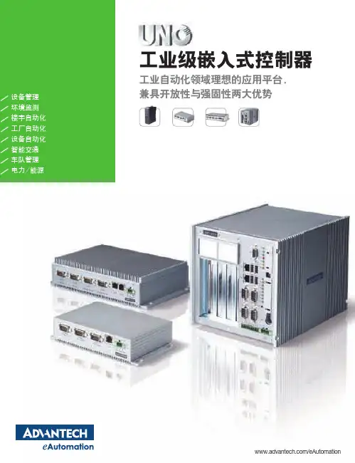
工业级嵌入式控制器工业自动化领域理想的应用平台,兼具开放性与强固性两大优势/eAutomation电力UNO-2050物流UNO-3072设备管理UNO-2182设备自动化UNO-30741通过全球范围众多领域的应用与持续推进证实,研华UNO系列工业级嵌入式控制器是一款功能强大、品质卓越、理想可靠的应用平台。
通用型设计,扩展丰富UNO交 通UNO-2059车队管理UNO-2176门 禁UNO-1019电力 / 能源UNO-21712可靠的模块设计无风扇设计宽操作温度支持多种安装方式结构紧凑开放的操作系统强大的计算能力3UNO: 开放式架构,坚固,无风扇设计坚固,无风扇设计,无风扇设计研华UNO 系列工业级嵌入式控制器结构坚固耐用,适用于各种关键与恶劣环境。
灵活的扩展功能、可靠的品质以及对恶劣环境的适应,源于研华独特的嵌入式、满足工业应用的设计理念及领先的计算机技术。
如果您正在寻找一款兼具强固性与紧凑性的计算平台,那么拥有工业级设计及内建�/O 的UNO 系列绝对是理想的选择。
UNO不仅是一台IPCUNO-1000系列通讯协议转换、执行输出入控制与数据储存等功能的理想控制器。
中通讯协议转换、执行输出入控制与数据储存等功能的理想控制器。
UNO-2000系列紧凑简便,无风扇嵌入式紧凑简便的随用平台,满足不同的应用需要研华UNO-2000们具有板上集成的此是数据网关和控制器的理想解决方案。
UNO-2100 系列高性能,带现场数据量测,低能耗平台,高性能计算机与通讯器研华UNO-2100可据系统要求选用不同等级展。
可据系统要求选用不同等级PC/104扩展功能支持用户扩充任何第三方UNO-3000系列无风扇、、带设计,带有前出线设计,带有出线设计,带有研华UNO-3000可据系统要求选用不同等级前出线设计。
可据系统要求选用不同等级设计。
可据系统要求选用不同等级出线设计。
可据系统要求选用不同等级1.5GHz)),PC�扩展功能支持用户扩充任何第三方研华UNO系列工业级嵌入式控制器结构坚固耐用,适合在任何关键和恶劣环境中使用。
pc3000中文使用教程PC-3000是由俄罗斯著名硬盘实验室-- ACE Laboratory研究开发的商用的专业修复硬盘综合工具。
它是从硬盘的内部软件来管理硬盘,进行硬盘的原始资料的改变和修复。
可进行的操作: 1 伺服扫描 2 物理扫描 3 lba地址扫描 4 屏蔽成工厂坏道(p-list) 5 屏蔽磁头 6 屏蔽磁道 7 屏蔽坏扇区 8 改bios的字(参数) 9 改lba的大小 10 改sn号 11 查看或者修改负头的信息二、PC3000主要用途软硬件综合工具“PC-3000"主要用来专业修复各种型号的IDE硬盘,容量从20MB至200GB,支持的硬盘生产厂家有: Seagate(希捷), Western Digital(西部数据),Fujitsu(富士通), Quantum(昆腾), Samsung(三星), Maxtor(迈拓), Conner, IBM, HP, Kalok, Teac, Daeyoung,and Xebec等。
使用РС-3000有可能修复 50-80% 的缺陷硬盘。
如此高的修复率是通过使用特别的硬盘工作模式来达到的(比如工厂模式),在特别的工作模式下可以对硬盘进行如下操作:内部低级格式化;重写硬盘内部微码模块(firmware);改写硬盘参数标识;检查缺陷扇区或缺陷磁道,并用重置、替换或跳过忽略缺陷的等方式修复;重新调整内部参数;逻辑切断(即禁止使用)缺陷的磁头; S.M.A.R.T参数复位.... 其中,重写内部微码(Firmware)模块对在一些情况下对数据恢复有特别的功效, 如: Maxtor美钻、金钻、星钻系列硬盘加电后不能被正确识别(无磁头杂音);Fujitsu MPG及MPF系列硬盘加电后磁头寻道基本正常,但不能被正确检测到;IBM腾龙系列有磁头寻道声(无杂音),但不能被正确识别; Quantum 硬盘能被检测到,但无法读写;WD EB及BB系列硬盘能被检测到,但无法读写......以上所列的这些故障,一般不属于硬件故障。
巡检管理系统单机版Ver A1.0+操作使用说明书USB驱动安装一、驱动安装第一次安装完软件后,请将巡检器用USB传输线与电脑连接好,系统自动出现如下画面:选择第一个选项(是,仅此一次),单击下一步,出现:选择第二个选项(从列表或指定位置安装),单击下一步,出现:选择在搜索中包括这个位置,点击浏览,选择USB驱动所在的文件夹,单击下一步,出现:单击完成,则USB驱动安装成功。
二、查看设备安装完USB驱动后,您可以在设备管理器中查看所用的串口号,选择我的电脑按右键选择属性,在属性中选择硬件,点击设备管理器,在管理器中选择端口(COM和LPT),出现CP2101 USB to UART Bridge Controller (COM3),则您在软件中应用的串口号则为COM3。
具体过程如下图所示:然后在软件的系统设置里面更改串口号为“com3”,如图:使用说明一、系统设置及使用1.启动系统软件安装完成后,即可在开始|程序|巡检管理系统A1.0 中,单击"巡检管理系统A1.0"项,系统启动,并出现登录窗口。
如果是第一次使用本系统,请选择管理员登录系统,口令为"333",这样您将以管理员的身份登录到本系统。
系统启动后出现如上图示各菜单操作,第一次使用本系统进行日常工作之前,应建立必要的基础数据,如果需要,应修改系统参数。
二、资源设置1.人员钮设置此选项用来对巡检人员进行设置,以便用于日后对巡检情况的查询。
设置人员之前,可先将巡检器清空(把巡检器和电脑传输一次即可),然后将要设置的人员钮按顺序依次读入到巡检器中,把巡检器和电脑连接好,选择"资源设置->人员钮设置"点击采集数据,如下图所示。
电话与地址可以根据需要进行填写,也可以不填。
修改完毕退出即可。
还可以点击"打印数据"将巡检人员设置情况进行打印。
也可以以EXCEL表格的形式将人员设置导出,以备查看。
ACE LaboratorySoftware and hardware complexPC-3000中文说明书第一部分:PC3000-V12主菜单及各模块菜单第二部分:PC3000-V12的工具模块列表第三部分:PC3000-V11使用说明(整理)For diagnostics and repair of and hdd(ATA)PC-3000AT主菜单PC-3000各个模块主菜单一、 富士通V er 4.52(中文说明)1、Servo test 伺服测试1.1 |-------------------------------------------------------------------------------------------------|| The testimg procedure will destroy all user data drive| 这个测试程序将破坏驱动器的全部使用数据| test starting cylinder : xxxxxxxx| 测试开始的柱面: xxxxxxxx| test ending cylinder : xxxxxxxx| 测试结束的柱面: xxxxxxxx| place defecfs to : P-List| 放置坏道到: P-List (空格健变换P-List和Glist)| limit fo grouping into cylinders : xxxxxxxx| 一个柱面超过多少个坏道就封闭:|-------------------------------------------------------------------------------------------------|2、Surface test 表面测试(物理测试)2.1 |------------------------------------------------------------------------------------------------|| test starting cylinder : xxxxxxxxxx| 测试开始的柱面: xxxxxxxxxx| test ending cylinder : xxxxxxxx| 测试结束的柱面: xxxxxxxx| number of passes : 3| 通过的次数: 3 (可在1-x之间选择,默认是3)| number of retry of a defect : 3| 一个坏道重复测试的次数: 3(可在1-x之间选择,默认是3)| critical time test (ms): 300| 测试的临界时间(毫秒):300 (意思是停顿多少毫秒就视为坏道)| perform writing test : NO| 执行写测试: NO/YES (N)不是(y)是默认是(N)| use all heads while testing : yes| 当测试的时候使用全部的磁头: yes (y)是(n)是默认是(yes)| limit fo grouping into cylinders : xxxxxxx| 一个柱面超过多少个坏道就封闭:|------------------------------------------------------------------------------------------------|3、Disc firmware zone 碟片的固件区3.1 Work with the rom 对ROM 工作3.1.1 Review of the disc firmware zone in the ROM检看碟片固件地区的ROM 版本信息3.1.2 Read ROM to file 读ROM 文件3.1.3 Write ROM from file 写ROM 文件3.1.4 Supported ted ROMS 支持的ROM的所有型号3.2 work with disc firmware zone 对碟片固件地区工作3.2.1 Checking of disc firmware structure 检查碟片固件结构3.2.2 disc firmware data writing/reading 碟片固件数据写/读3.2.2.1 Exrtact MP from BASE <-| 从基地提取MP3.2.2.1.1 writing to disc drive <- 写硬盘3.2.2.1.1 writing of modules 写模块3.2.2.1.2 configuration pages writing 写结构页3.2.2.1.2 writing to folder 写文件夹3.2.2.2 Add MP to BASE 添加MP 数据库3.2.2.3 Delete MP from BASE 从数据库册除MP3.3.3 Reading of the modules 读模块3.3.4 Writing of the modules 写模块3.3.5 Regen translator 再生变换器3.3.6 Security subsystem 安全子系统3.3.8.1 show security information 显示安全信息3.3.8.2 Clear passwords 清除密码3.2 software hesds switching off 用软件关闭磁头3.3 spindle stop 主轴停转3.4 work with adaptives4、Disc ID 硬盘的身份(变硬盘的型号和容量)5、Formatting 低级格式化6、Logical scanning 逻辑扫描6.1 |--------------------------------------------------------------------------------------------|| initial LBA position : x| 初始LBA 位置: X| final LBA position : xxxxxxxxxxxx| 结束的LBA 位置: xxxxxxxxxxxx| reversive scanning :NO| 从后面向前面扫描:NO (键入(Y)就从后面向前面扫描)| number of passes : 3| 通过的次数: 3 (可在1-x之间选择,默认是3)| number of retry of a defect : 3| 一个坏道重复测试的次数: 3(可在1-x之间选择,默认是3)| critical time test (ms): 300| 测试的临界时间(毫秒):300 (意思是停顿多少毫秒就视为坏道)| perform writing test : NO| 执行写测试: NO/YES (N)不是(y)是默认是(N)| verify instead of reading : yes| 校验代替读: yes|--------------------------------------------------------------------------------------------|7、S.M.A.R.T. table S.M.A.R.T 表7.1 to review S.M.A.R.T. table 观察S.M.A.R.T 表7.2 S.M.A.R.T. parameters reset 复位S.M.A.R.T. 参数7.3 to load S.M.A.R.T. (external module) 加载S.M.A.R.T. (外部模块)8、Defects table 坏道表8.1 to review defects teble 观察坏道表8.2 Add LBA defects 按LBA 添加坏道表8.3 Add LCHS derects 按柱面/磁头/扇区/长度添加坏道8.4 Add physical sector 按物理扇区添加8.5 Add physical tracks 添加物理磁道8.6 Group into tracks 封闭磁道8.7 import of logical defects table 逻辑坏道表的输入8.8 Erase defects table 删除坏道表9、Automatic mode 自动化模式10、EXIT 退出二、昆腾与迈拓(LE VQ系列)Ver 2.32(中文说明)1、Servo test 伺服测试1.1 |-------------------------------------------------------------------------------------------------|| The testimg procedure will destroy all user data drive| 这个测试程序将破坏驱动器的全部使用数据| test starting cylinder : xxxxxxxx| 测试开始的柱面: xxxxxxxx| test ending cylinder : xxxxxxxx| 测试结束的柱面: xxxxxxxx| place defecfs to : P-List| 放置坏道到: P-List 空格健变换P-List和Glist| limit fo grouping into cylinders : 64| 一个柱面超过多少个坏道就封闭: 64 (可以是2-63)|--------------------------------------------------------|2、Surface test 表面测试(物理测试)2.1 |-------------------------------------------------------------------------------------------------|| test starting cylinder : xxxxxxxxxx| 测试开始的柱面: xxxxxxxxxx| test ending cylinder : xxxxxxxx| 测试结束的柱面: xxxxxxxx| number of passes : 3| 通过的次数: 3 (可在1-x之间选择,默认是3)| number of retry of a defect : 3| 一个坏道重复测试的次数: 3(可在1-x之间选择,默认是3)| critical time test (ms): 300| 测试的临界时间(毫秒):300 (意思是停顿多少毫秒就视为坏道)| perform writing test : NO| 执行写测试: NO/YES (N)不是(y)是默认是(N)| use all heads while testing : yes| 当测试的时候使用全部的磁头: yes (y)是(n)是默认是(yes)| place defects to : P-List| 放置坏道到: P-List 空格健变换P-List和Glist| limit fo grouping into cylinders : 64| 一个柱面超过多少个坏道就封闭: 64 (可以是2-63)|---------------------------------------------------------------------------------------------------------|3、Disc firmware zone 碟片的固件地区3.1 Work with the rom 对ROM 工作3.2 work with disc firmware zone 对碟片固件地区工作3.2.1 Checking of disc firmware structure 检查碟片固件结构3.2.2 disc firmware data writing/reading 碟片固件数据写/读3.2.2.1 Exrtact MP from BASE <-| 从数据库提取MP3.2.2.1.1 writing to disc drive <- 写硬盘3.2.2.1.1 writing of modules 写模块3.2.2.1.2 configuration pages writing 写结构页3.2.2.1.2 writing to folder 写文件夹3.2.2.2 Add MP to BASE 添加MP 到数据库3.2.2.3 Delete MP from BASE 从数据库删除MP3.2.3 Configuration pages reading 构造页读3.2.4 Configuration pages writing 构造页写3.2.5 Reading of the modules 读模块3.2.6 Writing of the modules 写模块3.2.7 Detailed COM log 详细COM log3.2.8 Security subsystem 安全子系统3.2.8.1 show security information 显示安全信息3.2.8.2 Clear passwords 清除密码3.3 Configuration changing 改变内部构造3.4 Load LDR-file to disc RAM 加载LDR 文件到碟片的RAM3.5 spindle stop 主轴停转4、Disc ID 硬盘的身份(硬盘的型号和容量)5、Logical scanning 逻辑扫描5.1 |---------------------------------------------------------------------------------------------|| initial LBA position : x| 初始LBA 位置: X| final LBA position : xxxxxxxxxxxx| 结束的LBA 位置: xxxxxxxxxxxx| reversive scanning : NO| 从后面向前面扫描: NO 键入(Y)就从后面向前面扫描| number of passes : 3| 通过的次数: 3 (可在1-x之间选择,默认是3)| number of retry of a defect : 3| 一个坏道重复测试的次数: 3(可在1-x之间选择,默认是3)| critical time test (ms): 300| 测试的临界时间(毫秒):300 (意思是停顿多少毫秒就视为坏道)| perform writing test : NO| 执行写测试: NO/YES (N)不是(y)是默认是(N)| verify instead of reading : yes| 校验代替读: yes| place defecfs to : P-List| 放置坏道到: P-List 空格健变换P-List和Glist|----------------------------------------------------------------------------------------------|6、S.M.A.R.T. table S.M.A.R.T 表6.1 to review S.M.A.R.T. table 观察S.M.A.R.T 表6.2 to load S.M.A.R.T. (external module) 加载S.M.A.R.T. (外部模块)6.3 S.M.A.R.T. parameters reset 复位S.M.A.R.T. 参数7、Defects table 坏道表7.1 to review defects teble 观察坏道表7.2 Add LBA defects 按LBA 添加坏道表7.3 Add physical sector 按物理扇区添加7.4 Add physical track 按物理磁轨添加7.5 Grouping defects into tracks 封闭坏道到磁轨里7.6 import of logical defects table 逻辑坏道表的输入7.7 Erase defects table 删除坏道表7.8 Defects table export 坏道表输出7.9 Defects table import 坏道表输入7.10 Work with module 06h 对06h 模块工作8、Automatic mode 自动化模式9、SELFSCAN 自我扫描9.1 condition viewing 条件观察9.2 load selfscan 加载自我扫描9.3 start selfscan 起动自我扫描9.4 stop selfscan 停止自我扫描10、EXIT 退出三、西数(EB AB BB JB DA)(中文说明)1、Disk firmware zone 磁盘固件区1.1 Disk firmware zone 磁盘固件区1.1.1 disk firmware surface test 硬盘固件表面测试(硬盘固件物理测试)1.1.2 disk firmware structure test 硬盘固件结构测试及观查1.1.3 disk firmware data read/write 硬盘固件数据读/写1.1.3.1 write FW to the disk 写FW到硬盘1.1.3.2 Add FW to the DATABASE 添加FW到数据库1.1.3.2 Remove FW the DATABASE 册除FW数据库1.1.4 Read modules 读模块1.1.5 write modules 写模块1.1.6 Erase firmware area 清除固件范围1.1.7 Change Servo Area SPT 改变伺服范围1.1.8 Security subsystem 安全子系统1.2 Translator operations 变换器操作1.3 Spindle stop 主轴停转1.4 Change time scale 改变时间等级2、drive description 驱动器描写(改硬盘容量)3、Formatting 低级格式化3.1 Take into account PList and Glist 考虑PList和GList3.2 Take into account Plist 考虑PList3.3 Take into account Glist 考虑GList3.4 Do not Take into account neither PList and Glist PList 和GList 两者都不考虑4、Logical structure scaning 逻辑结构扫描4.1 |----------------------------------------------------------------------------------------------------|| start LBA : x| 开始LBA : X| End LBA : xxxxxxxx| 结束LBA : XXXXXXXX| passes : 3| 通过的次数: 3| carefulness index : 3| 仔细指标| perfrom writing test : NO| 按照写测试| verification instead of reading : yes| 校验代替读|---------------------------------------------------------------------------------------------|5、S.M.A.R.T. table S.M.A.R.T. 表6、Defects table 坏道表6.1 View defects table 观察坏道表6.2 Add physical track 添加物理磁道6.3 import logical defects table 输入逻辑坏道表6.4 clear defects table 清除坏道表6.5 move G-List to P-List G-List 转P-List6.6 Group to tracks 封闭磁道7、Automatic mode 自动模式8、Exit 退出四、迈拓ver1.07 (中文说明)迈拓ver1.20 (中文说明)1、Logicaln scanning 逻辑扫描1.1 |------------------------------------------------------------------------------------------------ || initial LBA position:xxxxxxx| 开始位置| final LBA position:xxxxxxxx| 结束位置| reversive scanning:on| 反向扫描打开、关闭| number of passes:3| 通过的次数| perform writing test:on| 执行写测试打开关闭| verif. instead of reading| 读版本代替| put defects to:p-list| 放置默认列表|---------------------------------------------------------------------------------------------------|2、disc firmware zone 固件区2.1 work with momeory buffer 操作存储缓冲器1.1 memory buffer reading 存储缓冲器读1.2 memory buffer writing 存储缓冲器写2.2 work with sa 操作sa1.1 checking of disc fw structure 检查磁盘固件结构1.2 sa surface checking sa表面检查1.3 reading of the modules 读那个模块1.4 writing of modules 写那个模块1.5 reading modules groups 读全部模块1.6 writing modules groups 写全部模块1.7 sa write test sa写测试1.8 modules repairing 模块修理1.9 transltor regeneration 扇区再生1.10 spindle stop 主轴停转2.3 LDR-file loading 加载ldr文件2.4 LDR-file creation 制造ldr文件2.5 security subsystem 安全系统3、disc id 硬盘id号4、defects table 缺陷表1.1 view p-list 查看p-list1.2 view g-list 查看g-list1.3 move g-list defects to p-list 转移g表到p表1.4 erase g-list 擦除g-list1.5 erase g-list and p-list 擦除g-list和p-list1.6 import from defectoscope 引入探测器5、exit 退出五、西捷(中文说明)六、IBM (中文说明)PC3000-解密版的安装方法:1、PC3000运行于DOS系统。
PC3000中文版说明书PC-3000的使用您购买了一款绝妙的硬盘修复工具――PC3000。
如果您以前常常修理硬盘,很可能你跳过了这一章,然而,如果您没有大量经验的话,作者建议你在开始之前读这一章――“IDE (ATA) HDD。
技术说明,IDE(ATA)HDD修理的基础”这一章包括一段对PC-3000简单的“指引”修理硬盘,不要急于动用专门的技术设备。
首先,任何硬盘都要用PC-3000AT通用测试器(包括在PC3000里)检查一遍。
这能帮你找到缺陷并决定接下来的动作的结果。
为了达到这个目的,把硬盘连接到测试板PC3000PRO上打开电源然后运行PC300AT.exe程序,电源打开后硬盘应该带动梭型马达向上旋转并开始(零轨道搜寻)。
在这个过程中你将听到安放部件的典型声音。
初始化过程结束后硬盘会发送读取信号,如果没有出现这种情况(梭型马达不转或不向上旋转或听到磁头撞击的声音)那么你就要使用Part2.2技术附录中介绍的方法。
硬盘读取检查后(DRDY=DSC=1, BUSY=0),程序会讨善从硬盘描述区域读取数据。
如果得去信号没有还到程序的话,相关的信息就会出现。
这种情况下,就要使用“IDE (ATA) HDD技术说明,IDE (ATA) HDD修理基础”这一章中2.2.1这段介绍的方法。
如果,尽管能受到硬盘读取信号,但不能读取硬盘描述数据(程序送出“硬盘参数没有决定”)或参数读取错误。
这可能意味着不是读取路线有误就是磁盘固件损坏。
(在相关的技术设备帮助下固件的数据可以恢复)然而,可能磁盘没有一个硬盘描写区域(这主要是老的KALOK/ XBEC 型号)或磁盘包含的参数不能用于硬盘操作(例如,Conner CP-3000)在这种情况下就要人工输入参数或从PC3000-AT的数据库中提取才能使测试过程顺利进行。
用PC3000-AT测试后和对它的缺陷作出一各初步的决定后(方法在“IDE (ATA) HDD。

㓈 / 䱰 䰸前言前言感谢您购买Pro-face的GP3000系列可编程人机界面(以下简称为“GP”)和新一代画面和逻辑编程软件“GP-Pro EX”V2.20简体中文版。
在使用这些产品之前,请认真阅读本手册,并妥善保管以备将来参考。
注意(1)这些产品中包括的所有程序和手册的版权均为Digital Electronics Corporation所有。
Digital Electronics Corporation根据“软件操作许可条款”文档(GP-Pro EX的CD-ROM)中的描述,向用户授予这些产品的使用许可。
任何违反上述条款的行为均为日本及国外法规所禁止。
(2)本手册的内容已经过全面审查。
如果您发现任何错误或疏漏,请与我们联系。
(3)对因使用这些产品而造成的损坏或第三方索赔Digital Electronics Corporation不承担任何责任。
(4)本手册中的描述与这些产品的实际功能之间可能存在差异。
有关这些产品的最新信息将在数据文件(如Readme.txt文件等)和其他文档中另行提供。
在使用产品之前,请参考这些资料及本手册。
(5)尽管这些产品包含和显示的信息可能涉及Digital Electronics Corporation或第三方的无形产权或知识产权,但Digital Electronics Corporation不向任何用户和/或其他第三方担保或授权上述产权的使用。
(6)本手册中的规格仅适用于海外产品。
因此,本手册中的产品与其对应的日本产品的规格之间可能存在一定的差异。
Digital Electronics Corporation不承担与第三方知识产权有关的任何责任,也不承担与使用这些产品所包含或显示信息有关的任何责任。
© 2008 Digital Electronics Corporation版权所有,保留所有权利。
Digital Electronics Corporation,2008年6月 有关商标和商标名称权利的信息,请参阅“商标权利”。
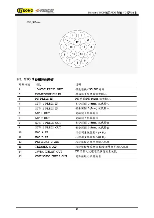
9.3. STO_3壓機控制訊號針腳編號訊號說明1 +24VDC_PRESS_OUT 供應壓機+24V DC電源2 HOMEPOSITION_IN 原始位置感應器訊號輸入3 PU_PRESS_IN PU開關(PU-switch)訊號輸入4 SSW_1_PRESS_IN 安全開關1 (6mm) 訊號輸入5 SSW_2_PRESS_IN 安全開關2 (6mm) 訊號輸入6 MV_1_OUT 電磁閥1訊號輸出7 MV_2_OUT 電磁閥2訊號輸出8 SSW_1_PRESS_OUT 安全開關1 (6mm) 訊號輸出9 SSW_2_PRESS_OUT 安全開關2 (6mm) 訊號輸出10 INC_A_IN 行程測量訊號輸入(A軌)11 INC_B_IN 行程測量訊號輸入(B軌)12 PRESSURE_C_AIN 指針模擬系統壓力輸入訊號13 TRIGGER_C_AIN 指針模擬觸感起振器(偵測壓力差)輸入訊號14 24VDC_DELAY_OUT PU開關之延遲電流供應輸出訊號電源接地之訊號輸出15 GND24VDC_PRESS_OUT9.4. STO_5雙手起動開關控制訊號針腳編號訊號說明1 Nc2 START_1_OUT 起動開關1訊號輸出3 START_1_NC_IN 起動開關1訊號輸入(正常關閉)4 START_1_NO_IN 起動開關1訊號輸入(正常開啟)5 START_2_OUT 起動開關2訊號輸出6 START_2_NC_IN 起動開關2訊號輸入(正常關閉)7 START_2_NO_IN 起動開關2訊號輸入(正常開啟)8 24VDC_DELAY_OUT 控制緊急停止掣之延遲電源供應9 EMERGENCY_1_IN 緊急停止掣1訊號輸入10 EMERGENCY_2_IN 緊急停止掣2訊號輸入11 nc電源接地之訊號輸出12 GND24VDC_PRESS_OUT10 不當使用之錯誤訊息正常ADG錯誤ADG訊號焊接週期階段0>1促動器下壓(焊接前下壓行程)1>2下壓速度漸緩2>3增加功率3>4焊接4>5固化5>6促動器上行裝備隔音罩之正常ADG裝備特殊促動器之ADG焊接週期階段0>2促動器下壓(焊接前下壓行程)1>3下壓速度漸緩2>4增加功率3>5焊接4>6固化5>7促動器上行11 機械維護11.1. 錯誤群組說明錯誤群組002 電箱錯誤003 壓機錯誤004 隔音罩錯誤005 限制值錯誤006 數位控制錯誤007 硬體錯誤008 RS232錯誤009 CANopen錯誤020 限制值警告021 參數值警告11.2. 錯誤代碼詳細說明電箱錯誤(錯誤群組 002:xxx)錯誤代碼優先性說明002:000 低達到最大功率損失(Pv測試)002:001 高電源電壓過低002:002 高Power pack +12V defective002:003 高Minimal level control final stage002:004 高溫度過高002:005 低頻率低於最低值002:006 低頻率高於最高值002:007 低換能器電壓高於最大值002:008 低出力過載002:009 低Full level control of the final stage reached 002:010 低未連接換能器壓機錯誤(錯誤群組 003:xxx)錯誤代碼優先性說明003:000 低測量行程時發生錯誤003:001 低閥門錯誤003:002 低雙手起動開關錯誤003:003 低促動器未回到原始位置Abort 003:004 低安全開關(最後6mm)錯誤003:005 低超過最大焊接週期時間003:006 低焊接過程中斷003:007 低觸感起振器設定錯誤003:008 低超音波起振錯誤003:009 低系統壓力過低隔音罩錯誤(錯誤群組004:xxx)錯誤代碼優先性說明004:000 低安裝錯誤004:001 低開始焊接時工作窗無法開啟004:002 低時間超過而降下工作窗004:003 低時間超過而升起工作窗004:004 低隔音罩門打開004:005 低焊接週期中打開工作窗限制值錯誤(錯誤群組005:xxx)錯誤代碼優先性說明005:000 低超過設定的最大時間005:001 低低於設定的最小時間005:002 低超過設定的最大能量005:003 低低於設定的最小能量005:004 低超過設定的最大出力005:005 低低於設定的最小出力005:006 低超過設定的最大行程005:007 低低於設定的最小行程005:008 低超過設定的最大行程差005:009 低超過設定的最小行程差005:010 低到達設定的良品數數位控制錯誤(錯誤群組006:xxx)錯誤代碼優先性說明006:000 低焊接週期停止006:001 低設定超音波停振1006:002 低設定超音波停振2006:003 低設定重設006:004 低退出外置起動006:005 低需要外製起動006:006 低資料傳遞輸入訊號錯誤硬體錯誤(錯誤群組007:xxx)錯誤代碼優先性說明007:001 高輸出群組1短路007:002 高輸出群組2短路007:003 高輸出群組3短路007:004 高輸出群組4短路007:005 高輸出群組5短路007:006 高輸出群組6短路007:007 低壓力輸入低於1mA007:008 低觸感起振器輸入低於1mA007:009 低數控振幅輸入超過120%或12VRS232錯誤(錯誤群組008:xxx)錯誤代碼優先性說明008:001 低資料溢出錯誤(符號丟失)008:002 低同等性錯誤(同等性符號錯誤)008:003 低結構錯誤(無有效停止符號→bit rate錯誤) 008:004 低傳輸中斷(位元組過長→bit rate錯誤) 008:005 低未連接接收器CANopen錯誤(錯誤群組009:xxx)錯誤代碼優先性說明009:001 低 SDO讀取錯誤(暫停)009:002 低 SDO寫入錯誤(暫停)009:003 低 SDO服務(錯誤參數)009:004 低 SDO無法進入(設定值範圍錯誤)009:005 低 SDO其他錯誤限制警告(警告群組020:xxx)錯誤代碼優先性說明020:000 警告超過設定的最大時間020:001 警告低於設定的最小時間020:002 警告超過設定的最大出力020:003 警告低於設定的最小出力020:004 警告超過設定的最大功率020:005 警告低於設定的最小功率020:006 警告超過設定的最大行程020:007 警告低於設定的最小行程020:008 警告超過設定的最大行程差020:009 警告低於設定的最小行程差參數警告(警告群組021:xxx)錯誤代碼優先性說明021:000 警告資料組是空的 / 未載入資料組021:001 警告警告資料未刪除11.3. 清潔機器注意:清潔與維護須由受過專業訓練之人員操作,開始維護前,確認電源與壓縮空氣源均未接上。
UC-3100 Series Hardware User’s ManualVersion 2.0, September 2019/product© 2019 Moxa Inc. All rights reserved.UC-3100 Series Hardware User’s Manual The software described in this manual is furnished under a license agreement and may be used only in accordancewith the terms of that agreement.Copyright Notice© 2019 Moxa Inc. All rights reserved.TrademarksThe MOXA logo is a registered trademark of Moxa Inc.All other trademarks or registered marks in this manual belong to their respective manufacturers.DisclaimerInformation in this document is subject to change without notice and does not represent a commitment on the part of Moxa.Moxa provides this document as is, without warranty of any kind, either expressed or implied, including, but not limited to, its particular purpose. Moxa reserves the right to make improvements and/or changes to this manual, or to the products and/or the programs described in this manual, at any time.Information provided in this manual is intended to be accurate and reliable. However, Moxa assumes no responsibility for its use, or for any infringements on the rights of third parties that may result from its use.This product might include unintentional technical or typographical errors. Changes are periodically made to the information herein to correct such errors, and these changes are incorporated into new editions of the publication.Technical Support Contact Information/supportMoxa AmericasToll-free: 1-888-669-2872 Tel: +1-714-528-6777 Fax: +1-714-528-6778Moxa China (Shanghai office) Toll-free: 800-820-5036Tel: +86-21-5258-9955 Fax: +86-21-5258-5505Moxa EuropeTel: +49-89-3 70 03 99-0 Fax: +49-89-3 70 03 99-99Moxa Asia-PacificTel: +886-2-8919-1230 Fax: +886-2-8919-1231Moxa IndiaTel: +91-80-4172-9088 Fax: +91-80-4132-1045Table of Contents1.Introduction ...................................................................................................................................... 1-1Overview ........................................................................................................................................... 1-2 Model Description ............................................................................................................................... 1-2 Package Checklist ............................................................................................................................... 1-2 Product Features ................................................................................................................................ 1-2 Hardware Specifications ...................................................................................................................... 1-3 2.Hardware Introduction...................................................................................................................... 2-1Appearance ........................................................................................................................................ 2-2 LED Indicators .................................................................................................................................... 2-6 Monitoring the Function Button (FN Button) Action Using the SYS LED....................................................... 2-6 Reset to Factory Default ............................................................................................................... 2-7 Real-time Clock .................................................................................................................................. 2-7 Placement Options .............................................................................................................................. 2-7 3.Hardware Connection Description ..................................................................................................... 3-1Wiring Requirements ........................................................................................................................... 3-2 Connector Description .................................................................................................................. 3-2 A.Regulatory Approval Statements ....................................................................................................... A-11Introduction The UC-3100 Series computing platform is designed for embedded data acquisition applications. The computer comes with two RS- 232/422/485 serial ports and dual auto-sensing 10/100 Mbps Ethernet LAN ports. These versatile communication capabilities let users efficiently adapt the UC-3100 to a variety of complex communications solutions.The following topics are covered in this chapter:❒Overview❒Model Description❒Package Checklist❒Product Features❒Hardware SpecificationsOverviewMoxa UC-3100 Series computers can be used as edge-field smart gateways for data pre-processing andtransmission, as well as for other embedded data acquisition applications. The UC-3100 Series includesthree models, each supporting different wireless options and protocols.The UC-3100’s advanced heat dissipation design makes it suitable for use in temperatures ranging from -30 to 70°C. In fact, the Wi-Fi and LTE connections can be used simultaneously in both cold and hotenvironments, allowing you to maximize your “data pre-processing” and “data transmission” capability inmost harsh environments.Model DescriptionRegion Model Name Carrier Approval Wi-Fi BLT CAN SD SerialUS UC-3101-T-US-LXVerizon, AT&T, T-Mobile- - - - 1 UC-3111-T-US-LX✓✓- ✓ 2 UC-3121-T-US-LX ✓ 1 ✓ 1EU/APAC UC-3101-T-EU-LX-- - - - 1 UC-3111-T-EU-LX✓- - ✓ 2 UC-3121-T-EU-LX - 1 - 1AU/NZS UC-3101-T-AU-LXTelstra, Optus- - - - 1 UC-3111-T-AU-LX✓- - ✓ 2 UC-3121-T-AU-LX - 1 - 1Package ChecklistBefore installing the UC-3100, verify that the package contains the following items:• 1 x UC-3100 Arm-based computer• 1 x DIN-rail mounting kit (preinstalled)• 1 x Power jack• 1 x 3-pin terminal block for power• 1 x CBL-4PINDB9F-100: 4-pin pin header to DB9 female console port cable, 100 cm• 1 x Quick installation guide (printed)• 1 x Warranty cardNOTE: Notify your sales representative if any of the above items are missing or damaged.Product Features•Armv7 Cortex-A8 1000 MHz processor•Integrated Wi-Fi 802.11a/b/g/n and LTE Cat 1 for the US, EU, APAC, and AUS regions•Bluetooth 4.2 for the US region•Industrial CAN 2.0 A/B protocol supported•-30 to 70°C system operating temperature•Meets the EN 61000-6-2 and EN 61000-6-4 standards for industrial EMC applications•Ready-to-run Debian 9 with 10-year long-term support•Robust Root File System to prevent the system from being bricked due to a firmware update failureHardware SpecificationsNOTE The latest specifications for Moxa's products can be found at https://.2Hardware Introduction The UC-3100 embedded computers are compact and rugged making them suitable for industrial applications. The LED indicators help in monitoring performance and troubleshooting issues. The multiple ports provided on the computer can be used to connect to a variety of devices. The UC-3100 comes with a reliable and stable hardware platform that lets you devote the bulk of your time to application development.In this chapter, we provide basic information about the embedded computer’s hardware and its various components.The following topics are covered in this chapter:❒Appearance❒LED Indicators❒Monitoring the Function Button (FN Button) Action Using the SYS LEDR eset to Factory Default❒Real-time Clock❒Placement OptionsAppearanceUC-3101UC-3101 (US Model)UC-3111 (US Model)UC-3121 (US Version)Dimensions [units: mm (in)] UC-3101UC-3111UC-3121LED IndicatorsRefer to the following table for information about each LED. LED Name Status Function NotesSYSGreen Power is onRefer to the Monitoring the Function Button (FN Button) Action Using the SYS LED section for more details. Red FN button is pressed OffPower is offLAN1/ LAN2 Green 10/100 Mbps Ethernet mode Off Ethernet port is not activeCOM1/ COM2/ CAN1 OrangeSerial/CAN port is transmitting or receiving dataOff Serial/CAN port is not activeWi-FiGreen Wi-Fi connection has been establishedClient mode : 3 levels with signal strength 1 LED is on: Poor signal quality 2 LEDs are on: Good signal quality All 3 LEDs are on: Excellent signal quality AP mode : All 3 LEDs blinking at the same timeOffWi-Fi interface is not activeLTEGreenCellular connection has been established3 levels with signal strength 1 LED is on: Poor signal quality 2 LEDs are on: Good signal quality All 3 LEDs are on: Excellent signal qualityOffCellular interface is not activeMonitoring the Function Button (FN Button) Action Using the SYS LEDThe FN button is used to perform software reboot or to perform firmware restoration. Pay attention to the SYS LED indicator and release the FN button at the appropriate time to enter the correct mode to either reboot your device or restore your device to the default configuration.status is given below: System Status FN Button ActionSYS LED behaviorReboot Press and release within 1 sec Green, blinking until the FN button is releasedRestorePress and hold for over 7 secReset to Factory DefaultFor details on resetting your device to factory default values, refer to the Function Button and LEDIndicators section.Real-time ClockThe real-time clock in the UC-3100 is powered by a lithium battery. We strongly recommend that you do not replace the lithium battery without the help of a Moxa support engineer. If you need to change the battery, contact the Moxa RMA service team.Placement OptionsThe UC-3100 computer can be mounted on to a DIN rail or on a wall. The DIN-rail mounting kit is attached by default. To order a wall-mounting kit, contact a Moxa sales representative.DIN-rail MountingTo mount the UC-3100 on to a DIN rail, do the following:1.Pull down the slider of the DIN-rail bracket located at the back of the unit2.Insert the top of the DIN rail into the slot just below the upper hook of the DIN-rail bracket.tch the unit firmly on to the DIN rail as shown in the illustrations below.4.Once the computer is mounted properly, you will hear a click and the slider will rebound back into placeautomatically.Wall Mounting (optional)The UC-3100 can also be wall mounted. The wall-mounting kit needs to be purchased separately. Refer to datasheet for more information.1.Fasten the wall-mounting kit to the UC-3100 as shown below:e two screws to mount the UC-3100 on to a wall.3 Hardware Connection DescriptionThis section describes how to connect the UC-3100 to a network and connect various devices to the UC-3100.The following topics are covered in this chapter:❒Wiring RequirementsC onnector DescriptionWiring RequirementsIn this section, we describe how to connect various devices to the embedded computer. You must pay attention to the following common safety precautions, before proceeding with the installation of any electronic device:• Use separate paths to route wiring for power and devices. If power wiring and device wiring paths mustcross, make sure the wires are perpendicular at the intersection point.NOTE: Do not run the wires for signal or communication and power wiring in the same wire conduit. To avoid interference, wires with different signal characteristics should be routed separately.• You can use the type of signal transmitted through a wire to determine which wires should be keptseparate. The rule of thumb is that wiring that shares similar electrical characteristics can be bundled together.• Keep input wiring and output wiring separate.• We strongly advise that you label wiring to all devices in the system for easy identification.Connector DescriptionPower ConnectorConnect the power jack (in the package) to the UC-3100’s DC terminal block (located on the bottom panel), and then connect the power adapter. It takes several seconds for the system to boot up. Once the system is ready, the SYS LED will light up.Grounding the UC-3100Grounding and wire routing help limit the effects of noise due to electromagnetic interference (EMI). There are two ways to connect the UC-3100 grounding wire to the ground.1.Through the SG (Shielded Ground, sometimes called Protected Ground):The SG contact is the left-most contact in the 3-pin power terminal block connector when viewed from the angle shown here. When you connect to the SG contact, the noise will berouted through the PCB and the PCB copper pillar to the metal chassis.2. Through the GS (Grounding Screw):The GS is located between the console port and the power connector. When you connect to the GS wire, the noise is routed directly from the metal chassis.Ethernet PortThe 10/100 Mbps Ethernet port uses the RJ45 connector. The pin assignment of the port is shown below:Pin Signal 1 ETx+ 2ETx- 3 ERx+ 4 – 5 – 6 ERx- 7 – 8–Serial PortThe serial port uses the DB9 male connector. It can be configured by software for the RS-232, RS-422, or RS-485 mode. The pin assignment of the port is shown below:Pin RS-232 RS-422 RS-4851 DCD TxD-(A) –2 RxD TxD+(A) –3 TxD RxD+(B) Data+(B)4 DTR RxD-(A) Data-(A) 5GND GND GND 6 DSR –– 7 TRS – – 8 CTS – – 9–––CAN Port (UC-3121 only)The UC-3121 comes with a CAN port which uses the DB9 male connector and is compatible with the CAN 2.0A/B standard. The pin assignment of the port is shown below:Pin Signal Name1 –2 CAN_L3 CAN_GND4 – 5CAN_SHLD6 GND7 CAN_H8 – 9CAN_V+SIM Card SocketThe UC-3100 comes with two nano-SIM card sockets for cellular communication. The nano-SIM card sockets are located on the same side as the antenna panel. To install the cards, remove the screw and theprotection cover to access the sockets, and then insert the nano-SIM cards into the sockets directly. You will hear a click when the cards are in place. The left socket is for SIM 1 and the right socket is for SIM 2. To remove the cards, push the cards in before releasing them.RF ConnectorsThe UC-3100 comes with RF connectors to the following interfaces.Wi-FiThe UC-3100 comes with a built-in Wi-Fi module (UC-3111 and UC-3121 only). You must connect theantenna to the RP-SMA connector before you can use the Wi-Fi function. The W1 and W2 connectors are interfaces to the Wi-Fi module.BluetoothThe UC-3100 comes with a built-in Bluetooth module (UC-3111 and UC-3121 US region only). You must connect the antenna to the RP-SMA connector before you can use the Bluetooth function. The W1 connector is the interface to the Bluetooth module.CellularThe UC-3100 comes with a built-in cellular module. You must connect the antenna to the SMA connector before you can use the cellular function. The C1 and C2 connectors are interfaces to the cellular module.For additional details refer to the UC-3100 datasheet.SD Card Socket (UC-3111 and UC-3121 US only)The UC-3111 comes with a SD-card socket for storage expansion. The SD card socket is located next to the Ethernet port. To install the SD card, remove the screw and the protection cover to access the socket, and then insert the SD card into the socket. You will hear a click when the card is in place. To remove the card, push the card in before releasing it.Console PortThe console port is an RS-232 port that you can connect to with a 4-pin pin header cable (in the package).You can use this port for debugging or firmware upgrade.PinSignal1 GND2 NC3 RxD4 TxDUSBThe USB port is a type-A USB 2.0 version port, which can be connected with a USB storage device or other type-A USB compatible devices.ARegulatory Approval StatementsThis device complies with part 15 of the FCC Rules. Operation is subject to the following two conditions: (1) This device may not cause harmful interference, and (2) this device must accept any interference received, including interference that may cause undesired operation.Class A: FCC Warning! This equipment has been tested and found to comply with the limits for a Class A digital device, pursuant to part 15 of the FCC Rules. These limits are designed to provide reasonable protection against harmful interference when the equipment is operated in a commercial environment. This equipment generates, uses, and can radiate radio frequency energy and, if not installed and used in accordance with the instruction manual, may cause harmful interference to radio communications. Operation of this equipment in a residential area is likely to cause harmful interference in which case the users will be required to correct the interference at their own expense.European Community。
工控机内部参数更改流程登陆板子:telnet IP设置IP:ifconfig eth0 192.168.1.100Route add default gw 192.168.1.1一、修改ip地址,Jffs2文件夹下networkchange.confvi networkchange.conf然后按下键盘“i”,进入修改模式,进行修改。
修改完毕后,按下“ESC”,然后输入“:Wq”(表示保存二、修改终端号,网点号。
jffs2文件夹下flash盘中machineconfig.confvi /jffs2/flash/machineconfig.conf修改是先cd jffs2cd flashvi machineconfig.conf按‘I’键修改修改好后,按ESC键,再‘:’,最后WQ保存没有修改好,已经按ESC键,则再‘:’,最后Q!重新修改。
Cd flashCat machineconfig.conf看蹲位、服务器IP、arrangei=10.255.254.19调度中心IP等等信息。
如有误差:vi machineconfig.conf按‘I’键修改修改好后,按ESC键,再‘:’,最后WQ保存修改有误,已经按ESC键,再‘:’,最后Q!重新修改。
备注:在修改参数之前先把进程杀掉:killCd jffs2 cd flash cd faildir 然后ls 列出看那个文件值大?然后rm删掉那个常用命令:cd 是进入文件夹cd .. 是返回上层目录ps –a (列出进程)kill 是杀掉进程chmod –R 777 jffs2设置最大权限cd jffs2 ./main &(重新运行程序)reboot –f(重启工控机)cat (查看数据)ls (列出文件)修改改时间:date 月日时间年份HwclockHwclock -w进入工控机用超级终端设57600和硬件(无)telnet 里面设置PS显示所有进程。
[分类:受限制]Check Point版权声明©2020Check Point Software Technologies Ltd.保留所有权利。
本产品及相关文档受版权保护,并且凭限制其使用、复制、分发及反编译的许可进行分销。
未经Check Point的事先书面授权,不得对本产品或相关文档的任何部分,以任何形式或任何方式进行复制。
在本手册编制过程中已非常谨慎,但Check Point不对任何错误或疏漏承担责任。
本出版物及其中所述功能如有更改,恕不另行通知。
限制权利图注:政府的使用、复制或纰漏须符合DFARS252.227-7013和FAR52.227-19的“技术数据和计算机软件权利”一条中第(c)(1)(ii)款规定的限制。
商标:参考版权页以获取我们的商标清单。
参考第三方版权声明以获取相关版权和第三方许可的清单。
重要信息最新软件我们建议您安装最新版软件,以获得最新的完善功能、更好的稳定性、更高的安全级别,并防止发展中的新攻击入侵。
认证有关Check Point产品的第三方独立认证,请参见Check Point认证页面。
Check Point3000设备如需更多有关此版本的信息,请参见主页。
此文档的最新版本请打开网页浏览器中此文档的最新版本。
请下载此文档(PDF格式)的最新版本。
反馈Check Point一直在致力于完善其文档。
请发送您的意见给我们,以帮助我们不断改进。
修订历史目录安全和环保声明7合规信息9符合性声明9引言14欢迎14 3000设备概述14装运箱内容物15术语15将3000设备安装于机架16设备物理规格16设备通风口16配置3000设备18启动设备18可用软件映像18初始配置18创建网络对象18高级配置18连接至3000设备CLI19 3000设备硬件20前面板20后面板22在3100/3200设备中安装电源配适器固定夹22双冗余BIOS25更换和升级组件26恢复出厂默认设置27通过Gaia门户进行恢复27通过启动菜单恢复27通过Gaia Clish进行恢复28注册和支持29注册29支持29如何进阶?29安全和环保声明请在设置或使用设备前阅读以下警告。
第五章测量样品J测量窗口 100J校准 102 设置新标度 102标度应用 105标度编辑 107标度删除 108标度保存 109标度读取 110标度表 111 J测量 112 距离 112面积 138角度 140计算 143快捷菜单 148测量数据的确认 160 J工具功能 167 文本设置 167网格线设置 168标尺设置 168日期设置 169选项设置 170打印 171保存数据 172KH-3000V/KH-3000VD用户手册99KH-3000V/KH-3000VD用户手册100在菜单(MENU )中点击测量(MEASUERMENT )。
在测量窗口中有2种图标:测量图标,可以计算目标的长度、面积、角度等等;工具图标,可以改变屏幕的显示内容等等。
测量图标工具图标测量图标KH-3000V/KH-3000VD用户手册101工具图标KH-3000V/KH-3000VD用户手册102校准为了获得精确的测量数据,必须预先校准标尺KH-3000可以存储30个标尺数据,这些已记录的标尺同样可以存储在记忆卡里。
什么是标尺?当测量样品的尺寸时,是根据相距的像素来计算的,而像素的尺寸会随放大倍率的改变而改变,因而要得到观测目标的精确尺寸,必须在测量前先设定标尺。
设定一个新标尺根据不同的镜头类型、放大倍率来设定标尺数据和单位,这些数据可以被存储在数据库中。
设置数据 说明NO 显示已设定标尺的编号PIX 在标尺设定屏幕上显示像素数目,当点击PIX 时,一个数字键盘会显示,改变所需要的像素数目,标尺的长度会根据像素数目的改变而改变,(从1到1600,出厂设置为50)LENGTH在标尺设定屏幕上显示像素数目,当点击LENGTH 时,一个数字键盘会显示,改变所需要的像素数目,标尺的长度会根据像素数目的改变而改变,(从0.001到9999.999,出厂设置为50)UNIT 选择和设置数值单位,(出厂设置为pix ,inc ,mm ,cm ,μm 和nm ) H VIEW 在屏幕上显示水平视图距离,数值会被自动计算,这个计算数值不能被改变 1 PIXEL 显示已标定的像素,数值会被自动计算,这个计算数值不能被改变 NOTE 设定标尺数据的备注,最多可输入24个字符1. 在菜单中点击测量MEASUREMENTKH-3000V/KH-3000VD用户手册103显示测量窗口显示标尺说明如果您知道像素的精确尺寸,可以点击Numerical 输入数值显示标尺设置屏幕在标尺调节中点击鼠标右键,显示快捷菜单。
意大利克莱门特中央空调W3000用户手册C0240101-07-04-GB1.摘要1.摘要 (1)2.使用用户界面 (2)3.菜单描述 (3)3.1符号 (3)4.机组信息 (4)5.机组ON 和OFF开关 (4)5.1机组开/关 (4)5.1.1开/关按钮 (4)5.1.2开/关参数 (4)5.1.3外部数字量输入的开/关命令 (4)5.1.4定时调节设定 (5)5.1.5监控协议 (5)5.2设定操作模式 (6)5.2.1参数 (6)5.2.2外部数字量输入夏季/冬季选择命令 (6)5.2.3外部数字量输入选择热回收功能 (6)5.2.4监控协议 (7)5.3设定点设置 (7)6.输入和输出的数值和状态 (7)7.时钟 (7)7.1定时调节设定 (7)8.用户程序 (9)8.1调节 (9)8.1.1分段调节模 (9)8.1.2快速自整定调节模式 (11)8.1.3螺杆式压缩机的连续调节模式 (16)8.2热回收 (17)8.3节能制冷 (18)8.3.1节能制冷启动百分比 (18)8.3.2节能制冷低温控制 (18)8.3.3风扇分步的节能制冷调 (18)8.3.4风扇连续控制的节能制冷调节 (18)9. 工厂程序 (19)10.报警 (19)11. 附件附件A报警表W3000控制终端软件由电子签名掌控, 换言之该软件只能在克莱门特公司提供的平台上进行操作.2. 使用用户界面两种用户界面可供选择W3000W3000紧凑型根据安装的用户界面不同,控制空调机组及获取系统信息的功能键也会有所增减.KeyDescriptionW3000, W3000 baseW3000 compact[MENU key]: 进入主菜单.[UP key]: 滚动任务单设定控制参数数值[DOWN key]: 滚动任务单设定控制参数数值[ENTER key]: 确认数据设定[ESC key]: 如果操作处于任务栏深层栏位的话返回上一级,或者 返回系统控制界面[ALARM key]: 显示警告并复位它们--- [SETPOINT key]: 直接进入设定菜单---[ON/OFF key]: 启动/关闭W3000还有以下的显示灯:SymbolColourDescriptionGreen如果指示灯持续显示表示压缩机正常工作,闪烁表明压缩机有启动需求Red压缩机因压缩机或回路警告暂定工作 Green 压缩机处于制冷状态 Green 回路处于节能制冷状态 Green 压缩机处于热泵状态Green 如果指示灯持续显示说明回路处于热回收状态,闪烁时表明存在热回收警报Green如果指示持续显示表示回路处于除霜状态, 闪烁表明处于除霜结束前的吹干水滴状态显示面右侧红色指示灯亮表明存在一个警告3 菜单描述进入任务表的树形图如下:菜单简要描述如下:“Unit Menu”菜单包括温度,压力和回路状况.“Setpoint menu”菜单用来设定各种可用功能的功能键.“I/O menu”显示数字量输入的状态和模拟量输入数值.同时也显示数字量输出的状态和提供给模拟量输出的电压值.如果有扩展板的话(取决于结构参数),模拟量输入/输出也会显示. “Clock menu”菜单中,存在时钟板的情况下可以设置日期和时间.“User menu”菜单中设定和显示与客户程序相关的参数.“Manufacturer menu” 菜单中设置和显示重要的的系统参数.3.1 符号符号描述Off 机组/回路关闭Ch nr 制冷回路没有响应调温器的降温需求Ch 制冷回路响应调温器的降温需求Ch + R 制冷回路及热回收系统响应调温器的需求Hp nr 热泵回路没有响应调温器的需求Hp 热泵回路响应调温器的需求R nr 仅热回收系统回路没有响应调温器的需求R 仅热回收系统响应调温器的需求Pd 回路处于Pump-down状态Defr 回路处于除霜模式Drip 回路处于吹干模式Bands 定时设定功能激活Fcool 系统处于节能制冷模式Limit 能量限制功能启动(要求限制)4. 机组信息机组菜单包含了关于机组与回路的信息该信息诸如温度,压力及回路状态等将在下文中详细阐述.5. 系统启动与关闭用户可以在主菜单进行机组的启动与关闭.5. 1 机组启动与关闭注意:机组于开机前需连接电源八小时以上,如若不然,不能享受保修待遇启动/关闭机组的方法有以下几种:5.1.1 ON/OFF 按钮z启动: 按下启动/关闭按钮z关闭: 按启动/关闭按钮5.1.2 ON/OFF参数“Com: On/Off”参数信息显示于”main task”(主菜单)上. “Off”表示系统已关闭, “On”表示系统已开启.z开启: 按“Enter”(确定)键进入“On and Off”参数控制菜单,按“Up”(上)和“Down”(下)键直至“On”出现. 按下“Enter” (确定)键进行确认.如果“On”持续显示则表示系统已经开启。
KH3000G无纸记录仪使用手册(Ver1.2)前言感谢购买本公司的产品!本手册是关于公司3000G无纸记录仪仪表的功能、设置、接线方法、操作方法等的说明书。
在您操作使用之前请先阅读本说明书,阅读完后,请妥善保管于随时可以翻阅的地方,以便您在操作时可以参照。
注意本系列产品品质与功能不断提升,若实物与本手册内容有不符的地方,请以实物为准,或与技术人员联系,感谢您的支持。
阅读指南〖手册目标〗本手册将向用户介绍3000G无纸记录仪的功能、操作方法等,并帮助用户迅速熟悉并使用仪表。
通过本手册,您将对本公司3000G无纸记录仪有一个全面的了解,并为您提供该仪表使用过程中遇到问题的解决办法以及获得资源和帮助的渠道。
〖手册构成〗第1章:产品使用前;第2章:①3000G产品的概述②指导用户正确安装仪表;第3章:仪表接线说明;第4章:仪表操作指南;第5章:仪表界面参数说明;第6章:仪表系统参数功能说明;第7章:仪表功能描述;第8章:仪表数据存储操作与分析说明;第9~12章:应用组态举例与单位。
〖手册约定〗【注意】的意思是请读者注意哪些需要注意的事项;【警告】的意思是请读者千万注意某些事项,否则将造成严重错误。
目录1、使用前 (1)1.1开箱 (1)1.2配件清单 (1)1.3注意事项 (1)2、3000型无纸记录仪产品规格 (2)2.1概述 (2)2.1.1主要特点 (2)2.1.2技术指标 (2)2.1.3仪表型号定义 (3)2.2仪表安装 (4)2.2.1安装环境 (4)2.2.2安装尺寸 (4)2.2.3安装方式 (5)2.2.4接线端子说明 (5)2.2.5面板说明 (6)3、接线说明 (7)3.1电源接线 (7)3.2报警输出接线 (8)3.3微型打印机接线 (8)3.4信号输入接线 (8)3.5通讯接线 (9)4、操作指南 (10)4.1仪表参数设置方法 (10)4.1.1字符串型参数的设置方法 (10)4.1.2密码型参数的设置方法 (10)4.1.3整数型和定点数型参数的设置方法 (11)4.1.4定点数型参数小数点的设置方法 (11)5、画面说明 (12)5.1实时曲线界面 (12)5.2实时圆图界面 (12)5.3概貌显示界面 (13)5.4特大数显界面 (13)5.5流量显示界面 (14)5.6棒图显示界面 (14)5.7历史曲线界面 (14)5.8历史圆图界面 (15)5.9微型打印机操作界面 (15)5.10系统配置界面 (16)5.11系统组态界面 (16)6、系统组态参数设置说明 (18)6.1系统参数说明 (18)6.2模拟量输入参数说明 (18)6.3运算通道参数说明 (19)6.4流量运算参数说明 (20)6.5折线运算参数说明 (21)6.6通道参数说明 (21)6.7通道报警参数说明 (22)6.8累积报表参数说明 (22)7、功能说明 (24)7.1数字滤波 (24)7.2报警输出 (24)7.3打印功能 (24)7.4流量积算 (24)7.5.1流量累积组态流程 (24)7.5.2流量计算数学模型 (25)7.5.3累积系数的组态 (26)7.5.4补偿类型的组态 (26)7.5.5过热蒸汽补偿模式 (26)7.5.6饱和蒸汽补偿模式 (26)7.5.7一般气体补偿模式 (26)7.5.8线性温度补偿模式 (27)7.5.9流量累积批量输出功能 (27)8、数据导出及分析 (29)8.1数据的导出 (29)8.2数据分析软件的使用 (29)9、附录1流量累积应用组态举例 (32)10、附录2运算通道应用组态举例 (39)11、附录3折线运算应用组态举例 (40)1、使用前1.1开箱开箱时注意不要向内部施加过大的力,箱体应朝上,从箱体封口处打开。