EB-PVD制备热障涂层完整介绍
- 格式:doc
- 大小:139.00 KB
- 文档页数:8
EB -PVD 及其制备功能涂层的研究进展EB -PV D Technology and Development in Preparing Protectio n Coatings滕 敏,孙 跃,赫晓东,李明伟(哈尔滨工业大学复合材料与结构研究所,哈尔滨150080)TENG Min ,SUN Yue ,HE Xiao -dong ,LI M ing -w ei(Center for Composite m aterials ,H arbin Institute of Technology ,H arbin 150080,China )摘要:介绍了电子束物理气相沉积(EB -P VD )设备的结构、工艺技术特点等,重点介绍了EB -P VD 技术在制备各种防护涂层方面所取得的成果及研究进展。
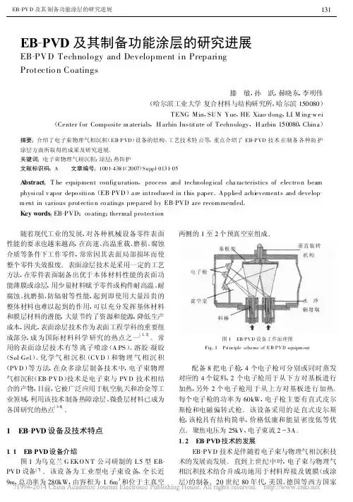
关键词:电子束物理气相沉积;涂层;热防护文献标识码:A 文章编号:1001-4381(2007)Suppl -0131-05A bstract :T he equipment config uration ,process and technolog ical cha racteristics of electro n beam physical v apor depo sition (EB -PVD )a re introduced in this paper .Applied achievements and develop -m ent in various protectio n co atings prepared by EB -PVD are recom mended .Key words :EB -PVD ;co ating ;thermal pro tection 随着现代工业的发展,对各种机械设备零件表面性能的要求也越来越高,在高速、高温重载、磨损、腐蚀介质等条件下工作零件,常常因其表面局部损坏而使整个零件失效报废。
北京航空材料研究院硕士学位论文EB-PVD氧化锆纳米结构热障涂层研究姓名:***申请学位级别:硕士专业:材料物理与化学指导教师:***200612202)在气冷条件相当的情况下,压气机室进气口温度一样,有热障涂层的发动机热端部件其基体承受的温度较低。
有研究表明,降低温度能大大提高材料的疲劳寿命,故而提高发动机部件的使用寿命{9];3)当气冷条件相当,基体合金工作温度一样的情况下,由于使用热障涂层的发动机可以承受更高温度的燃烧气体,因此可以提高发动机的推力,增加推重比。
图L2热障涂层技术为航空发动机带来的综合效益示意181总之,热障涂层技术是发展高推重比航空发动机的关键技术之一,在目前及今后~个阶段,在先进航空发动机叶片上使用热障涂层技术是一个被普遍接受的共识。
1.2热障涂层体系热障涂层的基本思路是在合金基体上涂覆或沉积陶瓷涂层以达到隔热的作用,但是由于陶瓷和基体合金晶格不匹配,且热膨胀系数差别较大,涂层和基体的连接不会太好,伴随着热循环过程中产生的应力,容易造成涂层的失效。
因此,在基体和陶瓷层之间还应有一层粘结层来增强涂层的结合力,缓解涂层使用过程中的热应力。
基体、粘结层和陶瓷层构成了一个复杂的材料体系。
该材料体系中各部分的作用可如图1.3表示:基体合金主要是承载,需具备良好的高温力学性能;粘结层用于过渡合金基体和陶瓷层,减小两者热性能参数的不匹配,且在热循环过程中能够在其表面生成一溥层热生长氧化物层(Thermalgownoxide,简称TGO),阻止氧离子和腐蚀介质的扩散,保护基体合金,减少高温氧化和腐蚀;陶瓷层用来隔热,当带有热障涂层的热端部件(如发动机动叶)达到稳态传热时,在热障涂层两端能够产生一个温降,从而降低基体高温合金表面的温度I81。
图1.3经典热障涂层体系及各部分作用[8I1.2.1粘结层粘结层位于陶瓷层和基体之间,对热障涂层体系的性能有着十分重要的影响。
由于YSZ陶瓷层在高温下是氧离子导体,对氧离子的扩散没有阻隔作用【101,因此粘结层需具备优良的抗高温氧化性能,氧化膜的生长动力学常数应较低。

2023 年第 43 卷航 空 材 料 学 报2023,Vol. 43第 4 期第 17 – 24 页JOURNAL OF AERONAUTICAL MATERIALS No.4 pp.17 – 24铂铝黏结层体系EB-PVD热障涂层的热循环行为贺文燮1, 甄 真2, 王 鑫2, 彭 超2, 牟仁德2,何利民2, 黄光宏2, 许振华2*(1.贵阳航发精密铸造有限公司 ,贵阳 550014;2.中国航发北京航空材料研究院 航空材料先进腐蚀与防护航空科技重点实验室,北京 100095)摘要:在镍基单晶高温合金基体上采用化学气相沉积法制备铂铝金属黏结层,并采用电子束物理气相沉积制备氧化钇部分稳定化的氧化锆(YSZ)陶瓷面层。
研究了黏结层相组成对热障涂层循环氧化行为的影响,借助扫描电子显微镜(SEM)、X射线能谱分析(EDS)和X-射线衍射分析(XRD)等方法分析涂层的相结构、显微组织和化学成分。
结果表明:黏结层主要成分包括Ni、Al、Pt、Co和Cr 元素并由β-(Ni,Pt)Al相和PtAl2相组成;经热循环测试后,涂层在热生长氧化物(TGO)和黏结层内部及其界面可能出现剥离;随着热暴露时间的延长,TGO层处的残余应力总体上呈现出逐渐减小的演变趋势;控制铂铝黏结层前驱体活性、Pt/Al元素含量、抑制脆性PtAl2相生成、改善TGO层/黏结层界面韧性和降低TGO层应力应变水平可有效延长铂铝黏结层体系热障涂层的热循环寿命。
关键词:热障涂层;热循环;相结构;界面;失效doi:10.11868/j.issn.1005-5053.2023.000058中图分类号:TG174.4 文献标识码:A 文章编号:1005-5053(2023)04-0017-08Thermal cycling behavior of EB-PVD TBCs with Pt modifiedaluminide bond coatHE Wenxie1, ZHEN Zhen2, WANG Xin2, PENG Chao2, MU Rende2,HE Limin2, HUANG Guanghong2, XU Zhenhua2*(1. Guiyang AECC Power Precision Casting Co., LTD, Guiyang 550014, China;2. Aviation Key Laboratory of Science and Technology on advanced Corrosion and Protection for Aviation Material,AECC Beijing Institute of Aeronautical Materials,Beijing 100095, China)Abstract:The(Ni, Pt)Al bond coats were prepared on the surface of nickel base single crystal superalloy by chemical vapor deposition(CVD), and then YSZ ceramic coats were directly deposited on the surface of bond coats by electron beam physical vapor deposition(EB-PVD).The influence of phase constituent of bond coat on the cyclic oxidation behavior of (Ni, Pt)Al/YSZ thermal barrier coatings was investigated in detail. The phase structure, morphology and chemical composition of the coatings were analyzed. The experimental results show that the bond coat is mainly composed of β-(Ni,Pt)Al and PtAl2 phases and the contents of the as-deposited bond coat are primarily including Ni, Al, Pt, Co and Cr elements. The spallation location of the TBCs probably occurs at the interface of TGO layer and bond coat, inside of TGO layer and within the bond coat. After thermal cycling test, it is found that the spallation may occur in the interior and interface of TGO and adhesive layer. With the extension of thermal exposure time, the residual stress located at the TGO layer decreases gradually in total. Therefore, controlling the precursor activity, Pt/Al element content, inhibiting the formation of brittle PtAl2 phase, improving the interfacial toughness of TGO layer/bonding layer, and reducing the stress-strain level of TGO layer are important ways to extend the thermal cycling life of(Ni, Pt)Al/YSZ thermal barrier coatings. Key words: thermal barrier coatings;thermal cycling;phase structure;interface;failure热障涂层技术是一种将耐高温、高隔热陶瓷材料沉积在合金基体表面的高温防护技术,其可以有效降低热端部件表面温度,提高基体材料耐高温氧化腐蚀性能,提升发动机的推重比和热效率,延长高温高应力状态下热端部件的使用寿命[1-2]。
采用EB-PVD技术制备两种多分层热障涂层的研究刘亮;张华芳;高巍;雷新更;崔向中;郑玉峰【期刊名称】《材料导报》【年(卷),期】2012(026)020【摘要】基于电子束物理气相沉积(EB-PVD)技术,设计并分别采用离子束辅助沉积法和低转速法制备了两种具有分层结构的热障涂层(TBCs),对陶瓷层引入层状结构后的组织结构与性能进行了研究.结果表明,层状结构的引入带来大量平行于沉积面的分层界面和相邻分层间的密度调制变化.层状结构TBCs的占优取向由(100)逐渐变化到(111),但仍都形成了不可转变的四方相(t(’))结构.依据分层结构本身的差异和分层界面所处位置的不同,低转速分层试样具有更好的抗氧化性能,但离子辅助分层试样具有明显更长的热循环寿命.【总页数】4页(P21-24)【作者】刘亮;张华芳;高巍;雷新更;崔向中;郑玉峰【作者单位】哈尔滨工程大学生物医用材料与工程研究中心,哈尔滨150001;中航工业北京航空制造工程研究所高能束流加工技术重点实验室,北京100024;中航工业北京航空制造工程研究所高能束流加工技术重点实验室,北京100024;中航工业北京航空制造工程研究所高能束流加工技术重点实验室,北京100024;中航工业北京航空制造工程研究所高能束流加工技术重点实验室,北京100024;中航工业北京航空制造工程研究所高能束流加工技术重点实验室,北京100024;哈尔滨工程大学生物医用材料与工程研究中心,哈尔滨150001;北京大学工学院,北京100871【正文语种】中文【中图分类】TG174.453【相关文献】1.EB-PVD热障涂层皱曲问题研究进展 [J], 何伶荣;张坤;陈光南2.钛合金基体EB-PVD热障涂层的制备与初步研究 [J], 何博;李飞;周洪;姚振中;孙宝德3.EB-PVD方法制备热障涂层热循环性能研究 [J], 姚振中;武洪臣;冯建基;雷新更4.力学载荷条件下EB-PVD热障涂层损伤行为研究 [J], 牟仁德;王占考;陆峰;舒焕烜5.EB-PVD热障涂层粘结层/TGO界面性能的研究进展 [J], 刘林涛;张勇;吕海兵;何飞因版权原因,仅展示原文概要,查看原文内容请购买。
![一种利用EB-PVD技术制备的高熵氧化物超高温热障涂层及其方法[发明专利]](https://uimg.taocdn.com/d06ea4f6b04e852458fb770bf78a6529647d358f.webp)
专利名称:一种利用EB-PVD技术制备的高熵氧化物超高温热障涂层及其方法
专利类型:发明专利
发明人:赵晓峰,张显程,郭芳威,石俊秒,范晓慧,杨凯,王卫泽,陆体文,刘利强,孙子豪
申请号:CN202111182239.1
申请日:20211011
公开号:CN114000107A
公开日:
20220201
专利内容由知识产权出版社提供
摘要:本发明提供一种利用EB‑PVD技术制备的高熵氧化物超高温热障涂层及其方法,该方法包括以下步骤:1)分别称取ZrO2、Y2O3、Ta2O5、Nb2O5和Yb2O3;2)将原料进行湿法球磨,烘干,第一次烧结,造粒;3)经冷等静压制成陶瓷胚体,第二次烧结,得到陶瓷靶材;4)提供一种合金基体,进行磨抛处理,喷砂粗化,清洗,利用APS技术在表面制备NiCoCrAlY粘结层;5)将合金基体装入高温合金夹具,将陶瓷靶材放入电子束物理气相沉积设备中,用高能电子束熔化靶材使得蒸发的靶材原子沉积到粘结层表面,即得。
根据本发明制备的热障涂层能够在1600℃高温下仍保持四方相,可应用于下一代航空发动机热障涂层材料。
申请人:上海交通大学,华东理工大学,中国科学院上海硅酸盐研究所
地址:200240 上海市闵行区东川路800号
国籍:CN
代理机构:上海智信专利代理有限公司
代理人:余永莉
更多信息请下载全文后查看。
电子束物理气相沉积(EB-PVD)技术制备热障涂层技术黄升摘要:本文介绍电子束物理气相沉积(EB-PVD)制备热障涂层技术,结合发展历程综述其技术原理、设备构造及工艺特点。
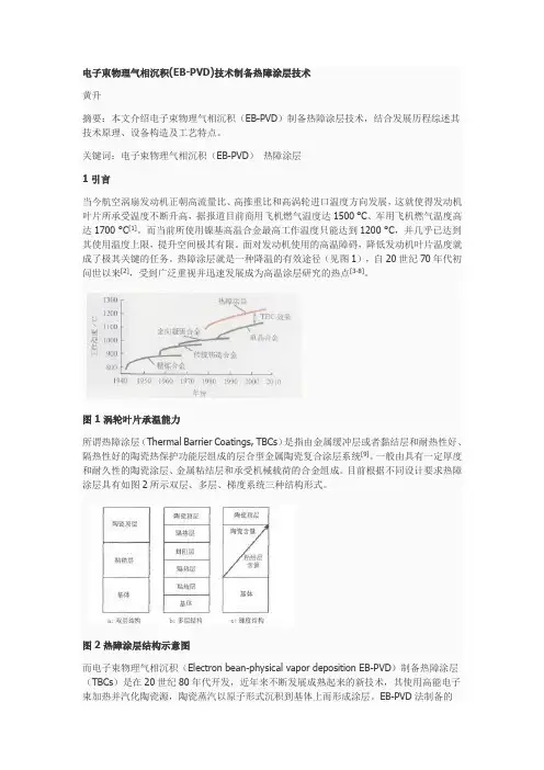
关键词:电子束物理气相沉积(EB-PVD)热障涂层1 引言当今航空涡扇发动机正朝高流量比、高推重比和高涡轮进口温度方向发展,这就使得发动机叶片所承受温度不断升高,据报道目前商用飞机燃气温度达1500 °C、军用飞机燃气温度高达1700 °C[1]。
而当前所使用镍基高温合金最高工作温度只能达到1200 °C,并几乎已达到其使用温度上限,提升空间极其有限。
面对发动机使用的高温障碍,降低发动机叶片温度就成了极其关键的任务。
热障涂层就是一种降温的有效途径(见图1),自20世纪70年代初问世以来[2],受到广泛重视并迅速发展成为高温涂层研究的热点[3-8]。
图1 涡轮叶片承温能力所谓热障涂层(Thermal Barrier Coatings, TBCs)是指由金属缓冲层或者黏结层和耐热性好、隔热性好的陶瓷热保护功能层组成的层合型金属陶瓷复合涂层系统[9]。
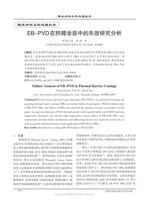
一般由具有一定厚度和耐久性的陶瓷涂层、金属粘结层和承受机械载荷的合金组成。
目前根据不同设计要求热障涂层具有如图2所示双层、多层、梯度系统三种结构形式。
图2 热障涂层结构示意图而电子束物理气相沉积(Electron bean-physical vapor deposition EB-PVD)制备热障涂层(TBCs)是在20世纪80年代开发,近年来不断发展成熟起来的新技术,其使用高能电子束加热并汽化陶瓷源,陶瓷蒸汽以原子形式沉积到基体上而形成涂层。
EB-PVD法制备的TBCs涂层表面光洁,有良好的动力学性能;涂层/基体的界面以冶金结合为主,结合力强,稳定性好。
特别是其制备涂层组织为垂直基体表面柱状晶结构,具有很高的应变容限,较热喷涂制备涂层热循环寿命提升巨大。
Surface and Coatings Technology 168(2003)23–290257-8972/03/$-see front matter ᮊ2002Elsevier Science B.V .All rights reserved.doi:10.1016/S0257-8972(02)00925-8Effect of thermal exposure on the microstructure and properties ofEB-PVD gradient thermal barrier coatingsHongbo Guo *,Shengkai Gong ,Khiam Aik Khor ,Huibin Xu a,b ,a c aSchool of Materials Science and Engineering,Beijing University of Aeronautics and Astronautics,Xueyuan Road 37,Beijing,PR ChinaaInstitut fur Werkstoffe und Verfahren der Energietechnik 1,Forschungszentrum Julich GmbH,52425Julich,Germanyb¨¨School of Mechanical Production Engineering,Nanyang Technological University,Nanyang Avenue 639798,Singapore,SingaporecReceived 11June 2002;accepted in revised form 10December 2002AbstractThe effects of thermal exposure on the microstructure,properties and failure of electron beam physical vapor deposited Al O –23yttria stabilized zirconia (YSZ )gradient thermal barrier coatings (GTBCs )were studied.The GTBCs,with lifetimes of more than 500h for 1-h cycles and 13h for 0.25-h cycles at 11008C,exhibited a better thermal shock resistance than two-layered-TBCs consisting of a NiCoCrAlY bond coat and a YSZ topcoat.The GTBCs also showed a relatively low oxidation rate under cyclic exposure,due to the formation of a pre-deposited Al O film on the bond coat.The oxidation of the bond coat is dominated 23by the selective oxidation of aluminum.The values of hardness and modulus for the Al O –YSZ graded layer are in the range 23of 2.0–3and 170–230GPa,respectively,whereas after 500h exposure a considerable reduction in the mechanical properties occurred in a rich Al O area of the graded layer.Micro-cracks initiated and propagated in the rich Al O area,and finally 2323resulted in the spallation failure of the coating.The thermal conductivity of a GTBC was found to be 1.7W y mK,which was marginally lower than that of the two-layered-TBC at 2.2W y mK.However,the value of thermal conductivity increased up to 2.0W y mK after 500h exposure.ᮊ2002Elsevier Science B.V .All rights reserved.Keywords:EB-PVD;Gradient thermal barrier coating;Failure mechanism;Thermal cycling;Mechanical property;Thermal conductivity1.IntroductionThermal barrier coatings (TBCs )are used in and being developed for the hot section parts of gas turbines.Typical TBCs consists of a PtAl diffusion or an MCrAlY overlay bond coat and a ceramic topcoat of partially yttria stabilized zirconia (P-YSZ )deposited by electron beam physical vapor deposition (EB-PVD )or by plasma spraying.The EB-PVD process offers the advantage of superior strain and thermal shock tolerant behavior of TBCs due to their columnar microstructure.Strain tol-erant microstructure that has allowed TBCs to be suc-cessfully operated on highly stressed turbine components without spalling.However,for the traditional two-lay-ered-TBCs the interface between the metallic bond coat and the P-YSZ topcoat is the weakest link in this system.During high temperature thermal exposure,a*Corresponding author.Tel.:q 49-2461-613520;fax:q 49-2461-612455.E-mail address:h.guo@fz-juelich.de (H.Guo ).thermally grown oxide (TGO )layer forms on the bond coat.Different thermo-mechanical properties between the TGO layer and bond coat and YSZ topcoat,together with the applied temperature gradients,usually results in high thermal stresses concentration at the bond coat y TGO or TGO y YSZ topcoat interface that can be large enough to initiate interface cracks.With cyclic thermal exposure,these cracks propagate and finally lead to spallation failure of the EB-PVD TBCs w 1–4x .A gradient thermal barrier coating (GTBC )with a compositionally graded structure of NiCoCrAlY q Al O y Al O y Al O q YSZ provides a more gradual 232323transition in properties from metallic bond coat to ceramic YSZ topcoat,compared with the sudden change of properties in a two-layered-TBC system w 5–8x .It has been investigated by finite element method that interface stress concentration is reduced greatly in the GTBC relative to the two-layered-TBC,due to the Al O –YSZ 23graded layer w 9x .Previous studies have also shown that the Al O –YSZ graded layer plays an important role in2324H.Guo et al./Surface and Coatings Technology 168(2003)23–29Fig.1.Schematic diagram showing the locations of indentation test on the cross-section surface of GTBC.Table 1Cycling lifetimes of TBCs Type of Thermal cycling lifetime (h )exposure GTBCs Two-layered-TBCs 1h 7132900.25h164.5improving the resistance of coating to cyclic oxidation and high temperature hot-corrosion w 8,10x .Presumably,the graded layer is a crucial location in determining the lifetime and failure mechanisms of the GTBC.The present studies focus on the effects of thermal exposure on the microstructure and thermo-mechanical properties (modulus,microhardness and thermal conduc-tivity )of the Al O –YSZ graded layer,and to under-23standing the failure mechanism of the GTBC thereby.2.ExperimentalA four-electron-gun EB-PVD equipment with three water-cooled copper crucibles was used to prepare the GTBC.A directionally solidified nickel-base superalloy DZ24was chosen to be the substrate materials,on which a bond coat with an approximate composition of Ni–22Co–22.5Cr–8.56Al–0.95Y (wt.%)was first deposited by EB-PVD.Then,a tablet of Al–Al O –23ZrO –8wt.%Y O pressed from mixed powders was 223evaporated and deposited onto the bond coat by EB-PVD.And finally,the GTBCs were finished with a deposition of the YSZ topcoat.Detailed procedures about the fabrication of the GTBC have been discussed elsewhere w 6,9x .For comparison,typical two-layered-TBCs,consisting of a NiCoCrAlY bond coat and a YSZ topcoat,were produced also by EB-PVD.Before the deposition of the YSZ topcoat,the bond coat was pre-treated in vacuum at 11008C,and then surface strength-ened by shot-peening.The coated specimens were exposed to laboratory air at 11008C under cyclic conditions.The cyclic exposures were performed in a vertical tube furnace that permitted rapid specimen heating and cooling.The exposures were conducted in two ways as follows:1-h cycle:heat to 11008C in 5min,hold at 11008C for 1h,cool to 208C in 5min by forced air cooling;0.25-h cycle:heat to 11008C in 5min,hold at 11008C for 0.25h,quench in iced water.During 1-h cycles the specimens were weighed by a TG 328A thermal analytical balance with a precision of 10g.To perform the microstructural characterization y 5of coatings using scanning electron microscope (JEOL JSM-5410)with energy disperse spectrum,the speci-mens were cut,ground,finely polished and then etched in a solution of FeCl and alcohol,and finally coated 3with a conductive carbon film.Transmission electron microscope (TEM,JEOL JEM-2010)was also used for the microstructural observation on the interface of the GTBC.Phase analysis using a Shimadzu X-ray diffrac-tometer with Cu K a radiation generated at 50kV and 20mA was carried out to determine the phases of GTBC.Before the test,the YSZ topcoat was removed carefully by grinding with fine emery paper.The hardness and the modulus of GTBCs were deter-mined locally by nano-indentation.The actual test was conducted on a fine polished cross-section surface using a XP nano-indenter.In this case,the indents were produced at a load of 100mN along a line across the thickness of the coating.Fig.1is a schematic illustration of the indentation location on the cross-section surface.The thermal diffusivity (k )was measured on standard TBC specimens using a laser flash method (TC-3000)at room temperature.All the measurements were per-formed in an argon atmosphere.The accuracy of the thermal diffusivity measurement was within "5%.The specific heat (c )was measured using a standard differ-ential scanning calorimeter (STA 449C,NETZSCH ),with alumina as the reference material.The thermal conductivity is then given by l s k r c ,where r is the Archimedes immersion density.3.Results3.1.Cyclic oxidation of GTBCsThe duration times to failure for the cyclic exposures are listed in Table 1.The GTBC exhibited lifetimes of more than 500and 13h for the 1-h cycles and the 0.25-h cycles,respectively,whereas the lifetime of the two-layered-TBC was no longer than 350and 6h for the cycles,respectively.This indicates that the thermal shock resistance of the GTBC is far superior to that of the two-layered-TBC.Fig.2compares the kinetics of a GTBC specimen and a two-layered-TBC specimen during 1-h cycles at 11008C.Both the GTBC and the two-layered-TBC had25H.Guo et al./Surface and Coatings Technology 168(2003)23–29Fig.2.Kinetics of GTBC and two-layered-TBC during 1-h cycles at 11008C.Fig.3.XRD patterns of Al O –YSZ graded layer of GTBC:(a )as-23deposited,and after (b )100and (c )5001-h cycles at 11008C.Fig.4.(a )Cross-section micrograph of an as-deposited GTBC,and (b )higher magnification of (a ).a weight gain of approximately 0.6mg y cm after 300h 2exposure,indicating a low oxidation rate.After approx-imately 350h exposure,the two-layered-TBC showed a slight increase in weight,but following a further another 100h exposure,the coating showed an abrupt loss in weight,resulting from spallation failure of the YSZ topcoat.In contrast,the abrupt loss in weight for the GTBC did not occur until after approximately 600h exposure,indicating the GTBC improved the lifetime by up to 200h.3.2.Microstructural evolution and characterization Fig.3compares XRD patterns of the as-deposited GTBC and the GTBC after the 1-h cycles at 11008C,when the YSZ topcoat had been removed.Analysis shows that a -Al O phase and t-ZrO phase are main 232constituents in the as-deposited coating,indicating that the graded layer consisted of the two-phases.In addition,some g q g9phases,coming from the bond coat,can be also detected.In contrast,after 100and 500cycles,the fraction of the a -Al O phase shows a dramatic increase,23due to the oxidation of NiCoCrAlY bond coat.It is noteworthy that other oxide phases and spinels,such as NiO,Cr O and NiAlO ,can not be detected in the 232coatings,suggesting that selective oxidation of Al ele-ment from the bond coat occurred during the thermal exposure.Fig.4a shows a micrograph of the as-deposited GTBC,where an Al O –YSZ graded layer of 8m m 23thickness (middle )is bound intimately to a NiCoCrAlY bond coat (left ),followed by an YSZ topcoat (right )with a typical columnar microstructure.Fig.4b shows a higher magnification micrograph of the graded layer.One can see that a black Al O thin film of less than 123m m thickness formed on the surface of the bond coat,and the Al O –YSZ composite layer,with a graded and 23laminated microstructure,become darker and darker in color as the concentration of Al O component increases23gradually towards the bond coat.Fig.5shows a bright-field image of the two-phase ZrO q Al O area of the 223graded layer.It can be observed that the Al O phase,23in the form of spherical particles,is dispersed in the matrix of ZrO .Previous studies have also shown that 2a graded porous microstructure formed in the graded layer,due to a ‘shadow effect ’during the deposition of the mixtures of Al O and YSZ w 11x .23After 5001-h cycles,the GTBC remains bonded closely to the superalloy substrate,and no cracks can be found in the coating,as shown in Fig.6.In the26H.Guo et al./Surface and Coatings Technology168(2003)23–29Fig.5.TEM bright-field image of Al O–YSZ graded layer of as-23depositedGTBCs.Fig.7.Cross-section of GTBC after6001-h cycles at11008C.Fig.6.Cross-section micrograph of GTBC after500h exposure dur-ing1-hcycles.Fig.8.XRD pattern from the top surface of the YSZ-spalled MCrAlY bond coat surface of the GTBC during1-h cycles.meantime,a black layer of approximately5m m thick-ness developed on the bond coat.The EDX result proved that the black zone mainly consists of the Al O phase23and small amount of YSZ phase.It is clear that the richAl O layer increased dramatically in thickness com-23pared with the pre-deposited Al O thin film.The growth23of an Al O rich layer may be due to the formation of 23Al O by the selective oxidation of Al in the bond coat 23w6x and the outward diffusion of the Al O phase in the23graded layer.Fig.7presents a cross-section of the microstructureof the GTBC after6001-h cycles.The Al O–YSZ23 graded layer close to the YSZ topcoat remains largely intact.However,many cracks initiated and propagated in the Al O rich area of the graded layer.It can be 23inferred that spallation of the YSZ topcoat will soonoccur by cracking at the Al O rich area,after further23cyclic exposure.Fig.8shows an XRD pattern obtained from the top surface of the YSZ-spalled bond coat surface.g q g9 phases are the main constituents of the coating,which came from the NiCoCrAlY bond coat.In addition,somea-Al O phase and t-ZrO phase,resulting from the 232Al O–YSZ graded layer,can be also detected.This 23confirms the inference that the GTBC cracked at the Al O y YSZ graded layer interface.23Fig.9a and b show morphological and cross-section micrographs of the GTBC after600.25-h cycles,respec-tively.Although the YSZ topcoat remains bonded to the substrate,many cracks developed parallel to each other in the coating,as shown in Fig.9a.In the meantime, micro-cracks also initiated and developed along the uneven bond coat y graded layer interface,resulting from the severe deformation of the coating during the cyclic exposure(Fig.9b).Additionally,several micro-cracks occurred in the graded layer normal to the interface. Presumably,spallation failure of the GTBC occurred by the detachment of the graded layer from the bond coat.3.3.Thermo-mechanical propertiesThe measured hardness and modulus distribution ofthe Al O–YSZ graded layer are shown in Fig.10a and 23b,respectively.The values of hardness and modulus for the as-deposited graded layer are in a range of2.0–327H.Guo et al./Surface and Coatings Technology 168(2003)23–29Fig.9.(a )Morphology and (b )cross-section micrograph of GTBCs after 600.25-h cycles.(1)bond coat;(2)Al O –YSZ graded layer;23(3)YSZtopcoat.Fig.10.(a )The hardness and (b )the modulus distribution of Al O –23YSZ graded layer inGTBCs.Fig.11.Thermal conductivities of EB-PVD TBCs at room tempera-ture:as-deposited two-layered-TBC (1),as-deposited GTBC (2),and GTBC after 50(3),300(4)and 500(5)1-h cycles at 11008C,respectively.and 170–230GPa,respectively.The hardness of the graded layer is increasing gradually towards that of the YSZ topcoat,resulting from both the density increase and the micro-porosity decrease in the graded layer towards the YSZ topcoat w 6,7x .After 250h,the hardness of the layer decreased marginally,but the modulus was much lower than the as-deposited one.After 500h exposure,a considerable reduction in both the hardness and modulus occurred in the Al O rich area of the 23layer.This means that the thermal exposures have had a significant effect on the mechanical properties of the Al O rich area of the Al O –YSZ graded layer.2323Fig.11presents the measured thermal conductivity at room temperature for the EB-PVD TBCs with a ceramic topcoat of approximately 120m m thickness.The value of thermal conductivity for the two-layered-TBC is approximately 2.2W y mK,which is a little different from values reported in Refs.w 12–14x .A thermal conductivity for the as-deposited GTBC was found to be 1.7W y mK.However,the thermal conductivity increased up to 2.0W y mK after 500h exposure.It can be deduced that the thermal exposures contributed increase thermal conductivity of GTBCs.4.DiscussionThe above results show that the GTBC showed a lower oxidation rate than the two-layered-TBC.Asmentioned in the experimental details,the NiCoCrAlY coating of the two-layered-TBC was pre-treated in vac-uum before the deposition of the YSZ ceramic coating.As a result,a pre-oxide layer formed on the surface of28H.Guo et al./Surface and Coatings Technology168(2003)23–29the metallic coating,which consisted of Al O and some23Ni y Co rich oxides(e.g.spinel)w15x.Although the pre-oxide layer can effectively prevent the two-layered-TBC from further oxidation during thermal exposure,the spinels may be responsible for the premature spallation of YSZ topcoat during the thermal cyclic oxidation w16–18x.For the GTBC,the pre-deposited Al O film on the23bond coat also plays an important role in improving the oxidation resistance of the coating.During thermal exposure,the growth mechanism of the oxide layer of a GTBC is dominated by the inward diffusion of oxygen, because the inward diffusion rate of oxygen is much faster than the outward diffusion rate of the metallic atoms in the bond coat w10x.Failure of the EB-PVD two-layered-TBC often occurred by cracking within or near the TGO,which is caused in most cases by thermal stresses,resulting from the growth of the TGO and the thermal mismatch between the TGO and the bond coat and the YSZtopcoat.The Al O–YSZ GTBC with a NiCoCrAlY y23NiCoCrAlY–Al O y Al O–YSZ graded structure pro-2323vides a gradual transition in properties from the metallic bond coat to the ceramic topcoat,in contrast to the sudden change of the two-layered-TBC properties.Thus, a sharp stress concentration arising from thermal mis-match can be avoided at the bond coat y YSZ topcoat interface.Further more,the thickness of the pre-depos-ited Al O film on the bond coat can be accurately 23controlled during the EB-PVD process and consequently, the thermal stress resulting from the volume expansion of the TGO can be minimized.As a result,the GTBC shows a better resistance to thermal shock than the two-layered-TBC,resulting in a significant improvement in thermal cycling lifetime.Previous studies have also shown that a maximumresidual stress develops in the Al O rich area of the23graded layer w9x,which can be enough to initiate micro-cracks in this area.Due to the initiation of micro-cracks, the thermal stress can be relaxed greatly.However,these micro-cracks led to the significant reduction in mechan-ical properties of the graded layer.With the additional contribution of the cyclic stress,these micro-cracks propagated,and finally resulted in the failure of theGTBC by cracking at the rich Al O area of the Al O–2323 YSZ graded layer.Thus,the graded layer became the crucial location in determining the lifetime of a GTBC. The microstructure of TBCs is well known to influ-ence substantially the thermal conductivity w12,19x.The EB-PVD process provides the TBCs with a strain tolerant columnar microstructure that has allowed TBCs to be successfully operated on highly stressed turbine components without spalling.In addition to the excellent strain tolerance,EB-PVD technologies result in an excellent surface finish w20x and good erosion resistance w21x,but this is at the expense of the thermal insulation capability because the thermal conductivity may be twice that of the best plasma sprayed TBCs w13,20,22x.Thus the challenge is to lower the thermal conductivity of EB-PVD TBCs to match that of plasma sprayed ceramics.There are three obvious ways to attempt to low the thermal conductivity of TBCs.These are:(1) to make the TBCs of many thin alternating layers to creat a significant interface resistance;(2)to increase and control porosity;and(3)to decrease the inherent thermal conductivity of the TBC by increasing atomic scale disorder w13x.In the present study,the EB-PVD two-layered-TBC has a thermal conductivity of approximately2.2W y mK that is slightly higher than those reported in Refs.w12–14x,which may be caused by different deposition techniques.For example,the thermal conductivity has been observed to vary with the coating thickness w22x. In contrast to the two-layered-TBC,the GTBC reduced the thermal conductivity by up to20%.This appreciable reduction in thermal conductivity can be mainly due to the two microstructural characteristics of the GTBC. One is the formation of a micro-porous and laminated microstructure in the Al O–YSZ layer of the coating.23It is concluded that a laminated ceramic coating offers a most promising route to lower the thermal conductivity by modifying both phonon and photon transport within the coatings,while a porous microstructure acts to scatter phonons which also serves to reduce the thermal con-ductivity w23x.The other one is the increased vacanciescontent of the ZrO lattice which is caused by an anion2deficiency due to the introduction of cations fromAl O and Y O w7x.Tamari et al.w24x believe that the 2323vacancies appearing in the ZrO lattice,which are caused2by the introduction of some cations with a valence distinct from that of zirconium into this lattice,can reduce the thermal conductivity of EB-PVD ceramic coatings by20–30%.It should be noted that the GTBCs after thermal cycling testing exihibited a little higher thermal conduc-tivity than those before testing.The increase of GTBCs in the thermal conductivity can be considered as the result of the change in the microstructure of the coatings after thermal exposure,including the micro-poroisty, crack density,laminated microstructure and vancancy concentration.5.ConclusionsThe effects of cyclic exposure on the microstructure, thermal-mechanical properties and failure of EB-PVDgraded Al O–YSZ thermal barriers coating have been 23studied.Some conclusions can be drawn as follows:1.The GTBC,with lifetimes of more than500h for1-h cycles and13h for0.25-h cycles at11008C, exhibit a better thermal shock resistance than a two-layered-TBC.29 H.Guo et al./Surface and Coatings Technology168(2003)23–292.The pre-deposited Al O film in a GTBC can improve23the oxidation rate of the NiCoCrAlY bond coat,andthe growth of the oxide layer is dominated by the selective oxidation of Al.3.Cyclic exposure resulted in a significant reduction ofthe Al O rich area of the Al O–YSZ graded layer 2323in mechanical properties,and micro-cracks initiatedand propagated in the rich Al O area,and finally23resulted in the failure of the GTBC by cracking at this location.4.The thermal conductivity of the GTBC is found to be1.70W y mK,which is marginally lower than that of the two-layered-TBC at2.2W y mK.However,the values of thermal conductivity increased up to2.0 W y mK after5001-h cycles,possibly resulting from a change in the grain boundaries,micro-porosity, laminated microstructure and vacancies of the coating.AcknowledgmentsThis research is sponsored by National Natural Sci-ence Foundation of China(NSFC)and Aviation Science Foundation of China(ASFC).Referencesw1x D.R.Mumm,A.G.Evans,I.T.Spitsberg,Acta Mater.49(2001) 2329.w2x Y.H.Sohn,J.H.Kim,E.H.Jordan,M.Gell,Surf.Coat.Technol.146–147(2001)70.w3x K.Kokini,J.Dejonge,S.Rangaraj,B.Beardsley,Surf.Coat.Technol.154(2002)223.w4x V.Krishnakumar,E.Gell,E.Jordan,Surf.Coat.Technol.133–134(2000)28.w5x B.A.Movchan,G.S.Marinski,Surf.Coat.Technol.100–101 (1998)309.w6x H.B.Xu,H.B.Guo,F.S.Liu,S.K.Gong,Surf.Coat.Technol.130(2000)133.w7x H.B.Guo,H.B.Xu,X.F.Bi,S.K.Gong,Mater.Sci.Eng.A 325(2002)389.w8x H.B.Guo,S.K.Gong, C.G.Zhou,H.B.Xu,Surf.Coat.Technol.148(2002)110.w9x H.B.Guo,S.K.Gong,H.B.Xu,Mater.Sci.Eng.A325(2002) 261.w10x H.B.Guo,H.B.Xu,S.K.Gong,J.Mater.Sci.37(24)(2002) 5333.w11x H.B.Guo,X.F.Bi,H.B.Xu,S.K.Gong,Scripta Mater.44 (2001)683.w12x K.An,K.S.Ravichandran,R.E.Dutton,S.L.Semiatin,J.Am.Ceram.Soc.82(2)(1999)399.w13x J.R.Nicholls,wson,D.S.Rickerby,P.Morrel,Advanced proceeding of TBCs for reduced thermal conductivity,NATO Workshop on Thermal Barrier Coatings,Aalborg,Denmark, AGARD-R-823,1998,paper6.w14x R.B.Dinwiddie,S.C.Beecher,W.D.Porter,B.A.Nagaraj,The Effect of Thermal Aging on the Thermal Conductivity of Plasma-Sprayed and EB-PVD Thermal Barrier Coatings, ASME96-GT-982,1996,p.107.w15x X.F.Bi,H.B.Xu,S.K.Gong,Surf.Coat.Technol.130(2000) 122.w16x E.Y.Lee,R.R.Biederman,R.D.Sisson Jr.,Mater.Sci.Eng.A 121(1989)467.w17x E.A.G.Shillington,D.R.Clarke,Acta Mater.47(1999)1297. w18x L.Pawlowski,P.Fauchais,Int.Metall.Rev.271(1992)31. w19x R.E.Taylor,X.Wang,X.Xu,Surf.Coat.Technol.120–121 (1999)89.w20x P.Morrel,D.S.Rickerby,Advantages y disadvantages of various TBC system as perceived by the engine manufacturer,NATO Workshop on Thermal Barrier Coatings,Aalborg,Denmark, AGARD-R-823,1998,paper20.w21x J.R.Nicholls,Y.Jaslier,D.S.Rickerby,Erosion and foreign object damage of thermal barrier coatings,Fourth International Symposium,On High Temperature Corrosion,Les Embiez, France,May1996.w22x wson,J.R.Nicholls,D.S.Rickerby,The effect of coating thickness on the thermal conductivity of CVD and PVD coatings,Fourth International Conference,On Advanced in Surface Engineering,Newcastle,UK,1996.w23x J.R.Nicholls,wson,A.Johnstone,D.S.Rickerby,Surf.Coat.Technol.151–152(2002)383.w24x Y.A.Tamarin, E.B.Kachanov,S.V.Zherzdev,Mater.Sci.Forum251(1997)949.。
电子束物理气相沉积(EB-PVD)技术制备热障涂层技术黄升摘要:本文介绍电子束物理气相沉积(EB-PVD)制备热障涂层技术,结合发展历程综述其技术原理、设备构造及工艺特点。
关键词:电子束物理气相沉积(EB-PVD)热障涂层1 引言当今航空涡扇发动机正朝高流量比、高推重比和高涡轮进口温度方向发展,这就使得发动机叶片所承受温度不断升高,据报道目前商用飞机燃气温度达1500 °C、军用飞机燃气温度高达1700 °C[1]。
而当前所使用镍基高温合金最高工作温度只能达到1200 °C,并几乎已达到其使用温度上限,提升空间极其有限。
面对发动机使用的高温障碍,降低发动机叶片温度就成了极其关键的任务。
热障涂层就是一种降温的有效途径(见图1),自20世纪70年代初问世以来[2],受到广泛重视并迅速发展成为高温涂层研究的热点[3-8]。
图1 涡轮叶片承温能力所谓热障涂层(Thermal Barrier Coatings, TBCs)是指由金属缓冲层或者黏结层和耐热性好、隔热性好的陶瓷热保护功能层组成的层合型金属陶瓷复合涂层系统[9]。
一般由具有一定厚度和耐久性的陶瓷涂层、金属粘结层和承受机械载荷的合金组成。
目前根据不同设计要求热障涂层具有如图2所示双层、多层、梯度系统三种结构形式。
图2 热障涂层结构示意图而电子束物理气相沉积(Electron bean-physical vapor deposition EB-PVD)制备热障涂层(TBCs)是在20世纪80年代开发,近年来不断发展成熟起来的新技术,其使用高能电子束加热并汽化陶瓷源,陶瓷蒸汽以原子形式沉积到基体上而形成涂层。
EB-PVD法制备的TBCs涂层表面光洁,有良好的动力学性能;涂层/基体的界面以冶金结合为主,结合力强,稳定性好。
特别是其制备涂层组织为垂直基体表面柱状晶结构,具有很高的应变容限,较热喷涂制备涂层热循环寿命提升巨大。

综述:热障涂层技术摘要本文主要综述了近几十年来热障涂层的应用与发展,以及传统的热障涂层技术的制备方法和应用领域。
结合公司现有的热障涂层设备,研究如何优化生产工艺、如何避免高温氧化和腐蚀,同时如何增加零件使用寿命,提高工作效率,最后,对热障涂层(TBC)材料和结构的发展趋势进行了展望。
1.介绍热障涂层技术被认为是改善燃气轮机推进效率最重要和最有效的手段之一,主要是通过给燃气轮机的热端部零件表面形成一种隔离并允许在极高温度下稳定运行的涂层,这种涂层作为一种热屏障,不但需要承受高温、大温度梯度、复杂的应力条件,而且要阻止热量在材料中的扩散和零件的氧化,提高燃气轮机零件使用寿命,这是任何单一的涂层成分无法满足这么多的功能需要,需要多种涂层系统的集合[1]。
随着燃气轮机效率的一再提高,工作温度已经超出镍基合金的熔点,这是非常不利于材料的化学和热可靠性[2],因此,通过热障涂层提供热保护来保护燃气轮机后端部零件材料免受高温的影响将变得非常重要[3-4]。
传统的TBC是一层或多层涂层,包括粘结层和陶瓷面涂层。
粘结层通过在粘结层和面漆之间形成一层被称为热生长氧化物(TGO)的防御氧化层来保证抗氧化性,而面层是为镍基合金叶片提供热保护[5-6]。
McrAlY(M=Ni, Co 或两者)涂层主要是作为粘结层,这为外层和基体之间提供很大的热膨胀协调性[7]。
氧化钇稳定的氧化锆(YSZ)是必不可少的面层材料,其展现出惊人的耐高温和超低的导热系数[8-9]。
TBC 的使用大大提高了燃气轮机在高温环境下的可工作性,它使得现有的机器能够在更高的温度下工作,这些温度远远高于各种零件和组件的熔点,从而提高发动机效率[10]。
采用空气等离子喷涂(APS)法在单晶镍高温合金表面进行氧化钇稳定氧化锆涂层。
该工艺不使用粘接层, 不需要加热基体材料。
2.热障涂层的发展历史在热障涂层的开发之前,我们必须了解热障涂层的发展历史。
其中物理气相沉积法自1980年(Aicro Temescal)发展以来,一直致力于燃气轮机热端部零部件的防护,火焰筒和燃烧室部件都是最初应用的部位,80年代中期EB-PVD技术向航空涡轮发动机的转子叶片和导向叶片上制备热障涂层方向发展(Pratt&Whitney, GE), 并且在同一时期前苏联成功地采用EB-PVD技术在转子叶片上制备出热障涂层,并将该涂层应用在军用飞机上[11]。
EB-PVD热障涂层的热循环失效机理Failure Mechanism of EB-PVD Thermal Barrier CoatingSubjected to Thermal Cycling李美女亘]9张重远]9孙晓峰]9宫声凯29胡望宇39管恒荣]9胡壮麒](]中国科学院金属研究所9沈阳]]00]6;2北京航空航天大学9北京]00083;3湖南大学材料科学与工程学院9长沙4]0082) LI Mei-heng]9Z ANG Zhong-yuan]9SUN Xiao-feng]9GONG Sheng-kai29U Wang-yu39GUAN eng-rong]9U Zhuang-gi] (]Institute of Metal Research9Chinese Academy of Sciences9Shenyang]]00]69China;2Beijing University of Aeronautics and Astronautics9Beijing]000839China;3College of Materials Science and Engineering9unan University9Changsha4]0082China;)摘要:采用电子束物理气相沉积方法(EB-PVD)在NiCrAlY粘结层上沉积Y2O3部分稳定的ZrO2陶瓷层,对样品进行了]050 的热循环实验,结果表明9沉积态陶瓷层表面比较致密9其柱状晶粒簇拥成团9晶粒簇间存在间隙,随着热循环不断进行9陶瓷层表面变得疏松9晶粒簇间距增大9相邻较大的间隙互相连接成微裂纹9并逐渐横向及纵向扩展,]050 循环200次9粘结层氧化物是均匀连续的一薄层9主要由Al2O3组成;循环300次后9出现了NiO~尖晶石等氧化物,根据显微结构观察和EDS~XRD分析结果9提出了EB-PVD热障涂层热循环的失效机理,关键词:电子束物理气相沉积;热障涂层;热循环;失效机理中图分类号:TG]74-45]文献标识码:A文章编号:]00]-438](2002)08-0020-04Abstract:Y2O3partially stabilized ZrO2ceramic top coat Was deposited on NiCrAlY bond coat by electron beam physical vapor deposition(EB-PVD).Thermally cyclic test Was performed at ]050 .It is shoWn that the as-deposited ceramic top coat is relatively dense and the columnar grains formed dense clusters.oWever there are gaps or holes among grain clusters.With thermal cycling going on9the gaps among columnar grain clusters become larger.The relatively dense gaps interconnect into one another and form microcracks9Which extend across and through the top coat gradually.After200thermal cycles9the thermally groWn oxides(TGO)formed at the interface of bond coat/ceramic top coat is uniform and consist of Al2O3exclusively.After300cycles some NiO and spinels occur in the TGO.According to the microstructure observation9EDS and XRD analy-sis9the failure mode of EB-PVD thermal barrier coating is put forWard.Key words:electron beam physical vapor deposition;thermal barrier coating;thermal cycling;failure mechanism随着航空发动机进气口温度的不断提高9在发动机叶片上施加热障涂层(TBCs)已成为必需,热障涂层的制备可以通过多种途径实现[]]9但从热障涂层技术的发展及应用来看9涂层的制备技术以等离子喷涂(PS)和电子束物理气相沉积(EB-PVD)两种为主, EB-PVD热障涂层以其开放的柱状晶结构~具有与金属基体良好结合的特性及更高的表面光洁度等9比等离子喷涂热障涂层具有更好的高温环境下的结合力[]-3],本文用磁控溅射方法沉积NiCrAlY粘结层9随后用电子束物理气相沉积方法沉积陶瓷层9观察~分析了热循环过程中热障涂层显微结构的变化和粘结层的氧化9并提出了涂层失效机理,1实验方法用磁控溅射方法在一种镍基单晶高温合金基材表面沉积NiCrAlY粘结层9溅射靶材的名义成分为Ni-30Cr-]2Al-0-3Y9涂层厚约20Mm,样品经]000 / 4h真空热处理后9用电子束物理气相沉积(EB-PVD)方法沉积7%Y2O3(mass fraction)部分稳定的ZrO2陶瓷(YSZ)9陶瓷层厚约40Mm,循环氧化实验在自动循环控制的管式炉中进行9]050 保持4O min在空气中冷却2O min为一个循环O用扫描电镜(SEM D X射线衍射(XRD D及能谱分析(EDS D对样品进行了分析O2实验结果2.l循环氧化过程中的热障涂层的表面形貌从热障涂层的表面形貌(图1D可看到处于沉积态的热障涂层表面比较致密(图1a D柱状晶粒表面端头簇拥成团但晶粒簇间存在间隙(图1b D O1O5OC循环1OO次后晶粒簇间间距增大(图1c D有的已连接成细小的缝也就是通常说的微裂纹;高倍电镜下观察比较致密的晶粒簇中也已出现间隙(或孔洞D(图1d D O循环2OO次后表面变得更疏松晶粒簇间间距进一步增大相邻较大的微裂纹互相连接晶粒簇中的孔洞增多(图1e D O循环3OO次后显微裂纹进一步扩展变得更宽更长并且可观察到一些凸出来的隆起缺陷已被显微裂纹包围和其它晶粒分隔(图1f D O图1热障涂层1O5OC热循环前后表面形貌(SEM D(a D和(b D沿积态;(c D和(d D循环1OO次;(e D循环2OO次;(f D循环3OO次Fig.1Surface SEM images of TBC for(a D and(b D as-deposited(c D and(d D1OO cycles(e D2OO cycles(f D3OO cycles at1O5OC2.2热循环过程中粘结层的氧化热障涂层处于沉积状态时的横截面线扫描结果如图2所示可以看到在粘结层/陶瓷层分界面存在Al含量的峰值似是一薄层的Al2O3膜O在粘结层/陶瓷层分界面附近Al~Zr和Y浓度的变化并不剧烈而是逐渐过渡的很显然Al2O3和陶瓷层相互渗入这种相互渗入会增强ZrO2涂层在粘结层上的粘附性O 图3是热障涂层1O5OC热循环后的横截面SEM 像O中间黑色区域是粘结层氧化产物(thermal growthoxides D(TGO D O循环2OO次后热增长氧化(TGO D层厚约3pm(图3a D EDS分析表明此时TGO主要由Al2O3组成;沿陶瓷层柱状晶界可观察到裂纹这些裂纹垂直于陶瓷层/粘结层分界面;TGO附近的粘结层出现厚约5*6pm的贫铝带O循环3OO次后根据EDS分析TGO仍然主要由Al2O3组成O在TGO图2沉积态热障涂层截面线扫描结果Fig.2Cross-sectional line scanningresults of as-deposited TBCs中观察到含Ni Al的富Cr氧化物可能是Ni(AlCr D2O4或NiCrO4尖晶石O在截面的许多区域观察到比较严重的内氧化粘结层氧化物呈手指状(finger-like D伸入到粘结层内(图3b D G伸入到粘结层内的黑色手指状氧化物以Al2O3为主含有少量Ni(Al Cr D2O4尖晶石G内氧化较严重区域TGO与粘结层分界面附近观察到更多富Ni~Cr等的复杂氧化物G从循环3OO次后的样品取下一部分陶瓷层发现其内表面呈深灰色G XRD分析显示陶瓷内表面主要由NiOO-Al2O3Ni(Al Cr D2O4NiCrO4NiCrO3尖晶石等组成(图4D只显示出很少量的ZrO2G图3热障涂层热循环后横截面SEM像Fig.3Cross-sectional SEM image of TBCs after thermal cycling for(a D2OO cycles and(b D3OO cycles图4l O5OC循环3OO次后热障涂层内表面XRD图谱Fig.4X-ray diffraction pattern of inner surfacefor TBCs after3OO cycles at l O5OC3讨论EB-PVD TBCs陶瓷层具有垂直于基体表面的柱状晶结构[4]柱状晶粒致密簇拥成团但晶粒簇间存在间隙这些间隙允许柱状晶横向伸缩使基体能在相对大的范围内自由膨胀因此起到一种拟延性作用使陶瓷涂层适应基体的膨胀G经热循环后沿柱状晶界观察到垂直于陶瓷层与粘结层分界面的裂纹G 在加热过程中陶瓷层容易受到张应力柱状晶间的显微裂纹很容易产生G若这些显微裂纹不再向内扩展对延长热障涂层的热循环寿命有益因为显微裂纹能释放在陶瓷层所引起的应力减少应力集中G然而当显微裂纹沿柱状晶方向穿透陶瓷层时空气更容易通过这些比较大的裂纹传输加速粘结层的氧化G Bennett[5]报道粘结层的氧化不仅通过ZrO2层格中氧离子的传输而且还可能是氧通过显微裂纹进行气体扩散G尽管显微裂纹有利于热障涂层适应热冲击应力以及热循环过程中由于与粘结层热膨胀系数不同所带来的应变但对抗热腐蚀和抗高温氧化来说要求涂层是不可渗透的G因此粘结层的氧化成为影响热障涂层寿命的主要因素[6]G一般来说粘结层的抗氧化性能越好陶瓷层的抗剥落寿命就越长[7]G另外当粘结层的氧化物以O-Al2O3为主时由于O-Al2O3膜非常致密阻碍氧离子和金属离子的扩散使氧化层长大缓慢其陶瓷层的抗剥落寿命长;当粘结层的氧化产物富Cr~Ni或尖晶石时陶瓷层的抗剥落寿命短G因为后种组成所产生的氧化物较为疏松更容易开裂[8]G本研究的热障涂层在氧化过程中陶瓷层与NiCrAlY粘结层分界面最初形成Al2O3为主的氧化物(TGO D这主要是由于Al对氧的亲和力比粘结层中其它成分强出现Al的选择性氧化[9]G溅射NiCrAlY粘结层晶粒细小(平均晶粒尺寸小于l OO nm D[l O]纳米晶化也可促进O-Al2O3的形成[l l]G O-Al2O3长大缓慢保护性良好G lO5OC循环2OO次后TGO仍然是均匀连续厚约3Mm的一薄层G随着循环氧化的不断进行粘结层中的Al逐渐贫化当粘结层不足以提供完全生成Al2O3氧化膜所需的Al量时层内的Ni~Cr就会氧化形成Ni~Cr氧化物随后形成的Al2O3膜把Ni~Cr氧化物包围其中G当出现穿透陶瓷层的裂纹时氧的向内传输加快随着Al的进一步贫化会发生比较严重的内氧化(如图3b D形成更多的NiO和尖晶石等G由于氧化造成体积增加在涂层分界面很可能产生附加的表面压力此表面压力是涂层剥离的一个重要因素G另外生成大量的NiO和尖晶石会大大降低陶瓷涂层的抗剥落力G lO5OC循环3OO次后尽管出现的单斜相ZrO2数量很少[12]但所引起的相变应力对陶瓷层的抗剥落也产生一定的影响,热循环实验结果表明EB-PVD热障涂层退化主要发生在粘结层与陶瓷层间的TGO,根据显微结构观察和EDS~XRD分析结果提出涂层失效机理如下:显微裂纹最初沿陶瓷层柱状晶界形成随后扩展到整个陶瓷层;显微裂纹的扩展加速氧离子的传输随着热循环的继续进行粘结层发生比较严重的内氧化由于Al的贫化在TGO与粘结层分界面附近出现大量的NiO或Ni(Al Cr D2O4尖晶石等复杂的氧化产物进而TGO体积迅速增加导致应力增加;氧化物长大应力和陶瓷层的相变应力会削弱陶瓷层与粘结层间的粘附性引起热障涂层失效,因NiO~尖晶石等氧化产物出现在TGO与粘结层分界面附近导致陶瓷层的剥落将发生在TGO中或TGO与粘结层分界面,4结论(1D用EB-PVD方法沉积的陶瓷层表面比较致密与基材和粘结层相垂直的柱状晶粒间存在间隙使陶瓷层能适应基体的自由膨胀,在陶瓷层与粘结层分界面存在一薄层O-Al2O3膜可增强陶瓷层与粘结层之间的粘附性,(2D在热循环过程中显微裂纹最初沿陶瓷柱状晶界形成随着热循环的继续进行裂纹逐渐横向及纵向扩展导致粘结层氧化加剧,(3D粘结层氧化物最初主要由O-Al2O3组成,随着粘结层中Al不断贫化出现NiO~尖晶石等氧化物从而引起应力增大削弱陶瓷层与粘结层的粘附性加速陶瓷层剥落,致谢感谢金涛研究员提供单晶高温合金感谢楼翰一研究员为制备NiCrAlY涂层给予热情的指导和帮助,参考文献[1]R A Miller.Current status of thermal barrier coatings-anoverview[J].Surf Coat Technol1987 30:1-11.[2]R A Miller.Thermal barrier coatings for aircraft engines:histo-ry and directions[J].J Thermal Spray Tech1997 6(1D:35 -42.[3]A S James and A Matthews.Developments in R F Plasma-assist-ed physical vapor deposition partially yittria-stablized zirconia thermal barrier coatings[J].Surf Coat Tech1990 43/44:436 -445.[4]李美女亘张重远孙晓峰胡望宇管恒荣.一种热障涂层的形貌和相结构特征研究[J].材料导报2001;15(1D:71-73.[5]A Bennett.Properties of thermal barrier coatings[J].Mater SciTechnol1986 2(3D:257-261.[6]T N Rhys-Jones.Coatings for blade and vane applications in gasturbines[J].Corros Sci1989 29:623-646.[7]K~G Schmitt-Thoma U Dierl.Thermal barrier coating withimproved oxidation resistance[J].Surf Coat Technol1994 68/69:113-115.[8]E Y Lee R R Biedrman R D Sisson.Diffusional interactionsand reactions between a partially stabilized zirconia thermal bar-rier coating and the NiCrAlY bond coat[J].Mater Sci Eng1989 A121:467-473.[9]S Stecura.Two-layer thermal barrier coatings I:effects of com-position and temperature on oxidation behavior and failure.Stephan Stecura[J].Thin Solid Films1989 182:121. [10]李美女亘.一种单晶高温合金NiCrAlY/ZrO2热障涂层的氧化行为[D].湖南大学硕士学位论文2000:16.[11]F wang.The effect of nanocrystallization on the selective oxi-dation and adhesion of Al2O3scales[J].Oxide Metals199748:215-224.[12]李美女亘孙晓峰张重远等.EB-PVD热障涂层热循环过程中粘结层氧化和相结构研究[J].金属学报2002 38(1D:79-83.收稿日期:2001-09-05;修订日期:2002-01-30作者简介:李美女亘(1969-D女博士研究生主要研究方向:高温腐蚀与防护联系地址:沈阳市文化路72号中科院金属所6室(110016D,. %%%%%%%%%%%%%%%%%%%%%% (上接第19页D参考文献[1]F V Lenel.Powder Metalluurgy Principles and Application[M]Plenum Press N.Y.-Ltd1980.483-493[2]邓海金白新桂李明等.金属基体及合金元素对金属陶瓷性能的影响[J] 机械科学与技术1997 16(11D增刊:81-84.[3] M费多尔钦科等著.现代摩擦材料[M].徐润泽等译北京:冶金工业出版社1983.128.[4]涂江平孟亮刘茂森.粉末冶金Cu-Fe复合材料的摩擦磨损行为[J].摩擦学学报1999 19(9D209-213.[5]北京航空材料研究所.航空材料学[M].上海:上海科学技术出版社1985.468-469.基金项目:国家科技部九五重点科技攻关专题(96-A08-04-03D 收稿日期:2001-09-25;修订日期:2002-03-30作者简介:钟志刚(1969-D男硕士工程师主要研究方向为复合材料联系地址:北京81信箱26分箱(100095D,.。
第50卷第5期2013年9月真空VACUUMVol.50,No.5Sep.2013收稿日期:2013-04-18作者简介:王栋(1989-),男,江西省景德镇浮梁县人,大学。
通讯作者:巴德纯,教授,博导。
EB-PVD在热障涂层中的研究及应用王栋1,巴德纯1,杜广煜1,陈小龙2,宫骏2(1.东北大学机械工程与自动化学院,辽宁沈阳110819;2.中国科学院金属研究所,辽宁沈阳110016)摘要:EB-PVD是以高能电子束为热源的一种蒸发镀膜技术。
在真空的环境下,高能离子束轰击靶材(金属,陶瓷等),使其融化、升华、蒸发,最后沉积在基片上。
由于EB-PVD技术具有蒸发和沉积速率高,涂层致密,化学成分易于精确控制,可得到柱状晶组织,无污染,热效率高,基片与薄膜之间有较强的结合力等诸多优点,已被广泛应用于国防和民用领域。
本文介绍了EB-PVD技术在制备热障涂层时优势、不足与改进措施。
关键词:电子束物理气相沉积;热障涂层;工艺特点;改进中图分类号:TG174.4文献标识码:B文章编号:1002-0322(2013)05-0006-03Recent development in the thermal barrier coating prepared by EB-PVDWANG Dong 1,BA De-chun 1,DU Guang-yu 1,CHEN Xiao-long 2,GONG Jun 2(1.School of Mechanical Engineering &Automation,Northeastern University,Shenyang 110819China;2.Institute of Metal Research ,Chinese Academy of Sciences ,Shenyang 110016,China)Abstract:Electron beam physical vapor deposition (EB-PVD)is a vacuum evaporation technology with high-energy electronbeam as heat source.In a vacuum environment ,the target material (metal,ceramic,etc)is bombarded ,melted,sublimated and finally deposited on the substrate by the high energy ion beam.EB -PVD is now widely used in national defense and civilian areas for its high evaporation rate,dense coating,easy to control the chemical composition,high thermal efficiency,strong adhesive force and no pollution.The advantages,insufficient and improvement measures of EB -PVD technology are introduced for preparation of thermal barrier coatings in this paper.Key words:electronbeamphysicalvapordeposition;thermalbarriercoatings;technicalcharacteristics;improvement电子束物理气相沉积(EB-PVD)技术是电子束技术与物理气相技术相结合的产物。
万方数据 万方数据 万方数据 万方数据EB-PVD热障涂层的弹性模量和断裂韧性研究作者:李美姮, 胡望宇, 孙晓峰, 管恒荣, 胡壮麒, Li Meiheng, Hu Wangyu, SunXiaofeng, Guan Hengrong, Hu Zhuangqi作者单位:李美姮,Li Meiheng(湖南大学,湖南,长沙,410082;中国科学院金属研究所,金属腐蚀与防护国家重点实验室,辽宁,沈阳,110016), 胡望宇,Hu Wangyu(湖南大学,湖南,长沙,410082), 孙晓峰,管恒荣,胡壮麒,Sun Xiaofeng,Guan Hengrong,Hu Zhuangqi(中国科学院金属研究所,金属腐蚀与防护国家重点实验室,辽宁,沈阳,110016)刊名:稀有金属材料与工程英文刊名:RARE METAL MATERIALS AND ENGINEERING年,卷(期):2006,35(4)被引用次数:3次参考文献(10条)1.Khalili A;Kromp K查看详情[外文期刊] 19912.Weibull W查看详情 19513.龚江宏;关振铎陶瓷材料压痕韧性的统计性质[期刊论文]-无机材料学报 2002(1)4.胡望宇ZrO2 系热障涂层性能结构关系表征方法的研究[学位论文] 19965.Taylor R;Brandon J R;Morrell P查看详情 19926.Heintze G N查看详情[外文期刊] 19887.Li M H;Zhang Z Y;Sun X F查看详情 20028.Li H;Bradt R C查看详情 19929.Anstis G R;Chantikul P;Lawn B R查看详情[外文期刊] 198110.Marshall D B;Noma T;Evans G A查看详情 1982引证文献(3条)1.武创.郗雨林.王其红.张新杰陶瓷涂层断裂韧性的表征[期刊论文]-热加工工艺 2010(4)2.涂漫燕.刘一华涂层对V形切口断裂影响的有限元分析[期刊论文]-安徽建筑工业学院学报(自然科学版)2009(2)3.刘景顺.曾岗.李明伟.韩杰才.曾松岩EB-PVD制备NiCrCoAl薄板800℃热处理微观组织研究[期刊论文]-稀有金属材料与工程 2007(7)本文链接:/Periodical_xyjsclygc200604016.aspx。
电子束物理气相沉积(EB-PVD)技术制备热障涂层技术黄升摘要:本文介绍电子束物理气相沉积(EB-PVD)制备热障涂层技术,结合发展历程综述其技术原理、设备构造及工艺特点。
关键词:电子束物理气相沉积(EB-PVD)热障涂层1 引言当今航空涡扇发动机正朝高流量比、高推重比和高涡轮进口温度方向发展,这就使得发动机叶片所承受温度不断升高,据报道目前商用飞机燃气温度达1500 °C、军用飞机燃气温度高达1700 °C[1]。
而当前所使用镍基高温合金最高工作温度只能达到1200 °C,并几乎已达到其使用温度上限,提升空间极其有限。
面对发动机使用的高温障碍,降低发动机叶片温度就成了极其关键的任务。
热障涂层就是一种降温的有效途径(见图1),自20世纪70年代初问世以来[2],受到广泛重视并迅速发展成为高温涂层研究的热点[3-8]。
图1 涡轮叶片承温能力所谓热障涂层(Thermal Barrier Coatings, TBCs)是指由金属缓冲层或者黏结层和耐热性好、隔热性好的瓷热保护功能层组成的层合型金属瓷复合涂层系统[9]。
一般由具有一定厚度和耐久性的瓷涂层、金属粘结层和承受机械载荷的合金组成。
目前根据不同设计要求热障涂层具有如图2所示双层、多层、梯度系统三种结构形式。
图2 热障涂层结构示意图而电子束物理气相沉积(Electron bean-physical vapor deposition EB-PVD)制备热障涂层(TBCs)是在20世纪80年代开发,近年来不断发展成熟起来的新技术,其使用高能电子束加热并汽化瓷源,瓷蒸汽以原子形式沉积到基体上而形成涂层。
EB-PVD法制备的TBCs涂层表面光洁,有良好的动力学性能;涂层/基体的界面以冶金结合为主,结合力强,稳定性好。
特别是其制备涂层组织为垂直基体表面柱状晶结构,具有很高的应变容限,较热喷涂制备涂层热循环寿命提升巨大。
另外EB-PVD工艺技术精密,具有良好的可重复性。
简而言之,EB-PVD法制备热障涂层是兼具优良性能和巨大应用潜力的前沿技术。
2 EB-PVD技术发展历程EB-PVD技术是伴随着电子束与物理气相沉积技术的发展而发展。
直到上世纪中叶,电子束与物理气相沉积技术结合并成功地用于材料焊接及镀膜(或涂层)的制备。
20世纪80年代,美国、德国等西方国家开始利用EB-PVD工艺制备热障涂层,但由于该设备在西方国家价格昂贵,且制备成本高,这使得对EB-PVD 技术的开发曾经一度停止[10, 11]。
20世纪50年代,前联对EB-PVD设备和工艺的投入全部集中在乌克兰巴顿焊接研究所,该所设计制造了30多台各种类型的EB-PVD设备。
前联解体后,在科学院院士B A Movchen 的领导下,乌克兰巴顿焊接研究所成立了电子束国际中心(International Center for Electron Beam Technologies, ICEBT),并将EB-PVD设备的成本降低到接近西方国家同类设备的1/5。
该中心成功地在叶片上制备出热障涂层,现已得到应用。
到了上世纪九十年代中期,随着乌克兰巴顿焊接研究所研制的低成本的EB-PVD设备在世界各国的推广,从而掀起了EB-PVD技术的开发的新热潮[12-14]。
鉴于等离子喷涂(APS)涂层表面粗糙度大、孔隙多,难以适应气动性要求高的飞行器发动机涡轮转子叶片,加之APS涂层热稳定性和抗热冲击、热腐蚀性差。
因此自20世纪70年代开始国外对EB-PVD制备TBCs开展了大量研究,自20世纪80年代美国、德国均获得可成功的应用[15]。
由于EB-PVD TBCs柱状组织结构,能非常牢固地粘接在金属基体上,当基体受热膨胀时,柱状瓷晶体在水平方向具有大膨胀系数与基体匹配,在平面的氏模量较低,可更多地释放热应力,具有较好的抗热冲击性。
正是这种高应力容限,使这种TBCs在高应力发动机上成功工作而不致剥落。
这种特性是等离子喷涂TBCs不具备的。
EB-PVD制备的TBCs在航空航天领域得到了广泛应用并发挥了巨大作用,正常情况下,TBCs可降低金属表面温度50~80 °C,个别高温点降温可达140 °C。
以EB-PVD技术在梯度热障涂层的研究历程中起的作用为例,为了解决金属与瓷热膨胀系数不匹配造成瓷层过早剥落现象,德国和加拿大研究人员最先提出了梯度热障涂层的设想。
梯度热障涂层(图3)顶层YSZ(Yttria Stabilized Zironia)瓷层,底层为NiCoCrAlY金属粘接层,在二者之间引入了Al2O3-YSZ 梯度过渡层[16, 17]。
该系统中金属粘接层到瓷层为连续过渡,消除了层状结构的明显层间界面,使涂层力学性能由基体向瓷层连续过渡。
B A Movchan等人[18]选用Al-Al2O3-YSZ作为梯度过渡材料,利用EB-PVD采用单源多组分蒸发技术制备梯度热障涂层。
采用EB-PVD方法制备梯度热障涂层,将在YSZ瓷层形成柱状晶结构,极提高瓷层的容应变能力。
当Al2O3和ZrO2共同蒸发时,将在基体上得到具有微观多孔结构的Al2O3-YSZ混合层,可以降低材料的热导率。
EB-PVD制备梯度TBC的抗热震性能得到了提高,在1135 °C (24 h)风冷至50 °C的热循环试验条件下,涂层能持续1500 h。
图3 梯度系统结构3 EB-PVD技术原理、设备结构及工艺特点3.1 EB-PVD技术原理电子束物理气相沉积(EB-PVD)技术是电子束技术与物理气相沉积技术相结合的产物。
它是在真空环境下,利用高能量密度的电子束加热放入水冷坩埚中的被蒸发材料,使其达到熔融气化状态,并在基板上凝结成膜的技术。
其物理过程如下:被蒸发材料(固态)→金属熔融物和蒸气(气态)→涂层(固态)3.2 EB-PVD设备结构图4为乌克兰GEKONT公司研制的L5型EB-PVD设备[19]。
该设备为工业型电子束设备,全长近9 m,总功率为280 kW,由容积为116 m3和位于主真空两侧的1至2个预真空室组成。
图4 EB-PVD设备工作原理图配备8把电子枪,4个电子枪可分别或同时蒸发对应的4个锭料,2个电子枪用于从下方对基板进行加热,另外2个电子枪用于从上方对基板进行加热。
每个电子枪的功率为60 kW,电子枪主要有直式皮尔斯枪和电磁偏转式枪。
该设备采用的是直式皮尔斯枪,该枪具有结构简单,价格低廉和能量密度低等优点。
聚焦电压为25 kV,电子束流2~3 A。
3.3 EB-PVD工艺特点如前所述,电子束物理气相沉积法是以电子束为热源的一种蒸镀方法,在真空环境下(一般为0~10-2 Pa),利用高能密度的电子束轰击蒸镀材料(金属、瓷等)使之熔化、气化、蒸发,在基板上沉积形成涂层。
其工艺具有以下特点[20]:(1)在真空条件下着沉积涂层,有利于避免基板和涂层之间污染和氧化,便于获得质量较高的涂层;(2)电子束功率易于调节,束斑尺寸和位置易于控制,有利于精确控制涂层厚度;(3)选择适当的工艺参数,可得到与被蒸镀材料的成分相同,元素含量基本一致的涂层;(4)与其他蒸镀方法比,蒸发速率和沉积速率高(分别可达10~15 kg/h和100~150μm/min)工艺重复性好;(5)电子束所具有的高能量密度可以熔化、蒸发一些难熔材料物质,即使蒸气压较低的元素(如Mo、Nb等)也能利用该工艺蒸发;(6)基体与涂层之间有较高的结合力。
3.4 EB-PVD工艺参数由于电子束物理气相沉积(EB-PVD)是一个真空沉积过程,从蒸发材料表面的蒸汽流直接传输到基体上,沉积物达到基板的表面可能以几种状态存在:与基体完全粘结,扩散进入基体;与基体反应或不与基体反应。
而这些均可以通过改变基板的条件或调整气液相的冷却速率来控制。
许多制备工艺参数都会影响到EB-PVD涂层的组织结构和性能,如受到残余气体压强、蒸发材料的性质、电子束的特性以及基板温度等一系列因素的影响[21]。
3.4.1 蒸发温度蒸发温度直接影响沉积速率和质量,通常将蒸发物质加热,使其平衡蒸气压达到几帕以上,这时的温度定义为蒸发温度。
根据热力学理论,材料蒸气压p与温度T之间的关系可以近似表示为:(1)式中:A、B分别为与材料性质相关的常数(可以直接由实验确定或查阅相关文献获得);T为热力学温度,单位为K;p为材料的蒸气压,单位为mmHg。
3.4.2 气体压强的影响为保持蒸气流和电子束可以畅通无阻的传输,必须使真空室的压强保持足够低。
如果残余气体粒子密度处于较低的水平,那么就可以忽略蒸气粒子与电子和残余气体粒子相互碰撞的影响。
但是蒸发表面附近,高的蒸气密度使蒸气与电子束束流发生相互作用,碰撞使蒸气粒子和电子偏离其原有的轨道,从而降低材料的利用率和能量的利用率,由碰撞引起的电子能量损失伴随着蒸气的激发和电离。
对于压强为0.01 Pa的残余气体来说,蒸气流和电子流之间的相互作用都可以忽略不计;在气体压强为0.01~1 Pa时,与气体的相互作用非常显著,必须考虑电子与蒸气之间的相互作用。
3.4.3 蒸发和凝聚的作用若用单位时间从单位面积蒸发的质量即质量蒸发速率N m来表示蒸发速率,考虑到碰撞到液面或固面的分子只有部分凝聚,引入系数α(α<1),则:(2)引入气体状态方程p=nkT后,代入常数项,得(3)式(3)说明蒸发速率与蒸气压和温度之间密切相关,蒸发物质的饱和蒸气压和蒸气压随温度的变化呈指数变化,当温度变化10%时,饱和蒸气压要变化大约1个数量级。
因此,控制蒸发速率的关键在于精确控制蒸发温度。
当两种组元的凝聚系数都接近1时(即沉积层中B组元的含量X B4与蒸气中的含量X B3),蒸发参数与X B3之间的关系是(4)组元含量按重量百分比给出,并且X A3+X B3=100。
F A和F B是蒸气发射表面面积。
假定:整个蒸发容器表面上的蒸发速率是相同的,并且F B/F A是一个常数。
于是在多源蒸发共沉积时,沉积层中组元B的含量X B4可以通过改变各个坩埚的温度T A和T B来调节。
工业应用的沉积层要求组分恒定,沉积工艺必须在稳定状态进行。
这种状态要求单位时间供给熔池的蒸发物料的数量正好等于单位时间被蒸发掉的;并且蒸发物料的组分必须精确的与沉积层的相同。
当熔池中易挥发的组分消耗到某种程度时,蒸气的成分到达沉积的要求,即达到稳定的工作状态。
建立稳定态所需的时间,亦即熔池达到所需成分的时间称为过渡时间,它主要取决于涂层组元的性质、熔池体积、蒸气发射面积及发射表面温度[22]。
3.4.4 基板加热温度许多制备工艺参数都会影响到EB-PVD涂层的结构与性能,但其中最主要的是基片加热温度T s的选择。
研究发现当基片温度T s ≤ 2/3 Tm(T m为金属熔点,单位为K)时,金属由气相直接凝结成固相;而当基片温度T s > 2/3 Tm时,金属逐步地由气相变成液相(液滴),当液滴达到一定尺寸之后发生结晶。