单片机英文文献
- 格式:pdf
- 大小:371.34 KB
- 文档页数:7
单片机外文翻译外文文献英文文献单片机简介中英对原文来源图书馆电子资源Single chip brief introductionThe monolithic integrated circuit said that the monolithic micro controller, it is not completes some logical function the chip, but integrates a computer system to a chip on. Summary speaking: A chip has become a computer. Its volume is small, the quality is light, and the price cheap, for the study, the application and the development has provided the convenient condition. At the same time, the study use monolithic integrated circuit is understands the computer principle and the structure best choice.The monolithic integrated circuit interior also uses with the computer function similar module, for instance CPU, memory, parallel main line, but also has with the hard disk behave identically the memory component7 what is different is its these part performance is opposite our home-use computer weak many, but the price is also low, generally does not surpass 10 Yuan then Made some control electric appliance one kind with it is not the 'very complex work foot, We use now the completely automatic drum washer, the platoon petti-coat pipe: VCD and so on Inside the electrical appliances may see its form! It is mainly takes the control section the core part.It is one kind of online -like real-time control computer, online -like is the scene control, needs to have the strong antijamming ability,the low cost, this is also and the off-line type computer (for instance home use PC,) main differenceThe monolithic integrated circuit is depending on the procedure, and may revise. Realizes the different function through the different procedure, particularly special unique some functions, this is other component needs to take the very big effort to be able to achieve, some are the flowered big strength is also very difficult to achieve. One is not the very complex function, if develops in the 50s with the US 74 series, or the 60s's CD4000 series these pure hardware do decides, the electric circuit certainly arc a big PCB board ! But if, if succeeded in the 70s with the US puts in the market the series monolithic integrated circuit, the result will have the huge difference. Because only the monolithic integrated circuit compiles through you the procedure may realize the high intelligence, high efficiency, as well as redundant reliabilityThe CPU is the key component of a digital computer. Its purpose isto decode instruction received from memory and perform transfers, arithmetic, logic, and control operations with data stored in internal registers, memory, or I/O interface units. Externally, the CPU provides one or more buses for transferring instructions, data, and control information to and from components connected to it. A microcontroller is present in the keyboard and in the monitor in the generic computer; thus these components are also shaded. In such microcontrollers, the CPU may be quite different from those discussed in this chapter. The wordlengths may be short, the number of registers small, and the instruction sets limited. Performance, relatively speaking, is poor, but adequatefor the task. Most important, the cost of these microcontrollers is very low, making their use cost effective.Because the monolithic integrated circuit to the cost is sensitive, therefore present occupies the dominant status the software is the most preliminary assembly language7 it was except the binary machine code above the most preliminary language, sincewhy were such preliminary must use?Why high-level did the language already achieve the visualization programming level not to use? The reason is very simple, is the monolithic integrated circuit docs not have home computer such CPU, and also has not looked like the hard disk such mass memory equipment. Inside even if a visualization higher order language compilation script only then a button, also will achieve several dozens K the sizes! Does not speak anything regarding the home use PC hard disk, but says regarding the monolithic integrated circuit cannot accept. The monolithic integrated circuit in the hardware source aspect's use factor must very Gao Caixing, therefore assembly, although primitive actually massively is using, Same truth, if attains supercomputer's on operating system and the application software home use PC to come up the movement, home use PC could also not withstand.It can be said that the 20th century surmounted three "the electricity" the time, namely the electrical time, the Electronic Ageand already entered computer time. However, this kind of computer, usually refers to the personal computer, is called PC machine. It by the main engine, the keyboard, the monitor and so on is composed. Also has a kind of computer, most people actually not how familiar. This kind of computer is entrusts with the intelligence each kind of mechanical monolithic integrated circuit (also to call micro controller). , This kind of computer's smallest system only has used as the name suggests a piece of integrated circuit, then carries on the simple operation and the control. Because its volume is small, usually hides in is accused the machinery "the belly". It in the entire installment, plays is having like the human brains role, it went wrong, the entire installment paralyzed. Now, this kind of monolithic integrated circuit's use domain already very widespread, like the intelligent measuring appliance, the solid work paid by time control, the communication equipment, the guidance system, the domestic electric appliances and so on, Once each product used the monolithic integrated circuit, could get up causes the effect which the product turned to a new generation, often before product range crown by adjective---- …intelligence?, like intelligence washer and so on. Now some factory's technical personnel or other extra-curricular electronic exploiter do certain products, are not theelectric circuit are too complex, is the function is too simple, and is imitated extremely easily. Investigates its reason, possibly on card, in the product has not used on the monolithic integrated circuit or other programmable logical component.单片机简介单片机又称单片微控制器,它不是完成某一个逻辑功能的芯片,而是把一个计算机系统集成到一个芯片上。
Introduction:With the development at full speed of the microelectric technique, the performance of the one-chip computer improves rapidly, demonstrate the outstanding advantage in the operation, logic control, intelligent respect, replaced and enlarged the measuring that the circuit made up, control circuit by digital logical circuit, operation originally to a great extent, use very extensivly. But because it have system halted, procedure run critical defect of flying etc, make it limit in a lot of important application of occasion. A lot of technology inanti-interference , for example set up the software trap, add thehardware to guard the gate in dog's circuit etc, can make this problem havebetter settlement, but still the existing problem: ① Guard the gate dog at the movement, mean and appear mistake already and run some time, this is not allowed in some occasions; ②Procedure appear circulation mistake very much sometimes, but just guard the gate dog control link include and enter, adopt and guard the gate as to such a mistake dog unable to discern; ③In measure and control cycle among the long system, one-chip computer spend wait for the peripheral hardware a large amount of time, will be interfered too when carry out and wait for the order. To these situations, we have tried the method restored to the throne voluntarily in practice, alternate pulse of adopting etc or restore to the throne waking according to external terms to the one-chip computer up. After being restored to the throne each time, the one-chip computer carries out the corresponding procedure, enters dormancy in time after finishing carrying out the task, wait to be restored to the throne nextly. Have solved above-mentioned problems well with this method , and has got better result in the agricultural voltage transformer comprehensive protector experiment. Now take 51 serial one-chip computers as an example and probe into the concrete principle and implementation method, restored to the throne the signal as the high level.1.A principle and implementation method1.1 Restored to the throne the law regularly unconditionallyUse timer, special-purpose clock chip or other pulse generator, produce signal of restoring to the throne regularly according to interval that set for. This kind of method is especially suitable for the measuring instrument. In not running actually, sample the analog quantity of introduction with A/D converter often, then store showing. This course is very fast, but steady for reading, the data per second are only upgraded 1 -2 times, a large amount of time of CPU is used for waiting. Let CPU carry out and enter dormancy directly after the task , restore to the throne and wake by external world up It carry out the next operation, thisis to restore to the throne the law regularly In this way can makeanti-interference ability strengthen greatly , have 2 points mainly: ①. At the dormancy, procedure stop run, can appear PC indicator disorderly procedure that causes run and fly. Work time in dormancy proportion 1:9, that is to say 1 s have 0.1 time of s used for measuring, sending off showing, there is time dormancy of 0.9s, the probability that the procedure is interfered is 1/10 while running at full speed, whole anti-interference ability raise by 10 times. ② Because every 1s is restored to the throne once unconditionally, once present the system halted during a job, can certainly resume when restored to the throne next time. As to only instrument that show, some reading mistake that 1s appear accidentally there is no memory to the next measurement, be could bear , belong to “pass” mistake. This kind is restored to the throne the advantage of dog's circuit for guarding the gate regularly, first, change waiting time into a dormancy state, time to shorten and may be interfered; Second, avoided happenning that the dog controls the death circulation of the link to include guarding the gate.1.2 The external condition is restored to the throne the lawSome arrival that export or measure is controlled by the outside. For instance, the hot form. of heating, rotate the pulse produced and calculate heat by hot water water wheels, there is no hot water to flow, there is no heat to export, CPU only need in fact keep number value, do not need to count. Can imagine hot water water wheels rotate when parking warm , CPU idle in will it be will it be one season autumn spring and summer, If let dormancy its , measure have water wheels pulse constantly,anti-interference ability can strengthen greatly. So, so long as link up the restoring to the throne of the pulse of the water wheels and CPU, the water wheels rotate a circle each time, CPU is restored to the throne once, hot form. can work normally , this is restored to the throne the law by the external condition . Similar application have half electron kilowatt-hour meter , go on one count just when the machinery degree wheels and transfers to a circle, users do not need the electricity, CPU has been knowing the dormancy all the time . The restoring to the throne in the interval not to be regular, but confirmed according to the external condition of this method. In some occasions, the time of the dormancy will be very long, very effective to improving anti-interference ability.2 .The hardware realizes the main point2.1 Restored to the throne regularly unconditionallyGenerally have 2 kinds of methods. ① Use theitimer or thespecial-purpose clock chip to be restored to the throne. Fig1, in orderto use the timing circuit that 555 circuit makes up; Can use the clock chips of X1126 ,etc too , wake CPU up with the alarm signal after setting up warning time. This kind of method is suitable when the long interval is made, can also follow the result of this operation ,determine to wake time up in alarm next time temporarily, very flexible and convenient. ②The signal of using the system to be inherent is as reducing the pulse regularly. Use 50Hz worker power make reducing after having a facelift frequently, already omit the timer, gathered the corresponding signal for the phase place which measured the electric current signa。
单片机英文文献资料及翻译单片机(英文:Microcontroller)Microcontroller is a small computer on a single integrated circuit that contains a processor core, memory, and programmable input/output peripherals. Microcontrollers are designed for embedded applications, in contrast to the microprocessors used in personal computers or other general purpose applications.A microcontroller's processor core is typically a small, low-power computer dedicated to controlling the operation of the device in which it is embedded. It is often designed to provide efficient and reliable control of simple and repetitive tasks, such as switching on and off lights, or monitoring temperature or pressure sensors.MEMORYMicrocontrollers typically have a limited amount of memory, divided into program memory and data memory. The program memory is where the software that controls the device is stored, and is often a type of Read-Only Memory (ROM). The data memory, on the other hand, is used to store data that is used by the program, and is often volatile, meaning that it loses its contents when power is removed.INPUT/OUTPUTMicrocontrollers typically have a number of programmable input/output (I/O) pins that can be used to interface with external sensors, switches, actuators, and other devices. These pins can be programmed to perform specific functions,such as reading a sensor value, controlling a motor, or generating a signal. Many microcontrollers also support communication protocols like serial, parallel, and USB, allowing them to interface with other devices, including other microcontrollers, computers, and smartphones.APPLICATIONSMicrocontrollers are widely used in a variety of applications, including:- Home automation systems- Automotive electronics- Medical devices- Industrial control systems- Consumer electronics- RoboticsCONCLUSIONIn conclusion, microcontrollers are powerful and versatile devices that have become an essential component in many embedded systems. With their small size, low power consumption, and high level of integration, microcontrollers offer an effective and cost-efficient solution for controlling a wide range of devices and applications.。
Validation and Testing of Design Hardening for Single Event Effects Using the 8051 MicrocontrollerAbstractWith the dearth of dedicated radiation hardened foundries, new and novel techniques are being developed for hardening designs using non-dedicated foundry services. In this paper, we will discuss the implications of validating these methods for the single event effects (SEE) in the space environment. Topics include the types of tests that are required and the design coverage (i.e., design libraries: do they need validating for each application?). Finally, an 8051 microcontroller core from NASA Institute of Advanced Microelectronics (IAμE) CMOS Ultra Low Power Radiation Tolerant (CULPRiT) design is evaluated for SEE mitigative techniques against two commercial 8051 devices.Index TermsSingle Event Effects, Hardened-By-Design, microcontroller, radiation effects.I. INTRODUCTIONNASA constantly strives to provide the best capture of science while operating in a space radiation environment using a minimum of resources [1,2]. With a relatively limited selection of radiation-hardened microelectronic devices that are often two or more generations of performance behind commercialstate-ofthe-art technologies, NASA’s performance of this task is quite challenging. One method of alleviating this is by the use of commercial foundry alternatives with no or minimally invasive design techniques for hardening. This is often called hardened-by-design (HBD).Building custom-type HBD devices using design libraries and automated design tools may provide NASA the solution it needs to meet stringent science performance specifications in a timely,cost-effective, and reliable manner.However, one question still exists: traditional radiation-hardened devices have lot and/or wafer radiation qualification tests performed; what types of tests are required for HBD validation?II. TESTING HBD DEVICES CONSIDERATIONSTest methodologies in the United States exist to qualify individual devices through standards and organizations such as ASTM, JEDEC, and MIL-STD- 883. Typically, TID (Co-60) and SEE (heavy ion and/or proton) are required for device validation. So what is unique to HBD devices?As opposed to a “regular” commercial-off-the-shelf (COTS) device or application specific integrated circuit (ASIC) where no hardening has been performed, one needs to determine how validated is the design library as opposed to determining the device hardness. That is, by using test chips, can we “qualify” a future device using the same library?Consider if Vendor A has designed a new HBD library portable to foundries B and C. A test chip is designed, tested, and deemed acceptable. Nine months later a NASA flight project enters the mix by designing a new device using Vendor A’s library. Does this device require complete radiation qualification testing? To answer this, other questions must be asked.How complete was the test chip? Was there sufficient statistical coverage of all library elements to validate each cell? If the new NASA design uses a partially or insufficiently characterized portion of the design library, full testing might be required. Of course, if part of the HBD was relying on inherent radiation hardness of a process, some of the tests (like SEL in the earlier example) may be waived.Other considerations include speed of operation and operating voltage. For example, if the test chip was tested statically for SEE at a power supply voltage of 3.3V, is the data applicable to a 100 MHz operating frequency at 2.5V? Dynamic considerations (i.e., nonstatic operation) include the propagated effects of Single Event Transients (SETs). These can be a greater concern at higher frequencies.The point of the considerations is that the design library must be known, the coverage used during testing is known, the test application must be thoroughly understood and the characteristics of the foundry must be known. If all these are applicable or have been validated by the test chip, then no testing may be necessary. A task within NASA’s Electronic Parts and Packaging (NEPP) Program was performed to explore these types of considerations.III. HBD TECHNOLOGY EVALUATION USING THE 8051 MICROCONTROLLERWith their increasing capabilities and lower power consumption, microcontrollers are increasingly being used in NASA and DOD system designs. There are existing NASA and DoD programs that are doing technology development to provide HBD. Microcontrollers are one such vehicle that is being investigated to quantify the radiation hardness improvement. Examples of these programs are the 8051 microcontroller being developed by Mission Research Corporation (MRC) and the IAμE (the focus of this study). As these HBD technologies become available, validation of the technology, in the natural space radiation environment, for NASA’s use in spaceflight systems is required.The 8051 microcontroller is an industry standard architecture that has broad acceptance, wide-ranging applications and development tools available. There are numerous commercial vendors that supply this controller or have it integrated into some type of system-on-a-chip structure. Both MRC and IAμE chose this device to demonstrate two distinctly different technologies for hardening. The MRC example of this is to use temporal latches that require specific timing to ensure that single event effects are minimized. The IAμE technology uses ultra low power, and layout and architecture HBD design rules to achieve their results. These are fundamentally different than the approach by Aeroflex-United Technologies Microelectronics Center (UTMC), the commercial vendor of a radiation–hardened 8051, that built their 8051 microcontroller using radiationhardened processes. This broad range of technology within one device structure makes the 8051an ideal vehicle for performing this technology evaluation.The objective of this work is the technology evaluation of the CULPRiT process [3] from IAμE. The process has been baselined against two other processes, the standard 8051 commercial device from Intel and a version using state-of-the-art processing from Dallas Semiconductor. By performing this side-by-side comparison, the cost benefit, performance, and reliability trade study can be done.In the performance of the technology evaluation, this task developed hardware and software for testing microcontrollers. A thorough process was done to optimize the test process to obtain as complete an evaluation as possible. This included taking advantage of the available hardware and writing software that exercised the microcontroller such that all substructures of the processor were evaluated. This process is also leading to a more complete understanding of how to test complex structures, such as microcontrollers, and how to more efficiently test these structures in the future.IV. TEST DEVICESThree devices were used in this test evaluation. The first is the NASA CULPRiT device, which is the primary device to be evaluated. The other two devices are two versions of a commercial 8051, manufactured by Intel and Dallas Semiconductor, respectively.The Intel devices are the ROMless, CMOS version of the classic 8052 MCS-51 microcontroller. They are rated for operation at +5V, over a temperature range of 0 to 70 °C and at a clock speeds of 3.5 MHz to 24 MHz. They are manufactured in Intel’s P629.0 CHMOS III-E process.The Dallas Semiconductor devices are similar in that they are ROMless 8052 microcontrollers, but they are enhanced in various ways. They are rated for operation from 4.25 to 5.5 Volts over 0 to 70 °C at clock speeds up to 25 MHz. They have a second full serial port built in, seven additional interrupts, a watchdog timer, a power fail reset, dual data pointers and variable speed peripheral access. In addition, the core is redesigned so that the machine cycle is shortened for most instructions, resulting in an effective processing ability that is roughly 2.5 times greater (faster) than the standard 8052 device. None of these features, other than those inherent in the device operation, were utilized in order to maximize the similarity between the Dallas and Intel test codes.The CULPRiT technology device is a version of the MSC-51 family compatible C8051 HDL core licensed from the Ultra Low Power (ULP) process foundry. The CULPRiT technology C8051 device is designed to operate at a supply voltage of 500 mV and includes an on-chip input/output signal level-shifting interface with conventional higher voltage parts. The CULPRiT C8051 device requires two separate supply voltages; the 500 mV and the desired interface voltage. The CULPRiT C8051 is ROMless and is intended to be instruction set compatible with the MSC-51 family.V. TEST HARDWAREThe 8051 Device Under Test (DUT) was tested as a component of a functional computer. Aside from DUT itself, the other componentsof the DUT computer were removed from the immediate area of the irradiation beam.A small card (one per DUT package type) with a unique hard-wired identifier byte contained the DUT, its crystal, and bypass capacitors (and voltage level shifters for the CULPRiT DUTs). This "DUT Board" was connected to the "Main Board" by a short 60-conductor ribbon cable. The Main Board had all other components required to complete the DUT Computer, including some which nominally are not necessary in some designs (such as external RAM, external ROM and address latch). The DUT Computer and the Test Control Computer were connected via a serial cable and communications were established between the two by the Controller (that runs custom designed serial interface software). This Controller software allowed for commanding of the DUT, downloading DUT Code to the DUT, and real-time error collection from the DUT during and post irradiation. A 1 Hz signal source provided an external watchdog timing signal to the DUT, whose watchdog output was monitored via an oscilloscope. The power supply was monitored to provide indication of latchup.VI. TEST SOFTWAREThe 8051 test software concept is straightforward. It was designed to be a modular series of small test programs each exercising a specific part of the DUT. Since each test was stand alone, they were loaded independently of each other for execution on the DUT. This ensured that only the desired portion of the 8051 DUT was exercised during the test and helped pinpoint location of errors that occur during testing. All test programs resided on the controller PC until loaded via the serial interface to the DUT computer. In this way, individual tests could have been modified at any time without the necessity of burning PROMs. Additional tests could have also been developed and added without impacting the overall test design. The only permanent code, which was resident on the DUT, was the boot code and serial code loader routines that established communications between the controller PC and the DUT.All test programs implemented:• An external Universal Asynchronous Receive and Transmit device (UART) for transmission of error information and communication to controller computer.• An external real-time clock for data error tag.•A watchdog routine designed to provide visual verification of 8051 health and restart test code if necessary.• A "foul-up" routine to reset program counter if it wanders out of code space.• An external telemetry data storage memory to provide backup of data in the event of an interruption in data transmission.The brief description of each of the software tests used is given below. It should be noted that for each test, the returned telemetry (including time tag) was sent to both the test controller and the telemetry memory, giving the highest reliability that all data is captured.Interrupt –This test used 4 of 6 available interrupt vectors (Serial, External, Timer0 Overflow, and Timer1 Overflow) to trigger routines that sequentially modified a value in the accumulator which was periodically compared to a known value. Unexpected values were transmitted with register information.Logic –This test performed a series of logic and math computations and provided three types of error identifications: 1) addition/subtraction, 2) logic and 3) multiplication/division. All miscompares of computations and expected results were transmitted with other relevant register information.Memory – This test loaded internal data memory at locations D:0x20 through D:0xff (or D:0x20 through D:0x080 for the CULPRiT DUT), indirectly, with an 0x55 pattern. Compares were performed continuously and miscompares were corrected while error information and register values were transmitted.Program Counter -The program counter was used to continuously fetch constants at various offsets in the code. Constants were compared with known values and miscompares were transmitted along with relevant register information. Registers – This test loaded each of four (0,1,2,3) banks of general-purpose registers with either 0xAA (for banks 0 and 2) or 0x55 (for banks 1 and 3). The pattern was alternated in order to test the Program Status Word (PSW) special function register, which controls general-purpose register bank selection. General-purpose register banks were then compared with their expected values. All miscompares were corrected and error information was transmitted.Special Function Registers (SFR) – This test used learned static values of 12 out 21 available SFRs and then constantly compared the learned value with the current one. Miscompares were reloaded with learned value and error information was transmitted.Stack – This test performed arithmetic by pushing and popping operands on the stack. Unexpected results were attributed to errors on the stack or to the stack pointer itself and were transmitted with relevant register information.VII. TEST METHODOLOGYThe DUT Computer booted by executing the instruction code located at address 0x0000. Initially, the device at this location was an EPROM previously loaded with "Boot/Serial Loader" code. This code initialized the DUT Computer and interface through a serial connection to the controlling computer, the "Test Controller". The DUT Computer downloaded Test Code and put it into Program Code RAM (located on the Main Board of the DUT Computer). It then activated a circuit which simultaneously performed two functions: held the DUT reset line active for some time (~10 ms); and, remapped the Test Code residing in the Program Code RAM to locate it to address 0x0000 (the EPROM will no longer be accessible in the DUT Computer's memory space). Upon awaking from the reset, the DUT computer again booted by executing the instruction code at address 0x0000, except this time that code was not be the Boot/Serial Loader code but the Test Code.The Test Control Computer always retained the ability to force the reset/remap function, regardless of the DUT Computer's functionality. Thus, if the test ran without a Single Event Functional Interrupt (SEFI) either the DUT Computer itselfor the Test Controller could have terminated the test and allowed the post-test functions to be executed. If a SEFI occurred, the Test Controller forced a reboot into Boot/Serial Loader code and then executed the post-test functions. During any test of the DUT, the DUT exercised a portion of its functionality (e.g., Register operations or Internal RAM check, or Timer operations) at the highest utilization possible, while making a minimal periodic report to the Test Control Computer to convey that the DUT Computer was still functional. If this reportceased, the Test Controller knew that a SEFI had occurred. This periodic data was called "telemetry". If the DUT encountered an error that was not interrupting the functionality (e.g., a data register miscompare) it sent a more lengthy report through the serial port describing that error, and continued with the test.VIII.DISCUSSIONA. Single Event LatchupThe main argument for why latchup is not an issue for the CULPRiT devices is that the operating voltage of 0.5 volts should be below the holding voltage required for latchup to occur. In addition to this, the cell library used also incorporates the heavy dual guard-barring scheme [4]. This scheme has been demonstrated multiple times to be very effective in rendering CMOS circuits completely immune to SEL up to test limits of 120 MeV-cm2/mg. This is true in circuits operating at 5, 3.3, and 2.5 Volts, as well as the 0.5 Volt CULPRiT circuits. In one case, a 5 Volt circuit fabricated on noncircuits wafers even exhibited such SEL immunity.B. Single Event UpsetThe primary structure of the storage unit used in the CULPRiT devices is the Single Event Resistant Topology (SERT) [5]. Given the SERT cell topology and a single upset node assumption, it is expected that the SERT cell will be completely immune to SEUs occurring internal to the memory cell itself. Obviously there are other things going on. The CULPRiT 8051 results reported here are quite similar to some resultsobtained with a CULPRiT CCSDS lossless compression chip (USES) [6]. The CULPRiT USES was synthesized using exactly the same tools and library as the CULPRiT 8051.With the CULPRiT USES, the SEU cross section data [7] was taken as a function of frequency at two LET values, 37.6 and 58.5 MeV-cm2/mg. In both cases the data fit well to a linear model where cross section is proportional to clock. In the LET 37.6 case, the zero frequency intercept occurred essentially at the zero cross section point, indicating that virtually all of these SEUs are captured SETs from the combinational logic. The LET 58.5 data indicated that the SET (frequency dependent) component is sitting on top of a "dc-bias" component –presumably a second upset mechanism is occurring internal to the SERT cells only at a second, higher LET threshold.The SET mitigation scheme used in the CULPRiT devices is based on the SERT cell's fault tolerant input property when redundant input data is provided to separate storage nodes. The idea is that the redundant input data is provided through a total duplication of combinational logic (referred to as “dual rail design”) such that a simple SET on one rail cannot produce an upset. Therefore, some other upset mechanism must be happening. It is possible that a single particle strike is placing an SET on both halves of the logic streams, allowing an SET to produce an upset. Care was taken to separate the dual sensitive nodes in the SERT cell layouts but the automated place-and-route of the combinatorial logic paths may have placed dual sensitive nodes close enough.At this point, the theory for the CULPRiT SEU response is that at about an LET of 20, the energy deposition is sufficiently wide enough (and in the right locations) to produce an SET in both halves of the combinatorial logic streams. Increasing LET allows for more regions to be sensitive to this effect, yielding a larger cross section. Further, the second SEU mechanism that starts at an LET of about 40-60 has to do with when the charge collection disturbance cloud gets large enough to effectively upset multiples of the redundant storage nodes within the SERT cell itself. In this 0.35 μm library, the node separation is several microns. However, since it takes less charge to upset a node operating at 0.5 Volts, with transistors having effective thresholds around 70 mV, this is likely the effect being observed. Also the fact that the per-bit memory upset cross section for the CULPRiT devices and the commercial technologies are approximately equal, as shown in Figure 9, indicates that the cell itself has become sensitive to upset.IX. SUMMARYA detailed comparison of the SEE sensitivity of a HBD technology (CULPRiT) utilizing the 8051 microcontroller as a test vehicle has been completed. This paper discusses the test methodology used and presents a comparison of the commercial versus CULPRiT technologies based on the data taken. The CULPRiT devices consistently show significantly higher threshold LETs and an immunity to latchup. In all but the memory test at the highest LETs, the cross section curves for all upset events is one to two orders of magnitude lower than the commercial devices. Additionally, theory is presented, based on the CULPRiT technology, that explain these results.This paper also demonstrates the test methodology for quantifying the level of hardness designed into a HBD technology. By using the HBD technology in a real-world device structure (i.e., not just a test chip), and comparing results to equivalent commercial devices, one can have confidence in the level of hardness that would be available from that HBD technology in any circuit application.ACKNOWLEDGEMENTSThe authors of this paper would like to acknowledge the sponsors of this work. These are the NASA Electronic Parts and Packaging Program (NEPP), NASA Flight Programs, and the Defense Threat Reduction Agency (DTRA).。
单片机英文参考文献篇一:5-单片机+外文文献+英文文献+外文翻译中英对照AT89C51的介绍(原文出处:http:///resource/)描述AT89C51是一个低电压,高性能CMOS8位单片机带有4K字节的可反复擦写的程序存储器(PENROM)。
和128字节的存取数据存储器(RAM),这种器件采用ATMEL公司的高密度、不容易丢失存储技术生产,并且能够与MCS-51系列的单片机兼容。
片内含有8位中央处理器和闪烁存储单元,有较强的功能的AT89C51单片机能够被应用到控制领域中。
功能特性AT89C51提供以下的功能标准:4K字节闪烁存储器,128字节随机存取数据存储器,32个I/O口,2个16位定时/计数器,1个5向量两级中断结构,1个串行通信口,片内震荡器和时钟电路。
另外,AT89C51还可以进行0HZ的静态逻辑操作,并支持两种软件的节电模式。
闲散方式停止中央处理器的工作,能够允许随机存取数据存储器、定时/计数器、串行通信口及中断系统继续工作。
掉电方式保存随机存取数据存储器中的内容,但震荡器停止工作并禁止其它所有部件的工作直到下一个复位。
引脚描述VCC:电源电压 GND:地 P0口:P0口是一组8位漏极开路双向I/O口,即地址/数据总线复用口。
作为输出口时,每一个管脚都能够驱动8个TTL电路。
当“1”被写入P0口时,每个管脚都能够作为高阻抗输入端。
P0口还能够在访问外部数据存储器或程序存储器时,转换地址和数据总线复用,并在这时激活内部的上拉电阻。
P0口在闪烁编程时,P0口接收指令,在程序校验时,输出指令,需要接电阻。
沈阳航空工业学院电子工程系毕业设计(外文翻译)P1口:P1口一个带内部上拉电阻的8位双向I/O口,P1的输出缓冲级可驱动4个TTL电路。
对端口写“1”,通过内部的电阻把端口拉到高电平,此时可作为输入口。
因为内部有电阻,某个引脚被外部信号拉低时输出一个电流。
闪烁编程时和程序校验时,P1口接收低8位地址。
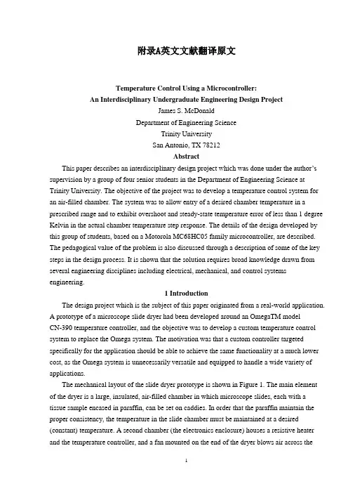
附录A英文文献翻译原文Temperature Control Using a Microcontroller:An Interdisciplinary Undergraduate Engineering Design ProjectJames S. McDonaldDepartment of Engineering ScienceTrinity UniversitySan Antonio, TX 78212AbstractThis paper describes an interdisc iplinary design project which was done under the author’s supervision by a group of four senior students in the Department of Engineering Science at Trinity University. The objective of the project was to develop a temperature control system for an air-filled chamber. The system was to allow entry of a desired chamber temperature in a prescribed range and to exhibit overshoot and steady-state temperature error of less than 1 degree Kelvin in the actual chamber temperature step response. The details of the design developed by this group of students, based on a Motorola MC68HC05 family microcontroller, are described. The pedagogical value of the problem is also discussed through a description of some of the key steps in the design process. It is shown that the solution requires broad knowledge drawn from several engineering disciplines including electrical, mechanical, and control systems engineering.1 IntroductionThe design project which is the subject of this paper originated from a real-world application.A prototype of a microscope slide dryer had been developed around an OmegaTM modelCN-390 temperature controller, and the objective was to develop a custom temperature control system to replace the Omega system. The motivation was that a custom controller targeted specifically for the application should be able to achieve the same functionality at a much lower cost, as the Omega system is unnecessarily versatile and equipped to handle a wide variety of applications.The mechanical layout of the slide dryer prototype is shown in Figure 1. The main element of the dryer is a large, insulated, air-filled chamber in which microscope slides, each with a tissue sample encased in paraffin, can be set on caddies. In order that the paraffin maintain the proper consistency, the temperature in the slide chamber must be maintained at a desired (constant) temperature. A second chamber (the electronics enclosure) houses a resistive heater and the temperature controller, and a fan mounted on the end of the dryer blows air across theheater, carrying heat into the slide chamber. This design project was carried out during academic year 1996–97 by four students under the author’s supervision as a Senior Design project in the Department of Engineering Science at Trinity University. The purpose of this paper isto describe the problem and the students’ solution in some detail, and to discuss some of the pedagogical opportunities offered by an interdisciplinary design project of this type. The students’ own report was presented a t the 1997 National Conference on Undergraduate Research [1]. Section 2 gives a more detailed statement of the problem, including performance specifications, and Section 3 describes the students’ design. Section 4 makes up the bulk of the paper, and discusses in some detail several aspects of the design process which offer unique pedagogical opportunities. Finally, Section 5 offers some conclusions.2 Problem StatementThe basic idea of the project is to replace the relevant parts of the functionality of an Omega CN-390 temperature controller using a custom-designed system. The application dictates that temperature settings are usually kept constant for long periods of time, but it’s nonetheless important that step changes be tracked in a “reasonable” manner. Thus the main requirements boil down to·allowing a chamber temperature set-point to be entered,·displaying both set-point and actual temperatures, and·tracking step changes in set-point temperature with acceptable rise time, steady-state error, and overshoot.Although not explicitly a part of the specifications in Table 1, it was clear that the customer desired digital displays of set-point and actual temperatures, and that set-point temperature entry should be digital as well (as opposed to, say, through a potentiometer setting).3 System DesignThe requirements for digital temperature displays and setpoint entry alone are enough to dictate that a microcontrollerbased design is likely the most appropriate. Figure 2 shows a block diagram of the stude nts’ design.The microcontroller, a MotorolaMC68HC705B16 (6805 for short), is the heart of the system. It accepts inputs from a simple four-key keypad which allow specification of the set-point temperature, and it displays both set-point and measured chamber temperatures using two-digit seven-segment LED displays controlled by a display driver. All these inputs and outputs are accommodated by parallel ports on the 6805. Chamber temperature is sensed using apre-calibrated thermistor and input via one of the 6805’s analog-to-digital inputs. Finally, a pulse-width modulation (PWM) output on the 6805 is used to drive a relay which switches line power to the resistive heater off and on.Figure 3 shows a more detailed schematic of the electronics and their interfacing to the 6805. The keypad, a Storm 3K041103, has four keys which are interfaced to pins PA0{ PA3 of Port A, configured as inputs. One key functions as a mode switch. Two modes are supported: set mode and run mode. In set mode two of the other keys are used to specify the set-point temperature: one increments it and one decrements. The fourth key is unused at present. The LED displays are driven by a Harris Semiconductor ICM7212 display driver interfaced to pins PB0{PB6 of Port B, configured as outputs. The temperature-sensing thermistor drives, through a voltage divider, pin AN0 (one of eight analog inputs). Finally, pin PLMA (one of two PWM outputs) drives the heater relay.Software on the 6805 implements the temperature control algorithm, maintains the temperature displays, and alters the set-point in response to keypad inputs. Because it is not complete at this writing, software will not be discussed in detail in this paper. The control algorithm in particular has not been determined, but it is likely to be a simple proportional controller and certainly not more complex than a PID. Some control design issues will be discussed in Section 4, however.4 The Design ProcessAlthough essentially the project is just to build a thermostat, it presents many nice pedagogical opportunities. The knowledge and experience base of a senior engineering undergraduate are just enough to bring him or her to the brink of a solution to various aspects of the problem. Yet, in each case, realworld considerations complicate the situation significantly.Fortunately these complications are not insurmountable, and the result is a very beneficial design experience. The remainder of this section looks at a few aspects of the problem which present the type of learning opportunity just described. Section 4.1 discusses some of the features of a simplified mathematical model of the thermal properties of the system and how it can beeasily validated experimentally. Section 4.2 describes how realistic control algorithm designs can be arrived at using introductory concepts in control design. Section 4.3 points out some important deficiencies of such a simplified modeling/control design process and how they can be overcome through simulation. Finally, Section 4.4 gives an overview of some of the microcontroller-related design issues which arise and learning opportunities offered.4.1 MathematicalModelLumped-element thermal systems are described in almost any introductory linear control systems text, and just this sort of model is applicable to the slide dryer problem. Figure 4 shows a second-order lumped-element thermal model of the slide dryer. The state variables are the temperatures Ta of the air in the box and Tb of the box itself. The inputs to the system are the power output q(t) of the heater and the ambient temperature T¥. ma and mb are the masses of the air and the box, respectively, and Ca and Cb their specific heats. μ1 and μ2 are heat transfer coefficients from the air to the box and from the box to the external world, respectively.It’s not hard to show that the (linearized) state equationscorresponding to Figure 4 areTaking Laplace transforms of (1) and (2) and solving for Ta(s), which is the output of interest, gives the following open-loop model of the thermal system:where K is a constant and D(s) is a second-order polynomial.K, tz, and the coefficients ofD(s) are functions of the variousparameters appearing in (1) and (2).Of course the various parameters in (1) and (2) are completely unknown, but it’s not hard to show that, regardless of their values, D(s) has two real zeros. Therefore the main transfer function of interest (which isthe one from Q(s), since we’ll assume constant ambient temperature) can be writtenMoreover, it’s not too hard to show that 1=tp1 <1=tz <1=tp2, i.e., that the zero lies between the two poles. Both of these are excellent exercises for the student, and the result is the openloop pole-zero diagram of Figure 5.Obtaining a complete thermal model, then, is reduced to identifying the constant K and the three unknown time constants in (3). Four unknown parameters is quite a few, but simple experiments show that 1=tp1 _ 1=tz;1=tp2 so that tz;tp2 _ 0 are good approximations. Thus the open-loop system is essentially first-order and can therefore be written(where the subscript p1 has been dropped).Simple open-loop step response experiments show that,for a wide range of initial temperatures and heat inputs, K _0:14 _=W and t _ 295 s.14.2 Control System DesignUsing the first-order model of (4) for the open-loop transfer function Gaq(s) and assuming for the moment that linear control of the heater power output q(t) is possible, the block diagram of Figure 6 represents the closed-loop system. Td(s) is the desired, or set-point, temperature,C(s) is the compensator transfer function, and Q(s) is the heater output in watts.Given this simple situation, introductory linear control design tools such as the root locus method can be used to arrive at a C(s) which meets the step response requirements on rise time, steady-state error, and overshoot specified in Table 1. The upshot, of course, is that a proportional controller with sufficient gain can meet all specifications. Overshoot is impossible, and increasing gains decreases both steady-state error and rise time.Unfortunately, sufficient gain to meet the specifications may require larger heat outputs than the heater is capable of producing. This was indeed the case for this system, and the result is that the rise time specification cannot be met. It is quite revealing to the student how useful such an oversimplified model, carefully arrived at, can be in determining overall performance limitations.4.3 Simulation ModelGross performance and its limitations can be determined using the simplified model of Figure 6, but there are a number of other aspects of the closed-loop system whose effects on performance are not so simply modeled. Chief among these are·quantization error in analog-to-digital conversion of the measured temperature and· the use of PWM to control the heater.Both of these are nonlinear and time-varying effects, and the only practical way to study them is through simulation (or experiment, of course).Figure 7 shows a SimulinkTM block diagram of the closed-loop system which incorporates these effects. A/D converter quantization and saturation are modeled using standard Simulink quantizer and saturation blocks. Modeling PWM is more complicated and requires a customS-function to represent it.This simulation model has proven particularly useful in gauging the effects of varying thebasic PWM parameters and hence selecting them appropriately. (I.e., the longer the period, the larger the temperature error PWM introduces. On the other hand, a long period is desirable to avoid excessiv e relay “chatter,” among other things.) PWM is often difficult for students to grasp, and the simulation model allows an exploration of its operation and effects which is quite revealing.4.4 The MicrocontrollerSimple closed-loop control, keypad reading, and display control are some of the classic applications of microcontrollers, and this project incorporates all three. It is therefore an excellent all-around exercise in microcontroller applications. In addition, because the project isto produce an actua l packaged prototype, it won’t do to use a simple evaluation board with theI/O pins jumpered to the target system. Instead, it’s necessary to develop a complete embedded application. This entails the choice of an appropriate part from the broad range offered in a typical microcontroller family and learning to use a fairly sophisticated development environment. Finally, a custom printed-circuit board for the microcontroller and peripherals must be designed and fabricated.Microcontroller Selection. In view of existing local expertise, the Motorola line of microcontrollers was chosen for this project. Still, this does not narrow the choice down much. A fairly disciplined study of system requirements is necessary to specify which microcontroller, out of scores of variants, is required for the job. This is difficult for students, as they generally lack the experience and intuition needed as well as the perseverance to wade through manufacturers’ selection guides.Part of the problem is in choosing methods for interfacing the various peripherals (e.g., what kind of display driver should be used?). A study of relevant Motorola application notes [2, 3, 4] proved very helpful in understandingwhat basic approaches are available, and what microcontroller/peripheral combinations should be considered.The MC68HC705B16 was finally chosen on the basis of its availableA/D inputs and PWMoutputs as well as 24 digital I/O lines. In retrospect this is probably overkill, as only oneA/D channel, one PWM channel, and 11 I/O pins are actually required (see Figure 3). The decision was made to err on the safe side because a complete development system specific to the chosen part was necessary, and the project budget did not permit a second such system to be purchased should the firstprove inadequate.Microcontroller Application Development. Breadboarding of the peripheral hardware, development of microcontroller software, and final debugging and testing of a customprinted-circuit board for the microcontroller and peripherals all require a development environment of some kind. The choice of a development environment, like that of themicrocontroller itself, can be bewildering and requires some faculty expertise. Motorola makes three grades of development environment ranging from simple evaluation boards (at around $100) to full-blown real-time in-circuit emulators (at more like $7500). The middle option was chosen for this project: the MMEVS, which consists of _ a platform board (which supports all 6805-family parts), _ an emulator module (specific to B-series parts), and _ a cable and target head adapter (package-specific). Overall, the system costs about $900 and provides, with some limitations, in-circuit emulation capability. It also comes with the simple but sufficient software development environment RAPID [5].Students find learning to use this type of system challenging, but the experience they gain in real-world microcontroller application development greatly exceeds the typical first-course experience using simple evaluation boards.Printed-Circuit Board. The layout of a simple (though definitely not trivial) printed-circuit board is another practical learning opportunity presented by this project. The final board layout, with package outlines, is shown (at 50% of actual size) in Figure 8. The relative simplicity of the circuit makes manual placement and routing practical—in fact, it likely gives better results than automatic in an application like this—and the student is therefore exposed to fundamental issues of printed-circuit layout and basic design rules. The layout software used was the very nice package pcb,2 and the board was fabricated in-house with the aid of our staff electronics technician.5 ConclusionThe aim of this paper has been to describe an interdisciplinary, undergraduate engineering design project: a microcontroller- based temperature control system with digital set-point entry and set-point/actual temperature display. A particular design of such a system has been described, and a number of design issues which arise—from a variety of engineering disciplines—have been discussed. Resolution of these issues generally requires knowledge beyond that acquired in introductory courses, but realistically accessible to advance undergraduate students, especiallywith the advice and supervision of faculty.Desirable features of the problem, from a pedagogical viewpoint, include the use of a microcontroller with simple peripherals, the opportunity to usefully apply introductorylevel modeling of physical systems and design of closed-loop controls, and the need for relatively simple experimentation (for model validation) and simulation (for detailed performance prediction). Also desirable are some of the technologyrelated aspects of the problem including practical use of resistive heaters and temperature sensors (requiring knowledge of PWM and calibration techniques, respectively), microcontroller selection and use of development systems, and printedcircuit design.AcknowledgementsThe author would like to acknowledge the hard work, dedication, and ability shown by the students involved in this project: Mark Langsdorf, Matt Rall, PamRinehart, and David Schuchmann. It is their project, and credit for its success belongs to them.References[1] M. Langsdorf, M. Rall, D. Schuchmann, and P. Rinehart,“Temperature control of a microscope slide dryer,” in1997 National Conference on Undergraduate Research,(Austin, TX), April 1997. Poster presentation.[2] Motorola, Inc., Phoenix, AZ, Temperature Measurementand Display Using the MC68HC05B4 and the MC14489,1990. Motorola SemiconductorApplicationNote AN431.[3] Motorola, Inc., Phoenix, AZ, HC05 MCU LED DriveTechniques Using the MC68HC705J1A, 1995. MotorolaSemiconductor Application Note AN1238.[4] Motorola, Inc., Phoenix, AZ, HC05MCU Keypad DecodingTechniques Using the MC68HC705J1A, 1995. MotorolaSemiconductor Application Note AN1239.[5] Motorola, Inc., Phoenix, AZ, RAPID Integrated DevelopmentEnvironment User’s Manual, 1993. (RAPID wasdeveloped by P & E Microcomputer Systems, Inc.).附录B英文文献翻译中文单片机温度控制:一个跨学科的本科生工程设计项目JamesS.McDonald工程科学系三一大学德克萨斯州圣安东尼奥市78212摘要本文所描述的是作者领导由四个三一大学高年级学生组成的团队进行的一个跨学科工程项目的设计。
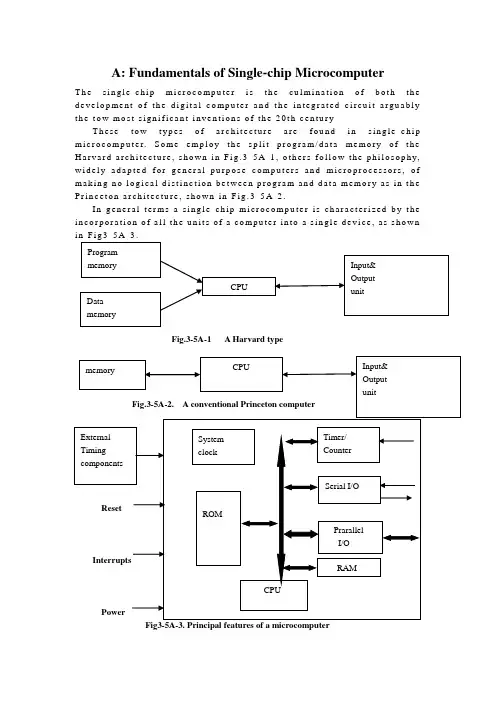
A: Fundamentals of Single-chip MicrocomputerT h e s i n g l e-c h i p m i c r o c o mp u t e r i s t h e c u l m i n a t i o n o f b o t h t h e d e v e l o p me n t o f t h e d i g i t a l c o mp u t e r a n d t h e i n t e g r a t e d c i r c u i t a r g u a b l y t h e t o w m o s t s i g n i f i c a n t i n v e n t i o n s o f t h e20t h c e n t u r yT h e s e t o w t y p e s o f a r c h i t e c t u r e a r e f o u n d i n s i n g l e-c h i p m i c r o c o m p u t e r.S o me e m p l o y t h e s p l i t p r o g r a m/d a t a m e mo r y o f t h e H a r v a r d a r c h i t e c t u r e,s h o w n i n F i g.3-5A-1,o t h e r s f o l l o w t h e p h i l o s o p h y, w i d e l y a d a p t e d f o r g e n e r a l-p u r p o s e c o mp u t e r s a n d m i c r o p r o c e s s o r s,o f m a k i n g n o l o g i c a l d i s t i n c t i o n b e t w e e n p r o g r a m a n d d a t a m e mo r y a s i n t h e P r i n c e t o n a r c h i t e c t u r e,s h o w n i n F i g.3-5A-2.I n g e n e r a l t e r m s a s i n g l e-c h i p m i c r o c o m p u t e r i s c h a r a c t e r i z e d b y t h e i n c o r p o r a t i o n o f a l l t h e u n i t s o f a c o m p u t e r i n t o a s i n g l e d e v i c e, a s s h o w n iFig.3-5A-1 A Harvard typeFig3-5A-3. Principal features of a microcomputerRead only memory (ROM)R O M i s u s u a l l y f o r t h e p e r m a n e n t, n o n-v o l a t i l e s t o r a g e o f a n a p p l i c a t i o n s p r o g r a m.M a n y m i c r o c o m p u t e r s a n d m i c r o c o n t r o l l e r s a r e i n t e n d e d f o r h i g h-v o l u m e a p p l i c a t i o n s a n d h e n c e t h e e c o n o m i c a l m a n u f a c t u r e o f t h e d e v i c e s r e q u i r e s t h a t t h e c o n t e n t s o f t h e p r o g r a m m e m o r y b e c o m m i t t e d p e r m a n e n t l y d u r i n g t h e m a n u f a c t u r e o f c h i p s.C l e a r l y,t h i s i m p l i e s a r i g o r o u s a p p r o a c h t o R O M c o d e d e v e l o p m e n t s i n c e c h a n g e s c a n n o t b e m a d e a f t e r m a n u f a c t u r e .T h i s d e v e l o p m e n t p r o c e s s m a y i n v o l v e e m u l a t i o n u s i n g a s o p h i s t i c a t e d d e v e l o p m e n t s y s t e m w i t h a h a r d w a r e e m u l a t i o n c a p a b i l i t y a s w e l l a s t h e u s e o f p o w e r f u l s o f t w a r e t o o l s.S o m e m a n u f a c t u r e r s p r o v i d e a d d i t i o n a l R O M o p t i o n s b y i n c l u d i n g i n t h e i r r a n g e d e v i c e s w i t h(o r i n t e n d e d f o r u s e w i t h)u s e r p r o g r a m m a b l e m e m o r y.T h e s i m p l e s t o f t h e s e i s u s u a l l y d e v i c e w h i c h c a n o p e r a t e i n a m i c r o p r o c e s s o r m o d e b y u s i n g s o m e o f t h e i n p u t/o u t p u t l i n e s a s a n a d d r e s s a n d d a t a b u s f o r a c c e s s i n g e x t e r n a l m e m o r y.T h i s t y p e o f d e v i c ec a n b e h a v e f u n c t i o n a l l y a s t h e s i n g l e c h i p m i c r o c o m p u t e r f r o m w h i c h i t i sd e r i v e d a l b e i t w i t h r e s t r i c t e d I/O a n d a mo d i f i e d e x t e r n a l c i r c u i t. T h e u s e o f t h e s e R O M l e s s d e v i c e s i s c o m m o n e v e n i n p r o d u c t i o n c i r c u i t s w h e r e t h e v o l u m e d o e s n o t j u s t i f y t h e d e v e l o p m e n t c o s t s o f c u s t o m o n-c h i p R O M[2];t h e r e c a n s t i l l b e a s i g n i f i c a n t s a v i n g i n I/O a n d o t h e r c h i p s c o mp a r e d t o a c o n v e n t i o n a l m i c r o p r o c e s s o r b a s e d c i r c u i t.M o r e e x a c t r e p l a c e m e n t f o r R O M d e v i c e s c a n b e o b t a i n e d i n t h e f o r m o f v a r i a n t s w i t h 'p i g g y-b a c k'E P R O M(E r a s a b l e p r o g r a m m a b l e R O M)s o c k e t s o r d e v i c e s w i t h E P R O M i n s t e a d o f R O M。
SCM is an integrated circuit chip,is the use of large scale integrated circuit technology to a data processing capability of CPU CPU random access memory RAM,read-only memory ROM,a variety of I / O port and interrupt system, timers / timer functions (which may also include display driver circuitry,pulse width modulation circuit,analog multiplexer,A / D converter circuit)integrated into a silicon constitute a small and complete computer systems.SCM is also known as micro—controller (Microcontroller), because it is the first to be used in industrial control。
Only a single chip by the CPU chip developed from a dedicated processor。
The first design is by a large number of peripherals and CPU on a chip in the computer system, smaller, more easily integrated into a complex and demanding on the volume control device which。
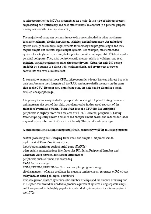
A microcontroller (or MCU) is a computer-on-a-chip. It is a type of microprocessor emphasizing self-sufficiency and cost-effectiveness, in contrast to a general-purpose microprocessor (the kind used in a PC).The majority of computer systems in use today are embedded in other machinery, such as telephones, clocks, appliances, vehicles, and infrastructure. An embedded system usually has minimal requirements for memory and program length and may require simple but unusual input/output systems. For example, most embedded systems lack keyboards, screens, disks, printers, or other recognizable I/O devices of a personal computer. They may control electric motors, relays or voltages, and read switches, variable resistors or other electronic devices. Often, the only I/O device readable by a human is a single light-emitting diode, and severe cost or power constraints can even eliminate that.In contrast to general-purpose CPUs, microcontrollers do not have an address bus or a data bus, because they integrate all the RAM and non-volatile memory on the same chip as the CPU. Because they need fewer pins, the chip can be placed in a much smaller, cheaper package.Integrating the memory and other peripherals on a single chip and testing them as a unit increases the cost of that chip, but often results in decreased net cost of the embedded system as a whole. (Even if the cost of a CPU that has integrated peripherals is slightly more than the cost of a CPU + external peripherals, having fewer chips typically allows a smaller and cheaper circuit board, and reduces the labor required to assemble and test the circuit board). This trend leads to design.A microcontroller is a single integrated circuit, commonly with the following features:central processing unit - ranging from small and simple 4-bit processors to sophisticated 32- or 64-bit processorsinput/output interfaces such as serial ports (UARTs)other serial communications interfaces like I²C, Serial Peripheral Interface and Controller Area Network for system interconnectperipherals such as timers and watchdogRAM for data storageROM, EPROM, EEPROM or Flash memory for program storageclock generator - often an oscillator for a quartz timing crystal, resonator or RC circuit many include analog-to-digital convertersThis integration drastically reduces the number of chips and the amount of wiring and PCB space that would be needed to produce equivalent systems using separate chips and have proved to be highly popular in embedded systems since their introduction in the 1970s.Some microcontrollers can afford to use a Harvard architecture: separate memory buses for instructions and data, allowing accesses to take place concurrently.The decision of which peripheral to integrate is often difficult. The Microcontroller vendors often trade operating frequencies and system design flexibility againsttime-to-market requirements from their customers and overall lower system cost. Manufacturers have to balance the need to minimize the chip size against additional functionality.Microcontroller architectures are available from many different vendors in so many varieties that each instruction set architecture could rightly belong to a category of their own. Chief among these are the 8051, Z80 and ARM derivatives.[citation needed]单片机即单片微型计算机,是把中央处理器、存储器、定时/计数器、输入输出接口都集成在一块集成电路芯片上的微型计算机。
单片机外文翻译外文文献英文文献单片机的发展与应用THE Application and Development ofMicrocontroller UnitMonolithic integrated circuits are a computer chip. It uses tec hnology will have a data processing ability of the microprocessor (cpu), storage in rom (program memory and data storage ram ), the input, output interfaces circuit (I/O) integration interface i tu rned around with a chip in that small, constitutes a very good and the computer hardware system, where the application under the c ontrol of a monolithic integrated circuits can be accurate, fast and efficient procedures provided in advance to complete the task. So, a monolithic integrated circuits will have a computer chip of all t he functions.Thus, the microprocessor (monolithic integrated circuits has generally cpu )chips are not functional, it can independently com plete modern industrial control required for intelligent control func tions, it is monolithic integrated circuits of the biggest characteristi c.Monolithic integrated circuits, however, and different from mac hines ( a microprocessor chips, the memory chip and input and o utput interfaces chip in with a piece of printed circuit board of a microcomputer ), Monolithic integrated circuits chip in developing ago, it is only a function vlsi will have a strong, If of application development, it is a small microcomputer control system, but it m achine or a personal computer (pc is essential. the difference betw een).Monolithic integrated circuits of the application of chips at the level of application, the user (monolithic integrated circuits lear ners with users understand the structure of the chip )monolithic integrated circuits and instruction system, and the integrated use o f technology and system design to the theory and techniques, in th is particular chip design application, thereby, the chip with a parti cular function.Different monolithic integrated circuits have different hardware and software, or the technical features are different, Character de pends on a hardware chip monolithic integrated circuits the intern al structure of the user to use some monolithic integrated circuits, we must know this type of product whether to meet the needs of the facilities and application of the indicators required. The tech nical features include functional characteristics, control and electric al attributes, These information to manufacturers in the technical manual. Software features refers to an instruction system and devel opment support of the environment, the quality of instruction or monolithic integrated circuits for reference, data processing and log ical processing, output characteristics and to the power input requi rements, etc. Development support of the environment, including th e instructions of compatible and portable. support software (contai ns can support the development and application software and hard ware resources. resources). To take advantage of the model of deve lopment of a monolithic integrated circuits application systems, lea rn its structural features and technological characteristic is require d.Monolithic integrated circuits to control system will ever use o f sophisticated electronic circuit or circuit, a control system to achi eve the software controls and enable intelligent, It is monolithic in tegrated circuits to control areas, such as communications products and household appliances, the instruments and processes to contr ol and control devices, theapplication of more monolithic integrate d circuits sector.Monolithic integrated circuits, of course, the application is not limited to the application or the category of the economic perfor mance is more important it is a fundamental change in the traditi onal methods designed to control and mind control techniques. it i s a revolution is an important milestone.Can say now is the policy, a hundred schools of thought conte nd "monolithic integrated circuits, World chip all the company unv eiled his monolithic integrated circuits, from 8, 16 to 32 bits, and,with mainstream c51 series of, and there is not compatible with e ach other, but they, as complementary to monolithic integrated circ uits, the application of the world provide a broad.Throughout monolithic integrated circuits of the development p rocess, the trend of a monolithic integrated circuits, has :1.the low TDP COMSMcs -51 8031 a series of TDP for 630mw, and now a monolit hic integrated circuits, and generally in 100mw. As to ask for lowe r TDP monolithic integrated circuits, and now each monolithic inte grated circuits are used in the basic cmos (complementary metal o xides semiconductor technology). Like 80c51 adopt a hmos (the hig h density metal oxides semiconductor technology) and chmos (com plementary high density metal oxides semiconductor technology). C mos although TDP low, but owing to their physical characteristics to their work at a speed isn't high enough, but it has a high-spee d chmos TDP and low, these features are more appropriate to ask for lower TDP in a battery operated applications. so this process will be for a period of development. the main way to monolithic i ntegrated circuits。
Progress in ComputersPrestige Lecture delivered to IEE, Cambridge, on 5 February 2004Maurice WilkesComputer LaboratoryUniversity of CambridgeThe first stored program computers began to work around 1950. The one we built in Cambridge, the EDSAC was first used in the summer of 1949.These early experimental computers were built by people like myself with varying backgrounds. We all had extensive experience in electronic engineering and were confident that that experience would stand us in good stead. This proved true, although we had some new things to learn. The most important of these was that transients must be treated correctly; what would cause a harmless flash on the screen of a television set could lead to a serious error in a computer.As far as computing circuits were concerned, we found ourselves with an embarass de richess. For example, we could use vacuum tube diodes for gates as we did in the EDSAC or pentodes with control signals on both grids, a system widely used elsewhere. This sort of choice persisted and the term families of logic came into use. Those who have worked in the computer field will remember TTL, ECL and CMOS. Of these, CMOS has now become dominant.In those early years, the IEE was still dominated by power engineering and w e had to fight a number of major battles in order to get radio engineering along with the rapidly developing subject of electronics.dubbed in the IEE light current electrical engineering.properly recognised as an activity in its own right. I remember that we had some difficulty in organising a conference because the power engineers’ ways of doing things were not our ways. A minor source of irritation was that all IEE published papers were expected to start with a lengthy statement of earlier practice, something difficult to do when there was no earlier practiceConsolidation in the 1960sBy the late 50s or early 1960s, the heroic pioneering stage was over and the computer field was starting up in real earnest. The number of computers in the world had increased and they were much more reliable than the very early ones . To those years we can ascribe the first steps in high level languages and the first operating systems. Experimental time-sharing was beginning, and ultimately computer graphics was to come along.Above all, transistors began to replace vacuum tubes. This change presented a formidable challenge to the engineers of the day. They had to forget what they knew about circuits and start again. It can only be said that they measured up superbly well to the challenge and that the change could not have gone more smoothly.Soon it was found possible to put more than one transistor on the same bit of silicon, and this was the beginning of integrated circuits. As time went on, a sufficient level ofintegration was reached for one chip to accommodate enough transistors for a small number of gates or flip flops. This led to a range of chips known as the 7400 series. The gates and flip flops were independent of one another and each had its own pins. They could be connected by off-chip wiring to make a computer or anything else.These chips made a new kind of computer possible. It was called a minicomputer. It was something less that a mainframe, but still very powerful, and much more affordable. Instead of having one expensive mainframe for the whole organisation, a business or a university was able to have a minicomputer for each major department.Before long minicomputers began to spread and become more powerful. The world was hungry for computing power and it had been very frustrating for industry not to be able to supply it on the scale required and at a reasonable cost. Minicomputers transformed the situation.The fall in the cost of computing did not start with the minicomputer; it had always been that way. This was what I meant when I referred in my abstract to inflation in the computer industry ‘going the other way’. As time goes on people get more for their money, not less.Research in Computer Hardware.The time that I am describing was a wonderful one for research in computer hardware. The user of the 7400 series could work at the gate and flip-flop level and yet the overall level of integration was sufficient to give a degree of reliability far above that of discreet transistors. The researcher, in a university or elsewhere, could build any digital device that a fertile imagination could conjure up. In the Computer Laboratory we built the Cambridge CAP, a full-scale minicomputer with fancy capability logic.The 7400 series was still going strong in the mid 1970s and was used for the Cambridge Ring, a pioneering wide-band local area network. Publication of the design study for the Ring came just before the announcement of the Ethernet. Until these two systems appeared, users had mostly been content with teletype-based local area networks.Rings need high reliability because, as the pulses go repeatedly round the ring, they must be continually amplified and regenerated. It was the high reliability provided by the 7400 series of chips that gave us the courage needed to embark on the project for the Cambridge Ring.The RISC Movement and Its AftermathEarly computers had simple instruction sets. As time went on designers of commercially available machines added additional features which they thought would improve performance. Few comparative measurements were done and on the whole the choice of features depended upon the designer’s intuition.In 1980, the RISC movement that was to change all this broke on the world. The movement opened with a paper by Patterson and Ditzel entitled The Case for the Reduced Instructions Set Computer.Apart from leading to a striking acronym, this title conveys little of the insights into instruction set design which went with the RISC movement, in particular the way it facilitated pipelining, a system whereby several instructions may be in different stages of execution within the processor at the same time. Pipelining was not new, but it was new for small computersThe RISC movement benefited greatly from methods which had rec ently become available for estimating the performance to be expected from a computer design without actually implementing it. I refer to the use of a powerful existing computer to simulate the new design. By the use of simulation, RISC advocates were able to predict with some confidence that a good RISC design would be able to out-perform the best conventionalcomputers using the same circuit technology. This prediction was ultimately born out in practice.Simulation made rapid progress and soon came into universal use by computer designers. In consequence, computer design has become more of a science and less of an art. Today, designers expect to have a roomful of, computers available to do their simulations, not just one. They refer to such a roomful by the attractive name of computer farm.The x86 Instruction SetLittle is now heard of pre-RISC instruction sets with one major exception, namely that of the Intel 8086 and its progeny, collectively referred to as x86. This has become the dominant instruction set and the RISC instruction sets that originally had a considerable measure of success are having to put up a hard fight for survival.This dominance of x86 disappoints people like myself who come from the research wings.both academic and industrial.of the computer field. No doubt, business considerations have a lot to do with the survival of x86, but there are other reasons as well. However much we research oriented people would like to think otherwise. high level languages have not yet eliminated the use of machine code altogether. We need to keep reminding ourselves that there is much to be said for strict binary compatibility with previous usage when that can be attained. Nevertheless, things might have been different if Intel’s major attempt to produ ce a good RISC chip had been more successful. I am referring to the i860 (not the i960, which was something different). In many ways the i860 was an excellent chip, but its software interface did not fit it to be used in a workstation.There is an interesting sting in the tail of this apparently easy triumph of the x86 instruction set. It proved impossible to match the steadily increasing speed of RISC processors by direct implementation of the x86 instruction set as had been done in the past. Instead, designers took a leaf out of the RISC book; although it is not obvious, on the surface, a modern x86 processor chip contains hidden within it a RISC-style processor with its own internal RISC coding. The incoming x86 code is, after suitable massaging, converted into this internal code and handed over to the RISC processor where the critical execution is performed.In this summing up of the RISC movement, I rely heavily on the latest edition of Hennessy and Patterson’s books on computer design as my supporting authority; see in particular Computer Architecture, third edition, 2003, pp 146, 151-4, 157-8.The IA-64 instruction set.Some time ago, Intel and Hewlett-Packard introduced the IA-64 instruction set. This was primarily intended to meet a generally recognised need for a 64 bit address space. In this, it followed the lead of the designers of the MIPS R4000 and Alpha. However one would have thought that Intel would have stressed compatibility with the x86; the puzzle is that they did the exact opposite.Moreover, built into the design of IA-64 is a feature known as predication which makes it incompatible in a major way with all other instruction sets. In particular, it needs 6 extra bits with each instruction. This upsets the traditional balance between instruction word length and information content, and it changes significantly the brief of the compiler writer.In spite of having an entirely new instruction set, Intel made the puzzling claim that chips based on IA-64 would be compatible with earlier x86 chips. It was hard to see exactly what was meant.Chips for the latest IA-64 processor, namely, the Itanium, appear to have special hardware for compatibility. Even so, x86 code runs very slowly.Because of the above complications, implementation of IA-64 requires a larger chipthan is required for more conventional instruction sets. This in turn implies a higher cost. Such at any rate, is the received wisdom, and, as a general principle, it was repeated as such by Gordon Moore when he visited Cambridge recently to open the Betty and Gordon Moore Library. I have, however, heard it said that the matter appears differently from within Intel. This I do not understand. But I am very ready to admit that I am completely out of my depth as regards the economics of the semiconductor industry.AMD have defined a 64 bit instruction set that is more compatible with x86 and they appear to be making headway with it. The chip is not a particularly large one. Some people think that this is what Intel should have done. [Since the lecture was delivered, Intel have announced that they will market a range of chips essentially compatible with those offered by AMD.]The Relentless Drive towards Smaller TransistorsThe scale of integration continued to increase. This was achieved by shrinking the original transistors so that more could be put on a chip. Moreover, the laws of physics were on the side of the manufacturers. The transistors also got faster, simply by getting smaller. It was therefore possible to have, at the same time, both high density and high speed.There was a further advantage. Chips are made on discs of silicon, known as wafers. Each wafer has on it a large number of individual chips, which are processed together and later separated. Since shrinkage makes it possible to get more chips on a wafer, the cost per chip goes down.Falling unit cost was important to the industry because, if the latest chips are cheaper to make as well as faster, there is no reason to go on offering the old ones, at least not indefinitely. There can thus be one product for the entire market.However, detailed cost calculations showed that, in order to maintain this advantage as shrinkage proceeded beyond a certain point, it would be necessary to move to larger wafers. The increase in the size of wafers was no small matter. Originally, wafers were one or two inches in diameter, and by 2000 they were as much as twelve inches. At first, it puzzled me that, when shrinkage presented so many other problems, the industry should make things harder for itself by going to larger wafers. I now see that reducing unit cost was just as important to the industry as increasing the number of transistors on a chip, and that this justified the additional investment in foundries and the increased risk.The degree of integration is measured by the feature size, which, for a given technology, is best defined as the half the distance between wires in the densest chips made in that technology. At the present time, production of 90 nm chips is still building up Suspension of LawIn March 1997, Gordon Moore was a guest speaker at the celebrations of the centenary of the discovery of the electron held at the Cavendish Laboratory. It was during the course of his lecture that I first heard the fact that you can have silicon chips that are both fast and low in cost described as a violation of Murphy’s law.or Sod’s law as it is usually called in the UK. Moore said that experience in other fields would lead you to expect to have to choose between speed and cost, or to compromise between them. In fact, in the case of silicon chips, it is possible to have both.In a reference book available on the web, Murphy is identified as an engineer working on human acceleration tests for the US Air Force in 1949. However, we were perfectly familiar with the law in my student days, when we called it by a much more prosaic name than either of those mentioned above, namely, the Law of General Cussedness. We even had a mock examination question in which the law featured. It was the type of question in which the first part asks for a definition of some law or principle and the second part contains aproblem to be solved with the aid of it. In our case the first part was to define the Law of General Cussedness and the second was the problem;A cyclist sets out on a circular cycling tour. Derive an equation giving the direction of the wind at any time.The single-chip computerAt each shrinkage the number of chips was reduced and there were fewer wires going from one chip to another. This led to an additional increment in overall speed, since the transmission of signals from one chip to another takes a long time.Eventually, shrinkage proceeded to the point at which the whole processor except for the caches could be put on one chip. This enabled a workstation to be built that out-performed the fastest minicomputer of the day, and the result was to kill the minicomputer stone dead. As we all know, this had severe consequences for the computer industry and for the people working in it.From the above time the high density CMOS silicon chip was Cock of the Roost. Shrinkage went on until millions of transistors could be put on a single chip and the speed went up in proportion.Processor designers began to experiment with new architectural features designed to give extra speed. One very successful experiment concerned methods for predicting the way program branches would go. It was a surprise to me how successful this was. It led to a significant speeding up of program execution and other forms of prediction followed Equally surprising is what it has been found possible to put on a single chip computer by way of advanced features. For example, features that had been developed for the IBM Model 91.the giant computer at the top of the System 360 range.are now to be found on microcomputersMurphy’s Law remained in a state of suspension. No longer did it make sense to build experimental computers out of chips with a small scale of integration, such as that provided by the 7400 series. People who wanted to do hardware research at the circuit level had no option but to design chips and seek for ways to get them made. For a time, this was possible, if not easyUnfortunately, there has since been a dramatic increase in the cost of making chips, mainly because of the increased cost of making masks for lithography, a photographic process used in the manufacture of chips. It has, in consequence, again become very difficult to finance the making of research chips, and this is a currently cause for some concern.The Semiconductor Road MapThe extensive research and development work underlying the above advances has been made possible by a remarkable cooperative effort on the part of the international semiconductor industry.At one time US monopoly laws would probably have made it illegal for US companies to participate in such an effort. However about 1980 significant and far reaching changes took place in the laws. The concept of pre-competitive research was introduced. Companies can now collaborate at the pre-competitive stage and later go on to develop products of their own in the regular competitive manner.The agent by which the pre-competitive research in the semi-conductor industry is managed is known as the Semiconductor Industry Association (SIA). This has been active as a US organisation since 1992 and it became international in 1998. Membership is open to any organisation that can contribute to the research effort.Every two years SIA produces a new version of a document known as the International Technological Roadmap for Semiconductors (ITRS), with an update in the intermediate years. The first volume bearing the title ‘Roadmap’ was issued in 1994 but two reports, written in1992 and distributed in 1993, are regarded as the true beginning of the series.Successive roadmaps aim at providing the best available industrial consensus on the way that the industry should move forward. They set out in great detail.over a 15 year horizon. the targets that must be achieved if the number of components on a chip is to be doubled every eighteen months.that is, if Moore’s law is to be maintained.-and if the cost per chip is to fall.In the case of some items, the way ahead is clear. In others, manufacturing problems are foreseen and solutions to them are known, although not yet fully worked out; these areas are coloured yellow in the tables. Areas for which problems are foreseen, but for which no manufacturable solutions are known, are coloured red. Red areas are referred to as Red Brick Walls.The targets set out in the Roadmaps have proved realistic as well as challenging, and the progress of the industry as a whole has followed the Roadmaps closely. This is a remarkable achievement and it may be said that the merits of cooperation and competition have been combined in an admirable manner.It is to be noted that the major strategic decisions affecting the progress of the industry have been taken at the pre-competitive level in relative openness, rather than behind closed doors. These include the progression to larger wafers.By 1995, I had begun to wonder exactly what would happen when the inevitable point was reached at which it became impossible to make transistors any smaller. My enquiries led me to visit ARPA headquarters in Washington DC, where I was given a copy of the recently produced Roadmap for 1994. This made it plain that serious problems would arise when a feature size of 100 nm was reached, an event projected to happen in 2007, with 70 nm following in 2010. The year for which the coming of 100 nm (or rather 90 nm) was projected was in later Roadmaps moved forward to 2004 and in the event the industry got there a little sooner.I presented the above information from the 1994 Roadmap, along with such other information that I could obtain, in a lecture to the IEE in London, entitled The CMOS end-point and related topics in Computing and delivered on 8 February 1996.The idea that I then had was that the end would be a direct consequence of the number of electrons available to represent a one being reduced from thousands to a few hundred. At this point statistical fluctuations would become troublesome, and thereafter the circuits would either fail to work, or if they did work would not be any faster. In fact the physical limitations that are now beginning to make themselves felt do not arise through shortage of electrons, but because the insulating layers on the chip have become so thin that leakage due to quantum mechanical tunnelling has become troublesome.There are many problems facing the chip manufacturer other than those that arise from fundamental physics, especially problems with lithography. In an update to the 2001 Roadmap published in 2002, it was stated that the continuation of progress at present rate will be at risk as we approach 2005 when the roadmap projects that progress will stall without research break-throughs in most technical areas “. This was the most specific statement about the Red Brick Wall, that had so far come from the SIA and it was a strong one. The 2003 Roadmap reinforces this statement by showing many areas marked red, indicating the existence of problems for which no manufacturable solutions are known.It is satisfactory to report that, so far, timely solutions have been found to all the problems encountered. The Roadmap is a remarkable document and, for all its frankness about the problems looming above, it radiates immense confidence. Prevailing opinion reflects that confidence and there is a general expectation that, by one means or another,shrinkage will continue, perhaps down to 45 nm or even less.However, costs will rise steeply and at an increasing rate. It is cost that will ultimately be seen as the reason for calling a halt. The exact point at which an industrial consensus is reached that the escalating costs can no longer be met will depend on the general economic climate as well as on the financial strength of the semiconductor industry itself.。
关于单片机的英文文献engine-control systems, brakingsystems (ABS). applications thatbenefitThe General Situation of AT89C51Microcontrollers are used in a multitude of commercial applicationssuch as modems, motor-control systems, air conditioner control systems, automotive engine and amongothers. The high processing speed and enhanced peripheral set of these microcontrollers make them suitable for such high-speed event-based applications. However, these critical application domains also require that these microcontrollers are highly reliable. The highreliability and low market risks can be ensured by a robust testing process and a proper tools environment for the validation of these microcontrollers both at the component and at the system level. Intel Platform Engineering department developed an object-oriented multi-threaded test environment for the validation of its AT89C51 automotive microcontrollers. The goals of this environment was not only to provide a robust testing environment for theAT89C51 automotive microcontrollers, but to develop an environment which canbe easilyextended and reused for the validation of several other futuremicrocontrollers. The environment was developed in conjunction withMicrosoft Foundation Classes (AT89C51). The paper describes the design and mechanism of this test environment, its interactions with varioushardware/software environmental components, and how to use AT89C51.1.1 IntroductionThe 8-bit AT89C51 CHMOSmicrocontrollers are designed to handle high-speed calculations and fast input/output operations. MCS 51microcontrollers are typically used for high-speed event control systems. Commercial applications include modems,motor-control systems, printers, photocopiers, air conditioner control systems, disk drives, and medical instruments. The automotive industry use MCS 51 microcontrollers in airbags, suspension systems, and antilock The AT89C51 is especially well suited to from itsprocessing speed and enhanced on-chip dynamicsuspension, antilock braking, and stability control applications.peripheral functions set, such as automotive power-train control, vehicleBecause of these critical applications, the market requires a reliable cost-effective controller with a low interrupt latency response, abilityto service the high number of time and event driven integrated peripherals needed in real time applications, and a CPUwith above average processing power in a single package. The financial and legal risk of having devices that operate unpredictably is very high. Once in the market, particularly in mission critical applications such as an autopilot or anti-lockbraking system, mistakes are financially prohibitive. Redesign costs can run as high as a $500K, much more if the fix means 2 back annotating it across a product family that share the samecore and/or peripheral design flaw. In addition, field replacements of components is extremely expensive, as the devices are typically sealed in modules with a total value several times that of the component. To mitigate these problems, it is essential that comprehensive testing of the controllers be carried out at both the component level and system level under worst case environmental and voltage conditions. This complete and thorough validation necessitates not only a well-defined process but also a proper environment and tools to facilitate and execute the mission successfully. Intel Chandler Platform Engineering group provides post silicon system validation (SV)of various micro-controllers and processors. The system validation process can be broken into three major parts. The type of the device and its application requirements determine which types of testing are performed on the device.1.2 The AT89C51 provides the following standard features:4Kbytes of Flash, 128 bytes of RAM, 32 I/O lines, two 16-bittimer/counters, a five vector two-level interrupt architecture, a full duple serial port, on-chip oscillator and clock circuitry. In addition, the AT89C51 is designed with static logic for operation down to zero frequency and supports two software selectable power saving modes. The Idle Modestops the CPUwhile allowing the RAM,timer/counters, serial port and interrupt sys -tem to continue functioning. The Power-down Mode saves the。
我国的单片机起步虽然较晚,但经过几十年的发展,也取得了巨大的成就。
不论是工业生产还是社会生活的各个方面都离不开单片机的使用。
下面是搜素整理的单片机英文参考文献的分享,以供参考。
单片机英文参考文献一: [1]Hui Wang. Optimal Design of Single Chip Microcomputer Multi-machine Serial Communication based on Signal VerificationTechnology[J]. International Journal of Intelligent Information and Management Science,2020,9(1)。
[2]Philip J. Basford,Steven J. Johnston,Colin S. Perkins,Tony Garnock-Jones,Fung Po Tso,Dimitrios Pezaros,Robert D. Mullins,Eiko Yoneki,Jeremy Singer,Simon J. Cox. Performance analysis of single board computer clusters[J]. Future Generation ComputerSystems,2020,102. [3]. Computers; Reports from University of Southampton Describe Recent Advances in Computers (Performance Analysis of Single Board Computer Clusters)[J]. Computers, Networks & Communications,2020. [4]Yunyu Cao,Jinjin Dang,Chenxu Cao. Design of Automobile Digital Tire Pressure Detector[J]. Journal of Scientific Research and Reports,2019. [5]Sudad J. Ashaj,Ergun Er?elebi. Reduce Cost Smart Power Management System by Utilize Single Board Computer Artificial Neural Networks for Smart Systems[J]. International Journal of Computational Intelligence Systems,2019. [6]Hanhong Tan*, Yanfei Teng. Design of PWM Lighting brightness Control based on LAN QIAO Cup single Chip Microcomputer[J]. International Journal of Computational and Engineering,2019,4(3)。
单片机英文文献Microcontrollers, often referred to as the "brains" of a system, are small computers integrated into a single chip. They are designed to perform a specific set of tasks and are widely used in various applications, from householdappliances to automotive systems and industrial automation.The evolution of microcontrollers has been remarkable,with continuous advancements in technology leading to increased processing power, reduced size, and improved energy efficiency. Modern microcontrollers are equipped with various features such as integrated memory, peripherals for communication, and support for multiple programming languages, making them versatile tools for developers.One of the key aspects of microcontroller development is the ability to program them. Programming a microcontroller involves writing code that defines the operations the device will perform. This code is typically written in languagessuch as C, C++, or assembly, and is then compiled anduploaded to the microcontroller's memory.Debugging is another critical component ofmicrocontroller development. It involves testing the code to ensure that it functions as intended and identifying anyerrors that may occur. Debugging tools and techniques are essential for developers to refine their code and achieve optimal performance.In addition to programming and debugging, microcontroller development also encompasses the design of the hardware that the microcontroller will control. This includes selecting appropriate sensors, actuators, and other components thatwill interact with the microcontroller to achieve the desired functionality.The field of microcontroller development is constantly evolving, with new technologies and techniques emerging regularly. As a result, it is important for developers to stay informed about the latest advancements and tocontinually update their skills and knowledge.In conclusion, microcontrollers are integral to the functioning of many modern systems and devices. Their development involves a combination of programming, debugging, and hardware design, and requires a deep understanding of both software and hardware concepts. As technology continues to advance, the role of microcontrollers in our daily livesis likely to become even more significant.。
Principle of MCUSingle-chip is an integrated on a single chip a complete computer system. Even though most of his features in a small chip, but it has a need to complete the majority of computer components: CPU, memory, internal and external bus system, most will have the Core. At the same time, such as integrated communication interfaces, timers, real-time clock and other peripheral equipment. And now the most powerful single-chip microcomputer system can even voice, image, networking, input and output complex system integration on a single chip.Also known as single-chip MCU (Microcontroller), because it was first used in the field of industrial control. Only by the single-chip CPU chip developed from the dedicated processor. The design concept is the first by a large number of peripherals and CPU in a single chip, the computer system so that smaller, more easily integrated into the complex and demanding on the volume control devices. INTEL the Z80 is one of the first design in accordance with the idea of the processor, From then on, the MCU and the development of a dedicated processor parted ways.Early single-chip 8-bit or all of the four. One of the most successful is INTEL's 8031, because the performance of a simple and reliable access to a lot of good praise. Since then in 8031 to develop a single-chip microcomputer system MCS51 series. Based on single-chip microcomputer system of the system is still widely used until now. As the field of industrial control requirements increase in the beginning of a 16-bit single-chip, but not ideal because the price has not been very widely used. After the 90's with the big consumer electronics product development, single-chip technology is a huge improvement. INTEL i960 Series with subsequent ARM in particular, a broad range of applications, quickly replaced by 32-bit single-chip 16-bit single-chip high-end status, and enter the mainstream market. Traditional 8-bit single-chip performance has been the rapid increase in processing power compared to the 80's to raise a few hundred times. At present, the high-end 32-bit single-chip frequency over 300MHz, the performance of the mid-90's close on the heels of a special processor, while the ordinary price of the model dropped to one U.S. dollars, the most high-end models, only 10 U.S. dollars. Contemporary single-chip microcomputer system is no longer only the bare-metal environment in the development and use of a large number of dedicated embedded operating system is widely used in the full range of single-chip microcomputer. In PDAs and cell phones as the core processing of high-end single-chip or even a dedicated direct access to Windows and Linux operating systems.More than a dedicated single-chip processor suitable for embedded systems, so it was up to the application. In fact the number of single-chip is the world's largest computer. Modern human life used in almost every piece of electronic and mechanical products will have a single-chip integration. Phone, telephone, calculator, home appliances, electronic toys, handheld computers and computer accessories such as a mouse in the Department are equipped with 1-2 single chip. And personal computers also have a large number of single-chip microcomputer in the workplace. Vehicles equipped with more than 40 Department of the general single-chip, complex industrial control systems and even single-chip may have hundreds of work at the same time! SCM is not only far exceeds the number of PC and other integrated computing, even more than the number of human beings.Hardwave introductionThe 8051 family of micro controllers is based on an architecture which is highly optimized for embedded control systems. It is used in a wide variety of applications from militaryequipment to automobiles to the keyboard on your PC. Second only to the Motorola 68HC11 in eight bit processors sales, the 8051 family of microcontrollers is available in a wide array of variations from manufacturers such as Intel, Philips, and Siemens. These manufacturers have added numerous features and peripherals to the 8051 such as I2C interfaces, analog to digital converters, watchdog timers, and pulse width modulated outputs. Variations of the 8051 with clock speeds up to 40MHz and voltage requirements down to 1.5 volts are available. This wide range of parts based on one core makes the 8051 family an excellent choice as the base architecture for a company's entire line of products since it can perform many functions and developers will only have to learn this one platform.The basic architecture consists of the following features:·an eight bit ALU·32 descrete I/O pins (4 groups of 8) which can be individually accessed·two 16 bit timer/counters·full duplex UART· 6 interrupt sources with 2 priority levels·128 bytes of on board RAM·separate 64K byte address spaces for DATA and CODE memoryOne 8051 processor cycle consists of twelve oscillator periods. Each of the twelve oscillator periods is used for a special function by the 8051 core such as op code fetches and samples of the interrupt daisy chain for pending interrupts. The time required for any 8051 instruction can be computed by dividing the clock frequency by 12, inverting that result and multiplying it by the number of processor cycles required by the instruction in question. Therefore, if you have a system which is using an 11.059MHz clock, you can compute the number of instructions per second by dividing this value by 12. This gives an instruction frequency of 921583 instructions per second. Inverting this will provide the amount of time taken by each instruction cycle (1.085 microseconds).单片机原理单片机是指一个集成在一块芯片上的完整计算机系统。
基于单片机原理的英文书籍
以下是一些关于基于单片机原理的英文书籍的推荐:
1. "The 8051 Microcontroller and Embedded Systems: Using Assembly and C" by Muhammad Ali Mazidi, Janice Gillispie Mazidi, and Rolin D. McKinlay
2. "Embedded C Programming and the Microchip PIC" by Richard H. Barnett, Sarah Cox, and Larry O'Cull
3. "Embedded Systems: Introduction to the MSP432 Microcontroller" by Jonathan W. Valvano
4. "ARM Microcontroller Interfacing: Hardware and Software" by Warwick
A. Smith
5. "Microcontrollers: From Assembly Language to C Using the PIC24 Family" by Robert B. Reese
这些书籍都是关于单片机原理和编程的经典著作,涵盖了不同的单片机型号和编程语言。
无论您是初学者还是有经验的开发者,这些书籍可以帮助您建立起对单片机的理解,并提供实际应用的代码示例和项目案例。
Structure and function of the MCS-51 seriesStructure and function of the MCS-51 series one-chip computer MCS-51 is a name of a piece of one-chip computer series which Intel Company produces。
This company introduced 8 top-grade one—chip computers of MCS—51 series in 1980 after introducing 8 one-chip computers of MCS-48 series in 1976. It belong to a lot of kinds this line of one—chip computer the chips have,such as 8051, 8031, 8751, 80C51BH, 80C31BH,etc。
, their basic composition, basic performance and instruction system are all the same. 8051 daily representatives— 51 serial one-chip computers 。
An one—chip computer system is made up of several following parts: ( 1) One microprocessor of 8 (CPU)。
( 2) At slice data memory RAM (128B/256B),it use not depositting not can reading /data that write, such as result not middle of operation,final result and data wanted to show, etc. ( 3) Procedure memory ROM/EPROM (4KB/8KB ),is used to preserve the procedure , some initial data and form in slice. But does not take ROM/EPROM within some one-chip computers, such as 8031 , 8032, 80C ,etc。
Intelligent Traffic Control System Design Based on SingleChip MicrocomputerXu Lei, Ye Sheng, Lu Guilin, and Zhang ZhenSchool of Mechanics and Civil Engineering, China University of Mining and Technology,Xuzhou(221008), Jiangsu, Chinaxukeixulei@Abstract. This paper mainly introduces microcontroller of counter toimplement an intelligent traffic control system. The system uses an externaltriggered pulses to simulate, through traffic to timing/counter car collection, soas to realize the flow of traffic information digitization. Meanwhile, accordingto historical stored data and automatic detection to car traffic information,microcontroller will be compared, and the control model algorithm controlscheme by setting proper signal ratio, realizing the intelligent control trafficsignals.Keywords: microcontroller, intelligent control system, timing ⁄ counters.1 IntroductionUrban traffic control system is mainly used in city traffic data monitoring, traffic light control and traffic persuation computer integrated management system, it has become the most important part of the modern urban traffic control command system. Therefore, each intersection installation traffic lights has become the most relieves traffic vehicles and pedestrians most common and most effective management means, and how to use advanced information technology transform urban traffic system has become the consensus of urban traffic management.2 System CompisitionThe traffic light control system is used to receive, processing intersection traffic data system, and according to the traffic flow conditions to be intelligent to adjust the traffic lights light destroy time length. The purpose of the design of the control system has two main function: Firstly ,finishing crossing the east-west and south-north two directions of traffic flow detection based on experimental data, so as to provide data modeling method; Secondly, by using the control system for intelligent control of traffic lights.Considering the actual feasibility, this system uses LED to replace the actual traffic lights, and the traffic flow with external input data is simulated the pulses. From the function can be mainly the whole control system points of traffic flow control module, inspection module and traffic light control module. The traffic lights control system of general function structure is as shown in figure 1.Intelligent Traffic Control System Design Based on Single Chip Microcomputer 233 As can be seen from the figure, and conventional traffic control system, this system mainly compared with the following features:•Control module by a single chip micro-controller, every function modules in IC chips are based on development, each module and IC chips from bus way between connected nearly;•Control system, signal and data flow is one-sided. Counter system provides traffic data, after micro controller operational treatment, become the traffic lights control instructions, the output to light control system;•Micro controller can be timely to various signal processed;•Between each device with bus way share data, system structure compact, data security good;•It can be used as more intelligent control system hardware foundation.Fig. 1. Composition of regulation system3 System DesignThis system hardware components selection is mainly made by ATMEL company in the United States, the Intel company AT89S52 SCM 8255 programmable general parallel interface and programmable timing/counter 8253. AT89S52 SCM is low power, high-performance CMOS 8-bit microcontroller. Slice the Flash memory with 8KB within, allowing within the system with programmer programming rewrite the or. AT89S52 instruction system and 80C52 fully compatible with pins, 256B RAM pieces (and the I/O, 32 mouth line, 316 timing/counters, the watchdog, six interrupt source, a full-duplex serial port, etc, and can meet the practical needs of the system. 3.1 CounterAdopting single external count chips, such as 82C53, 82C54 as special counter to external input pulse signal as count chips, to realize the count of external pulse pulse digital. Thus making road traffic flow into SCM, it can identify the pulse count for the single-chip computer completes control procedures and the output of the control order to provide basic data.234 X. Lei et al.Using external counter concrete process of realizing count as follows:Using external crystals produce a certain frequency counts circuit impulse;Make this frequency as the count of the count to measuring pulse signal, as an external counter count pulse, external chip in door control cycle count to count pulse; In count ends, external chip output produces low level would trigger MCU disruptions, the special chip microcontroller will read back the count value, and control algorithm of computing.Counting pulse frequency rely on external crystal frequency, although external crystals has the higher frequency of the more help to improve the accuracy of pulse count, but eventually input to external counter pulse frequency had better not exceed 10MHz.Using single chip external counter to realize pulse count method has two main inside let: the first is the hardware circuit design, including the microcontroller each port connection, the interrupt signal design etc; Once again, is MCU count program, mainly responsible for control each interrupt and the timer complete corresponding pulse count process.3.2 Traffic Signal Control ModuleThe traffic lights control module drives traffic lights and kills bright by receiving to traffic light controller microcontroller issued instructions according to the requirement of the module, microcomputer in the flow of traffic information obtained through control algorithm, after the treatment, do to the current vehicle out after information correctly judge, according to each direction of flow of traffic lights make optimization of adjustment, and displayed on the LED on simulation of the actual situation.In this control system, using LED to simulate realistic traffic lights, the east, west, north and south, four directions each have three lamp that LED; Color is red olivine, total is 12 lamp; Respectively represent four intersection traffic lights. Each direction from the traffic light through 8255 driver to command four intersection traffic. Realizing the traffic lights of intelligent adjustment is the core of this control system, but also key points of control program.Getting the right about microcomputer in the east-west and south-north direction crossroads vehicle traffic data, using east-west and south-north direction intersection traffic data to compare, and then will larger values as its benchmark, the adjustment of the historical information in cars for comparison, the final again according to the result of the comparison to adjust the length of time signal light out. Figure 2 attaches this intelligent traffic control system's double circuit board PCB figure.4 System Control Scheme4.1 Timing Signal Control PlanIf we want to effectively overcome timing control of single zone can't adapt to the control of traffic flow of change, and use many sections of control method to setting difficult disadvantages and it will timing control, thus effectively improved betterIntelligent Traffic Control System Design Based on Single Chip Microcomputer 235 control method, this method is called "induction - timing signal control", this kind of traffic control machine in induction signal control mode, general record each cycle, each phase of the actual green time, and carries on the effective statistics. If in the measurement of time, finds the actual green large variation, says this time the intersection of traffic is not very stable, can use inductive signal control methods for effective control.Fig. 2. Intelligent traffic control system PCB figureBut if found within prescribed number of cycles in measure of actual green time in a given range, this explains this period of time in a relatively stable state cars, can use the timing signal control method, at this time control machine can immediately switch to the system operating mode, the present each phase of the best green time is the actual average statistical income. Meanwhile, continue to records and statistics actual green time, when the statistical results more than a given allow range, and switch to another new operation mode or state. This control method overcame many shortcomings, effective adapted to different time traffic characteristics.4.2 Traffic Lights Fuzzy ControlUnder normal conditions, inductive control is used in the detection of vehicle data, and through effective analysis to make the next moment pairing solutions and not236 X. Lei et al.real-time control the current traffic signals, must go through a period of delay. This may cause empty waiting situation, still need to prepare more and more complex calculation program. Therefore, in the design, can draw up 1 set of traffic lights, according to the fuzzy control scheme of the intersection of two directions, to make the dynamic vehicle, and the corresponding adjustments with the biggest since cars, to guarantee to prevent traffic jams happen, so as to achieve the best control traffic.In addition, in order to be able to accurately collection green direction, can be in the vehicle amount each side intersection set pressure sensor, generally in each side have set up 2, in order to get effective data.4.3 Overall SchemeIn control, timing control though it is not very suitable for traffic flow changes, especially in the empty box above intersections, but digital display can display the current light color the remaining time which allows the driver to effectively control of your driving action, timely start and stop. Although sensors can adapt to all kinds of intersection control, but can't control, united cannot be convenient digital display to show the rest of the time when the light color. Therefore, in order to enable control machine that adapt to the intersection, and effectively online control in the system, can by two control method.In phase aspect, as four phase control have high security, but four phase control function of the intersection of driveway separation in the use, in light of the traffic flow situation traffic low efficiency. But two phase control although security is low, but it can be used on any intersection, make traffic efficiency is higher, therefore, when facing different actual situation, you can combine two phase and four phase control two ways to achieve effective control.5 The Mathematical ModelWe'll build traffic bypath mathematical model of the traffic flow:=∂∂+∂∂xq t n (1) ),(t x n : car number through the unit length (namely density)),(t x q : car number through the unit time (namely flow) If0=∂∂x q , then it means the number of cars into the number of cars is equal to open out; If 0>∂∂xq , then it means the number of cars into the number of cars less than the open out; If0<∂∂xq , then it means the number of cars into the number of cars more than the open out;Intelligent Traffic Control System Design Based on Single Chip Microcomputer 237 Red light, only car wheels and no car exit0<∂∂xq ,then car density increases. Green, yellow light, both cars into and exit, generally speaking, the car density decreased . The green light, to ensure the vehicles stranded at a red light and a part of the green into when vehicles have enough time through a bypath. So the green time including driver reaction time and car start-up time, the team through the time needed for crossing.Set for legal speed 0v , red car captain for stranded is r l ,g l is the captain part when the car go into a green light , crossroads length is L , auto acceleration is a, the driver's response time and start time for 1T . So long as the g T green, 1002T v L l l a v T q r g ++++=(2)Yellow light, has crossed the vehicle can stop line without stop, continued stop line bans continue to pass. For drivers, into stop line after he saw after the yellow light signal decision will be: is parking or through the intersection. When deciding parking there must be sufficient stopping distance; When the decision by crossroads must have enough through the intersection between. So the yellow light time including driver reaction time, the car through crossroads and the time required braking distance.Set for legal speed 0v , body long for 0l , crossroads length is L, automobile braking tires when the friction coefficient and the road for μ, gravity acceleration for g, the driver's response time for 0T .So the duration yellow light10002T v L l g v T y +++=μ (3)Assuming 0T = 0.5 s, 0l = 4.5 m, L = 10m, μ = 0.2, 0v = 30km/h, y T = 4.32 sfrom experience to y T = 3s. Asher 0v =30km/ h, g l = 50m, L =10m, a = 4m/2s ,the driver's response time and start-up time for 1T = 0.8 s, we can draw a verdict as table 1 shows.Table 1. The approximate relationship between distance and time238 X. Lei et al.6 SummaryThis paper is mainly through the use of American ATMEL company 8-bit microcontroller, relating settings, forming a simple intelligent traffic control system, the purpose is: When under the environment of the university have experiment, for students to do some design type experiment, it can be the verification or innovative, to provide students with a simulated environment platform; Also it can give related transportation management departments to provide some intelligent control ideas, and thereby more effective and reasonable to regulate the traffic. Need explanation is, although at present the most using 32-bit SCM in related research and application based on this system, but the actual need, 8-bit microcontroller enough to satisfy the design needs, so with this ATMEL8 a single-chip computer completes the entire system construction design, also can save the hardware cost, if function set more or data processing is bigger, we can consider to use 16 or 32 bits single-chip computer completes.References1.Chen, F., Zhu, Y., Shen, Y.: Microcontroller and PLC Application Technology, pp. 1–273.Electricity Son Industry Press, Beijing (2003)2.Single Chip Microcomputer Application Director System Design and Practical Technology,pp. 21-319. Machinery Industry Publication Clubs, Beijing (2004)3.Shen, G.: Based on Single-Chip Microcomputer Intelligent System Design and Realization,pp. 1–335. Electronic Industry Publication Clubs, Beijing (2003)4.Fu, X.: The Single Chip Computer and Electromechanical Interface Technology. NationalDefense Industry Publication Clubs, Beijing (2002)。