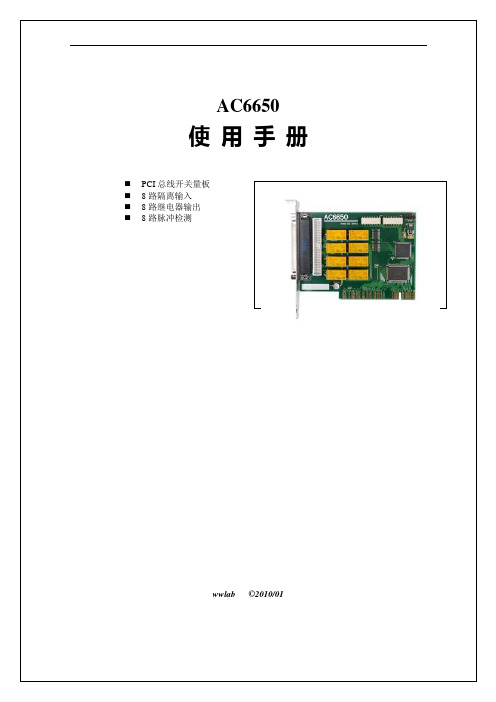
ac6650手册
- 格式:doc
- 大小:248.00 KB
- 文档页数:15

Additional ResourcesThese documents contain additional information concerning related products from Rockwell Automation.Y ou can view or download publications at /literature/. T o order paper copies of technical documentation, contact your local Allen-Bradley distributor or Rockwell Automation sales representative.Product OverviewThe PowerFlex 750-Series is a robust family of AC drives that provide ease of use, flexibility, and performance for a variety of industrial applications. The PowerFlex 753 provides general purpose control for applications ranging up to 350 Hp and 250 kW. The PowerFlex 755 provides maximum flexibility and performance ranging up to 2000 Hp and 1500 kW.Maximize your productivity by taking advantage of the following key features offered in the PowerFlex 750-Series:•DeviceLogix ™ – Embedded control technology that supports the manipulation of discrete outputs and drive control functions, while using discrete inputs and drive status information onboard the drive.•Predict ive Diagnost ics – Allows the drive to keep track of informationthat affects the life of its cooling fans and relay outputs. The drive can also be programmed to monitor the run time hours for machine or motor bearings.•Opt ion Cards – Each drive has a slot-based architecture. Supported hardware control options are common for both products, to help reduce your inventory and spare parts requirements.•Safe T orque-Off and Safe Speed Monitor – provides a choice for safety levels depending on your application requirements.•Communications – The PowerFlex 755 comes with a built-in Ethernet port. Ethernet can easily be added to the PowerFlex 753 with a communication module.TitlePublicationPowerFlex 750-Series Drive Installation Instructions 750-IN001PowerFlex 750-Series Programming Manual750-PM001Enhanced PowerFlex 7-Class Human Interface Module (HIM) User Manual 20HIM-UM001PowerFlex 750-Series Safe Torque Off User Manual750-UM002Safe Speed Monitor Option Module for PowerFlex 750-Series AC Drives Reference Manual 750-RM001PowerFlex 7-Class Network Communication Adapter User Manuals 750COM-UM Dynamic Braking Resistor CalculatorPFLEX-AT001Wiring and Grounding Guidelines for PWM AC DrivesDRIVES-IN001Preventive Maintenance of Industrial Control and Drive System EquipmentDRIVES-TD001Safety Guidelines for the Application, Installation and Maintenance of Solid State ControlSGI-1.1Catalog Number ExplanationCertifications and SpecificationsCertificationsABS (Frames 2…8, 400/480V AC)American Bureau of Shipping Certificate 11-HS743429-PDAC-Tick Australian Communications and Media AuthorityIn conformity with the following:Radiocommunications Act: 1992Radiocommunications Standard: 2008Radiocommunications Labelling Notice: 2008Standards applied:EN 61800-3:2004c-UL-us Listed to UL508C and CAN/CSA-C22.2 No. 14-05 (does not apply to 21G drives with enclosure code “P” or “W”).CE In conformity with the following European Directives:EMC Directive (2004/108/EC)Low Voltage Directive (2006/95/EC)Standards applied:EN 61800-3:2004EN 61800-5-1:2007EPRI/SEMI F47Electric Power Research InstituteCertified compliant with the following standards:SEMI F47IEC 61000-4-34GOST-R (Frames 2…8, 400/480V AC)Russian GOST-R Certificate no.POCC US.ME92.H00040Lloyds Register (Frames 2…8, 400/480V AC)Lloyd’s Register Type Approval Certificate 11/60008RINA (Frames 2…8, 400/480V AC)RINA Certificate ELE349811CSTÜV TÜV Rheinland - Certification applies to 20-750-S and 20-750-S1 Safety Options when installed in drive.Standards applied:EN 61800-3:2004EN 61800-5-2:2007EN 61800-5-1:2007EN 61508 PARTS 1-7:2000EN ISO 13849-1:2008EN 62061:2005EN ISO 13849-2:2003EN 60204-1:2006Approximate DimensionsDimension Drawing IndexFrame Description Page 1IP20, NEMA/UL Type Open69 2IP20, NEMA/UL Type Open69 Flange Mount69IP54, NEMA/UL Type 1270 3IP20, NEMA/UL Open Type70 Flange Mount71IP54, NEMA/UL Type 1272 4IP20, NEMA/UL Open Type72 Flange Mount73IP54, NEMA/UL Type 1274 5IP20, NEMA/UL Open Type74 Flange Mount75IP54, NEMA/UL Type 1276 6IP00, NEMA/UL Open Type77 Flange Mount78IP54, NEMA/UL Type 1279 7IP00, NEMA/UL Open Type80 Flange Mount81NEMA/UL Type 182IP54, NEMA/UL Type 1283 8MCC Style Cabinet, 600 mm (23.6 in.) Deep - IP2084 MCC Style Cabinet, 800 mm (31.5 in.) Deep - IP2085MCC Style Cabinet with Cabinet Option Bay, 600 mm (23.6 in.) Deep - IP2086MCC Style Cabinet with Wiring Bay, 600 mm (23.6 in.) Deep - IP2087MCC Style Cabinet with Cabinet Option Bay, 800 mm (31.5 in.) Deep - IP2088MCC Style Cabinet, 800 mm (31.5 in.) Deep - IP5489MCC Style Cabinet with Cabinet Option Bay, 800 mm (31.5 in.) Deep - IP5490MCC Style Cabinet with Wiring Bay, 800 mm (31.5 in.) Deep - IP5491MCC Style Cabinet with Cabinet Option Bay and Wiring Bay, 800 mm (31.5 in.) Deep - IP5492Open Style - AC Input93Open Style - DC Input94 9MCC Style Cabinet, 600 mm (23.6 in.) Deep - IP2095 MCC Style Cabinet, 800 mm (31.5 in.) Deep - IP2096MCC Style Cabinet with Cabinet Option Bay, 800 mm (31.5 in.) Deep - IP2097MCC Style Cabinet with Wiring Bay, 600 mm (23.6 in.) Deep - IP2098MCC Style Cabinet, 800 mm (31.5 in.) Deep - IP5499MCC Style Cabinet with Cabinet Option Bay, 800 mm (31.5 in.) Deep - IP54100MCC Style Cabinet with Wiring Bay, 800 mm (31.5 in.) Deep - IP54101MCC Style Cabinet with Cabinet Option Bay and Wiring Bay, 800 mm (31.5 in.) Deep - IP54102Open Style - AC Input103Open Style - DC Input104 10MCC Style Cabinet, 600 mm (23.6 in.) Deep - IP20105 MCC Style Cabinet, 800 mm (31.5 in.) Deep - IP20106MCC Style Cabinet with Cabinet Option Bay, 800 mm (31.5 in.) Deep - IP20107MCC Style Cabinet with Wiring Bay, 600 mm (31.5 in.) Deep - IP20108MCC Style Cabinet 800 mm (31.5 in.) Deep - IP54109Open Style - AC Input110Open Style - DC Input111 1…6NEMA/UL Type 1 Kit112 1…5NEMA/UL Type 1 Bottom View113 1…5EMC Plate Kit114Drive OptionsHuman Interface ModulesSpecifications - Human Interface ModulesDescription Cat. No.No HIM (Blank Plate)20-HIM-A0Enhanced, LCD, Full Numeric, Handheld/Local (Drive Mount, Frames 1…5)(1)(1)Select for Frames 2…5 IP54, NEMA/UL Type 12 drives.20-HIM-A6Enhanced, LCD, Full Numeric, IP66 NEMA Type 4X/12 (for indoor use only)(2)(3)(2)Use with Frames 6…7 IP54, NEMA/UL Type 12 drives.(3)Includes a 1202-C30 interface cable (3 meters) for connection to drive.20-HIM-C6S20-HIM-A6 (1)(1)NOTE: This is a product of category C2 according to IEC 61800-3. In a domestic environment this product may cause radio interference in which case supplementary mitigation measures may be required.20-HIM-C6S (1)Drive Protocol: Data Rates:Drive Peripheral Interface (DPI)125 kbps or 500 kbpsConsumption Drive (DPI)::140 mA at 12V DC supplied by the Host Drive Dimensions - H x W x D 20-HIM-A6:20-HIM-C6S:116 x 70 x 16 mm (4.57 x 2.75 x 0.63 in.)180 x 93 x 25 mm (7.08 x 3.66 x 0.98 in.)Weight:91 g (3.2 oz.)173 g (5.7 oz.)Temperature Operating:Storage:0…50 °C (32…122 °F)-40…85 °C (-40…185 °F)Relative Humidity:5…95% non-condensingAtmosphere:Important: The module must not be installed in an area where the ambient atmosphere contains volatile or corrosive gas, vapors or dust. If the module is not going to be installed for a period of time, it must be stored in an area where it will not be exposed to a corrosive atmosphere.UV Radiation The HIM is not UV rated.Vibration Operating:Non-Operating: 2.5 G at 5…2000 Hz 5 G at 5…2000 HzShock Operating:Non-Operating:30 G peak acceleration, 11 (±1) ms pulse width 50 G peak acceleration, 11 (±1) ms pulse width UL c-UL CE C-Tick FCC ID ICUL508CCAN / CSA C22.2 No. 14EN61800-3EN61800-3––Blank Plate 20-HIM-A620-HIM-C6S。


Base part number Package TypeStandard Pack Orderable Part NumberForm QuantityIRGP6650DPbF TO-247AC Tube 25 IRGP6650DPbFIRGP6650D-EPbF TO-247AD Tube 25 IRGP6650D-EPbFAbsolute Maximum RatingsParameter Max. UnitsV CESCollector-to-Emitter Voltage 600 VI C @ T C = 25°C Continuous Collector Current 80 I C @ T C = 100°C Continuous Collector Current 50 I CM Pulse Collector Current, V GE = 15V 105I LMClamped Inductive Load Current, V GE = 20V ① 140 I FRM @ T C = 100°C Diode Repetitive Peak Forward Current ④⑥ 25I FM Diode Maximum Forward Current ④ 140 V GEContinuous Gate-to-Emitter Voltage ±20 V P D @ T C = 25°C Maximum Power Dissipation 306WP D @ T C = 100°C Maximum Power Dissipation 153 T J Operating Junction and -40 to +175 °C T STG Storage Temperature Range Soldering Temperature, for 10 sec. 300 (0.063 in. (1.6mm) from case)Mounting Torque, 6-32 or M3 Screw 10 lbf·in (1.1 N·m)A Thermal ResistanceParameterMin. Typ. Max. Units R θJC (IGBT) Thermal Resistance Junction-to-Case-(each IGBT) ②––– ––– 0.49 °C/WR θCSThermal Resistance, Case-to-Sink (flat, greased surface) ––– 0.24 ––– R θJA Thermal Resistance, Junction-to-Ambient (typical socket mount) ––– ––– 40 R θJC (Diode) Thermal Resistance Junction-to-Case-(each Diode) ②––– ––– 3.35 V CES = 600VI C = 50A, T C =100°Ct SC ≥ 5µs, T J(max) = 175°CV CE(ON) typ. = 1.65V @ I C = 35AApplications ∙ Welding∙ H Bridge ConvertersFeaturesBenefitsLow V CE(ON) and Switching LossesHigh Efficiency in a Wide Range of Applications Optimized Diode for Full Bridge Hard Switch Converters Optimized for Welding and H Bridge Converters Square RBSOA and Maximum Temperature of 175°C Improved Reliability due to Rugged Hard Switching Performance and High Power Capability 5µs Short CircuitEnables Short Circuit Protection Operation Positive V CE (ON) Temperature Co-efficient Excellent Current Sharing in Parallel Operation Lead-free, RoHS compliant Environmentally friendlyG C E Gate Collector EmitterG CE CCGC E Insulated Gate Bipolar Transistor with Ultrafast Soft Recovery DiodeIRGP6650DPbF TO ‐247ACIRGP6650D ‐EPbF TO ‐247ADEGn-channelCElectrical Characteristics @ T J = 25°C (unless otherwise specified)Parameter Min. Typ. Max. Units Conditions V (BR)CES Collector-to-Emitter Breakdown Voltage 600 — — V V GE = 0V, I C = 100µA ③∆V (BR)CES /∆T J Temperature Coeff. of Breakdown Voltage— 0.45 — V/°C V GE = 0V, I C = 1.0mA (25°C-175°C) V CE(on) Collector-to-Emitter Saturation Voltage — 1.65 1.95 V I C = 35A, V GE = 15V, T J = 25°C— 2.05 — I C = 35A, V GE = 15V, T J = 150°C— 2.10 — I C = 35A, V GE = 15V, T J = 175°CV GE(th)Gate Threshold Voltage 4.0 — 6.5 V V CE = V GE , I C = 1.0mA ∆V GE(th)/∆T J Threshold Voltage Temperature Coeff.— -18 — mV/°C V CE = V GE , I C = 1.0mA (25°C-175°C) gfe Forward Transconductance — 22 — S V CE = 50V, I C = 35A, PW = 20µsI CES Collector-to-Emitter Leakage Current — 1.0 50 V GE= 0V, V CE = 600V— 600 — V GE = 0V, V CE = 600V, T J = 175°C I GES Gate-to-Emitter Leakage Current— — ±100 nA V GE = ±20V V FDiode Forward Voltage Drop — 1.80 2.80 V I F = 8A— 1.30 — I F = 8A, T J = 175°CSwitching Characteristics @ T J = 25°C (unless otherwise specified)Parameter Min. Typ. Max Units ConditionsQ g Total Gate Charge (turn-on) — 75 — nC I C = 35A Q ge Gate-to-Emitter Charge (turn-on) — 20 — V GE = 15VQ gc Gate-to-Collector Charge (turn-on) — 30 —V CC = 400V E on Turn-On Switching Loss — 300 —µJ I C = 35A, V CC = 400V, V GE =15V R G = 10Ω, L=210µH, T J = 25°C Energy losses include tail & diode reverse recovery ⑤E off Turn-Off Switching Loss — 630 —E total Total Switching Loss — 930 — t d(on) Turn-On delay time — 40 —ns t rRise time — 30 —t d(off) Turn-Off delay time — 105 — t fFall time — 20 — E on Turn-On Switching Loss — 640 —µJ I C = 35A, V CC = 400V, V GE =15V R G = 10Ω, L=210µH, T J = 175°C Energy losses include tail & diode reverse recovery ⑤E off Turn-Off Switching Loss — 930 —E total Total Switching Loss — 1570 — t d(on) Turn-On delay time — 40 —ns t rRise time — 30 —t d(off) Turn-Off delay time — 120 — t f Fall time — 60 — C ies Input Capacitance — 2220 — V GE = 0VC oes Output Capacitance — 130 —pF V CC = 30V C res Reverse Transfer Capacitance — 65 —f = 1.0MHz RBSOA Reverse Bias Safe Operating AreaT J = 175°C, I C = 140A FULL SQUARE V CC = 480V, Vp ≤ 600V V GE = +20V to 0V SCSOA Short Circuit Safe Operating Area 5 — — µs T J = 150°C,V CC = 400V, Vp ≤ 600V V GE = +15V to 0VErec Reverse Recovery Energy of the Diode— 165 — µJ T J = 175°Ct rr Diode Reverse Recovery Time — 50 — ns V CC = 400V, I F = 8A, V GE = 15V I rrPeak Reverse Recovery Current—14—ARg = 22Ω, L=1.0mH, Ls=150nHµA Notes:① V CC = 80% (V CES ), V GE = 20V, Rg = 10Ω, L=210µH. ② R θ is measured at T J of approximately 90°C.③ Refer to AN-1086 for guidelines for measuring V (BR)CES safely. ④ Pulse width limited by max. junction temperature.⑤ Values influenced by parasitic L and C in measurement. ⑥fsw =40KHz, refer to figure 26.Fig. 5 - Reverse Bias SOA T J = 175°C; V GE = 20V255075100125150175T C (°C)20406080100I C (A )f , Frequency ( kHz )L o a d C u r r e n t( A )Fig. 1 - Typical Load Current vs. Frequency(Load Current = I RMS of fundamental)255075100125150175T C (°C)50100150200250300350P t o t (W )Fig. 4 - Forward SOAT C = 25°C; T J ≤ 175°C; V GE= 15V 1101001000V CE (V)I C (A)Fig. 2 - Maximum DC Collector Current vs.Case Temperature101001000V CE (V)I C (A )Fig. 3 - Power Dissipation vs.Case TemperatureFig. 10 - Typical V CE vs. V GET J = -40°CFig. 11 - Typical V CE vs. V GET J = 25°C1400246810V (V)0.01.02.03.04.05.06.0V F (V)5101520V GE (V)02468V C E (V )5101520V GE (V)02468V C E (V )Fig. 9 - Typ. Diode Forward Voltage DropFig. 16 - Typ. Energy Loss vs. R GT J = 175°C; V CE = 400V, I CE = 35A; V GE = 15V Fig. 17 - Typ. Switching Time vs. R G T J = 175°C; V CE = 400V, I CE = 35A; V GE = 15V5101520V GE (V)8246810121416V GE (V)010203040506070I C(A)1101001000S w i c h i n g T i m e (n s )Fig. 13 - Typ. Transfer CharacteristicsV CE= 50V; tp = 20µs20406080100R G (Ω)101001000S wi c h i n g T i m e (n s )Fig. 15 - Typ. Switching Time vs. I CT J = 175°C; V CE = 400V, R G = 10Ω; V GE = 15V10203040506070I C (A)01000200030004000E n e r g y (μJ )Fig. 12 - Typical V CE vs. V GET J = 175°CFig. 14 - Typ. Energy Loss vs. I CT J = 175°C; ; V CE = 400V, R G = 10Ω; V GE = 15V20406080100Rg (Ω)50010001500200025003000E n e r g y (μJ )Fig. 22 - Typ. Diode E RR vs. I FT J = 175°CFig. 20 - Typ. Diode I RR vs. di F /dt V CC = 400V; V GE = 15V; I F = 8A; T J = 175°C246810121416I F (A)05101520I R R (A )20406080100R G (Ω)0481216I R R (A )Fig. 19 - Typ. Diode I RR vs. R GT J = 175°C200400600800di F/dt (A/µs)46810121416I R R (A )Fig. 18 - Typ. Diode I RR vs. I FT J = 175°C246810121416I F (A)050100150200250E n e r g y (µJ )2004006008001000di F /dt (A/µs)2004006008001000Q R R (n C)Fig. 21 - Typ. Diode Q RR vs. di F /dt V CC = 400V; V GE = 15V; T J = 175°C910111213141516V GE (V)048121620T i m e (µs )50100150200250Current (A)Fig. 23 - V GE vs. Short Circuit TimeV CC = 400V; T C = 150°CFig. 27 - Maximum Transient Thermal Impedance, Junction-to-Case (IGBT)V CE (V)Fig. 24 - Typ. Capacitance vs. V CE V GE = 0V; f = 1MHzQ G , Total Gate Charge (nC)Fig. 25 - Typical Gate Charge vs. V GEI CE= 35At 1, Rectangular Pulse Duration (sec)Fig 26. Maximum Diode Repetitive Forward Peak Current vs. Case Temperature100125150175Case Temperature (°C)t1 , Rectangular Pulse Duration (sec)Fig. 28 - Maximum Transient Thermal Impedance, Junction-to-Case (DIODE)Fig.C.T.1 - Gate Charge Circuit (turn-off) Fig.C.T.2 - RBSOA CircuitFig.C.T.3 - S.C. SOA CircuitFig.C.T.4 - Switching Loss CircuitFig.C.T.5 - Resistive Load CircuitFig.C.T.6 - BVCES Filter CircuitLVCCRSHVCCR = VCCFig. WF1 - Typ. Turn-off Loss Waveform@ T J = 175°C using Fig. CT.4Fig. WF2 - Typ. Turn-on Loss Waveform@ T J = 175°C using Fig. CT.4Fig. WF4 - Typ. S.C. Waveform @ T J = 150°C using Fig. CT.3Fig. WF3 - Typ. Diode Recovery Waveform@ T J = 175°C using Fig. CT.4-100102030405060-1000100200300400500600-0.20.20.40.60.8I C E (A )V C E (V )time(µs)90% I CE10% V CE10% I CEEoff Losstf-100102030405060-100100200300400500600-0.20.20.40.60.8I C E (A )V C E (V )time (µs)TEST CURRENT90% I CE10% V CE10%I CEtrEon Loss-20-15-10-5051015-0.200.000.200.400.60I F (A )time (µS)Peak I RRt RRQ RR-50050100150200250-100100200300400500-10.0-7.5-5.0-2.50.02.55.0V c e (V )Time (uS)V CEI CETO-247AC Package OutlineDimensions are shown in millimeters (inches)YEAR 1 = 2001DATE CODE PART NUMBERINTERNATIONAL LOGO RECTIFIER ASSEMBLY 56 57IRFPE30135HLINE Hindicates "Lead-Free"WEEK 35LOT CODEIN THE ASSEMBLY LINE "H"ASSEMBLED ON WW 35, 2001Notes: This part marking information applies to devices produced after 02/26/2001Note: "P" in assembly line positionEXAMPLE:WITH ASSEMBLY THIS IS AN IRFPE30LOT CODE 5657TO-247AC Part Marking InformationNote: For the most current drawing please refer to IR website at /package/ TO-247AC package is not recommended for Surface Mount Application.TO-247AD Package OutlineIR WORLD HEADQUARTERS: 101 N. Sepulveda Blvd., El Segundo, California 90245, USATo contact International Rectifier, please visit /whoto-call/Qualification Information † Qualification LevelIndustrial(per JEDEC JESD47F)††TO-247ACN/ATO-247ADRoHS Compliant Yes Moisture Sensitivity Level †Qualification standards can be found at International Rectifier’s web site: /product-info/reliability/†† Applicable version of JEDEC standard at the time of product release.Revision HistoryDate Comments∙ Added I FM Diode Maximum Forward Current = 140A with the note ④ on page 1. ∙ Removed note ④ from switching losses test condition on page 2.11/14/2014。


A A-6800说明书精品好文档,推荐学习交流岛津原子吸收分光光度计AA-6800/6650 系列使用说明书(中文版)岛津香港有限公司206-94425CZ岛津原子吸收分光光度计AA-6800F (P/N 206-50500-37,-92,-93)AA-6800G (P/N 206-50700-37,-92,-93)AA-6650F (P/N 206-51200-37,-92,-93)AA-6650G (P/N 206-51300-37,-92,-93)使用说明书软件版本 2.1(C)在使用本产品以前务必仔细阅读使用说明书。
请把使用说明书放在容易取到的地方,以便需要时随时参考。
岛津香港有限公司安全操作须知原子吸收分光光度计是一种定量分析用的分析仪器。
安全使用本仪器,应严格遵守下列规定。
否则可能发生危险。
1.严禁把本机用于上述用途以外的目的。
2.按照使用说明书的操作步骤进行操作。
3.遵循警告和注意事项内的要求。
4.没有岛津办事处直接授权,不要拆卸或修改仪器。
5.修理仪器内部,请立即与岛津办事处联系。
使用说明书关于安装中部分加色的描述仅供岛津授权的维修人员使用。
用户请不要自行安装部件以免不测。
在说明书中关于注意事项的信号含义如下:警告:表示具有潜在的危险,如不避免有可能造成中等程度或重伤,甚至造成死亡。
注意:表示具有潜在的危险,如不避免有可能造成轻伤或导致仪器的损坏。
注:用于提高工作效率或帮助更好的理解。
火焰原子吸收测定事先必须检查是否漏气!漏气检查中如果出现“有漏气勿点火”(如右图)的警告信号有两种可能:1.供应的燃气压力低于所要求的压力2.气体控制单元内可能有漏气现象因此,一旦漏气检查中出现上述信息,请务必不要点火,并迅速采取下列措施:1.检查燃气的供气压力是否满足要求(0.09~0.1兆帕)如果太低,请调高压力到需要的范围然后再次进行漏气检查2.如果燃气压力已经满足要求或压力调高后该警告信号仍然发生,请立即关闭主机和外围设备的电源3.关闭供气单元的主阀和次级压力阀4.尽快与就近的岛津公司代表处联系,在取得资格认证的工程师进行维修保养前请不要使用本机在使用原子吸收分光光度计时,通常要使用高压气体。
SANGFOR SG快速安装手册技术支持说明为了让您在安装,调试、配置、维护和学习SANGFOR设备时,能及时、快速、有效的获得技术支持服务,我们建议您:1.参考本快速安装手册图文指导,帮助你快速的完成部署、安装SANGFOR设备。
如果快速安装手册不能满足您的需要,您可以到SANGFOR技术论坛或官网获得电子版的完整版用户手册或者其他技术资料,以便你获得更详尽的信息。
2.致电您的产品销售商(合同签约商),寻求技术支持。
为了更快速的响应您的服务要求和保证服务质量,您所在地的SANGFOR的产品销售商配备有经过厂家认证的技术工程师,会向您提供快捷的电话咨询、远程调试及必要的上门技术服务。
3.在不紧急的情况下,您可以访问SANGFOR的技术论坛,寻求技术问题的解决方案和办法。
4.致电SANGFOR客服中心,确认最适合您的服务方式和服务提供方,客服中心会在您的技术问题得到解决后,帮助您获得有效的服务信息和服务途径,以便您在后续的产品使用和维护中最有效的享受技术支持服务,及时、有效的解决产品使用中的问题。
SANGFOR技术论坛:公司网址:技术支持服务热线:400-630-6430(手机、固话均可拨打)邮箱:support@目录技术支持说明 (1)目录 (2)声明 (3)前言 (4)第1章SG系列硬件设备的安装 (5)1.1环境要求 (5)1.2电源 (5)1.3产品接口说明 (5)1.4配置与管理 (6)1.5单设备接线方式 (8)1.6双机备份接线方式 (9)第2章SG系列硬件设备部署 (11)2.1路由模式 (12)2.1.1路由模式部署配置案例 (13)2.2网桥模式 (19)2.2.1网桥多网口 (19)2.2.2多网桥 (25)2.2.3DMZ口重定向 (32)2.3旁路模式 (37)2.3.1旁路模式部署配置案例 (38)2.4单臂模式 (43)2.4.1单臂模式部署配置案例 (43)2.5高可用性配置案例 (46)2.5.1多机同步 (46)2.5.2双机维护 (50)第3章基本功能配置 (55)3.1封堵P2P应用配置案例 (55)3.2审计用户上网行为配置案例 (59)3.3限制下载工具的网络流量配置案例 (61)3.4保证重要应用网络流量配置案例 (67)3.5上网加速配置案例 (73)3.6上网代理配置案例 (74)3.7防共享功能配置案例 (75)3.8无线管理配置案例 (78)3.8.1客户网络环境与需求 (78)3.8.2无线基本配置 (79)3.8.3配置开放式无线网络案例 (79)3.8.4配置企业级认证无线网络案例 (82)第4章密码安全风险提示 (86)4.1修改控制台登录密码 (86)声明Copyright©2015深圳市深信服电子科技有限公司及其许可者版权所有,保留一切权利。
NPort 6400/6600Series4/8/16/32-port RS-232/422/485secure terminal serversFeatures and Benefits•LCD panel for easy IP address configuration (standard temp.models)•Secure operation modes for Real COM,TCP Server,TCP Client,PairConnection,Terminal,and Reverse Terminal•Nonstandard baudrates supported with high precision •Port buffers for storing serial data when the Ethernet is offline •Supports IPv6•Ethernet redundancy (STP/RSTP/Turbo Ring)with network module •Generic serial commands supported in Command-by-Command mode •Security features based on IEC 62443CertificationsIntroductionThe NPort®6000is a terminal server that uses the SSL and SSH protocols to transmit encrypted serial data over Ethernet.Up to 32serial devices of any type can be connected to the NPort®6000,using the same IP address.The Ethernet port can be configured for a normal or secure TCP/IP connection.The NPort®6000secure device servers are the right choice for applications that use large numbers of serial devices packed into a small space.Security breaches are intolerable and the NPort®6000Series ensures data transmission integrity with support for DES,3DES,and AES encryption algorithms.Serial devices of any type can be connected to the NPort®6000,and each serial port on the NPort®6000can be configured independently for RS-232,RS-422,or RS-485transmission.No Data Loss If Ethernet Connection FailsThe NPort®6000is a reliable device server that provides users with secure serial-to-Ethernet data transmission and a customer-oriented hardware design.If the Ethernet connection fails,the NPort®6000will queue all serial data in its internal 64KB port buffer.When the Ethernet connection is re-established,the NPort®6000will immediately release all data in the buffer in the order that it was ers can increase the port buffer size by installing an SD card.LCD Panel Makes Configuration EasyThe NPort®6600has a built-in LCD panel for configuration.The panel displays the server name,serial number,and IP address,and any of the device server’s configuration parameters,such as IP address,netmask,and gateway address,can be updated easily and quickly.Note:The LCD panel is only available with standard-temperature models.Adjustable Resistor Values for RS-485CommunicationThe NPort®6600provides adjustable termination,pull high,and pull low resistors for RS-485communication.In some criticalenvironments,termination resistors may be needed to prevent the reflection of serial signals,and the pull high and pull low resistors may need adjusting to maintain the integrity of the electrical signal.Since no set of resistor values works for every environment,the NPort®6600allows manual adjustment of the resistor values for each serial port using built-in DIP switches.SpecificationsMemorySD Slot Up to32GB(SD2.0compatible)Input/Output InterfaceAlarm Contact Channels Resistive load:1A@24VDCEthernet Interface10/100BaseT(X)Ports(RJ45connector)1Auto MDI/MDI-X connectionMagnetic Isolation Protection 1.5kV(built-in)Optical Fiber800Typical Distance4km5km40kmWavelength Typical(nm)13001310TX Range(nm)1260to13601280to1340 RX Range(nm)1100to16001100to1600Optical Power TX Range(dBm)-10to-200to-5 RX Range(dBm)-3to-32-3to-34 Link Budget(dB)1229 Dispersion Penalty(dB)31Note:When connecting a single-mode fiber transceiver,we recommend using anattenuator to prevent damage caused by excessive optical power.Note:Compute the“typical distance”of a specific fiber transceiver as follows:Linkbudget(dB)>dispersion penalty(dB)+total link loss(dB).Ethernet Software FeaturesConfiguration Options Web Console(HTTP/HTTPS),Serial Console,Telnet/SSH Console,Windows Utility Management ARP,BOOTP,DHCP Client,DNS,HTTP,IPv4/IPv6,SMTP,SNMPv1/v2c/v3,TCP/IP,Telnet,UDP,PPPOE,ICMPWindows Real COM Drivers Windows95/98/ME/NT/2000,Windows XP/2003/Vista/2008/7/8/8.1/10(x86/x64),Windows2008R2/2012/2012R2(x64),Windows Embedded CE5.0/6.0,Windows XPEmbeddedLinux Real TTY Drivers Kernel versions:2.4.x,2.6.x,3.x,4.x,and5.xFixed TTY Drivers SCO UNIX,SCO OpenServer,UnixWare7,QNX4.25,QNX6.x,Solaris10,FreeBSD,AIX5.x,HP-UX11i,Mac OS XAndroid API Android3.1.x and laterMIB MIB-IIUnicast Routing RIPV1/V2,Static RouteAuthentication Local Account Accessibility,RADIUS,TACACS+Serial InterfaceConnector NPort6600Series:8-pin RJ45NPort6450Series:DB9maleNo.of Ports NPort6450Series:4NPort6600-8Series:8NPort6600-16Series:16NPort6600-32Series:32Serial Standards NPort6610Series:RS-232NPort6450/6650Series:RS-232,RS-422,RS-485Secure Operation Modes Reverse SSH,Secure Pair Connection,Secure Real COM,Secure TCP Client,SecureTCP Server,SSHStandard Operation Modes Disabled,Ethernet Modem,Pair Connection,PPP,Printer,Real COM,Reverse Telnet,RFC2217,TCP Client,TCP Server,Terminal,UDPBaudrate50bps to921.6kbps(supports non-standard baudrates)Console Port NPort6600Series:RS-232(TxD,RxD,GND),8-pin RJ45(19200,n,8,1)Data Bits5,6,7,8Stop Bits1,1.5,2Parity None,Even,Odd,Space,MarkFlow Control RTS/CTS,DTR/DSR,XON/XOFFPull High/Low Resistor for RS-4851kilo-ohm,150kilo-ohmsRS-485Data Direction Control ADDC®(automatic data direction control)Terminator for RS-485NPort6600Series:120ohmsSerial SignalsRS-232TxD,RxD,RTS,CTS,DTR,DSR,DCD,GNDRS-422Tx+,Tx-,Rx+,Rx-,GNDRS-485-4w Tx+,Tx-,Rx+,Rx-,GNDRS-485-2w Data+,Data-,GNDPower ParametersInput Current NPort6450Series:730mA@12VDCNPort6600SeriesDC Models:293mA@48VDC,200mA@88VDCAC Models:140mA@100VAC(8ports),192mA@100VAC(16ports),285mA@100VAC(32ports)Input Voltage NPort6450Series:12to48VDCNPort6600SeriesAC Models:100to240VACDC Models:±48VDC(20to72VDC,-20to-72VDC),110VDC(88to300VDC) ReliabilityAutomatic Reboot Trigger Built-in WDTAlert Tools Built-in buzzer and RTC(real-time clock)Physical CharacteristicsHousing MetalDimensions(with ears)NPort6450Series:181x103x35mm(7.13x4.06x1.38in)NPort6600Series:480x195x44mm(18.9x7.68x1.73in) Dimensions(without ears)NPort6450Series:158x103x35mm(6.22x4.06x1.38in)NPort6600Series:440x195x44mm(17.32x7.68x1.73in) Weight NPort6450Series:1,020g(2.25lb)NPort6600-8Series:3,460g(7.63lb)NPort6600-16Series:3,580g(7.89lb)NPort6600-32Series:3,600g(7.94lb)Interactive Interface LCD panel display(non-T models only)Push buttons for configuration(non-T models only) Installation NPort6450Series:Desktop,DIN-rail mounting,Wall mountingNPort6600Series:Rack mounting(with optional kit) Environmental LimitsOperating Temperature Standard Models:0to55°C(32to131°F)Wide Temp.Models:-40to75°C(-40to167°F)High-Voltage Wide Temp.Models:-40to85°C(-40to185°F) Storage Temperature(package included)Standard/Wide Temp.Models:-40to75°C(-40to167°F)High-Voltage Wide Temp.Models:-40to85°C(-40to185°F) Ambient Relative Humidity5to95%(non-condensing)Standards and CertificationsEMC EN55032/24EMI CISPR32,FCC Part15B Class AEMS NPort6450Series:IEC61000-4-2ESD:Contact:4kV;Air:8kVIEC61000-4-3RS:80MHz to1GHz:3V/mIEC61000-4-4EFT:Power:1kV;Signal:0.5kVIEC61000-4-5Surge:Power:1kV;Signal:1kVIEC61000-4-6CS:150kHz to80MHz:3V/m;Signal:3V/mIEC61000-4-8PFMFIEC61000-4-11DIPsNPort6600Series(except-48V/-HV models):IEC61000-4-2ESD:Contact:4kV;Air:8kVIEC61000-4-3RS:80MHz to1GHz:3V/mIEC61000-4-4EFT:Power1kV;Signal0.5kVIEC61000-4-5Surge:Power:2kVIEC61000-4-6CS:150kHz to80MHz:3V/m;Signal:3V/mIEC61000-4-8PFMFIEC61000-4-11DIPsNPort6600-48V Series:IEC61000-4-2ESD:Contact:4kV;Air:8kVIEC61000-4-3RS:80MHz to1GHz:3V/mIEC61000-4-4EFT:Power:1kV;Signal:0.5kVIEC61000-4-5Surge:Power:1kVIEC61000-4-6CS:150kHz to80MHz:3V/m;Signal:3V/mIEC61000-4-8PFMFNPort6650-HV Series:IEC61000-4-2ESD:Contact:4kV;Air:8kVIEC61000-4-3RS:80MHz to1GHz:3V/mIEC61000-4-4EFT:Power:4kV;Signal:2kVIEC61000-4-5Surge:Power:2kVIEC61000-4-6CS:150kHz to80MHz:3V/m;Signal:3V/mIEC61000-4-8PFMFTraffic Control NEMA TS2Vibration IEC60068-2-6Freefall IEC60068-2-34DeclarationGreen Product RoHS,CRoHS,WEEEMTBFTime NPort6450Series:850,905hrsNPort6610-8Series:135,891hrsNPort6610-16Series:102,373hrsNPort6610-32Series:68,707hrsNPort6650-8Series:636,600hrsNPort6650-16Series:439,673hrsNPort6650-32Series:310,078hrsNPort6650-8-HV-T:501,171hrsNPort6650-16-HV-T:380,006hrsNPort6650-32-HV-T:290,914hrsStandards NPort6450Series:Telcordia(Bellcore)Standard TR/SRNPort6600Series:Telcordia(Bellcore)StandardWarrantyWarranty Period5yearsDetails See /warrantyPackage ContentsDevice1x NPort6400/6600Series terminal serverInstallation Kit2x rack-mounting ear(NPort6600Series)Cable1x DB9male to RJ458-pin(NPort6600Series)Power Supply1x power cable,suitable for your region(AC models except-T models)1x power adapter,suitable for your region(NPort6450) Documentation1x quick installation guide1x warranty cardDimensionsNPort6450NPort6600Ordering InformationModel Name No.of Serial Ports Serial Standards Serial Interface Operating Temp.Input Voltage NPort64504RS-232/422/485DB9male0to55°C12to48VDC NPort6450-T4RS-232/422/485DB9male-40to75°C12to48VDC NPort6610-88RS-2328-pin RJ450to55°C100-240VACNPort6610-8-48V8RS-2328-pin RJ450to55°C 48VDC;+20to+72 VDC,-20to-72VDCNPort6610-1616RS-2328-pin RJ450to55°C100-240VACNPort6610-16-48V16RS-2328-pin RJ450to55°C 48VDC;+20to+72 VDC,-20to-72VDCNPort6610-3232RS-2328-pin RJ450to55°C100-240VACNPort6610-32-48V32RS-2328-pin RJ450to55°C 48VDC;+20to+72 VDC,-20to-72VDCNPort6650-88RS-232/422/4858-pin RJ450to55°C100-240VAC NPort6650-8-T8RS-232/422/4858-pin RJ45-40to75°C100-240VACNPort6650-8-HV-T8RS-232/422/4858-pin RJ45-40to85°C 110VDC;88to300VDCNPort6650-8-48V8RS-232/422/4858-pin RJ450to55°C 48VDC;+20to+72 VDC,-20to-72VDCNPort6650-1616RS-232/422/4858-pin RJ450to55°C100-240VACNPort6650-16-48V16RS-232/422/4858-pin RJ450to55°C 48VDC;+20to+72 VDC,-20to-72VDCNPort6650-16-T16RS-232/422/4858-pin RJ45-40to75°C100-240VACNPort6650-16-HV-T16RS-232/422/4858-pin RJ45-40to85°C 110VDC;88to300VDCNPort6650-3232RS-232/422/4858-pin RJ450to55°C100-240VACNPort6650-32-48V32RS-232/422/4858-pin RJ450to55°C 48VDC;+20to+72 VDC,-20to-72VDCNPort6650-32-HV-T32RS-232/422/4858-pin RJ45-40to85°C 110VDC;88to300VDCAccessories(sold separately)CablesCBL-RJ45F25-1508-pin RJ45to DB25female serial cable,1.5mApplicable Models:NPort6650-8-48VNPort6650-8-HV-TNPort6650-32-48VNPort6650-32-HV-TNPort6650-16-HV-TNPort6650-16-48VCBL-RJ45F9-1508-pin RJ45to DB9female serial cable,1.5mApplicable Models:NPort6650-16NPort6650-8-48VNPort6610-32-48VNPort6650-16-48VNPort6650-16-TNPort6650-8NPort6650-8-HV-TNPort6610-16NPort6650-32-HV-TNPort6610-8NPort6650-32-48VNPort6650-16-HV-TNPort6610-32NPort6610-16-48VNPort6610-8-48VNPort6650-8-TNPort6650-32CBL-RJ45M25-1508-pin RJ45to DB25male serial cable,1.5mApplicable Models:NPort6650-8NPort6650-8-HV-TNPort6610-16NPort6650-8-TNPort6610-32-48VNPort6650-16-TNPort6650-8-48VNPort6650-16-HV-TNPort6650-16-48VNPort6650-16NPort6650-32-HV-TNPort6650-32NPort6610-8NPort6610-8-48VNPort6650-32-48VNPort6610-16-48VNPort6610-32CBL-RJ45M9-1508-pin RJ45to DB9male serial cable,1.5mApplicable Models:NPort6610-32-48VNPort6610-8-48VNPort6650-32NPort6650-8NPort6650-32-HV-TNPort6610-16NPort6610-8NPort6650-16-HV-TNPort6610-16-48VNPort6610-32NPort6650-32-48VNPort6650-8-TNPort6650-16-TNPort6650-8-HV-TNPort6650-16-48VCBL-RJ45SF25-1508-pin RJ45to DB25female serial cable with shielding,1.5mApplicable Models:NPort6610-16NPort6610-32-48VNPort6610-32NPort6650-32NPort6650-32-48VNPort6610-8NPort6650-16-TNPort6610-16-48VNPort6650-32-HV-TNPort6650-16NPort6650-8NPort6650-16-48VNPort6650-16-HV-TNPort6650-8-TNPort6610-8-48VNPort6650-8-48VNPort6650-8-HV-TCBL-RJ45SF9-1508-pin RJ45to DB25male serial cable with shielding,1.5mApplicable Models:NPort6610-32NPort6650-8NPort6650-32NPort6650-8-HV-TNPort6650-16-HV-TNPort6610-8NPort6650-16NPort6610-16NPort6650-16-48VNPort6650-8-TNPort6650-8-48VNPort6650-32-48VNPort6650-16-TNPort6610-32-48VNPort6610-8-48VNPort6610-16-48VNPort6650-32-HV-TCBL-RJ45SM25-1508-pin RJ45to DB9female serial cable with shielding,1.5mApplicable Models:NPort6650-8NPort6650-8-48VNPort6610-32-48VNPort6650-8-TNPort6650-32-HV-TNPort6650-32NPort6610-16NPort6650-16NPort6610-8-48VNPort6650-16-TNPort6610-8NPort6610-16-48VNPort6650-16-48VNPort6610-32NPort6650-8-HV-TNPort6650-32-48VNPort6650-16-HV-TCBL-RJ45SM9-1508-pin RJ45to DB9male serial cable with shielding,1.5mNPort6650-8-TNPort6610-32-48VNPort6610-16-48VNPort6650-16-48VNPort6610-8NPort6650-32-HV-TNPort6610-8-48VNPort6650-16-HV-TNPort6650-32-48VNPort6650-8-HV-TNPort6650-16-TNPort6610-32NPort6650-8-48VNPort6650-16NPort6650-8ConnectorsMini DB9F-to-TB DB9female to terminal block connectorApplicable Models:NPort6450NPort6450-TDIN-Rail Mounting KitsDK35A DIN-rail mounting kit,35mmApplicable Models:NPort6450NPort6450-TExpansion ModulesNM-TX01110/100BaseTX portNM-TX01-T110/100BaseTX port,-40to75°C operating temperatureNM-TX02210/100BaseTX portsNM-TX02-T210/100BaseTX ports,-40to75°C operating temperatureNM-FX01-M-SC1100BaseFX port,multi-mode,SC connectorNM-FX01-M-SC-T1100BaseFX port,multi-mode,SC connector,-40to75°C operating temperatureNM-FX01-S-SC1100BaseFX port,single-mode,SC connectorNM-FX01-S-SC-T1100BaseFX port,single-mode,SC connector,-40to75°C operating temperatureNM-FX02-M-SC2100BaseFX ports,multi-mode,SC connectorNM-FX02-M-SC-T2100BaseFX ports,multi-mode,SC connector,-40to75°C operating temperatureNM-FX02-S-SC2100BaseFX ports,single-mode,SC connectorNM-FX02-S-SC-T2100BaseFX ports,single-mode,SC connector,-40to75°C operating temperaturePower AdaptersPWR-12125-DT-S2Desktop power supply(requires power cord),12VDC,1.25A,100-240VAC,0to40°C operatingtemperatureApplicable Models:NPort6450NPort6450-TPWR-12150-AU-SA-T Locking barrel plug,12VDC,1.5A,100-240VAC,Australia(AU)plug,-40to75°C operatingtemperatureApplicable Models:NPort6450-TNPort6650-16-HV-TNPort6650-16-TNPort6650-32-HV-TNPort6650-8-HV-TPWR-12150-CN-SA-T Wide-temperature(-40to75°C)locking barrel plug,12VDC,1.5A,100to240VAC,China(CN)plugApplicable Models:NPort6450-TNPort6650-16-HV-TNPort6650-16-TNPort6650-32-HV-TNPort6650-8-HV-TNPort6650-8-TPWR-12150-EU-SA-T Locking barrel plug,12VDC,1.5A,100-240VAC,Continental Europe(EU)plug,-40to75°C operatingtemperatureApplicable Models:NPort6450-TNPort6650-16-HV-TNPort6650-16-TNPort6650-32-HV-TNPort6650-8-HV-TNPort6650-8-TPWR-12150-UK-SA-T Locking barrel plug,12VDC,1.5A,100-240VAC,United Kingdom(UK)plug,-40to75°C operatingtemperatureApplicable Models:NPort6450-TNPort6650-16-HV-TNPort6650-16-TNPort6650-32-HV-TNPort6650-8-HV-TNPort6650-8-TPWR-12150-USJP-SA-T Locking barrel plug,12VDC1.5A,100-240VAC,United States/Japan(US/JP)plug,-40to75°Coperating temperatureApplicable Models:NPort6450-TNPort6650-16-HV-TNPort6650-16-TNPort6650-32-HV-TNPort6650-8-HV-TNPort6650-8-TPower CordsPWC-C13AU-3B-183Power cord with Australian(AU)plug,1.83mApplicable Models:NPort6610-16-48VNPort6650-8-48VNPort6650-16-HV-TNPort6610-8-48VNPort6610-32NPort6650-8NPort6650-32NPort6610-32-48VNPort6610-8NPort6650-8-TNPort6610-16NPort6650-16-48VNPort6650-8-HV-TNPort6650-32-48VNPort6650-32-HV-TNPort6650-16NPort6650-16-TPWC-C13CN-3B-183Power cord with three-prong China(CN)plug,1.83mApplicable Models:NPort6650-32NPort6650-8-TNPort6650-8-48VNPort6650-16NPort6650-16-48VNPort6650-16-TNPort6610-32NPort6610-32-48VNPort6650-16-HV-TNPort6610-16-48VNPort6610-8-48VNPort6650-32-48VNPort6610-8NPort6650-32-HV-TPWC-C13EU-3B-183Power cord with Continental Europe(EU)plug,1.83mApplicable Models:NPort6650-8-48VNPort6650-8-HV-TNPort6650-32NPort6650-16NPort6650-16-TNPort6650-16-HV-TNPort6610-32NPort6650-16-48VNPort6610-16-48VNPort6610-8NPort6610-8-48VNPort6650-32-48VNPort6650-32-HV-TNPort6650-8NPort6610-16NPort6610-32-48VNPort6650-8-TPWC-C13JP-3B-183Power cord with Japan(JP)plug,7A/125V,1.83mApplicable Models:NPort6650-16-TNPort6650-8NPort6610-8NPort6650-8-HV-TNPort6650-32NPort6610-8-48VNPort6650-8-TNPort6650-16NPort6610-16-48VNPort6610-32-48VNPort6650-16-HV-TNPort6650-8-48VNPort6610-16NPort6650-16-48VNPort6610-32NPort6650-32-48VNPort6650-32-HV-TPWC-C13UK-3B-183Power cord with United Kingdom(UK)plug,1.83mApplicable Models:NPort6650-16-HV-TNPort6650-16NPort6610-32NPort6610-16NPort6610-8-48VNPort6650-16-TNPort6610-8NPort6610-32-48VNPort6650-8NPort6650-8-TNPort6650-16-48VNPort6650-32NPort6650-32-HV-TNPort6650-8-48VNPort6650-32-48VNPort6650-8-HV-TNPort6610-16-48VPWC-C13US-3B-183Power cord with United States(US)plug,1.83mApplicable Models:NPort6650-32NPort6610-8NPort6650-8-HV-TNPort6610-32NPort6610-8-48VNPort6610-16NPort6610-16-48VNPort6650-16-48VNPort6650-8-48VNPort6650-8-TNPort6610-32-48VNPort6650-32-48VNPort6650-32-HV-TNPort6650-16-HV-TNPort6650-16-TPWC-C7AU-2B-183Power cord with Australian(AU)plug,2.5A/250V,1.83mApplicable Models:NPort6450-TNPort6450PWC-C7EU-2B-183Power cord with Continental Europe(EU)plug,2.5A/250V,1.83mApplicable Models:NPort6450NPort6450-TPWC-C7JP-2B-183Power cord with Japan(JP)plug,7A/125V,1.83mApplicable Models:NPort6450-TNPort6450PWC-C7UK-2B-183Power cord with United Kingdom(UK)plug,2.5A/250V,1.83mApplicable Models:NPort6450-TNPort6450PWC-C7US-2B-183Power cord with United States(US)plug,10A/125V,1.83mApplicable Models:NPort6450NPort6450-TPower WiringCBL-PJ21NOPEN-BK-30Locking barrel plug to bare-wire cableApplicable Models:NPort6450Rack-Mounting KitsWK-44-01Rack-mounting kit,2L-shaped plates,8screws,44x57.5x1.6mmApplicable Models:NPort6610-8NPort6610-32NPort6610-32-48VNPort6610-16-48VNPort6610-16NPort6610-8-48VNPort6650-16-TNPort6650-16-48VNPort6650-16NPort6650-32-HV-TNPort6650-16-HV-TNPort6650-8-TNPort6650-32NPort6650-32-48VNPort6650-8-HV-TNPort6650-8NPort6650-8-48VWall-Mounting KitsWK-35-01Wall-mounting kit,2plates,6screwsApplicable Models:NPort6450-TNPort6450©Moxa Inc.All rights reserved.Updated Feb17,2020.This document and any portion thereof may not be reproduced or used in any manner whatsoever without the express written permission of Moxa Inc.Product specifications subject to change without notice.Visit our website for the most up-to-date product information.。
Application Note Product: CE Lite, AC 650VDocument Number:3502Keywords: Upload / DownloadIf you have questions, please call the Product Support Group at (704) 588-3246.ObjectiveTo Upload / Download a ConfigEd Lite configuration to or from your PC.EquipmentA computer with ConfigEd Lite software installed and communications cable (CM351909). ProcedureUpload a Configuration from the Drive into the computer1. Launch ConfigEd Lite on the computer. Refer to ConfigEd Lite manual RG352747.2. Connect the communications cable from the comm port on the computer to the P3 port on the drive.Note: In the CE Lite software verify the baud rate is 19200 under Command::Comms3. Verify communications to the drive by going under COMMAND::GET INFO. After clicking on GET INFOThe drive you are connected should be shown on the scratch pad.Note: If an error message appeared when you clicked on GET INFO, verify comm port and settings. 4. UnderFILE::NEW , open the default configuration for the drive that appeared in the scratch pad. (Example: 65V Version 4.x (not running) - choose DEFAULT4.65V .) 5. Under the Command menu click on “update.” 6. After the program has finished updating, Save the file.Note: Do not change the extension of the file.Download a Configuration to the drive1. Launch ConfigEd Lite on the computer. Refer to ConfigEd Lite manual RG352747.2. UnderFILE::OPEN , open the desired configuration to install. (Example: Winder1.65V)Note:In the CE Lite software verify the baud rate is 19200 under Command::Comms.3. Under the Command menu click on “full install.”650VApplicationNote Product:Document Number: 3507 Keywords: EncoderObjectiveTo configure the 650V drive for the Encoder feedback feature.Equipment650V AC drive, Encoder (Single Ended Quadrature) and the software DSELite.ProcedureThe 650V drive has an Encoder function block. The encoder block can be configured as a ‘trim feedback’ which will help improve the steady state speed regulation, when an encoder is mounted to the motor.1.Connect a single ended encoder Channel A to terminal 12 ( Digital Input 6 / ENC A) on the 650Vdrive and connect Channel B to terminal 13 ( Digital Input 7 / ENC B) on the 650V drive. The drive does not have provisions for an encoder supply.ing DSELite, open a ‘default.65V’ template and configure the drive as shown below.3.Also if a connection is made to Digital Input 6 and to Digital Input 7 in the DSELite template, deleteit. There should not be any connections made to these two blocks.4.In the Encoder block, enter in the Lines of the encoder ppr.5.Adjust the PID parameters for best performance.ObjectiveProvide details to convert the wiring changes from the 584S, 584SV, and 605 to a 650V. Equipment650V drive, wiring diagram, drive product manuals, computer with DSELite installed.Procedureunch DSELite on the computer.2.Under File::New, open the default configuration of the drive you have, (example: default4.65V).Ensure that the name on the lower left corner matches the drive you are working on.3.Configure the DSELite file to mask the previous drive application.4.Reference the chart below for assistance to convert the wiring changes.Note: This document only provides information to convert the wiring changes from the previous drive to a 650V based on default templates.If you have questions, please call the Product Support Group at (704) 588-3246.Conversion Table for 584S, 584SV, 605, to 650V Terminal Description 584S Connection584SV Connection 605 Connection 650V Connection Analog Input (Speed) 1 1 2 2 Analog Input (Trim) 2 2 4 3 Analog Input (Current) 3 3 -- --0V Reference 4 4 1 1 Analog Input (Torque Limit) 5 5 -- -- Thermistor 6, 10 6, 10 -- Th1A, Th1B Analog Output (Ramp Output) 7 7 5 5 Analog Output (Load) 8 -- -- --+10V Reference 9 9 3 40V Reference (Analog) 10 10 1 1-10V Reference 11 11 -- -- Health Relay (Contacts) 12 12 12 (+24Vdc only) RL1A Health Relay (Contacts) 13 13 13 RL1B Relay 1 (Contacts) 14 14 14 (+24Vdc only) --Relay 1 (Contacts) 15 15 13 --Relay 2 (Contacts) 16 16 -- --Relay 2 (Contacts) 17 17 -- --+24Vdc Supply 18 18 18 60V Reference (Digital) 19 19 12 1 Digital Input (Run) 20 20 7 7 Digital Input 21 21 Configurable Configurable Digital Input (Direction) 22 22 9 8 Digital Input (External Trip) 18, 23 18, 23 6, 10 -- Digital Input (Jog) 24 24 11 9 Digital Input 25 Configurable Configurable ConfigurableDigital Input 26 Configurable 16 Configurable**(ENCA) 12 Configurable **(ENCA)Digital Input 27 Configurable 17 Configurable**(ENCB) 13 Configurable**(ENCB)**(ENCA) Encoder Channel A**(ENCB) Encoder Channel BIf you have questions, please call the Product Support Group at (704) 588-3246.Document Number:3501Keywords: Inverse SpeedIf you have questions, please call the Product Support Group at (704) 588-3246.ObjectiveProvide details to configure the 650V for maximum speed with a zero value on the Analog Input.Equipment650V drive, computer with DSELite installed. Procedure1. Launch DSELite on the computer.2. Under File::New , open the default configuration of the drive you have, (example: default4.65V).Ensure that the name on the lower left corner matches the drive you are working on. 3. Using DSELite configure the template as shown below.4. In the template, make sure the App Config / Application is set to display Custom .5. Change the value of Value Function 1/ Input B to –100.00%6. Change the Value Function 1/Type to (A+B+C).7. Change the value of Value Function 2 / Input B to 1.00.8. Change the value of Value Function 2 / Input C to –1.00.9. Change the Value Function 2/ Type to (A*B/C). 10. Change the Reference / Min Speed Clamp to 0.00%.Note: The values of Value Function 1::Input B, Value Function 2::Input B and C can beadjusted to provide opposite speed control.。