基于VHDL语言的数字钟设计
- 格式:docx
- 大小:89.04 KB
- 文档页数:14
基于VHDL的数字钟的设计一、设计目的1、掌握计数器,分频器的工作原理和设计方法;2、掌握数码管的动态扫描译码显示的工作原理和设计方法;3、掌握数字钟的设计方法;4、掌握在EDA开发软件QuartusII环境下基于FPGA/CPLD的数字系统设计方法,掌握该环境下系统的功能仿真、时序仿真、管脚锁定和芯片下载的方法。
二、设计要求1、基本要求(1)设计一个24小时制的数字钟;(2)利用板上数码管显示时、分、秒,要求显示格式为:小时—分钟—秒;(3)利用板上的按键作时钟调整,调整要求为:按下时调整键,“时”迅速增加,并按24小时制(0~~23)规律循环;按下分调整键,“分”迅速增加,并按60分钟制(0~59)规律循环;(4)数字钟可清零、可保持。
2、提高要求(1)能利用EDA系统上的蜂鸣器作整点报时。
从59分55秒时开始报时,每隔一秒报时一次;00分00秒时,进行整点报时。
整点报时声的频率应与其他的报时声频率有明显区别;(2)具有按12小时模式显示与24小时模式显示切换的功能;(3)具有闹钟功能。
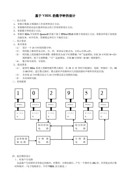
三、系统框图四、底层模块设计1、时基产生电路由晶振产生的频率非常稳定的脉冲,经整形、分频电路后,产生一个频率为1Hz的、非常稳定的计数时钟脉冲。
(电子线路部分,不用VHDL语言描述。
)2、校时电路(二选一数据选择器)LIBRARY ieee;USE ieee.std_logic_1164.all;ENTITY MUX2_1 ISPORT(K,CLK,CI : IN STD_LOGIC;Y : OUT STD_LOGIC);END MUX2_1;ARCHITECTURE b OF MUX2_1 ISBEGINY<=CLK WHEN K='0' ELSE CI;END b;3、计数器(1)24进制计数器1)24进制的VHDL语言程序LIBRARY ieee;USE ieee.std_logic_1164.all;USE ieee.std_logic_unsigned.all;ENTITY COUNT24 ISPORT(CLR : IN STD_LOGIC;EN : IN STD_LOGIC;CLK : IN STD_LOGIC;QL : BUFFER STD_LOGIC_VECTOR(3 downto 0);QH : BUFFER STD_LOGIC_VECTOR(3 downto 0);CO : OUT STD_LOGIC);END COUNT24;ARCHITECTURE a OF COUNT24 ISBEGINPROCESS(CLR,EN,CLK)BEGINIF CLR='0' THENQH<="0000";QL<="0000";ELSIF CLK'EVENT AND CLK='1' THENIF(EN='1')THENIF QH=2 AND QL=3 THENQL<="0000";QH<="0000";ELSEIF QL=9 THENQL<="0000";QH<=QH+1;ELSEQL<=QL+1;END IF;END IF;END IF;END IF;END PROCESS;CO<='0'WHEN QH=2 AND QL=3 ELSE'1';END a;2)仿真波形图1、count24的时序仿真波形3)从设计文件创建模块,默任模块的名称为count24。
课程:CPLD与FPGA设计及应用实验:基于VHDL语言的数字时钟设计学号:*********姓名:**专业:信号与信息处理学院:电子与信息学院2011年12月基于VHDL语言的数字时钟设计一:主要功能1:具有时、分、秒计数显示功能,以24小时循环计时。
2:具有日期和星期显示功能。
3:具有秒表功能4:具有调节日期,星期,小时,分钟,清零的功能。
5:具有定时和闹铃的功能。
二:结构框图三:RTL图四:功能实现4.1分频模块设计本设计使用的输入时钟信号为50Mhz,经过分频产生两路时钟信号,其中一路为微秒计数时钟信号,一路为动态扫描时钟信号。
同时模块有一输入控制信号,其功能是停止微秒计数时钟信号,以实现定时的功能。
输入:clk_in 为50Mhz,setstop为微秒计数时能信号输出:clk_out1为1/60hzclk_out2为1khz源代码如下:library ieee;use ieee.std_logic_1164.all;entity div isport(clk_in,setstop: in std_logic;clk_out1,clk_out2: out std_logic);end entity div;architecture fun of div isconstant a:integer:=8333333;constant b:integer:=49999;signal c:integer range 0 to a;signal d:integer range 0 to b;beginprocess(clk_in,setstop)beginif(clk_in 'event and clk_in='1') thenif(( c+7500000)<a and setstop='1') then c<=c+1;clk_out1<='1';else c<=0;clk_out1<='0';end if;end if;end process;process(clk_in)beginif(clk_in 'event and clk_in='1') thenif d<=b then d<=d+1; clk_out2<='1';else d<=0;clk_out2<='0';end if;end if;end process;end fun;4.2计时模块设计4.2.1 微秒计时模块计数器的第一个模块为微秒计时模块,其实质为一个六十进制计数器。
信息与通信工程学院数字电路与逻辑设计实验题目:基于VHDL语言的数字钟设计班级:姓名:学号:日期:指导教师:一.摘要数字钟是一个将“时”、“分”、“秒”显示于人的视觉器官的计时装置。
它的基本功能是计时,计时周期为24小时,显示满刻度23时59分59秒;或者计时周期为12小时并配有上下午指示,显示满刻度为11时59分59秒,通过六个七段数码管显示出来。
本实验主要在理论分析和具体的软硬件实现上,基于VHDL语言编写源代码,使用软件Quartus II 进行处理,再配合具体电路连接,实现一个多功能的数字钟。
关键词:数字钟;VHDL语言;七段数码管二.设计任务要求设计实现一个数字钟。
1.24小时制,显示刻度从0:0:0到23:59:59 。
2.12小时制,显示刻度从0:0:0到11:59:59 。
3.12/24小时制可切换,12小时制下上下午有不同显示(上午发光二极管不亮,下午发光二极管亮)。
4.可手动校对时间,能对时和分进行校正。
5.整点报时功能。
6.闹铃功能,可设置闹铃时间,当计时到预定时间时,蜂鸣器发出闹铃信号,闹铃时间为5秒,可提前终止闹铃。
7.可认为设置时间为倒计时模式8.可切到屏保模式,六个数码管显示为“supper”字样。
三.设计思路和总体设计框图1.设计思路程序设计主要分为四个模块,第一部分,做分频器,分出一秒的时钟用来计数,再分出一个中频时钟用来扫描显示数码管,我选择的频率是50kHZ;第二部分,做计数器,秒随时钟沿计数进1,分钟随着秒计数60次进一,而小时,由于有12/24小时制的切换,时的计数有两个信号来进行,一个信号hour1是分60进一在0到23循环计数,另一个信号hour2是分60进一在0到11循环计数;第三部分,做扫描显示六个七段数码管,通过选通信号6矢量cat来依次使六个数码管亮,数码管每两位对应相应的时分秒;第四部分,其他输入输出单元,比如数字钟的时间修正,闹铃等,这些都是基于前三个部分,做起来难度不大。
基于VHDL语言的数字钟设计摘要:我们现在是在第二十一世纪,是电子信息时代,EDA技术推广。
尤其在电子信息,各行业的通信方面,自动控制方面,在计算机等方面的重要性越来越起到举足轻重的地位。
作为一个学习电子科学与技术专业的学生,我们必须不断的了解更多的关于硬件描述语言等产品的信息,这就要求我们对VHDL语言有个全面的认识。
本设计采用VHDL语言,在QuartusII为操作平台,该软件可以调试,也可以实现软件的模拟仿真,初步实现了设计目标。
这个程序使用的语言为VHDL,这是一种硬件描述语言。
对QUARTUSII有更深的了解,对今后工作、学习等都会有所帮助]1[。
与传统的硬件设计方法相比,传统的硬件设计所实用的芯片比较多,有太多的电路图要连接,所以连线较多,会很麻烦,并且在设计的过程中出现错误后也很难检查出来。
使用汇编语言来实现对数字钟的控制相对来说比较容易,并且连线也很简单,出错后易于校验。
使用VHDL语言设计仿真技术,可以在计算机上实现,所以它可以大大缩短系统开发的时间。
可以来尝试使用VHDL作为进行数字钟的设计。
设计一个数字时钟,能够以24小时循环显示小时、分钟,秒计数;具有时间清零,时、分设置功能;也具有整点报时的功能。
要求我的论文分为秒模块,分模块,以及与时模块,并且也有显示扫描模块,还有整点报时模块,译码器等。
在Quartus上可以进行编译仿真波形。
如果接到EDA平台上也可以进行仿真]2[。
通过本次的论文设计,不仅巩固了我所学到的专业知识,而且对数字系统的理解也随之加深,从刚开始接触到论文的时候慢慢的学习才渐渐的了解VHDL语言,更加深了对以前EDA的掌握,现在也对QUARTUSII软件也能够完成许多的操作。
并且能完成仿真。
关键词:EDA技术; QUARTUSII; VHDL语言; 数字时钟The design of digital clock based on VHDL languageAbstract:Now we are in the 21st century,which is not only the high-tech era, but also the era of electronic information.EDA technology continues to in-depth and extension.Especially in electronic information, ,automatic control, Playing a pivotal position,which is more and more importance.As a study of electronic science and technology major students, we must constantly learn more information about the hardware description language, and other products, This requests us to have a comprehensive understanding of the language of VHDL]3[.This project design using VHDL language, as for the HDL( hardware description language), QUARTUSII as program operation platform, the development of program debugging and running, through waveform simulation, Design goal was preliminarily realized.The use of the program for the VHDL language, which is a kind of HDL(hardware description language),Let us had a deeper step in the comprehensive application of QUARTUSII use, my future study and work to bring a lot of guidance from this paper design. Compared with the traditional design method of hardware, the traditional hardware design practical chip is more, there are too many circuit diagram to connect, so the attachment is more, it will be very troublesome, and after an error in the process of design is to check ing assembly language to achieve control of the digital clock is relatively easy, and the attachment is simple, which easy to check.It can use VHDL language design simulation technology, which can be implemented on the computer, so it can greatly shorten the time of the system development.It also can try to use VHDL as for the design of digital clock.It design a digital clock, with 24 hours display hours, minutes, seconds count;With time, hours, minutes setting function;It also has the function of the hour.For my thesis is divided into second module, module, and module, and that also have show scanning module, and hour module, decoder, etc.It depend on Quartus compile the simulation waveform.If received the EDA platform can also be simulated.Deepen understanding of the digital system, from the beginning when in contact with the paper slowly learning to gradually understand the VHDL language, punctuate the grasp of the EDA before, now also the software QUARTUSII is also able to complete the operation of many.And can complete the simulation.Keywords: EDA technology; QUARTUSII; VHDL language; Digital clock安徽三联学院毕业论文目录第一章引言 (1)1.1 设计背景 (1)1.2 设计目的 (1)1.3 设计的内容 (2)第二章主要方案介绍 (4)2.1 方案一 (4)2.2 方案二 (4)第三章系统硬件描述语言............................ 错误!未定义书签。
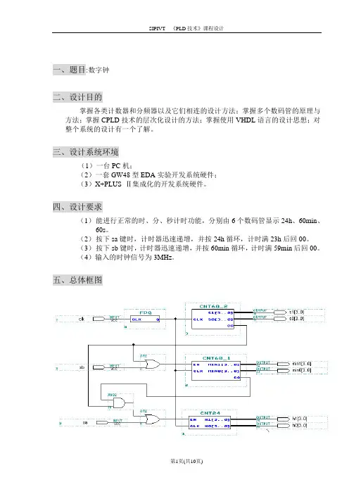
一、题目:数字钟二、设计目的掌握各类计数器和分频器以及它们相连的设计方法;掌握多个数码管的原理与方法;掌握CPLD技术的层次化设计的方法;掌握使用VHDL语言的设计思想;对整个系统的设计有一个了解。
三、设计系统环境(1)一台PC机;(2)一套GW48型EDA实验开发系统硬件;(3)X+PLUS Ⅱ集成化的开发系统硬件。
四、设计要求(1)能进行正常的时、分、秒计时功能,分别由6个数码管显示24h、60min、60s。
(2)按下sa键时,计时器迅速递增,并按24h循环,计时满23h后回00。
(3)按下sb键时,计时器迅速递增,并按60min循环,计时满59min后回00。
(4)输入的时钟信号为3MHz。
五、总体框图六、模块及模块功能(1)模块CNT60_2 该模块为60进制计数器,计时输出为秒的数值,在计时到59时送出进位信号CO,因为硬件有延时,所以模块CNT60_2在此模块变为00时加1,符合实际。
A、模块B、程序library ieee;use ieee.std_logic_1164.all;use ieee.std_logic_unsigned.all;entity cnt60_2 isport(clk:in std_logic;s1,s0:out std_logic_vector(3 downto 0);co:out std_logic);end cnt60_2;architecture behav of cnt60_2 isbeginprocess(clk)variable cnt1,cnt0:std_logic_vector(3 downto 0);beginif clk'event and clk='1' thenif cnt1="0101" and cnt0="1000" thenco<='1';cnt0:="1001";elsif cnt0<"1001" thencnt0:=cnt0+1;else cnt0:="0000";if cnt1<"0101" thencnt1:=cnt1+1;else cnt1:="0000";co<='0';end if;end if;end if;s1<=cnt1;s0<=cnt0;end process;end behav;C、流程图D、波形仿真(2)模块CNT60_1 该模块为60进制计数器,计时输出为分的数值,在EN信号有效且时钟到来时,计数器加1。
基于VHDL的多功效数字钟设计陈述021215班卫时章02121451一.设计请求1.具有以二十四小时制计时.显示.整点报时.时光设置和闹钟的功效.2.设计精度请求为1秒.二.设计情况:Quartus II三.体系功效描写1.体系输入:时钟旌旗灯号clk采取50MHz;体系状况及较时.准时转换的控制旌旗灯号为k.set,校时复位旌旗灯号为reset,均由按键旌旗灯号产生.2.体系输出:LED显示输出;蜂鸣器声音旌旗灯号输出.3.多功效数字电子钟体系功效的具体描写如下:(一)计时:正常工作状况下,每日按24h计时制计时并显示,蜂鸣器无声,逢整点报时.(二)校时:在计时显示状况下,按下“k”键,进入“小时”待校准状况,若此时按下“set”键,小时开端校准;之后按下“k”键则进入“分”待校准状况;中断按下“k”键则进入“秒”待复零状况;再次按下“k”键数码管显示闹钟时光,并进入闹钟“小时”待校准状况;再次按下“k”键则进入闹钟“分”待校准状况;若再按下“k”键恢复到正常计时显示状况.若校时进程中按下“reset”键,则体系恢复到正常计数状况.(1)“小时”校准状况:在“小时”校准状况下,显示“小时”的数码管以2Hz闪耀,并按下“set”键时以2Hz的频率递增计数.(2)“分”校准状况:在“分”校准状况下,显示“分”的数码管以2Hz闪耀,并按下“set”键时以2Hz的频率递增计数.(3)“秒”校准状况:在“秒复零”状况下,显示“秒”的数码管以2Hz闪耀,并以1Hz的频率递增计数.(4)闹钟“小时”校准状况:在闹钟“小时”校准状况下,显示“小时”的数码管以2Hz闪耀,并按下“set”键时以2Hz的频率递增计数.(5)闹钟“分”校准状况:在闹钟“分”校准状况下,显示“分”的数码管以2Hz闪耀,并按下“set”键时以2Hz的频率递增计数.(三)整点报时:蜂鸣器在“59”分钟的第“51”.“53”.“55”.“57”秒发频率为500Hz的低音,在“59”分钟的第“59”秒发频率为1000Hz的高音,停止时为整点.(四)显示:采取扫描显示方法驱动4个LED数码管显示小时.分,秒由两组led灯以4位BCD 码显示.(五)闹钟:闹钟准不时光到,蜂鸣器发出频率为1000Hz的高音,中断时光为60秒.四.各个模块剖析解释1.分频器模块(freq.vhd)(1)模块解释:输入一个频率为50MHz的CLK,应用计数器分出1KHz的q1KHz,500Hz的q500Hz,2Hz的q2Hz和1Hz的q1Hz.(2)源程序:library ieee;use ieee.std_logic_1164.all;use ieee.std_logic_unsigned.all;entity freq isport (CLK: in std_logic ; --输入时钟旌旗灯号q1KHz: buffer std_logic;q500Hz: buffer std_logic;q2Hz: buffer std_logic;q1Hz: out std_logic);end freq;architecture bhv of freq isbeginP1KHZ:process(CLK)variable cout:integer:=0;beginif CLK'event and CLK='1' thencout:=cout+1; --每来个时钟上升沿时cout开端计数if cout<=25000 then q1KHz<='0'; --当cout<=25000时,q1KHz输出“0”elsif cout<50000 then q1KHz<='1'; --当25000<cout<=50000时,q1KHzelse cout:=0; --输出“1”,完成1KHz 频率输出end if;end if;end process;P500HZ:process(q1KHz) --q1KHz作为输入旌旗灯号,分出q500Hzvariable cout:integer:=0;beginif q1KHz'event and q1KHz='1' thencout:=cout+1;if cout=1 then q500Hz<='0'; --二分频elsif cout=2 then cout:=0;q500Hz<='1';end if;end if;end process;P2HZ:process(q500Hz)variable cout:integer:=0;beginif q500Hz'event and q500Hz='1' then cout:=cout+1;if cout<=125 then q2Hz<='0';elsif cout<250 then q2Hz<='1';else cout:=0;end if;end if;end process;P1HZ:process(q2Hz)variable cout:integer:=0;beginif q2Hz'event and q2Hz='1' thencout:=cout+1;if cout=1 then q1Hz<='0';elsif cout=2 then cout:=0;q1Hz<='1'; end if;end if;end process;end bhv;(3)模块图:2.控制器模块(contral.vhd)(1)模块解释:输入端口k,set键来控制6个状况,这六个状况分离是:显示计不时光状况,调计时的时.分.秒的3个状况,调闹铃的时.分的3个状况,reset键是复位键,用往返到显示计不时光的状况.(2)波形仿真图:(3)模块图:3、二选一模块(mux21a.vhd)(1)源程序:library ieee;use ieee.std_logic_1164.all;use ieee.std_logic_unsigned.all;entity mux21a isport(a,b,s:in bit;y:out bit);end entity mux21a;architecture one of mux21a isbeginprocess(a,b,s)beginif s='0' theny<=a; --若s=0,y输出a,反之输出b. else y<=b;end if;end process;end architecture one;(2)仿真波形图:(3)模块图:4、计时模块a.秒计时(second.vhd)(1)仿真波形图:(2)模块图:b.分计时(minute.vhd)(1)仿真波形图:(2)模块图:c.小时计时(hour.vhd)(1)仿真波形图:(2)模块图:d.闹钟分计时(cntm60b.vhd)(1)仿真波形图:(2)模块图:e.闹钟小时计时(cnth24b.vhd)(1)仿真波形图:(2)模块图:5.闹钟比较模块(compare.vhd)(1)模块解释:比较正常计数时光与闹钟准不时光是否相等,若相等,compout输出“1”,反之输出“0”.(2)仿真波形图:(3)模块图:6.报时模块(bell.vhd)(1)模块解释:该模块既实现了整点报时的功效,又实现了闹铃的功效,蜂鸣器经由过程所选频率的不合,而发出不合的声音.(2)仿真波形图:(3)模块图:7.控制显示模块(show_con.vhd)(1)模块解释:该模块实现了数码管既可以显示正常时光,又可以显示闹钟时光的功效;调时进程的准时闪耀功效也在此模块中真正实现.(2)源程序:library ieee;use ieee.std_logic_1164.all;use ieee.std_logic_unsigned.all;entity show_con isport(th1,tm1,ts1:in std_logic_vector(7 downto 4);th0,tm0,ts0:in std_logic_vector(3 downto 0);bh1,bm1:in std_logic_vector(7 downto 4);bh0,bm0:in std_logic_vector(3 downto 0);sec1,min1,h1: out std_logic_vector(7 downto 4);sec0,min0,h0: out std_logic_vector(3 downto 0);q2Hz,flashs,flashh,flashm,sel_show:in std_logic); end show_con;architecture rtl of show_con isbeginprocess(th1,tm1,ts1,th0,tm0,ts0,bh1,bm1,bh0,bm0,q2Hz,flas hs,flashh,flashm,sel_show)beginif sel_show='0'thenif ( flashh='1'and q2Hz='1')thenh1<="1111";h0<="1111"; --显示小时数码管以2Hz闪耀min1<=tm1;min0<=tm0;sec1<=ts1;sec0<=ts0;elsif (flashm='1'and q2Hz='1')thenh1<=th1;h0<=th0;min1<="1111";min0<="1111";sec1<=ts1;sec0<=ts0;elsif (flashs='1'and q2Hz='1')thenh1<=th1;h0<=th0;min1<=tm1;min0<=tm0;sec1<="1111";sec0<="1111";elseh1<=th1;h0<=th0;min1<=tm1;min0<=tm0;sec1<=ts1;sec0<=ts0;end if;elsif sel_show='1'then--若sel_show为“1”,数码管显示闹钟时光if(flashh='1' and q2Hz='1')thenh1<="1111";h0<="1111";min1<=bm1;min0<=bm0;sec1<="0000";sec0<="0000";elsif ( flashm='1' and q2Hz='1')thenh1<=bh1;h0<=bh0;min1<="1111";min0<="1111";sec1<="0000";sec0<="0000";elseh1<=bh1;h0<=bh0;min1<=bm1;min0<=bm0;sec1<="0000";sec0<="0000";end if ;end if;end process;end rtl;(3)模块图:8.动态扫描显示模块(scan_led.vhd)(1)模块解释:由4组输入旌旗灯号和输出旌旗灯号进而实现了时钟时.分的动态显示.(2)源程序:library ieee;use ieee.std_logic_1164.all;use ieee.std_logic_unsigned.all;entity scan_led isport(clk1:in std_logic;h0:in std_logic_vector(3 downto 0);h1:in std_logic_vector(7 downto 4);min0:in std_logic_vector(3 downto 0);min1:in std_logic_vector(7 downto 4);ML:out std_logic_vector(7 downto 0);MH:out std_logic_vector(7 downto 0);HL:out std_logic_vector(7 downto 0);HH:out std_logic_vector(7 downto 0));end scan_led;architecture one of scan_led issignal cnt4:std_logic_vector(1 downto 0);signal a: std_logic_vector(3 downto 0) ;beginp1:process(clk1)beginif clk1'event and clk1 ='1' thencnt4<=cnt4+1;if cnt4=3 thencnt4<="00";end if;end if;end process p1;p2:process(cnt4,h1,h0,min1,min0)begincase cnt4 is --控制数码管位选when "00"=>case min0 iswhen "0000"=>ML<="11000000";when "0001"=>ML<="11111001";when "0010"=>ML<="10100100";when "0011"=>ML<="10110000";when "0100"=>ML<="10011001";when "0101"=>ML<="10010010";when "0110"=>ML<="10000010";when "0111"=>ML<="11111000";when "1000"=>ML<="10000000";when "1001"=>ML<="10010000";when others=>NULL;end case;when "01"=>case min1 iswhen "0000"=>MH<="11000000"; when "0001"=>MH<="11111001";when "0010"=>MH<="10100100";when "0011"=>MH<="10110000";when "0100"=>MH<="10011001";when "0101"=>MH<="10010010";when "0110"=>MH<="10000010";when "0111"=>MH<="11111000";when "1000"=>MH<="10000000";when "1001"=>MH<="10010000";when others=>NULL;end case;when "10"=>case h0 iswhen "0000"=>HL<="11000000"; when "0001"=>HL<="11111001";when "0010"=>HL<="10100100";when "0011"=>HL<="10110000";when "0100"=>HL<="10011001";when "0101"=>HL<="10010010";when "0110"=>HL<="10000010";when "0111"=>HL<="11111000";when "1000"=>HL<="10000000";when "1001"=>HL<="10010000";when others=>NULL;end case;when "11"=>case h1 iswhen "0000"=>HH<="11000000"; when "0001"=>HH<="11111001";when "0010"=>HH<="10100100";when "0011"=>HH<="10110000";when "0100"=>HH<="10011001";when "0101"=>HH<="10010010";when "0110"=>HH<="10000010";when "0111"=>HH<="11111000";when "1000"=>HH<="10000000";when "1001"=>HH<="10010000";when others=>NULL;end case;when others =>null;end case;end process p2;end one;(3)模块图:五、端口设定k:button2 ,set:button1 ,reset:button0 ;Bell:SW1 用于开关蜂鸣器;六.顶层电路图七、心得领会此次的数字钟设计重在于按键的控制和各个模块代码的编写,固然能把键盘接口和各个模块的代码编写出来,并能正常显示,但对于各个模块的优化设计还有必定的缺点和缺少,比方对按键消抖等细节处并未作出优化.经由此次数字钟的设计,我确切从中学到许多的器械.起首,经由过程VHDL硬件说话的进修,我充分熟悉到了功效模块若何用说话实现,让我初步懂得到了一个数字电路用硬件说话设计的方法和设计思惟.其次,也让我深深地领会到实践的主要性,起先我学VHDL说话的时刻,只是学得书本上的常识,经由此次课程设计,经由过程对模块的说话实现,对于VHDL说话我有了更深的熟悉.并且在程序错误的发明和纠正的进程中,我得到了更多的收成,也确切让我提高了许多.再次,当我碰到一些问题的时刻,就教先生,和同窗们一路评论辩论,令我受益颇多!最后,这个多功效数字电子钟是自我创造与汲取借鉴配合感化的产品,是自我尽力的成果.这让我对数字电路的设计充满了信念.固然课程设计已经停止,但这其实不代表着我已经真正控制了VHDL说话,仍需中断进修!。
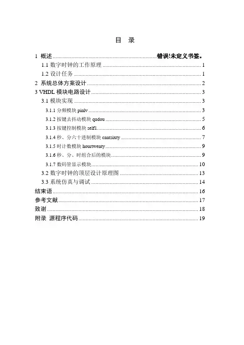
目录1 概述...................................................................... 错误!未定义书签。
1.1数字时钟的工作原理 (1)1.2设计任务 (1)2 系统总体方案设计 (2)3 VHDL模块电路设计 (3)3.1模块实现 (3)3.1.1分频模块pinlv (3)3.1.2按键去抖动模块qudou (5)3.1.3按键控制模块self1 (6)3.1.4秒、分六十进制模块cantsixty (7)3.1.5时计数模块hourtwenty (9)3.1.6秒、分、时组合后的模块 (9)3.1.7数码管显示模块 (10)3.2数字时钟的顶层设计原理图 (13)3.3系统仿真与调试 (14)结束语 (16)参考文献 (17)致谢 (18)附录源程序代码 (19)1 概述1.1数字时钟的工作原理数字钟电路的基本结构由两个60进制计数器和一个24进制计数器组成,分别对秒、分、小时进行计时,当计时到23时59分59秒时,再来一个计数脉冲,则计数器清零,重新开始计时。
秒计数器的计数时钟CLK为1Hz的标准信号,可以由晶振产生的50MHz信号通过分频得到。
当数字钟处于计时状态时,秒计数器的进位输出信号作为分钟计数器的计数信号,分钟计数器的进位输出信号又作为小时计数器的计数信号,每一秒钟发出一个中断给CPU,CPU采用NIOS,它响应中断,并读出小时、分、秒等信息。
CPU对读出的数据译码,使之动态显示在数码管上。
1.2 设计任务设计一个基于VHDL的数字时钟,具体功能要求如下:1.在七段数码管上具有时--分--秒的依次显示。
2.时、分、秒的个位记满十向高位进一,分、秒的十位记满五向高位进一,小时按24进制计数,分、秒按60进制计数。
3.整点报时,当计数到整点时扬声器发出响声。
4.时间设置:可以通过按键手动调节秒和分的数值。
此功能中可通过按键实现整体清零和暂停的功能。
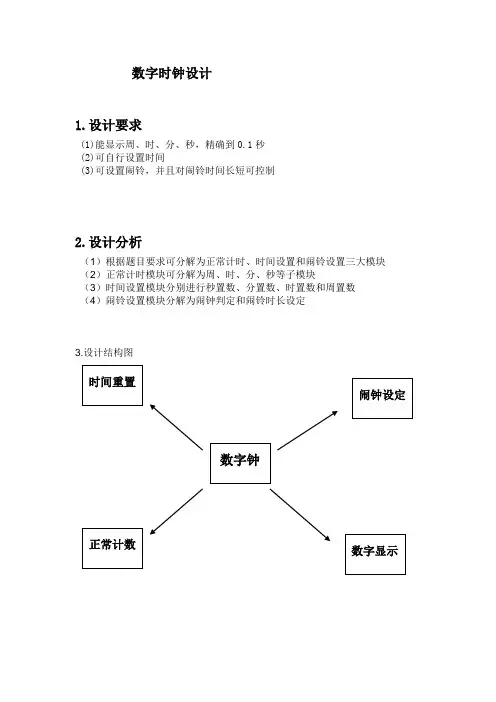
数字时钟设计1.设计要求(1)能显示周、时、分、秒,精确到0.1秒(2)可自行设置时间(3)可设置闹铃,并且对闹铃时间长短可控制2.设计分析(1)根据题目要求可分解为正常计时、时间设置和闹铃设置三大模块(2)正常计时模块可分解为周、时、分、秒等子模块(3)时间设置模块分别进行秒置数、分置数、时置数和周置数(4)闹铃设置模块分解为闹钟判定和闹铃时长设定3.设计结构图4.设计流程图否是否--Second1(秒计数6进制和10进制)Library ieee;Use ieee.std_logic_1164.all;Use ieee.std_logic_unsigned.all;Entity second1 isPort( clks,set:in std_logic;s1,s0:in std_logic_vector(3 downto 0);Secs,Secg: buffer std_logic_vector(3 downto 0);cout1:out std_logic);End second1;Architecture a of second1 isBeginProcess(clks,set)variable ss,sg: std_logic_vector(3 downto 0);--(ss:秒十位;sg秒个位) variable co: std_logic;BeginIf set='1' then ss:=s1; sg:=s0;Elsif clks'event and clks='1' thenif ss="0101" and sg="1001" then ss:="0000"; sg:="0000";co:='1'; elsif sg<"1001" then sg:=sg+1;co:='0';elsif sg="1001" then sg:="0000";ss:=ss+1;co:='0';end if;end if;cout1<=co;-- (进位信号)Secs<=ss;Secg<=sg;end process;End a;仿真波形图:--Min1(分计数器6进制和10进制alm实现整点报时)Library ieee;Use ieee.std_logic_1164.all;Use ieee.std_logic_unsigned.all;Entity min1 isPort(clkm,set:in std_logic;m1:in std_logic_vector(3 downto 0);m0:in std_logic_vector(3 downto 0);mins,ming:out std_logic_vector(3 downto 0);enmin,alarm: out std_logic);End;Architecture a of min1 isBeginProcess(clkm,set)variable ms,mg :std_logic_vector(3 downto 0);variable so,alm :std_logic;Beginif set='0' then ms:=m1;mg:=m0;Elsif clkm'event and clkm='1' thenif ms="0101" and mg="1001" then ms:="0000";mg:="0000"; so :='1'; alm:='1'; elsif mg<"1001" then mg:=mg+1; so :='0';alm:='0';elsif mg="1001" then mg:="0000";ms:=ms+1; so :='0';alm:='0';end if;end if;alarm<=alm;enmin<= so;mins<=ms;ming<=mg;End process;End a;仿真波形图:--Hour1(时计数器4进制与2进制)Library ieee;Use ieee.std_logic_1164.all;Use ieee.std_logic_unsigned.all;Entity hour1 isPort(clkh,set:in std_logic;h1,h0:in std_logic_vector(3 downto 0);hours,hourg:buffer std_logic_vector(3 downto 0);enhour: out std_logic);End;Architecture a of hour1 isBeginProcess(clkh,set)variable hs,hg :std_logic_vector(3 downto 0);variable ho:std_logic;BeginIf set='1' then hs:=h1; hg:=h0;Elsif clkh'event and clkh='1' thenif hs="0010"and hg="0011" then hs:="0000";hg:="0000"; ho :='1'; elsif hg<"1001" then hg:=hg+1; ho :='0';elsif hg="1001" then hg:="0000";hs:=hs+1; ho :='0';end if;end if;hours<=hs;hourg<=hg;enhour<=ho;End process;End a;仿真波形图:Library ieee; (星期计数器,7进制)Use ieee.std_logic_1164.all;Use ieee.std_logic_arith.all;Use ieee.std_logic_unsigned.all;Entity week isPort(clkd,set,reset:in std_logic;d1:in std_logic_vector(3 downto 0); -- ――置数端(星期)day:buffer std_logic_vector(3 downto 0)); -- ――星期输出端end;Architecture a of week isBeginProcess(clkd,reset,set,d1)BeginIf reset='0' then day<="0000"; -- ――对星期计时器清0 Elsif set='0' then day<=d1; -- ――对星期计时器置d1的数Elsif clkd'event and clkd='1' thenIf day=6 then day<="0000"; -- ――重复计数Else day<=day+1;End if;End if;End process;End;仿真波形图:--Second2(秒置数模块,6进制和10进制)Library ieee;Use ieee.std_logic_1164.all;Use ieee.std_logic_unsigned.all;Entity second2 isPort( clks1:in std_logic;Secs,Secg: out std_logic_vector(3 downto 0));End;Architecture a of second2 isBeginProcess(clks1)variable ss,sg: std_logic_vector(3 downto 0);--(ss:秒十位;sg秒个位) Beginif clks1'event and clks1='1' thenif ss="0101" and sg="1001" then ss:="0000"; sg:="0000";elsif sg<"1001" then sg:=sg+1;elsif sg="1001" then sg:="0000";ss:=ss+1;end if;end if;Secs<=ss;Secg<=sg;end process;End a;仿真波形图:--Min2(分置数模块,6进制和10进制)Library ieee;Use ieee.std_logic_1164.all;Use ieee.std_logic_unsigned.all;Entity min2 isPort(clkm1:in std_logic;mins,ming:buffer std_logic_vector(3 downto 0));End;Architecture a of min2 isBeginProcess(clkm1)variable ms,mg :std_logic_vector(3 downto 0);Beginif clkm1'event and clkm1='1' thenif ms="0101" and mg="1001" then ms:="0000";mg:="0000"; elsif mg<"1001" then mg:=mg+1;elsif mg="1001" then mg:="0000";ms:=ms+1;end if;end if;mins<=ms;ming<=mg;End process;End a;仿真波形图:--Hour2(时置数模块,4进制与2进制)Library ieee;Use ieee.std_logic_1164.all;Use ieee.std_logic_unsigned.all;Entity hour2 isPort(clkh1:in std_logic;hours,hourg:buffer std_logic_vector(3 downto 0)); End;Architecture a of hour2 isBeginProcess(clkh1)variable hs,hg :std_logic_vector(3 downto 0);Beginif clkh1'event and clkh1='1' thenif hs="0010"and hg="0011" then hs:="0000";hg:="0000"; elsif hg<"1001" then hg:=hg+1;elsif hg="1001" then hg:="0000";hs:=hs+1;end if;end if;hours<=hs;hourg<=hg;End process;End a;仿真波形图:Library ieee; (星期置数模块,7进制)Use ieee.std_logic_1164.all;Use ieee.std_logic_arith.all;Use ieee.std_logic_unsigned.all;Entity week2 isPort(clkd1:in std_logic;day:buffer std_logic_vector(3 downto 0)); -- ――星期输出端end;Architecture a of week2 isBeginProcess(clkd1)Beginif clkd1'event and clkd1='1' thenIf day=6 then day<="0000"; -- ――重复计数Else day<=day+1;End if;End if;End process;End;仿真波形图:library ieee; (闹钟设置模块)use ieee.std_logic_1164.all;use ieee.std_logic_unsigned.all;entity nz isport(ml,mh:in std_logic_vector(3 downto 0);hl,hh:in std_logic_vector(3 downto 0);mlo,mho:in std_logic_vector(3 downto 0);hlo,hho:in std_logic_vector(3 downto 0);set:in std_logic;output:out std_logic);end nz;architecture behav of nz issignal opt:std_logic;beginprocess(set,ml,mh,hl,hh,mlo,mho,hlo,hho)beginif set='1' thenif(ml=mlo and mh=mho and hl=hlo and hh=hho)then opt<='1';else opt<='0';end if;end if;output<=opt;end process;end behav;library ieee; (闹钟响铃时长设置)use ieee.std_logic_1164.all;use ieee.std_logic_unsigned.all; entity timeset isport( nz:in std_logic;sj:in integer range 0 to 1200;clk:in std_logic;ring:out std_logic);end timeset;architecture behav of timeset is signal count:integer range 0 to 1200; beginprocess(clk)variable co1:std_logic;beginif(clk'event and clk='1') thenif(nz='1') and (count/=sj) thencount<=count+1;co1:='1';else co1:='0';end if;end if;ring<=co1;end process;end behav;闹钟功能模块测试波形图:时间重置模块测试波形图。
基于VHDL的数字电子钟系统设计数字电子钟是一种用数字电路实现的时钟系统,在现代社会逐渐普及。
在这篇文档中,我们将会讨论使用VHDL(可编程硬件描述语言) 设计数字电子钟系统的过程及其原理。
第一步是需求分析。
我们需要决定所设计的数字电子钟系统需要具备哪些功能,例如显示小时、分钟、秒数、日期、星期、闹钟等功能。
同时,还需考虑设计的电子钟具备哪些功能是其他电子钟所没有的,以增强该款电子钟的市场竞争力。
第二步是架构设计。
经过需求分析后,我们需要设计电子钟系统所需的硬件结构。
常见的电子钟由振荡器、时钟、存储器、显示器和控制接口组成。
其中,振荡器用来处理系统时基;时钟用来计时,提供系统时间;存储器负责存储显示数据和助记代码;显示器用来显示时间和日期;而控制接口则提供交互方式,如按键、通讯口等。
第三步是模块设计。
使用VHDL 可以将架构设计分解成更小的模块,进行编写和测试。
这些模块可以包括时钟模块、计数器模块、闹钟模块、数据显示模块等。
其中,时钟模块需要使用振荡器生成时钟信号,计数器模块必须进行计时,生成秒数和毫秒数的输出信号;然后,使用数码管显示模块将这些输出信号转换成可读的时间、日期和闹钟信息;再添加按键输入模块,以便用户操作和控制该电子钟系统。
第四步是系统测试。
在VHDL 设计结束后,需要对数字电子钟系统进行实际测试。
首先,系统测试需要用到仿真软件对整个系统进行验证。
同时,需要将程序下载到FPGA 芯片上,并通过硬件测试验证设计的电子钟系统是否符合需求和规范。
综上所述,设计数字电子钟系统需要遵循一定的流程,包括需求分析、架构设计和模块设计,在这个过程中也需要注重各个模块之间的兼容性和整体性。
这篇文档给大家介绍了使用VHDL 搭建数字电子钟系统的方法,希望广大读者可以从中获得借鉴。
基于VHDL的数字时钟设计邵阳大学课程设计目录1总结11.1数字钟11.2设计任务12系统总体方案设计23 VHDL模块电路设计33.1模块实现33.1.1分频模块吕品33.1.2按键抖动模块qudou 53.1.3按键控制模块self1 63.1.4秒,六进制模块can 60 73 . 1 . 5小时计数模块hour 20 93 . 1 . 6秒,分钟,时间组合模块93.1.7数码管显示模块103.2顶层设计原理图133.3系统模拟和调试14结论16参考17确认18附录源代码191 1.1数字时钟工作原理概述数字时钟电路的基本结构由两个60位计数器和一个24位计数器组成,分别计时秒、分和小时。
当计时达到23: 59分59秒时,另一个计数脉冲将重置计数器并重新开始计时。
第二计数器的计数时钟CLK是1Hz的标准信号,其可以通过将晶体振荡器产生的50MHz信号分频而获得。
当数字时钟处于定时状态时,第二计数器的进位输出信号用作分钟计数器的计数信号,分钟计数器的进位输出信号用作小时计数器的计数信号,并且每秒向中央处理器发送一个中断。
中央处理器采用NIOS,它响应中断并读出小时、分钟、秒钟和其他信息。
中央处理器对读取的数据进行解码,并在数码管上动态显示。
1.2设计任务是设计一个基于VHDL的数字时钟。
具体功能要求如下:1.通过将晶体振荡器产生的50MHz信号除以频率,可以获得七段数码管上带有时间秒计数器的时钟CLK为1Hz的标准信号。
当数字时钟处于定时状态时,第二计数器的进位输出信号用作分钟计数器的计数信号,分钟计数器的进位输出信号用作小时计数器的计数信号,并且每秒向中央处理器发送一个中断。
中央处理器采用NIOS,它响应中断并读出小时、分钟、秒钟和其他信息。
中央处理器对读取的数据进行解码,并在数码管上动态显示。
1.2设计任务是设计一个基于VHDL的数字时钟。
具体功能要求如下:1.在七段数码管上,有时间:你可以通过按键手动调整秒和分钟的值。
基于VHDL语言实现数字电子钟的设计一.设计要求:1、设计容选用适宜的可编程逻辑器件及外围电子元器件,设计一个数字电子钟,利用EDA软件〔QUARTUS Ⅱ〕进展编译及仿真,设计输入可采用VHDL硬件描述语言输入法〕和原理图输入法,并下载到EDA实验开发系统,连接外围电路,完成实际测试。
2、设计要求〔1〕具有时、分、秒计数显示功能。
〔2〕具有清零的功能,且能够对计时系统的小时、分钟进展调整。
〔3〕小时为十二小时制。
二.实验目的:1.通过这次EDA设计中,提高手动能力。
2.深入了解时事时钟的工作原理,以及时事时钟外围硬件设备的组成。
3.掌握多位计数器相连的设计方法。
4.掌握十进制,六进制,二十四进制计数器的设计方法。
5.继续稳固多位共阴极扫描显示数码管的驱动,及编码。
6.掌握扬声器的驱动。
7.LED灯的把戏显示。
8.掌握CPLD技术的层次化设计方法三.实验方案:数字系统的设计采用自顶向下、由粗到细, 逐步分解的设计方法, 最顶层电路是指系统的整体要求, 最下层是具体的逻辑电路的实现。
自顶向下的设计方法将一个复杂的系统逐渐分解成假设干功能模块, 从而进展设计描述, 并且应用EDA 软件平台自动完成各功能模块的逻辑综合与优化, 门级电路的布局, 再下载到硬件中实现设计。
因此对于数字钟来说首先是时分秒的计数功能,然后能显示,附带功能是清零、调整时分。
通过参考EDA 课程设计指导书,现有以下方案:1.作为顶层文件有输入端口:时钟信号,清零按键,调时按键,调分按键;输出端口有:用于接数码管的八段码输出口,扫描用于显示的六个数码管的输出口。
2.底层文件分为:〔1〕时间计数模块。
分秒计数模块计数为60计数,时计数模块为12计数。
〔2〕显示模块。
显示模块由一个六进制计数器模块和一个七段译码器组成。
进制计数器为六选一选择器的选择判断端提供输入信号, 六选一选择器的选择输出端分别接秒个位、秒十位、分个位、分十位和时个位、时十位的选通位用来完成动态扫描显示,同时依次输出秒个位、秒十位、分个位、分十位和时个位、时十位数向给译码模块。
摘要摘要随着EDA技术的发展和应用领域的扩大与深入,EDA技术在电子信息、通信、自动控制及计算机应用领域的重要性日益突出。
EDA技术就是依赖功能强大的计算机,在EDA工具软件平台上,对以硬件描述语言VHDL为系统逻辑描述手段完成的设计文件,自动地完成逻辑优化和仿真测试,直至实现既定的电子线路系统功能。
本文介绍了基于VHDL硬件描述语言设计的多功能数字闹钟的思路和技巧。
在Quartus 11开发环境中编译和仿真了所设计的程序,并逐一调试验证程序的运行状况。
仿真和验证的结果表明,该设计方法切实可行,该数字闹钟可以实现调时定时闹钟播放音乐功能具有一定的实际应用性。
关键词:闹钟 FPGA VHDL目录目录摘要............................................................................................................................. I 目录.......................................................................................................................... III 第一章选题背景.. (1)1.1选题研究内容 (1)1.2课题研究功能 (1)1.3课题相关技术应用 (1)第二章FPGA 简介 (3)2.1FPGA概述 (3)2.1.1 FPGA基本结构 (3)2.2FPGA编程原理 (3)2.3FPGA设计流程 (4)第三章数字闹钟整体方案设计 (7)3.1数字闹钟整体设计 (7)3.1.1数字闹钟各部分作用 (7)3.2数字钟的工作原理 (7)第四章模块电路设计 (9)4.1模块电路图设计 (9)4.2各模块电路设计 (9)第五章实验结果 (16)5.1实验概述 (16)5.2实验仿真结果 (16)第六章总结与展望 (18)研究结论 (18)研究展望 (18)致谢 (20)参考文献 (22)附录1 部分模块代码 (24)附录2 动态扫描模块程序 (33)目录第一章选题背景第一章选题背景1.1选题研究内容设计一个24小时的闹钟,该闹钟由显示屏、数字键、TIME键、ALARM键、扬声器组成。
目录一、EDA技术概述 (2)二、Altera Max+plus II 简介 (5)三、设计任务及要求 (6)3.1设计任务 (6)3.2设计要求 (6)四、系统电路设计 (6)4.1 VHDL语言开发的流程 (6)4.2 系统框架图 (7)4.3电路设计思路与实现 (8)五、电路功能调试及测试 (8)5.1测试内容及步骤 (8)5.2 模块说明 (8)5.3 数字钟各模块连接示意图 (9)5.4功能测试 (9)5.5 小结 (9)六、小结 (9)实物图 (17)参考文献 (18)一、EDA技术概述EDA是电子设计自动化Electronic Design Automation)的缩写,在20世纪90年代初从计算机辅助设计(CAD)、计算机辅助制造CAM)、计算机辅助测试CAT)和计算机辅助工程(CAE)的概念发展而来的。
EDA技术就是以计算机为工具,设计者在EDA 软件平台上,用硬件描述语言VHDL完成设计文件,然后由计算机自动地完成逻辑编译、化简、分割、综合、优化、布局、布线和仿真,直至对于特定目标芯片的适配编译、逻辑映射和编程下载等工作。
EDA 技术伴随着计算机、集成电路、电子系统设计的发展,经历了计算机辅助设计CAD、计算机辅助工程设计CAE 和电子设计自动化EDA 三个发展过程。
EDA 软件工具种类繁多,如:Smartork 、Orcad 、Tango 、Protel 、Workbench(multsim)、Pspice 及各大可编程器件厂商提供的专用开发软件,如:Altera 公司提供的maxpluss2 、Lattice 公司提供的ispDesignExpert/PAC-Designer、Xilinx 公司提供的Foudation Series/webpack 等。
随着电子设计自动化(EDA)技术的不断发展,其含义也不断发生变化,早期的电子设计自动化多指类似Protel 电路版图的设计自动化概念,这种概念仅限于电路元器件与元器件之间即芯片外设计自动化,随着微电子技术的不断发展,当今的EDA 技术更多的是指可编程逻辑器件的设计技术,即芯片内的电路设计自动化。
可编辑修改精选全文完整版一、题目分析1、功能介绍(1)具有时、分、秒计数显示功能,以24小时循环计时。
(2)时钟计数显示时有LED灯的花样显示。
(3)具有调节小时、分钟及清零的功能。
(4)具有整点报时功能。
2、总体方框图3、性能指标及功能设计1)时钟计数:完成时、分、秒的正确计时并且显示所计的数字;对秒、分——60进制计数,即从0到59循环计数,时钟——24进制计数,即从0到23循环计数,并且在数码管上显示数值。
2)时间设置:手动调节分钟、小时,可以对所设计的时钟任意调时间,这样使数字钟真正具有使用功能。
我们可以通过实验板上的键7和键4进行任意的调整,因为我们用的时钟信号均是1HZ的,所以每LED灯变化一次就来一个脉冲,即计数一次。
3)清零功能:reset为复位键,低电平时实现清零功能,高电平时正常计数。
可以根据我们自己任意时间的复位。
4)蜂鸣器在整点时有报时信号产生,蜂鸣器报警。
产生“滴答.滴答”的报警声音。
5)LED灯在时钟显示时有花样显示信号产生。
即根据进位情况,LED不停的闪烁,从而产生“花样”信号。
二、选择方案1、方案选择方案一:根据总体方框图及各部分分配的功能可知,本系统可以由秒计数器、分钟计数器、小时计数器、整点报时、分的调整以及小时的调整和一个顶层文件构成。
采用自顶向下的设计方法,子模块利用VHDL语言设计,顶层文件用原理图的设计方法。
显示:小时采用24进制,而分钟均是采用6进制和10进制的组合。
方案二:根据总体方框图及各部分分配的功能可知,本系统可以由秒计数器、分钟计数器、小时计数器、整点报时、分的调整以及小时的调整和一个顶层文件构成。
采用自顶向下的设计方法,子模块利用VHDL语言设计,顶层文件用原理图的设计方法。
显示:小时采用24进制,而分钟和秒均60进制。
终上所述,考虑到试验时的简单性,故我选择了方案二。
三、细化框图根据自顶向下的方法以及各功能模块的的功能实现上述设计方案应系统细化框图:四、编写程序、仿真和分析1、秒计数器1)VHDL 语言描述程序见附录 2)秒计数器的仿真波形图3)波形分析利用60进制计数器完成00到59的循环计数功能,当秒计数至59时,再来一个时钟脉冲则产生进位输出,即enmin=1;reset 作为复位信号低电平有效,数字时钟控制单元 时调整 分调整使能端信号 CLK 信号时显示 分显示 秒显示24进制 60进制 60进制LED 显示整点报花样显即高电平时正常循环计数,低电平清零。
EDA课程设计——基于VHDL 语言的数字时钟设计(可编辑)(文档可以直接使用,也可根据实际需要修改使用,可编辑推荐下载)一、设计要求 0二、设计原理及框图 01、设计原理 02、结构框图 0三、设计过程 (1)1、模块化设计 (1)2、顶层文件生成 (2)四、仿真调试过程 (3)1、各模块时序仿真图 (3)2、仿真过程中遇到的问题 (4)五、设计体会及收获 (4)一、设计要求1、稳定的显示时、分、秒。
2、当电路发生走时误差时,要求电路有校时功能。
3、电路有整点报时功能。
报时声响为四低一高,最后一响高音正好为整点。
二、设计原理及框图1、设计原理系统框图由六个模块组成,分别为:秒、分、时计数模块,整点报时模块,LED动态显示扫描模块,调时控制模块组成。
其工作原理是:基准脉冲输入信号同时加到秒、分、时、分隔符的脉冲输入端,采用并行计数的方式,秒的进位接到分的使能端上,秒的使能借到分隔符的使能上,分得接到时的使能端上,完成秒、分、时和分隔符的循环计数。
整点报时是根据分的A、B输出同时为0时,整点报时模块输出高电平控制报时。
LED显示扫描模块根据输入的扫描信号CKDSP轮流选通秒、分、时、分隔符的8位八段数码管,LED显示译码器完成计数器输出的BCD的译码。
2、结构框图三、设计过程1、模块化设计(1)秒计时模块秒计时模块由一个60位计数器为主体构成,其输入输出端口组成为:Clk:计时时钟信号Reset:异步清零信号Setmin:分钟设置信号Enmin:使能输出信号Daout[6:0]:BCD码输出(2)分计时模块分计时模块由一个60位计数器为主体构成,其输入输出端口组成为:Clk、clk1:计时时钟信号Reset:异步清零信号Sethour:小时设置信号Enmin:使能输出信号Daout[6:0]:BCD码输出(3)时计时模块时计时模块由24位计数器为主体构成,其输入输出端口组成为:Clk:计时时钟信号Reset:异步清零信号Daout[6:0]:BCD码输出(4)显示模块系统时间输出由六个七段数码管显示。
摘要VHDL作为一种硬件描述语言,可用于数字电路与系统的描述、模拟和自动设计与仿真等,是当今电子设计自动化的核心技术。
本文使用VHDL语言设计了一个数字时钟电路,给出了设计该数字系统的流程和方法。
本设计方法具有硬件描述能力强,设计方法灵活,便于修改等优点,大大降低了数字系统设计的难度,提高了工作效率。
本设计采用EDA技术,以硬件描述语言VHDL为系统逻辑描述手段设计文件,在MAX+PlusⅡ工具软件环境下,采用自顶向下的设计方法,由各个基本模块共同构建了一个基于CPLD的数字钟。
系统主芯片采用EPM7128SLC84,由时钟模块、控制模块、计时模块、数据译码模块、显示以及报时模块组成。
经编译和仿真所设计的程序,在可编程逻辑器件上下载验证,本系统能够完成时、分、秒的分别显示,由按键输入进行数字钟的校时、清零、启停功能。
关键词:硬件描述语言,VHDL,数字电路设计, 数字钟Digital Clock Design Based On The Hardware DescriptionLanguage(VHDL)Author: 。
Tutor: 。
AbstractVHDL can be used to describe,simulate and digital system automatically. Nowdays,it becomes a key technology in automatic electronic design. There is a lot of superiority in this description language.This article introduces the method and the process using VHDL to design a digital system by an example of digital clock dasign. The result given in this paper shows that VHDL is one of the strongest tools in hardware description and it is a flexible among the design method. The method given in this paper can reduce the difficulty of digital system design and improve the work efficiency.The use of EDA design technology, hardware-description language VHDL description logic means for the system design documents, in MaxplusII tools environment, a top-down design, by the various modules together build a CPLD-based digital clock.The main system chips used EPM7128SLC84, make up of the clock module, control module, time module, data decoding module, display and broadcast module. After compiling the design and simulation procedures, the programmable logic device to download verification, the system can complete the hours, minutes and seconds respectively, using keys to modify, cleared , start and stop the digital clock.Key words: Hardware description language,VHDL, Digital circuit design, digital clock目录1 绪论 (1)1.1课题背景 (1)1.2本课题研究的内容 (1)2 总体设计方案 (3)3 单元模块电路设计 (4)3.1时间显示电路模块设计 (4)3.2按键及指示灯电路模块的设计 (5)3.3蜂鸣器及有源晶振电路的设计 (7)3.4CPLD编程下载电路的设计 (8)3.5电源电路的设计 (9)3.5.1变压器次级电压估算 (9)3.5.2 变压器输入功率的计算 (9)3.5.3 滤波电容参数的选取 (10)3.6EPM7128SLC84器件介绍 (10)4 CPLD 编程设计 (11)4.1系统信号的定义及顶层模块 (11)4.2时钟节拍产生模块 (12)4.3模式选择功能模块 (14)4.4快速时间设置功能模块 (16)4.5秒、分、时计时与时间调整模块 (16)4.6闹铃时间设置模块 (18)4.7闹铃与整点报时模块 (19)4.8七段显示译码模块 (20)4.9LED显示模块 (22)5 系统功能仿真 (25)5.1时钟节拍产生模块的仿真波形 (25)5.2模式选择功能模块的仿真波形 (26)5.3闹铃设置功能模块的仿真波形 (27)5.4七段译码功能模块的仿真波形 (28)5.5LED显示功能模块的仿真波形 (30)5.6系统总体功能仿真波形 (31)总结 (32)致谢 (33)参考文献 (34)附录A:基于CPLD的多功能数字钟电路图 (35)附录B:基于VHDL语言的时、分、秒等电路的源码 (36)1绪论1.1 课题背景我们已经进入了数字化和信息化的时代,其特点是各种数字产品的广泛应用。