ADPD188BI集成光学模块及其应用
- 格式:pdf
- 大小:2.80 MB
- 文档页数:6
Rev. 0Circuits from the Lab® reference designs from Analog Devices have been designed and built by Analog Devices engineers. Standard engineering practices have been employed in the design and construction of each circuit, and their function and performance have been tested and verified in a lab environment at room temperature. However, you are solely responsible for testing the circuit anddetermining its suitability and applicability for your use and application. Accordingly, in no event shall Analog Devices be liable for direct, indirect, special, incidental, consequential or punitive damages due to any cause whatsoever connected to the use of any Circuits from the Lab circuits. (Continued on last page) One Technology Way, P.O. Box 9106, Norwood, MA 02062-9106, U.S.A. Tel: /cn Fax: 781.461.3113 © 2020 Analog Devices, Inc. All rights reserved.电路笔记CN-0537Circuits from the Lab TM参考电路是经过测试的参考电路,有助于加速设计,同时简化系统集成,帮助并解决当今模拟、混合信号和RF设计挑战。
Rev. 0Document FeedbackInformation furnished by Analog Devices is believed to be accurate and reliable. However, no responsibility is assumed by Analog Devices for its use, nor for any infringements of patents or other rights of third parties that may result from its use. Specifications subject to change without notice. No license is granted by implication or otherwise under any patent or patent rights of Analog Devices. Trademarks andregistered trademarks are the property of their respective owners.O ne Technology Way, P .O . Box 9106, Norwood, MA 02062-9106, U.S.A.Tel: 781.329.4700 ©2018 Analog Devices, Inc. All rights reserved. Technical Support /cnADI 中文版数据手册是英文版数据手册的译文,敬请谅解翻译中可能存在的语言组织或翻译错误,ADI 不对翻译中存在的差异或由此产生的错误负责。
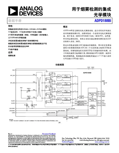
如需确认任何词语的准确性,请参考ADI 提供的最用于烟雾检测的集成光学模块数据手册ADPD188BI特性带集成光学元件的3.8 mm × 5.0 mm × 0.9 mm 模块 1个蓝光LED 、1个红外LED 和2个光电二极管 2个用于其他传感器(例如,CO 和温度)的外部输入 三个370 mA LED 驱动器20位突发累加器支持每个采样周期20位板载采样至采样累加器支持每次读取数据高达27位 针对信号受限情况优化SNR I 2C 或SPI 通信应用烟雾检测概述ADPD188BI 是完整的光电式测量系统,适合采用光学双波长技术的烟雾检测应用。
PMC232/PMS232系列带12位ADC、采用FPPA TM技术双核心8位单片机数据手册第0.03版2017年3月27日Copyright 2017 by PADAUK Technology Co., Ltd., all rights reserved10F-2, No. 1, Sec. 2, Dong-Da Road, Hsin-Chu 300, Taiwan, R.O.C.重要声明应广科技保留权利在任何时候变更或终止产品,建议客户在使用或下单前与应广科技或代理商联系以取得最新、最正确的产品信息。
应广科技不担保本产品适用于保障生命安全或紧急安全的应用,应广科技不为此类应用产品承担任何责任。
关键应用产品包括,但不仅限于,可能涉及的潜在风险的死亡,人身伤害,火灾或严重财产损失。
应广科技不承担任何责任来自于因客户的产品设计所造成的任何损失。
在应广科技所保障的规格范围内,客户应设计和验证他们的产品。
为了尽量减少风险,客户设计产品时,应保留适当的产品工作范围安全保障。
提供本文档的中文简体版是为了便于了解,请勿忽视文中英文的部份,因为其中提供有关产品性能以及产品使用的有用信息,应广科技暨代理商对于文中可能存在的差错不承担任何责任,建议参考本文件英文版。
目录1. 单片机特点 (8)1.1. 系列特点 (8)1.2. 高性能RISC CPU架构 (8)1.3. 系统功能 (8)1.4. 封装信息 (9)2. 系统概述和方框图 (10)3. PMC232系列引脚功能描述 (11)4. PMS232系列引脚功能描述 (12)5. 器件电气特性 (15)5.1. 直流/交流特性 (15)5.2. 最大范围 (17)5.3. ILRC频率与VDD、温度关系的曲线图 (18)5.4. IHRC频率与VDD、温度关系的曲线图 (19)5.5. 工作电流量测值@系统时钟=ILRC÷N (20)5.6. 工作电流量测值@系统时钟=IHRC÷N (20)5.7. 工作电流量测值@系统时钟=4MH Z晶振EOSC÷N (21)5.8. 工作电流量测值@系统时钟=32K H Z晶振EOSC÷N (21)5.9. IO引脚输出驱动电流(I OH)和灌电流(I OL)曲线图 (22)5.10. 测量的IO输入阈值电压(V IH/V IL) (22)5.11. IO引脚拉高阻抗曲线图 (22)5.12. 输出(VDD/2)偏置电压与VDD关系的曲线图 (23)5.13. 开机时序图 (23)6. 功能概述 (24)6.1. 处理单元 (24)6.1.1程序计数器 (25)6.1.2 堆栈指针 (25)6.1.3 一个处理单元工作模式 (26)6.2. OTP程序存储器 (27)6.2.1 程序存储器分配 (27)6.2.2 两个处理单元工作模式下程序存储器分配例子 (27)6.2.3 一个处理单元工作模式下程序存储器分配例子 (28)6.3 程序结构 (29)6.3.1 两个处理单元工作模式下程序结构 (29)6.3.2 一个处理单元工作模式下程序结构 (29)6.4 启动程序 (30)6.5 数据存储器 (31)6.6 算术和逻辑单元 (31)6.7 振荡器和时钟 (32)6.7.1 内部高频振荡器(IHRC)和低频振荡器(ILRC) (32)6.7.2 单片机校准 (32)6.7.3 IHRC频率校准和系统时钟 (32)6.7.4 晶体振荡器 (34)6.7.5 系统时钟和LVR水平 (35)6.7.6 系统时钟切换 (36)6.8 16位定时器(T IMER16) (37)6.9 8位PWM定时器(T IMER2) (39)6.9.1 使用Timer2产生定期波形 (40)6.9.2 使用Timer2产生8位PWM波形 (41)6.9.3 使用Timer2产生6位PWM波形 (43)6.10 看门狗定时器 (44)6.11 中断 (45)6.12 掉电模式 (47)6.12.1 省电模式(stopexe) (47)6.12.2 掉电模式(stopsys) (48)6.12.3 唤醒 (49)6.13 IO端口 (50)6.14 复位和LVR (51)6.14.1 复位 (51)6.14.2 LVR (51)6.15 VDD/2偏置电压 (51)6.16 数字转换(ADC)模块 (52)6.16.1 AD转换的输入要求 (53)6.16.2 ADC分辨率选择 (54)6.16.3 ADC 时钟选择 (54)6.16.4 AD转换 (54)6.16.5 模拟引脚的配置 (54)6.16.6 使用ADC (54)7. IO寄存器 (55)7.1 算术逻辑状态寄存器(FLAG),IO地址=0X00 (55)7.2 FPP单元允许寄存器(FPPEN),IO地址=0X01 (55)7.3 堆栈指针寄存器(SP),IO地址=0X02 (55)7.4 时钟控制寄存器(CLKMD),IO地址=0X03 (56)7.5 中断允许寄存器(INTEN),IO地址=0X04 (56)7.6 中断请求寄存器(INTRQ),IO地址=0X05 (56)7.7 T IMER16控制寄存器(T16M),IO地址=0X06 (57)7.8 通用数据输入/输出寄存器(GDIO),IO地址=0X07 (57)7.9 外部晶体振荡器控制寄存器(EOSCR),IO地址=0X0A (57)7.10 内部高频RC振荡器控制寄存器(IHRCR,只写),IO地址=0X0B (58)7.11 中断边沿选择寄存器(INTEGS,只写),IO地址=0X0C (58)7.12 端口A数字输入禁止寄存器(PADIER,只写),IO地址=0X0D (58)7.13 端口B数字输入禁止寄存器(PBDIER,只写),IO地址=0X0E (59)7.14 端口A数据寄存器(PA),IO地址=0X10 (59)7.15 端口A控制寄存器(PAC),IO地址=0X11 (59)7.16 端口A上拉控制寄存器(PAPH),IO地址=0X12 (59)7.17端口B数据寄存器(PB),IO地址=0X14 (59)7.18端口B控制寄存器(PBC),IO地址=0X15 (59)7.19 端口B上拉控制寄存器(PBPH),IO地址=0X16 (60)7.20 端口C数据寄存器(PC),IO地址=0X17 (60)7.21 端口C控制寄存器(PCC),IO地址=0X18 (60)7.22 端口C上拉控制寄存器(PCPH),IO地址=0X19 (60)7.23 ADC控制寄存器(ADCC),IO地址=0X20 (60)7.24 ADC模式控制寄存器(ADCM,只写),IO地址=0X21 (61)7.25 ADC数据高位寄存器(ADCRH,只读),IO地址=0X22 (61)7.26 ADC数据低位寄存器(ADCRL,只读),IO地址=0X23 (61)7.27 杂项寄存器(MISC),IO地址=0X3B (62)7.28 T IMER2控制寄存器(TM2C),IO地址=0X3C (63)7.29 T IMER2计数寄存器(TM2CT),IO地址=0X3D (63)7.30 T IMER2分频器寄存器(TM2S),IO地址=0X37 (63)7.31 T IMER2上限寄存器(TM2B),IO地址=0X09 (64)8. 指令 (65)8.1 数据传输类指令 (65)8.2 算术运算类指令 (69)8.3 移位运算类指令 (71)8.4 逻辑运算类指令 (72)8.5 位运算类指令 (74)8.6 条件运算类指令 (75)8.7 系统控制类指令 (77)8.8 指令执行周期综述 (79)8.9 指令影响标志的综述 (80)9. 特别注意事项 (81)9.1 警告 (81)9.2 使用IC时 (81)9.2.1 IO使用与设定 (81)9.2.2 中断 (82)9.2.3 切换系统时钟 (82)9.2.4 掉电模式、唤醒以及看门狗 (83)9.2.5 TIMER溢出时间 (84)9.2.6 ADC使用注意事项 (84)9.2.7 LVR (84)9.2.8 IHRC (84)9.2.9 单/双核模式下指令周期差异 (85)9.3 使用ICE时 (85)9.3.1 PMC232/PMS232系列于仿真器PDK3S-I-001/002/003上仿真时 (85)9.3.2 使用PDK3S-I-001/002/003仿真PMC232/PMS232系列功能時注意事項 (86)修订历史:修订日期描述0.01 2015/8/1 初版。
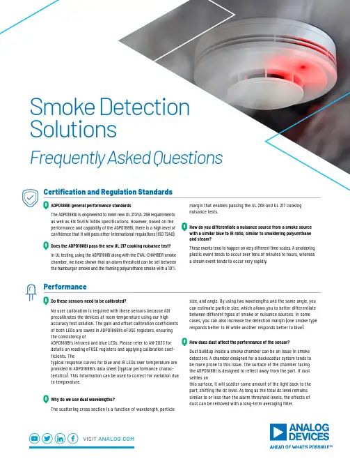
performance and capability of the ADPD188BI, there is a high level of confidence that it will pass other international regulations (ISO 7240).Does the ADPD188BI pass the new UL 217 cooking nuisance test?In UL testing, using the ADPD188BI along with the EVAL-CHAMBER smoke chamber, we have shown that an alarm threshold can be set between the hamburger smoke and the flaming polyurethane smoke with a 10%How do you differentiate a nuisance source from a smoke source with a similar blue to IR ratio, similar to smoldering polyurethaneand steam?These events tend to happen on very different time scales. A smoldering plastic event tends to occur over tens of minutes to hours, whereas a steam event tends to occur very rapidly.Q QDo these sensors need to be calibrated?No user calibration is required with these sensors because ADIprecalibrates the devices at room temperature using our highaccuracy test solution. The gain and offset calibration coefficients of both LEDs are saved in ADPD188BI’s eFUSE registers, ensuring the consistency ofADPD188BI’s infrared and blue LEDs. Please refer to AN-2033 for details on reading eFUSE registers and applying calibration coef-ficients. Thetypical response curves for blue and IR LEDs over temperature are provided in ADPD188BI’s data sheet (typical performance charac-teristics ). This information can be used to correct for variation due to temperature.Why do we use dual wavelengths?The scattering cross section is a function of wavelength, particlesize, and angle. By using two wavelengths and the same angle, you can estimate particle size, which allows you to better differentiate between different types of smoke or nuisance sources. In some cases, you can also increase the detection margin (one smoke type responds better to IR while another responds better to blue ).How does dust affect the performance of the sensor?Dust buildup inside a smoke chamber can be an issue in smoke detectors. A chamber designed for a backscatter system tends to be more prone to this issue. The surface of the chamber facing the ADPD188BI is designed to reflect away from the part. If dust settles onthis surface, it will scatter some amount of the light back to the part, shifting the dc level. As long as the total dc level remains similar to or less than the alarm threshold levels, the effects of dust can be removed with a long-term averaging filter.Q Q Q PerformanceVISIT Smoke Detection SolutionsFrequently Asked QuestionsIs forward scattering more efficient than the ADPD188BI scattering method?The forward scattering event itself is more efficient. However, more light is lost due to the larger distances involved in a forward scattering system. The net effect is that the total efficiency is similar.Why does the dc background level need to be smaller or similar to the alarm threshold level?A larger background level will magnify the effects of any changes in the system, such as vibration and temperature. If the background level is significantly larger than the alarm threshold level, these other effects can cause significant shifts in the performance of the device or require additional algorithmic work.How are smoke response results presented?The smoke response for the blue and IR channels of the ADPD188BI is demonstrated by the power transfer ratio (PTR) in units of nW of optical power returned to the photodiode per mW of optical power emitted by the LED. Presenting results with PTR allows a meaningful comparison of different types of smoke. The conversion from PTR to actual code counts expected from the system is a function of the specific AFE settings, including gain, number of pulses, and LED current.QQ QPrinciple of OperationDo we need a new smoke chamber design?Yes. The smoke chamber needs to be designed such that the dc level is similar to or less than the alarm threshold levels. An ADPD188BI-based system is more sensitive to material directly above the sensor (because of the orientation of the optics) than a forward scatter system and, in almost all designs, a dc level will be present. This dc level can also be used in a full self-test of the alarm and to assist in observing the long-term drift of the device. ADI has designed a new patented smoke chamber that is optimized to work with the ADPD188BI. There are two evaluation models available: EVAL-CHAMBER (two pieces) and EVAL-CHAMBER-10 (10 pieces). The production version is the Accumold 28800X and is available from Accumold and Arrow. Alternatively, please contact ADI if interested in licensing this design.What size is the ADI chamber?The chamber is 30 mm × 36 mm × 11.4 mm.Can we build a smoke detector without a chamber?Yes, but there are two major challenges in building a chamberless system: ambient light and separating proximity from smoke events. The ADPD188BI has excellent ambient light rejection, and designs have been demonstrated that can pass the EN dazzle test. And proximity events (a person walking underneath the detector) can be separated from a smoke event by looking at the ratio change in the two colors.How can I manage for the ingress of dust and bugs onthe solution?A high-pass filter can be applied to manage the issue and remove the background noise from the chamber. To keep the chamber clear of bugs and other obstructions, a bug net or mesh can be added.Q Q Q QChamber and Optical DesignWhat operational conditions/limitations have been tested for the CN-0537 reference design?The CN-0537 reference design is tested against what’s specified in UL 217 for temperature and humidity.Lifetime is not a test that was run, as the estimated lifetime will change based on how customers plan to use their device in their application.Assuming nominal operation at 38°C, our burn-in data shows that LED light degradation after long-term use is <20%. UL 217 specifies that light degradation must be <50%. The ADPD188BI was subjected to multiple burn-in stresses for >1000 hours with higher than typical settings as per the data sheet. This provided burn-in data, which is used to calculate acceleration factors, on the photodiode, LED, and ASIC subcomponents. These acceleration factors, when applied for a 38°C use case, show a predicted lifetime up to 20 years with normal operation.What are the best practices for layout?The EVAL-ADPD188BIZ-S2 evaluation board is designed to be used with the EVAL-CHAMBER smoke chamber. The smoke chamber helps control the environment around the ADPD188BI module. The EVAL-CHAMBER smoke chamber is attached to the EVAL-ADPD188BIZ-S2 evaluation board with rivets or self-tapping screws. Figure 1 (page 4) shows the smoke chamber attached to the evaluation board using rivets.For optimal smoke detection, ensure that the chamber is perfectly centered over the ADPD188BI sensor. This is achieved by placing the chamber over the marked white circle on the eval board.To limit interference, ensure that the digital lines are kept away from the power supply, as this will decrease power interruption. Additionally, when utilizing external inputs on the eval board, keep connections away from the digital components for best practices. Follow general best practices for grounding and decoupling capacitors.What is the MTTF?MTTF refers to mean time to failure, which is the mean time it takes for a first failure to occur under specified operating conditions. It is calculated by dividing the total number of device operating hours by the number of failures. Details of the ADPD188BI MTTF can be obtained at /reliabilitydata.QQ QQuality and Reliability 2SMOke DeTeCTION SOLuTIONSSolution Options Description IncludesHardware EVAL-CN0537-ARDZ EVAL-ADICUP3029Smoke detector reference design hardware for prototypingand solution evaluation. A tested and verified UL 217 smokedetection algorithm is embedded as part of the installerfor evaluation.Hardware►Smoke detector (CN-0537) reference design►Microcontroller development board (ADICUP3029)Software►UL 217 embedded SW executable (.hex)►ADPD188BI no-OS driverDocumentation►CN-0537 circuit note►CN-0537 hardware user guide►Tested and verified UL 217 test resultData EVAL-CN0537-DATA The CN-0537 source code (excluding the detection algorithm)provides an extensive smoke dataset taken at UL 217 certifiedfacilities for those who wish to develop their own algorithm.Data►UL 217 test datasets filesSoftware►CN-0537 source code (excl. detection algorithm)Documentation►UL 217 test datasets user guideAlgorithm EVAL-CN0537-ALGO The algorithm (EVAL-CN0537-ALGO) package includes everythingin the data package and a UL certified smoke detectionalgorithm with associated algorithm project files.This includes the full source code and a UL 217 8th edition testedand verified algorithm, associated project files, CN-0537 sourcecode, and 1000+ sample fire/smoke datasets to acceleratesystem development.Software►CN-0537 source code including UL 217 8th ed. detection algorithm (.c)►MATLAB® and Python UL 217 algorithm projectsData►UL 217 test datasets filesDocumentation►UL 217 algorithm documentation►UL 217 test datasets user guide►MATLAB/Python user guideSupport►10 hours of phone supportDoes ADI provide software assistance or algorithms?Yes. ADI has a complete smoke detection reference design (CN-0537) plus software and algorithm that is tested to meet the UL 217 8th edition smoke/fire detection standards. To address the needs of different customers, a number of solution offerings are available, which are summarized in the table below.What are the processing recommendations or requirements?At a minimum, the microcontroller should be a 32-bit Arm® Cortex®-M0 (or equivalent) with 128 kB of Flash and 16 kB SRAM, and have either an SPI or I2C peripheral.Does the CN-0537 require temperature compensation?The ADPD188BI smoke sensor requires temperature compensation. The CN-0537 has an on-board temperature sensor inside the chamber to measure the temperature, and the software compensates for that.QQ QAlgorithm and SoftwareVISIT /SMOkeDeTeCTION3What additional evaluation resources are available?EVAL-ADSMOKEKITZ is a comprehensive out-of-the-box smoke evaluation kit for high accuracy, integrated smoke detection monitoring. It provides users with all the necessary components to get up and running quickly with designing their custom smoke detection product, including the WaveTool graphical user interface (GUI ). Are samples available?An evaluation board is included in the EVAL-ADSMOKEKITZ Smoke Evaluation Kit. The board (model EVAL-ADPD188BIZ-S2) is available for purchase from the ADPD188BI product page at /eval-adpd188biz-s2.Samples are also available at: /samples_purchase .What other resources are available?For the latest list of available resources, see the Smoke Detection andADPD188BI pages at /smokedetection and /adpd188bi .Other questions/feedbackADI values feedback on our smoke sensing solutions. Please send questions or feedback to ADI via our online community at /optical_sensing .Q QQ Q Additional Design ResourcesKit ComponentsFigure 1. Evaluation board attached to chamber, top view.VISIT For regional headquarters, sales, and distributors or to contact customer service and technical support, visit /contact .Ask our ADI technology experts tough questions, browse FAQs, or join a conversation at the engineerZone Online Support Community. Visit .©2020 Analog Devices, Inc. All rights reserved. Trademarks and registered trademarks are the property of their respective owners.BR22652-12/20。

专利名称:一种自供电偏振可见光探测器及制备方法与应用专利类型:发明专利
发明人:李国强,陈胜,王文樑,柴吉星
申请号:CN202111151502.0
申请日:20210929
公开号:CN113972298A
公开日:
20220125
专利内容由知识产权出版社提供
摘要:本发明公开了一种自供电偏振可见光探测器及制备方法与应用,所述自供电偏振可见光探测器包括从下到上依次排布的衬底、缓冲层、功能层、SiO2隔离层和金属电极层,其中:缓冲层为从下到上依次排布的AlN层、AlGaN层和GaN层;功能层包括InGaN层、石墨烯层和GeS2层,石墨烯层作为GeS2层和InGaN层之间的电子传输层;SiO2隔离层在InGaN层上;金属电极层分别在GeS2层和InGaN层上。
本发明通过在InGaN层上转移石墨烯并磁控溅射沉积GeS2薄膜形成异质复合薄膜,可以有效提高可见光探测性能,在提高器件的光电流与响应度的同时,能有效限制器件的暗电流与噪声,实现偏振选择探测。
申请人:华南理工大学
地址:510640 广东省广州市天河区五山路381号
国籍:CN
代理机构:广州市华学知识产权代理有限公司
代理人:李君
更多信息请下载全文后查看。
可控制红外发射率的电致变色器件
岳桢干
【期刊名称】《红外》
【年(卷),期】2009(30)10
【摘要】据www.defensetechbrief.com网站报道,作为大力发展红外自适应伪装技术的一部分,美国陆军研究管理处在研究中开发了一些红外发射率可调的电致变色器件。
凡是人们想用伪装技术来隐藏的物休,它们的温度通常都高于其周围的环境温度,因此红外自适应伪装技术的基本理念就是以可控制的量来减小目标物体的红外发射率,以致从红外摄像机里看起来,目标物体已与背景混为一体。
【总页数】1页(P6-6)
【关键词】红外发射率;电致变色器件;控制;伪装技术;环境温度;红外摄像机;.com;美国陆军
【作者】岳桢干
【作者单位】
【正文语种】中文
【中图分类】TP3;TK122
【相关文献】
1.可变发射率器件中WO3电致变色研究进展 [J], 李德柱;董亮;王豫
2.电致变色红外可调谐滤光片和发射率调制器 [J], 高(编译)
3.电沉积聚苯胺薄膜在离子液体BmimPF6中的电致变色响应及电致变色器件研究
[J], 张欣妍;孙洁;郭善良;秦军荣;厉孝广;张盛夏;王荣
4.电致变色聚噻吩及其固态电致变色器件的制备 [J], 刘平;王娟;关丽;腊明;蒋传煜;童真;邓文基
5.电致红外发射率动态调控器件研究进展 [J], 程柏璋;祝玉林;伊洋;陶鑫;贾岩;刘东青;程海峰
因版权原因,仅展示原文概要,查看原文内容请购买。