德国UWT料位开关产品介绍
- 格式:ppt
- 大小:6.47 MB
- 文档页数:28
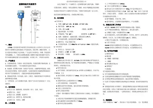
射频导纳开关说明书(L2000)一、概述L-2000系列射频导纳物位控制器是我公司科研人员在总结国内外大量物位仪表的基础上开发成功的,其技术性、测量可靠性,已在大量应用中得到了充分体现。
广泛适用于各类料仓、容器、管道的料空料满测量,上、下限自动报警或检测。
报警时可输出继电器开关信号,经中间继电器或直接与启动设备连锁,可实现上料、下料的自动控制。
二、产品特点1. 安装调试简易:全密封一体化安装结构,全部采用数字集成电路,无任何机械可动部件。
一经安装校零无需多次调试。
2. 低温漂:采用数字电器,与现有产品比较,大幅降低环境温度、湿度对仪表进行的影响,换季无需调零。
先进的电路设计能避免物料粘附在探头所产生的虚假信号,又能抗各种波动所造成的影响。
3. 现场适应性强:可在高温、高压、大粉尘、高粘度的场合中对固体及液体物料进行检测。
4.一次性校零:由于采用数字电路,使用户可以在空仓的状态下一次完成校零。
三、适用领域a)电力工业:输煤系统、除灰系统(灰斗、仓泵、灰库)b)建筑工业:水泥厂c)食品工业:面粉罐、包装料斗d)制药工业:原料贮仓、配料混合罐e)造纸工业:木屑仓、液罐四、工作原理由电子线路产生一个高频信号,送至测量电极与保护电极,当物料位置改变时,就把这一变化反馈给电子线路,而电子线路通过容抗和阻抗的综合变化信号与基准信号作比较,当两信号相差达到一定大小时,就改变继电器的输出状态,从而指示物位变化。
五、技术参数a)控制部分1. 电源:220V AC±10%,50/60HZ;24V DC±10%;2. 触点容量: 250V AC 5A;3. 功耗:最大2.5W;灵敏度:≤0.3PF;4. 输出继电器:单刀双掷;5. 环境温度:-40~65℃;温度影响:0.3PF/30℃;6. 校准:按键校零灵敏度设置:设置范围为1-9档;7. 开关延时设置:延时值范围为0-59秒;8.报警形式:可选上限或下限;9:外壳防护标准:符合NEMAI-5.4X和12&13(IP65)的防护标准。
uwt重锤料位计说明书UWT重锤料位计是一种先进的工业自动化装置,用于测量物料的高度或容器中物料的体积。
它采用了全新的测量原理,能够准确、稳定地获取物料的实时数据。
本篇文章将全面介绍UWT重锤料位计的特点、工作原理、安装步骤以及使用注意事项,希望能为广大用户提供有益的指导。
UWT重锤料位计的特点如下:1. 高精度:UWT重锤料位计采用先进的传感技术,具有高精度的测量能力,能够实时准确地检测物料的高度或容器中物料的体积。
2. 稳定可靠:UWT重锤料位计具有良好的稳定性和可靠性,能够在各种复杂的工业环境下正常工作,保证数据的准确性和可靠性。
3. 高效节能:UWT重锤料位计采用先进的能源管理技术,能够有效节约能源,并提高生产效率,降低生产成本。
4. 灵活多样:UWT重锤料位计可根据用户的需求进行定制化设计,适用于各种不同的物料和容器类型,满足不同行业的测量要求。
UWT重锤料位计的工作原理:UWT重锤料位计采用重锤的原理进行物料高度或体积的测量。
它通过连接在重锤上的传感器,实时检测重锤的位置变化,从而获取物料的高度或体积。
在测量过程中,重锤被悬挂在容器内,并随着物料的堆积而上升或下降。
传感器会实时感知重锤的位置变化,并将数据传输给控制系统。
控制系统将数据进行处理,并通过显示屏或计算机界面等形式展示给用户。
UWT重锤料位计的安装步骤:1. 选择合适的安装位置:在安装UWT重锤料位计之前,首先需要选择一个合适的位置。
该位置需要尽可能接近物料的堆积区域,以保证测量的准确性。
2. 安装传感器:根据厂家提供的安装说明,将传感器固定在容器上方,并与重锤连接。
同时,需要确保传感器与重锤之间的连接牢固可靠。
3. 连接电源和信号线:将UWT重锤料位计的电源线和信号线连接到控制系统或显示屏上。
在连接过程中,需要注意电气设备的安全操作规范。
4. 调试和测试:完成安装后,进行调试和测试。
确保UWT重锤料位计正常工作,能够准确测量物料的高度或容器中物料的体积。
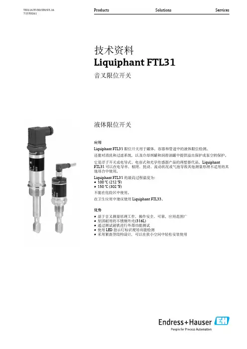
液体限位开关应用Liquiphant FTL31限位开关用于罐体、容器和管道中的液体限位检测。
还能对清洗和过滤系统,以及冷却剂罐和润滑油罐中提供溢出保护或泵空转保护。
它是浮子开关或电导式、电容式和光学传感器产品的理想替代品。
LiquiphantFTL31可以在电导率、粘附、扰动、流动状况或气泡导致其他测量原理不适用的其他场合中使用。
Liquiphant FTL31的最高过程温度为:•100 °C (212 °F)•150 °C (302 °F)不能在危险区中使用。
在卫生应用中建议使用Liquiphant FTL33。
优势•基于音叉测量原理工作,操作安全、可靠,应用范围广•坚固耐用的不锈钢外壳(316L)•通过测试磁铁进行外部功能测试•使用LED 指示灯标识现场功能检测•采用紧凑型结构设计,可以在狭小空间中轻松安装使用Products Solutions Services技术资料Liquiphant FTL31音叉限位开关TI01147F/00/ZH/03.1671330261Liquiphant FTL312Endress+Hauser目录文档信息 (3)文档符号 (3)功能与系统设计 (4)测量原理...................................4测量系统.. (4)输入 (5)测量变量...................................5测量范围.. (5)输出 (5)开关量输出.................................5工作模式.. (5)电源 (5)供电电压...................................5功率消耗...................................5电流消耗...................................5残余波动电压................................5电气连接...................................5电缆入口...................................9电缆规格..................................10过电压保护.. (10)性能参数 (11)参考操作条件...............................11开关点...................................11迟滞性...................................11重复性...................................11环境温度的影响.............................11介质温度的影响.............................11介质压力的影响.............................11开关切换延迟时间...........................11开启时间..................................11工作频率..................................11测量误差..................................11安装条件 (12)安装方向..................................12安装指南..................................12连接电缆长度. (14)环境条件 (15)环境温度范围...............................15储存温度..................................15气候等级..................................15海拔高度..................................15防护等级..................................16抗冲击性..................................16抗振性...................................16电磁兼容性(EMC)............................16极性反接保护...............................16短路保护 .................................16过程条件 (17)过程温度范围...............................17过程压力范围...............................17密度.....................................17聚集状态..................................17粘度.....................................17含固量...................................17横向负载能力...............................17机械结构 (18)设计.....................................18连接头...................................19叉体.....................................19传感器类型................................20重量.....................................23材料.....................................23表面光洁度................................24可操作性 (25)LED 指示灯................................25通过测试磁铁进行功能测试.....................25证书和认证 (26)CE 认证...................................26EAC 一致性声明.............................26RCM-Tick 认证..............................26认证.....................................26溢出保护..................................26船级认证..................................26CRN 认证..................................26检测证书..................................26制造商声明................................26压力设备指规程.............................26其他标准和准则.............................26订购信息 (27)订购信息..................................27服务(可选) (27)附件 (27)焊座.....................................27插座,电缆................................27其他附件. (28)补充文档资料 (29)《操作手册》...............................29其他文档资料...............................29证书. (29)Liquiphant FTL31文档信息文档符号安全图标电气图标特定信息图标图中的图标Endress+Hauser3Liquiphant FTL314Endress+Hauser功能与系统设计测量原理在压电晶体驱动下,Liquiphant FTL31的叉体以共振频率振动。
SUN-T系列无源核子料位计上海沃纳机电科技有限公司1、产品原理 ——————— 第2页2、产品特点 ——————— 第3页3、产品介绍 ——————— 第4页4、电厂运用 ——————— 第8页5、产品安装 ——————— 第10页6、调控系统 ——————— 第11页8、产品比较 ——————— 第12页9、公司简介 ——————— 第13页SUN-T 系列 小型 增强功能 无源核子料位计γ射线, 是指波长 1pm—10 pm 的电磁波 ;x 射线,是指波长在1nm—10 nm 的电磁波。
他们是高能量的光子流、电磁波,都是高能射线。
原子在两种状态下会向外释放射线:1、原子核内激发。
当放射性物质的原子核发生α衰变或β衰变时,原子核处在激发态。
而当原子核由激发态跃迁到基态时,会放出高能光子、释放出γ射线、x 射线。
2、原子核外内层电子激发。
当物质的原子受到外部能量激发时,围绕原子核的内层电子会从低能级轨道跃迁到高能级轨道。
而这样的激态电子运动是不稳定的,当它重新回到低基态时,就会以x 射线形式将能量释放出来。
激发方式有剧烈燃烧、高能光子流、电子流轰击等。
高能射线有很强的穿透力,在穿过物质时,强度减弱与物质的密度相关,符合指数规律。
主要机理是一定能量的射线束中的光子与物质发生光电效应、康普顿效应和电子对效应后损失其能量,从原射线束中消失。
光电效应 康普顿效应 电子对效应强度为I 0的射线穿过厚度为t ,密度为ρ的被测物后,强度减为I ,当I 0和t 一定时,I 与ρ相关。
I = I 0e -tρk其中k 为质量吸收系数有源核子料位计的原理是利用人工处理的137Cs、60Co 等放射性物质作为放射源。
γ射线是由物质衰变时放射出的,放射性强度非常高。
其测量是一种主动测量。
当物料达到放射源所在位置时,射线受到物料阻挡与吸收。
接受器根据射线强度的变化,判断物料是否达到测量位置。
无源核子料位计的原理是一种被动测量仪器,不需要人工放射源,充分利用自然环境中广泛存在的微量天然放射性核素所释放的γ射线、X 射线,以及剧烈燃烧、强光子轰击等激发条件下,所释放的X 射线。
*****************6号楼2单元1207室315号中泰国际广场6号楼818室27号商鼎国际2栋一单元1310室809室石家庄办事处地 址:河北省石家庄市长安区方北路58号剑桥春雨1号楼1107室武汉办事处地 址:湖北省武汉市武昌区武珞路中南国际城二期B1-1602室电话:181****2680,181****5276沈阳办事处地 址:沈阳市铁西区云峰北街33号巴塞罗那晶座6号楼2单元3001室广西办事处地 址: 广西南宁市西乡塘区明秀西路118号百汇华庭A单元7楼郑州办事处地 址:郑州市中原区建设路鑫苑国际广场A座15层1503室优质稳定——打造优秀的控制系统产品Excellent Automation System Help U WinUW2100工业物联网控制系统eDCS系统手册电 话:*************传 真:*************邮 编: 310030公司网址:技术中心:浙江大学控制工程国家实验室大楼 生产基地:杭州市西湖科技园西园路1号目 录UW2100工业物联网控制系统eDCS产品手册企业简介公司简介发展历程资质荣誉产品概述系统概述技术特点系统架构硬件选型软件平台解决方案【楼宇】UW智慧楼宇解决方案【节能】UW建筑能耗监控解决方案【管廊】UW智慧管廊解决方案【交通】UW智慧隧道物联网监控解决方案【热网】UW供热管网监控解决方案【锅炉】UW锅炉物联网监控解决方案【环保】UW环境物联网监控解决方案【环保】UW公用工程物联网监控解决方案【安监】UW危险源物联网监控解决方案【装备】UW智能工业装备物联网解决方案典型客户服务支持2468810111622263035363840424445杭州优稳自动化系统有限公司与浙江大学工业自动化国家工程研究中心建立联合技术中心,形成自主知识产权的控制系统技术体系,具有领先的创新意识和丰富的技术资源;公司业务范围涉及智能仪表、可编程控制器、集散控制系统、安全控制系统、控制工程应用软件平台的研究开发、生产制造与工程服务;公司创立“UWNTEK”产品品牌与“优稳自动化”公司品牌;获国家高新技术企业、国家863重点项目参与单位、国家创新基金支持企业、浙江省软件企业、浙江省工业自动化创新服务平台、浙江省企业技术中心、杭州市首批科技型中小企业、杭州市首批雏鹰企业、杭州市企业技术中心、杭州市大学生见习基地、ISO9001:2008质量管理体系认证等企业资质;公司坚持“优质稳定、共赢分享”的经营理念,用优质稳定的控制系统产品为客户、伙伴、员工、股东及社会创造价值:UWNTEK —— Excellent Automation Control System help U Win公司以“打造最优秀的自动化系统产品,成为工业自动化领域领先的产品供应商”为经营目标,专业专注于新一代控制技术的产业化与服务;自主设计开发完成全系列控制系统硬件模块与软件平台,各型控制系统产品已广泛应用于化工、制药、炼油、石化、钢铁、能源、建材、轻工、造纸、环保等行业5000余套,控制器应用约20000余套。
微型料位开关全文共四篇示例,供读者参考第一篇示例:微型料位开关是一种用于检测和监控物料水平的设备,其小巧轻便的设计使其非常适合安装在狭小空间或者对装载有限的设备上。
这种开关通常由功能性部件和外壳组成,通过不同的工作原理来实现物料水平的检测。
它们被广泛应用于各种工业领域,如食品加工、化工、医药等,起到了非常重要的作用。
微型料位开关的种类繁多,主要可以分为浮球式、振动式、电容式等几类。
浮球式料位开关通过浮球的上升和下降来开关触点,当物料水位达到一定高度时,浮球会浮在物料表面,从而使开关触点闭合;而当物料下降到一定程度时,浮球则会沉下来,开关触点则会断开。
这种操作原理简单易懂,且结构稳定,因此在许多行业得到广泛运用。
振动式料位开关则是通过探头上的振动部件来实现物料水位的检测,当物料达到一定高度时,会阻碍振动部件的振动,触发开关动作;反之,在低水位时则不会有阻碍振动的物料存在,保持开关处于关闭状态。
这种类型的料位开关由于设计简洁、敏感度高、不易受外界干扰,因此被广泛应用于粉体、颗粒物料的检测领域。
电容式料位开关通过物料和电容传感器之间的介电常数差异来实现开关触点的动作。
当物料接触到电容传感器时,会改变电容传感器感应的电容值,从而触发开关的动作。
这种类型的料位开关具有精确的检测能力,可以应用于各种不同介电常数的物料,具有较强的通用性和灵活性。
微型料位开关在工业领域有着广泛的应用,可以用于物料的控制、监测和报警。
在食品加工行业,微型料位开关可以用于监测食品的水平,确保生产过程的顺利进行,同时也可以用于检测食品的残留物料,保障产品质量。
在化工行业,微型料位开关可以用于监测化工原料的储存和消耗情况,及时控制生产过程,确保生产安全。
在医药行业,微型料位开关可以用于监测药品的存储情况,精准控制药品的配料比例,保障产品质量。
虽然微型料位开关在工业领域有着广泛应用,但是在选择和安装时仍需注意一些问题。
需要根据物料的特性来选择适合的料位开关类型,确保其可以正确地检测物料水平。
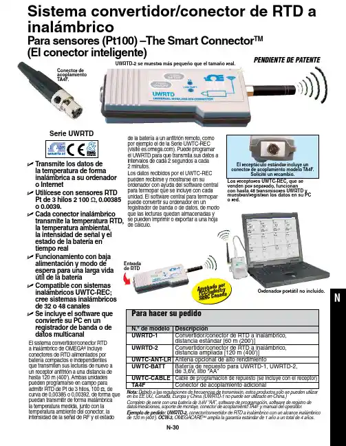
N-30N U T ransmite los datos de la temperatura de forma inalámbrica a su ordenador o Internet U U tilícese con sensores RTD Pt de 3 hilos 2 100 Ω, 0.00385 o 0.0039.U C ada conector inalámbrico transmite la temperatura RTD, la temperatura ambiental, la intensidad de señal y el estado de la batería en tiempo realU F uncionamiento con baja alimentación y modo de espera para una larga vida útil de la bateríaU C ompatible con sistemas inalámbricos UWTC-REC; cree sistemas inalámbricos de 32 o 48 canalesU S e incluye el software que convierte su PC en un registrador de banda o de datos multicanal El receptáculo estándar incluye unPENDIENTE DE PATENTEde la batería a un anfitrión remoto, como por ejemplo el de la Serie UWTC-REC (visite ). Puede programar el UWRTD para que transmita sus datos a intervalos de cada 2 segundos a cada 2 minutos.Los datos recibidos por el UWTC-REC pueden recibirse y mostrarse en su ordenador con ayuda del software centralpara termopar que se incluye con cada unidad. El software central para termopar puede convertir su ordenador en un registrador de banda o de datos, de modo que las lecturas quedan almacenadas yse pueden imprimir o exportar a una hoja de cálculo.El sistema convertidor/conector RTD a inalámbrico de OMEGA ® incluye conectores de RTD alimentados por batería compactos e independientes que transmiten sus lecturas de nuevo a un receptor anfitrión a una distancia de hasta 120 m (400'). Ambas unidades pueden programarse en campo para admitir RTD de Pt de 3 hilos, 100 Ω, de curva de 0,00385 o 0,00392, de forma que puedan transmitir de forma inalámbrica la temperatura medida, junto con la temperatura ambiente del conector, la intensidad de la señal de RF y el estadoen los EE.UU., Canadá, Europa y China. (UWRTD-1 no puede ser utilizado en China.)Completo de serie con una batería de 3,6V “AA”, software de programación, software de registro dedatos/mediciones, soporte de montaje, conector de acoplamiento T A4F y manual del operador.Ejemplo de pedido: UWRTD-2, conector/convertidor de RTD a inalámbrico con un alcance inalámbrico de 120 m (400'). OCW-3, OMEGACARE SM amplía la garantía estándar de 1 año a un total de 4 años.venden por separado, funcionan con hasta 48 transmisores UWRTD y muestran/registran los datos en su PC o red.Entrada de RTD Conector de acoplamiento TA4F.A p r o b a d o p o r F C C /I n d u s t r y S R R C C a n a d a Ordenador portátil no incluido.Serie UWRTD UWRTD-2 se muestra más pequeño que el tamaño real.Sistema convertidor/conector de RTD a inalámbrico Para sensores (Pt100) –The Smart Connector TM (El conector inteligente)。
DELLSONICS北京迪妙声科技有限公司BEJING DELLSONICS SCIENCE & TECHNOLOGY LTD.公 司 简 介北京迪妙声科技有限公司(原名北京妙声力科技有限公司),位于北京市海淀区中关村南大街,是与西门子公司德国总部正式签约的西门子过程仪表及分析仪器核心合作伙伴,也是西门子北方区域规模最大、实力最强的优秀代理商。
公司主营:一、西门子-妙声力(Milltronics)系列物位产品:超声波物位计、超声波液位差计、超声波泥水界面计、超声波明渠流量计、雷达物位计、射频导纳物位计、射频导纳油水界面计、;射频导纳物位开关、音叉式物位开关、阻旋式物位开关;皮带称、固体质量流量计、冲板流量计等。
二、西门子过程仪表产品:电磁流量计、质量流量计、超声波流量计、 温度变送器、压力变送器、阀门定位器、气体分析仪等。
三、德国UWT公司的阻旋式料位开关、音叉式料位开关、重锤式料位计等产品。
四、自行研发生产超声波液位计、温度变送器、压力变送器、数显表及油田专用仪器等产品。
成立于 1954 年的西门子-妙声力公司(Milltronics)是世界公认的超声波物位测量领域的领导者,全球最大的超声波物位仪表生产厂家,在超声波、雷达、电容技术领域拥有超过 60 项专利,超声波产品的综合性能指标经美国《控制》杂志评比,其综合性能名列全球第一!作为西门子公司长期稳定的代理商,我公司有着10 余年产品的销售和服务经验,无论从专业技术水平、现货及备件库存量、售后服务质量、仪表维护以及故障产品国内维修能力等方面,都具备显著的优势。
尤其是我公司一流的技术支持和高效率高品质的服务体系,在业界具有很高的知名度。
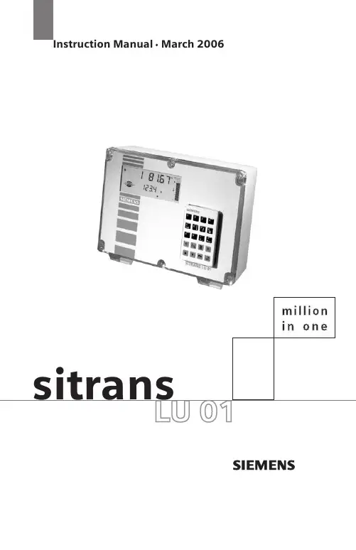
如果您需要相关的产品,需要咨询技术问题,需要值得信赖的合作伙伴,敬请来电垂询!传真:总机转50谢谢您的合作与支持!Table of ContentsIntroduction (1)SITRANS LU 01 (1)SITRANS LU 01 Features (3)Programmable Features (3)The Manual (4)Specifications (5)Electronics (5)Programmer (6)Transducer (7)Options (7)Cable (7)Safety marking symbols (8)Installation (9)SITRANS LU 01 (9)Location (9)Cable/Conduit Entry Requirements (9)Mounting (10)Transducer Mounting (10)Interconnection (11)Optional SmartLinx Module (13)System Diagram (14)Transducer (14)Temperature Sensor (15)Relays (15)mA Outputs (15)Communication (16)Serial (16)SmartLinx (16)Level System Synchronization (16)Power (17)AC Supply Wiring (17)DC Supply Wiring (17)Programmer (18)Communications Access (18)Programming (19)Display (19)Keypad (20)Program Mode Entry (21)Changing Parameters (21)Parameter Reset Features (22)Parameters Types (22)Programming Security (22)Operation (23)Display in RUN Mode (23)Keypad (24)System Performance Evaluation (25)Performance Test Results (25)Parameter Reference (27)Helpful Hints (27)Parameter Reset Features (28)Programming Security (28)Quick Start (P001 to P007) (29)Application Parameters (32)Volume (P050 to P055) (32)Display and Reading (P060 to P062) (36)Failsafe (P070 to P072) (37)Relays (P100 to P119) (39)Custom Relays (P111 to P113) (42)Independent Relay Setpoints (43)Independent Relay Failsafe (P129) (46)mA Output (P200 to P219) (47)Independent mA Setpoints (P210 and P211) (48)mA Output Limits (P212 and P213) (48)mA Output Trim (P214 to P215) (49)mA Output Failsafe (P219) (50)Standard Data Logging (P300 to P321) (50)Record Temperatures (P300 to P303) (50)Profile Records (P330 to P337) (51)Auto Record ON and OFF Setpoints (P334 to P337) (52)Installation Records (P340 to P342) (54)Range Calibration (P650 to P654) (54)Temperature Compensation (P660 to P664) (57)Rate (P700 to P707) (58)Measurement Verification (P710 to P713) (60)Transducer Scanning (P725 to P729) (62)Display (P730 to P733) (63)Peripheral Communication Support Parameters (P740 to P749) (65)SmartLinx Reserved (750 to 769) (65)Communications (P772) (66)SmartLinx Hardware Testing (66)Echo Processing (P800 to P807) (67)Advanced Echo Processing (P810 to P825) (70)Profile Pointer (P817 to P825) (72)Advanced TVT Adjustment (P830 to P835) (75)Advanced Shot Adjustment (P840 to P852) (78)Test (P900 to P913) (80)Measurement (P920 to P927) (83)Technical Reference (85)Transmit Pulse (85)Echo Processing (85)Echo Processing Displays (Scope Displays, P810) (86)Dolphin Plus Display (86)Distance Calculation (86)Sound Velocity (86)Volume Calculation (87)Universal, Linear (P050 = 9) (87)Universal, Curved (P050 = 10) (88)Maximum Process Speed (88)Application Examples (89)Example 1 - Level Measurement (90)Material Volume (92)Example 2 - Space Measurement (92)Application Assistance (94)Communication Support (94)MT-00 Measurement Message (95)MT-01 Hold Message (96)MT-03 Point Not Scanned (97)Maintenance (98)Unit Repair and Excluded Liability (98)Troubleshooting Guide (99)Measurement Difficulties (100)Flashing LOE Display (100)Fixed Reading (101)Wrong Reading (102)Programming Charts (104)IntroductionSITRANS LU 01Note: The SITRANS LU 01 is to be used only in the manner outlined in thisinstruction manual.The SITRANS LU 01 is an ultrasonic long-range level monitoring system for liquids and solids. SITRANS LU 01 level monitor uses one Siemens Milltronics ultrasonic transducers (ordered separately) to accurately monitor material levels without material contact.The SITRANS LU 01 transmits electronic pulses to each connected ultrasonic transducer.The transducer converts the electronic pulses to ultrasonic pulses which are emitted from the transducer face in a narrow beam. The SITRANS LU 01 measures the time from the pulse emission, to reception of the reflection (echo) from the material. Using the time measured, the SITRANS LU 01 calculates the distance from the transducer face to the material.The distance calculation depends upon the sound velocity within the vessel. When an Echomax transducer is used, variable air temperatures are automatically compensated.For superior air temperature compensation, a Siemens Milltronics TS-3 temperaturesensor may be used for each vessel. A simple calibration feature compensates forThe SITRANS LU 01 uses Siemens Milltronics patented Sonic Intelligence®echoprocessing. Sonic Intelligence provides high measurement reliability, regardless ofchanging conditions within the vessel monitored. By using ultrasonic echo rangingprinciples with Sonic Intelligence and velocity compensation, the SITRANS LU 01provides outstanding measurement accuracy, usually within 0.25% of range.The distance calculation can be converted to space, material level, material volume, or remaining vessel capacity. The reading chosen (and operating data) for each vessel is displayed on the LCD (liquid crystal display).The relays and mA outputs may be used as preset (or programmed as desired) to activate alarms and/or operate remote monitoring equipment and/or process control equipment.With the addition of a Siemens Milltronics Smartlinx ® protocol specific plug-in communications module, the SITRANS LU 01 is compatible with popular industrial control system standards. Supported protocol include PROFIBUS DP, Allen-Bradley®1 Remote I/O, Modbus® RTU, and DeviceNet TM.Programming can be done locally using the portable programmer keypad, or remotely through optional Dolphin Plus software or SmartLinx.•The programmer transmits the keypad entries via infrared link to the SITRANS LU 01, and can be removed when not in use.•Dolphin Plus allows programming either through the RJ-11 port or hardwired via the RS-232/485 communication port.•SmartLinx provides protocol specific hardware and software for interface with popular industrial communication systems.1.Allen-Bradley is a registered trademark of Rockwell Automation. Modbus is aregistered trademark of Schneider Electric. DeviceNet is a trademark of ODVA(Open DeviceNet Vendor Association).The SITRANS LU 01 is typically used to monitor material level in open or closed vessels but can be used in almost any process which requires a distance measurement (within the system range).Refer to Technical Reference Application Examples on page89 for detailed descriptions of some configuration examples to which the SITRANS LU 01 may be applied. SITRANS LU 01 Features•Enclosure:Chemical resistant, light weight, dust tight, liquid tight,easy to work with.•Backlit LCD: Large digits for Reading and programming value displays.Illuminated LCD insures readability under all lightingconditions. Includes custom Graphic Symbols for continuousindication of operating conditions.•Programmer:20 tactile feedback keys for easy access to programmingand operating functions. Magnetic mounting and infraredinterface permit removal on programming completion.•Communications:SmartLinx CompatibleCommunications ready when equipped with an appropriateSiemens Milltronics SmartLinx module.•Dolphin Compatible CommunicationsDolphin Plus is Windows®1-compatible configuration softwareconnected to the unit via the RG-11 port or remote connectionthrough the RS-232 or RS-485 port. The software provides aneasy means for programming, uploading,or downloadingparameters.•Speed:16/32 bit microprocessor at 16.7 MHz clock speed. 1 vessel(point) per second scanning speed capability.•Reliability:Sonic Intelligence ensures all measurements are accurateand reliable. Immune to power interruptions. All programmingis stored indefinitely. Dynamic operating data is retained forone hour and updated immediately on power resumption. Programmable FeaturesThe SITRANS LU 01 is easy to program, yet versatile enough to handle complex level measurement requirements.General Features•Direct Access:Any operator programmable feature may be accessed directly.•Scroll Access:Scroll forward, scroll back, to key features.•Operation:Select level, space, or distance operation.•Material:Liquid or solid; automatically adjusts echo processing with oneentry.1.Windows is a registered trademark of Microsoft Corporation.SpecificationsElectronicsPower•AC model:100/115/200/230 V AC ±15%, 50/60 Hz, 31 VA•DC model:18 to 30 V DC, 25 WEnvironmental•location indoor / outdoor•altitude2000 m max•ambient temperature–20 to 50 °C (–5 to 122 °F)•relative humidity suitable for outdoor (Type 4X / NEMA 4X / IP65 enclosure) •installation category II•pollution degree: 4Scan Points• 1 point per SITRANS LU 01 max.•frequency independentRange•Level Measurement:0.3 m (1 ft) to 60 m (200 ft) max.Accuracy•0.25% of range or 6 mm (0.24"), whichever is greaterResolution•0.1% of program range1 or 2 mm (0.08"), whichever is greaterMemory•EEPROM (non-volatile) no back-up battery requiredProgramming•via removable programmer or optional Dolphin Plus softwareDisplay•custom graphics backlit LCD with 51 mm (2 in) x 127 mm (5 in) viewing area Synchronization:•up to 16 SITRANS LU 01 units can be synchronized together Temperature Compensation•–50 to 150 °C (–58 to 302 °F)•integral temperature sensor in transducer•TS-3 temperature sensor•programmable fixed temperatureTemperature Error•with compensation:0.09% of range•fixed temperature:0.17% / °C deviation from programmed temperature.1.program range is defined as the empty distance to the face of the transducer(P006) plus any range extension (P801).Outputs•relays: 4 alarm/control relays1 form "C" SPDT contact per relay, rated 5 A at 250 V AC,non-inductive•analog: 1 output max.0.1% resolution0-20 or 4-20 mA, scalable750 Ω, isolated, 30V rms Communications (see Options)•SmartLinx compatible•RS-232 / 485 port•Dolphin Plus compatible•proprietary bipolar current loopEnclosure•Type 4X / NEMA 4X / IP65 1•285 mm W x 209 mm H x 92 mm D (11.2" W x 8.2" H x 3.6" D)•polycarbonateWeight• 2.7kg(6lb)Approvals•See device nameplate.ProgrammerAmbient Temperature•–20 to 50 °C (–5 to 122 °F)Keypad•20 keys with tactile feedbackInterface•non-invasive, digital, infra-redEnclosure•general purpose•67 mm W x 100 mm H x 25 mm D (2.6" W x 4" H x 1" D)•ABS plasticWeight•150 g (0.3 lb)1. The use of approved watertight hubs/glands is required for Type 4X / NEMA 4X,IP65 on watertight applications.TransducerCompatible Models•STH and Echomax® series•Refer to the associated instruction manual.OptionsTemperature Sensor•TS-3SmartLinx Modules•Supported protocols: PROFIBUS DPAllen-Bradley®1 Remote I/OModbus® RTUDeviceNet TMDolphin Plus•Windows®-compatible configuration software connected to the unit via infraredComverter linkRefer to associated product documentation.CableTransducer•RG-62 A/U (or equivalent), 365 m (1,200 ft) max.See transducer instructions for short extensions (in grounded metal conduit, separate from other wiring)mA Output•Belden 8760, shielded / twisted pair, 18 AWG (0.75 mm2) or equivalent or Belden 9552, shielded / two twisted pair, 18 AWG (0.75 mm2)•maximum separation 1,500 m (5,000 ft)Synchronisation•Belden 8760, shielded / twisted pair, 18 AWG (0.75 mm2) or equivalentRelays•No shielded cable necessaryTemperature sensor•Belden 8760 shielded / twisted pair, 18 AWG (0.75 mm2) or equivalent•365 m (1,200 ft) per TS-3 maximumRJ11 Link•No shielded cable necessary•maximum length 3 m (10 ft)1.Allen-Bradley is a registered trademark of Rockwell Automation. Modbus is aregistered trademark of Schneider Electric. DeviceNet is a trademark of ODVA(Open DeviceNet Vendor Association).RS-232 Link•Belden 8770, 3 conductor/shielded, 18 AWG (0.75 mm2) or equivalent •maximum separation 15 m (50 ft)RS-485 Link•Belden 8770, 3 conductor/shielded, 18 AWG (0.75 mm2) or equivalent •maximum separation 1200 m (4000 ft)SmartLinx module•refer to the associated instruction manual.Safety marking symbolsInstallationInstallation shall only be performed by qualified personnel, and in accordance with local governing regulations.The following procedure applies to all SITRANS LU 01 level monitor installations. See Application Examples on page89 for additional installation requirements. Also, refer to the instruction manuals of all other equipment connected to the SITRANS LU 01 foradditional installation instructions.SITRANS LU 01LocationRecommended•Ambient temperature is always within -20 to 50 °C (-5 to 122 °F)•SITRANS LU 01 display window is at shoulder level, unless most interaction is through a SCADA system•Easy access for hand programmer is provided•Cable length requirements are minimal•Mounting surface is free from vibration•Leave sufficient room to swing unit lid open and have clear access.• A place for a laptop computer is provided for on-site Dolphin Plus configuration Avoid•Exposure to direct sunlight. (Provide a sun shield to avoid direct sunlight.)•Proximity to high voltage/current runs, contacts, SCR or variable frequency motor speed controllersCable/Conduit Entry RequirementsEnclosure cable/conduit entries may be required for:•Transducers•TS-3 temperature sensor (if used)•mA output (if used)•Relays (if used)•Synchronization (see Interconnection/Level System Synchronization)•Power•Communications:SmartLinx, RS-485, RS-232, bipolar.Note: Transducer cables must be run in a grounded metal conduit, separate fromother wiring, (except TS-3 temperature sensor wiring, if applicable).MountingInspect all cartons and packaging for possible damage during shipment, before removing the SITRANS LU 01 and associated equipment.1.Loosen the 6 enclosure lid (captivated) screws and swing the lid open.2.Remove the 4 Board B mounting screws (outer corners) and remove the circuitboard assembly.3.Drill required holes in the enclosure bottom to meet enclosure cable/conduit entryrequirements.4.Attach the enclosure to the selected mounting surface (use four predrilled screwholes).5.Attach the conduits/cable hubs to the enclosure. (Do not apply undue force.)Transducer MountingObjects near the transducer face cannot be reliably detected. Mount the transducer above the highest material level (away from the nearest monitored object) by the following Nearest Distance .Warnings•Non metallic enclosure does not provide grounding between connections. Use grounding type bushings and jumpers.•This product is susceptable to electrostatic shock. Follow proper grounding procedures.Nearest DistanceTransducer Types0.5 m (1.65 ft)11.This is the recommended minimum distance. However, it can be reduced under certain circum-stances. Please check the appropriate transducer manual for details.ST -H, ST -25, XRS-5, XCT-8, XCT-12, XPS-10, XPS-15, ST -500.66 m (2.17 ft)XPS-30, XPS-400.99 m (3.25 ft)ST -100, LR-21, XLT -30, XLS-30 1.32m (4.33 ft)LR-13, XLT-60, XLS-60InstallationInterconnectionBefore interconnecting system components to the SITRANS LU 01 terminals, verify all components have been installed in accordance with the associated product instruction manuals.Connect all associated equipment cable shields to the SITRANS LU 01 shieldconnections. To avoid differential ground potentials, do not connect cable shields to ground (earth) elsewhere. Insulate or tape cable shields at all shield junctions to prevent ground loops.AC ModelDC ModelInstallationOptional SmartLinx ModuleThe standard SITRANS LU 01 unit may also be enhanced with Siemens Milltronics SmartLinx communication modules that provide an interface to popular industrial communication systems.To change or install SmartLinx module:With power off and SITRANS LU 01 lid opened:1.Remove the 4 LCD card screws and the card itself.2.Remove the one dummy card screw and the card itself.3.Mount the card by mating the connectors and secure the card in place using the two screws provided.4.Wire in the SmartLinx card according to SmartLinx Manual.5.Replace the LCD card and secure in place using the screws removed in Step 1.Note: Refer to the SmartLinx module documentation for any required hardwaresettings prior to replacing the LCD card or closing the SITRANS LU 01 lid.System DiagramTransducerNote: Maximum system capability. Not all components or their maximum quantitymay be required.customer devicecustomer alarm, pump or control deviceDolphin Plus, or customer deviceindustry control system such as PLC or DCS,SCADA, etc.Notes:•Transducer cables must be run in a grounded metal conduit separate from other wiring (except TS-3 temperature sensor wiring, if applicable).•Hazardous voltage present ontransducer terminals during operation.InstallationTemperature SensorRelaysmA OutputsNote: Use TS-3 temperature sensor only.Do not jumper the terminals if TS-3 is not used.to TS-3All relays are certified for use in equipment where the short circuit capacity of the circuits in which they are connected is limited by fuses having ratings not exceeding the rating of the relays.Note: relays areshown in de-energized state.See Specifications for ratings.0/4-20mA isolated output to750Ω maxCommunicationSerialSmartLinxRefer to the appropriate SmartLinx manual for installation and wiring.Level System SynchronizationAvoid mounting the SITRANS LU 01 near another ultrasonic level monitor. Likewise, when more than one monitor is installed within a single plant/facility, ensure the transducer cables of each system are run in separate grounded metal conduits. If this system separation is impractical, or if measurement difficulties are encountered, system synchronization may be required.Synchronize the SITRANS LU 01 with another SITRANS LU 01 1.Mount the level monitors together in one cabinet.2.Ensure the level monitors share a common power (mains) supply, and ground (earth).3.Interconnect the SYNC terminals of the level monitors to be synchronized.Notes:•The communication protocol is automatically detected by the SITRANS LU 01 and shown via LED on the motherboard.•Ground shield at one end only.Note: To synchronize the SITRANS LU 01 with other Siemens Milltronicsultrasonic level monitors, contact Siemens Milltronics or your local distributor.RS-232RS-485RS-232 port 15 m (50ft) maxto customer device,RS-485 port1200 m (4,000 ft) maxInstallationPowerAC Supply Wiring DC Supply WiringNote: Before making the power connection, ensure proper voltage selection. Notes:•The equipment must be protected by a 15 A fuse or circuit breaker in thebuilding installation.• A circuit breaker or switch in the building installation, marked as thedisconnect switch, shall be in close proximity to the equipment andwithin easy reach of the operator.•Never operate the SITRANS LU 01 with the enclosure lid open, or withthe ground (earth) wire disconnected.•Ensure that any associated alarm or control equipment is disconnected until satisfactory operation is verified.Notes: DC terminals shall be supplied from a SELV source in accordance with IEC-1010-1 Annex H.voltage switch shown in the ’OFF’ position. Select appropriate voltage.100/115/200/230 V50 / 60 HzSelect voltage via switch.ProgrammerCommunications Access The hand programmer fits into the docking bay and is kept there with a magnet.Use the hand programmer to change individualparametersCommunications link is through the internal RJ-11 port.ProgrammingProgrammingOperator programmable features are identified by a Point Number and ParameterNumber. The Index refers to the Relay Number as identified by the Index Type indicators. Parameter Numbers have a preset Parameter Value for each Index Number.Program the SITRANS LU 01 to obtain the desired RUN mode operation.DisplayIn PROGRAM mode, the Index Type, Index Number, Parameter Number, and Parameter Value (as well as a variety of other programming information) may be viewed.Note that many indicators are specific to certain programming conditions and therefore, all indicators are not displayed at any given time. Display Segment DescriptionParameter Number the programmable feature the Parameter Value refers to. Index Type see chart belowIndex the relay the Parameter Value refers to.Parameter Value the current value of the Parameter Number for the Index num-ber displayed.Percent indicates the Parameter Value is displayed in percent. Invalid Entry indicates the value entered is questionable. The unit will notaccept values out of range.Auxiliary Function indicates Auxiliary Function access (applies to only someParameter Numbers).Scroll Access Tag indicates the Parameter Value may be scroll accessed. Program Mode indicates PROGRAM mode is accessed.units auxiliary service mode number entry tagKeypadIn PROGRAM mode, use the SITRANS LU 01 programmer keys to perform the identified functions.Program Mode EntryUpon initial power application, the SITRANS LU 01 displays OFF.To enter PROGRAM mode1.Secure the enclosure lid using the 6 captivated screws.2.Place the infrared programmer in the enclosure lid recess.3.PROGRAM mode for an extended period.Changing Parameters1.unit into PROGRAM mode.2.3.After the third digit is entered, the parameter value is shown.that have been changed).4.5.To alter the Parameter Value for all Indices at once, select Index 00.Notes:•Record each Parameter Value alteration on the appropriate Programming Chart for future reference, (especially should complete reprogramming berequired).•If Parameter Value alteration is not permitted, access the Lock parameter (P000) and enter the security code (See Programming Security).Parameter Reset FeaturesOn initial power up, all parameters are at default values. In many cases, when a Parameter Value is altered, associated Parameter Values are automatically altered accordingly. When a Parameter Number is accessed, if the preset Parameter Value displayed is acceptable, no entry is required.To return an operator adjusted Parameter Value to the preset value, with the appropriateTo reset all parameters to preset values, use Master Reset (P999). Parameters TypesView Only ParametersParameter values indicating status only. They cannot be altered.Global ValuesParameter values common to all inputs and outputs on the SITRANS LU 01.When a global parameter is accessed, the index display automatically disappears. When a non-global parameter is accessed, the index display reappears showing the last index number.Parameter IndexingTo set all indexed values for a parameter to the same value, use index 0.Programming SecurityAll operator programming is retained in non-volatile memory, immune to power interruptions. When programming is complete, the programmer may be removed and locked away to prevent inadvertent programming alteration. Use the Lock (P000) parameter to secure the SITRANS LU 01.Note: Perform a Master Reset (P999) if the SITRANS LU 01 was bench tested using arbitrary Parameter Values before system installation, following an EPROM replacement, or whenever complete reprogramming is required.OperationIn RUN mode, the SITRANS LU 01 detects material levels and provides control functions.The SITRANS LU 01 automatically starts in RUN mode when power is applied. Display in RUN ModeIn the RUN mode, the following values and indicators are observed. Many indicators are specific to certain operating conditions and so not all indicators are not displayed at any given time.DisplaySegment DescriptionTransducer the current display linked to transducer measurement.Reading displays the level, space, or distance (flashes error messages, if any).Percent the Reading is in percent.High Alarm indicates level has risen above 80% (and not yet fallen below 75%).Low Alarm indicates level has fallen below 20% (and not yet risen above 25%).Filling Indicator indicates the vessel is filling.Emptying Indicator indicates the vessel is emptying.Bar Graph indicates the absolute (always a positive value) material level from 0 to 100%.Data Out indicates the SITRANS LU 01 is transmitting data to the Peripheral Com-munications terminals.Scanning Indicator indicates point number scannedAuxiliary Reading as selected by the keypad (terminal numbers if transducer or TS-3 is wired wrong).Relay Number indicates the relays programmed for operation.Relay Status indicates the relay is de-energized (alarm is activated).Normal Operation indicates operating conditions are good and the Reading is reliable.Failsafe Operation indicates operating conditions are poor and the Reading may be incor-rect.high alarmOperationKeypadOperationSystem Performance EvaluationFor initial RUN mode entry (or after any programming alteration), do not use the SITRANS LU 01 to operate process control equipment until satisfactory system programming and performance is verified.1.---- may be displayed briefly while the SITRANS LU 01 takes measurements and calculates the Reading.If an alarm symbol is displayed, the corresponding relay is de-energized.(P001).* Objects close to the transducer face (0%) are not detectable.3.Press to observe the mA output value for the Point Number displayed (Auxiliary Reading).* Objects close to the transducer face (4 mA) are not detectable.4.Failsafe Time Left (time left in percent before failsafe activation).Each time a valid measurement is made, this value (Auxiliary Reading) is reset to 100 and begins to fall toward 0 until the next valid measurement is made.If the Failsafe Time Left reaches 0, the SITRANS LU 01 flashes LOE in the Reading display. All associated data is supplied to the Peripheral Communications terminals (27 and 28). Performance Test ResultsMonitor system performance carefully, under all anticipated operating conditions.A.If the SITRANS LU 01 performs exactly as required, copy all Parameter Value alterations to the Programming Charts in the back of this instruction manual. (Altered Parameter Values may be scroll accessed). No further action is required. The SITRANS LU 01 will continue performing reliably, with little or no maintenance.B.If a measurement difficulty is encountered (the LOE display persists after start up), or performance does not meet installation requirements, proceed to the Troubleshooting Guide on page 99.Operation Level Space or Distance*Empty to Full =0 to 100%100 to 0%Operation Level Space or Distance*Empty to Full =4-20 mA 20-4 mA。
物位帝制造——缔造物位经典UWT 水泥行业应用案例德国UWT应用——北元水泥厂德国UWT 重锤料位计-39台德国UWT阻旋式料位开关-44台德国UWT 应用——峰岩水泥集团德国UWT重锤料位计-12台德国UWT 阻旋式料位开关-8台德国UWT应用——毕节赛德水泥德国UWT重锤料位计1台德国UWT应用——华润集团华润水泥(富川-重锤式料位计24台华润水泥(贵港-阻旋式料位开关31台华润水泥(惠州-重锤式料位计4台-阻旋式料位开关6台华润水泥(南宁-阻旋式料位开关2台华润红水河水泥-阻旋式料位开关2台德国UWT应用——冀东水泥德国UWT-重锤式料位计2台-阻旋式料位开关16台德国UWT应用——淮安楚城水泥德国UWT-重锤式料位计1台-阻旋式料位开关4台德国UWT应用——辽宁富山水泥德国UWT阻旋式料位开关-20台德国UWT应用——山东鲁碧建材水泥厂德国UWT重锤式料位计43台德国UWT应用——山西晋牌水泥集团德国UWT重锤式料位计1台UWT —— UWT应用————唐山盘石水泥厂德国UWT 石灰石粉仓UWT_Präs_04/12UWT —— UWT应用————天津振兴水泥德国UWT 篦冷机应用UWT_Präs_04/12UWT —— UWT应用————黔桂三合水泥德国UWT 德国UWT 重锤式料位计替换某进口品牌 UWT_Präs_04/12诚邀您加入物位帝 UWT 仪表的体验!! UWT)仪表的体验!!诚邀您加入物位帝(UWT 谢谢大家!! MADE IN UWT 物位帝制造 UWT_Präs_04/12。
uwt重锤料位计说明书一、简介UWT重锤料位计是一种用于测量和监测储存容器中物料水平的设备。
它采用了先进的技术和可靠的设计,能够准确、实时地获取物料的水平信息。
本文将详细介绍UWT重锤料位计的工作原理、特点以及使用注意事项。
二、工作原理UWT重锤料位计的工作原理基于重力和霍普斯原理。
重锤通过物料的重力作用下垂直下落,当重锤碰触到物料表面时,其下方的敏感元件会感知到重力的变化并将信号传输给计算机控制系统。
通过分析信号的变化,系统能够计算出物料的精确位置。
三、特点1. 高精度:UWT重锤料位计具有高精度的测量功能,能够实时监测物料的水平变化,准确度可达到毫米级别。
2. 高可靠性:该设备采用了可靠的传感器和控制系统,能够快速、准确地响应物料水平的变化,保证生产过程的稳定性。
3. 多种安装方式:UWT重锤料位计可根据实际需要采用不同的安装方式,包括侧壁安装、顶部安装等。
这样可以满足不同储存容器的安装需求。
4. 防尘防爆:该料位计具备防尘和防爆功能,适用于各种工业环境,能够有效保护设备免受灰尘和爆炸等不良因素的影响。
5. 远程监测:UWT重锤料位计支持远程监测,用户可以通过计算机或移动设备实时查看物料水平的变化情况,并对数据进行分析和管理。
四、使用注意事项1. 安全操作:在安装和维护UWT重锤料位计时,必须注意安全问题。
确保设备处于断电状态,并按照操作手册中的安全指示进行操作。
2. 定期维护:为了保证设备的正常运行和测量精度,应定期对重锤料位计进行维护。
清洁设备表面、检查传感器和控制系统的运行状态,及时更换损坏的部件。
3. 耐高温处理:若工作环境温度较高,需采取一定措施,使重锤料位计能够正常运行。
例如,可以使用高温耐受的材料进行外壳和连接部件的制造。
4. 数据备份:在使用UWT重锤料位计的过程中,用户应定期备份重要的数据信息,以免因不可预见的情况导致数据丢失。
五、总结UWT重锤料位计是一种高精度、高可靠性的设备,能够准确、实时地测量储存容器中物料的水平变化。