安瑞创智能遥控器1201A中文说明书
- 格式:pdf
- 大小:572.01 KB
- 文档页数:1
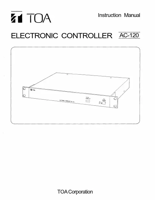
Instruction Manual ELECTRONIC CONTROLLER AC-120ContentsUser precautions General description FeaturesPanel facilities ConnectionBlock diagram Specifications Appearance 2 2 2 3 4 5 6 7User PrecautionsThe AC-120 cannot be used for the following outdoor speaker (splash-proof) models ofthe F-500 and F-600 series : F-500WP, F-500WP-L, F-600WP, and F-600WP-L.To avoid severe electrical shocks, never open the unit nor touch its internal parts norinsert hair pins, etc. into the unit.Water in the unit can be extremely destructive and dangerous. If water does get into theunit, make no further attempt to use the unit. Instead, switch the power OFF at once,unplug the power cord from a wall outlet, and then inform your nearest TOA dealer.To clean the unit's exterior, wipe with a soft damp cloth lightly soaked in water or aneutral detergent. Never use thinner, benzine, or other solvents, which may discolor theunit's surface.General DescriptionThe TOA AC-120 is an electronic controller designed for use with the F-120C ceiling speaker. It can be used to enhance sound quality of the F-500 and F-600 series speaker systems.Features1. Mountable in an EIA standard 19" rack. (1-unit size)2. Electronically-balanced I/O jacks. (Pin No.3 : HOT / No.2 : COLD / No.1 : GND)3. Output for subwoofers.4. A switch to cut low frequencies for the F-120C speaker.Panel FacilitiesFront PanelRear PanelLow Cut Indicator (IN)Lights when the low cut switch is pressed.Power IndicatorLights when the power is switched on.Low Cut Switch (LOW CUT)Pressing this switch when the equalizer selection switch is set to "F-120C" position cutslow frequencies.Power Switch (POWER)Press this switch to turn power on. To turn power off, press this switch again.Ground TerminalBe sure to ground the unit.When other components are connected, a ground loop can be created, generatinghum. In such cases, remove a shorting piece.Normally, use the unit with the shorting piece attached.Equalizer Selection Switch (EQ)Set this switch to "F-120C" position if the F-120C speaker is connected, and to"F-500/600 SERIES" position if the F-500 or F-600 speaker is connected.Low Frequency Output Jack (LOW OUT)This electronically-balanced jack connects to a subwoofer.Cut-off frequency is 100Hz (Cut-off frequency slope —12dB/Oct).Output Jack (OUTPUT)This electronically-balanced jack connects to a power amplifier.Input Jack (INPUT)This electronically-balanced jack is an input for external equipment.ConnectionNo subwoofer is used.Mixer/ Preamplifier Ch.1Ch.2ElectronicControllerAC-120Ch.1Ch.2Power AmplifierSpeakerSpeakerA subwoofer is used.Mixer/ Preamplifier Ch.1Ch.2ElectronicControllerAC-120Ch.1Ch.2Low OutPower AmplifierSpeakerSpeakerSubwooferNote1. Set the equalizer selection switch (EQ) depending on the type of connected speakers.2. The AC-120 cannot be used for the following outdoor speaker (splash-proof) modelsof the F-500 and F-600 series : F-500WP, F-500WP-L, F-600WP, and F-600WP-L.Block DiagramSpecificationsPower Requirements Power Consumption DistortionHum & Noise Channel Input Channel OutputLow Frequency OutputLow Frequency Cut FinishDimensionsWeight AC Mains, 50Hz/60Hz9WLess than 0.05% ( + 4dB* 1kHz)Less than –94dB* (20Hz~20kHz)Rated input : +4dB*electronically-balanced phone jack Max. input level : +20dB*Rated output : +4dB*electronically-balanced phone jack Max. output level : +20dB*Rated output : +4dB*electronically-balanced phone jack Max. output level : +20dB*Filter : Cutoff frequency slope 12dB/Oct 100Hz6dB cut at 100Hz (F-120C used)Panel : Aluminum (colored Alumirite), black482.6(W) X 44(H) x 297.5(D)mm [19.00" x 1.73" x 11.71"]3.7kg [8.16 Ib.]0dB = 0.775V RMSSpecifications are subject to change without notice. Accessories :Instruction manualWarranty card (for USA and Canada only)1 1AppearanceUnit : mm(in)。
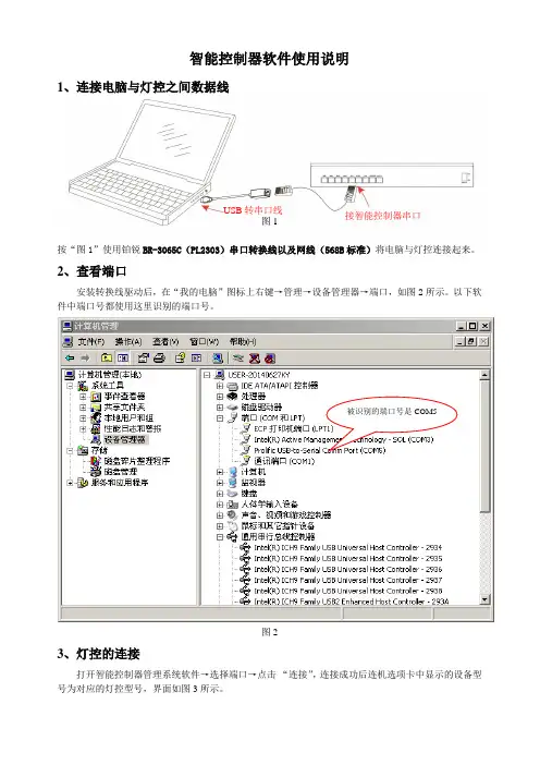
尊敬的用户:感谢您使用XXXXXXXX 的产品,请您在使用前熟悉该说明书,掌握产品的卓越功能,使该产品发挥应有的效能。
主要用途:LED 灯饰集中编码智能遥控控制系统,是一种可广泛应用于宾馆、酒店、家庭客厅、房间、办公场地的LED 灯饰进行编码智能遥控控制的智能化控制系统,该系统可对LED 灯饰进行开关、调光、定时、装饰灯色彩的集中编码遥控控制;即分别通过对各种LED 灯饰进行编码,然后用该智能控制器对各种编码的LED 灯饰进行单独遥控控制;分组遥控控制;全部同时遥控控制。
减少线路布线和日常维护,通过增加的调光和定时功能节能降耗,通过对新增颜色调节功能的灯具的调节,增加装饰灯的观赏性,该智能控制器的使用,使一种灯饰配一只遥控器改变为一只遥控器可遥控多种灯饰或电器(1-225),给操作使用灯饰带来方便。
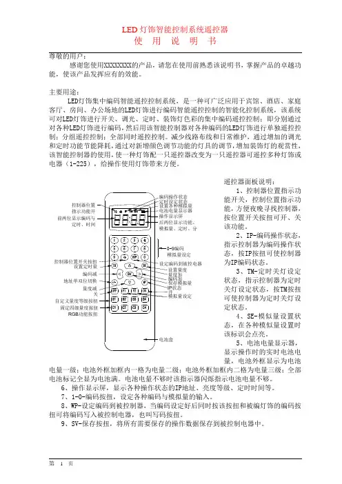
遥控器面板说明:1、控制器位置指示功能开关,控制位置指示功能,方便夜晚寻找控制器,按位置开关按扭可开、关该功能。
2、IP-编码操作状态,指示控制器为编码操作状态,按IP 按扭可使控制器为IP 编码状态。
3、TM-定时关灯设定状态,指示控制器为定时关灯设定状态,按TM 按扭可使控制器为定时关灯设定状态。
4、SE-模似量设置状态,在各种模似量设置时该标识会点亮。
5、电池电量显示器,显示操作时的实时电池电量,电池外框显示为电池电量一级;电池外框加框内一格为电量二级;电池外框加框内二格为电量三级;全部电池标记全显为电池满。
电池电量不够时该指示器闪烁指示电池电量不够。
6、操作显示屏,显示各种操作状态的IP 地址、亮度等级、定时时间等。
7、1-0-编码按扭,设定各种编码与模拟量的输入。
8、WP-设定编码到被控制器,当编码设定好后同时按该按扭和被编灯饰的编码按扭可将编码写入被控制电器,也叫写码按扭。
9、SV-保存按扭,将所有需要保存的操作数据保存到被控制电器中。
状态RGB 9编码前两位显示编码与定时、时间控制器位置指示功能开10、< >编码加、编码减,加减灯饰IP地址编码。
智能遥控的操作方法
智能遥控的操作方法因不同品牌和型号的智能遥控器而异,以下是一般智能遥控器的操作方法流程:
1. 将智能遥控器与设备配对:通常需要按下设备上的配对按钮(如电视机上的配对按钮)或按下遥控器上的配对按钮,直到两者成功连接。
2. 开关控制:根据需要,按下智能遥控器上的电源按钮可以打开或关闭设备。
3. 功能选择:智能遥控器上通常有数字按钮、音量按钮、频道按钮等,用于选择不同的功能。
按下相应的按钮可以切换电视频道、调整音量大小等。
4. 菜单导航:一些智能遥控器上还有导航按钮(如方向键、OK键、返回键等),用于操作设备上的菜单。
按下相应的按钮可以在电视菜单或其他设备菜单中进行导航和选择。
5. 额外功能:一些智能遥控器还具有额外的功能按钮,如静音按钮、快进按钮、回放按钮等。
按下相应的按钮可以执行相应的操作。
需要注意的是,不同品牌和型号的智能遥控器可能具有一些特殊功能或操作方法,用户可以参考相应的产品说明书或在设备的官方网站上查找更详细的操作指南。
同时,一些智能遥控器还支持语音控制或智能手机应用程序操控,用户可以根据实际需求选择相应的操作方法。
USER MANUALMODEL 1200/1201SynchronousModem EliminatorSALES OFFICE (301) 975-1000TECHNICAL SUPPORT P/N: 07M1200-CDoc# 049011U,Rev. DRevised 1/22/081.0Warranty Information (5)1.1Warranty Statement (5)1.2Radio and TV Interference (5)1.3CE Notice (6)1.4Service (6)2.0General Information (7)2.1Features (7)2.2Description (7)3.0Installation (8)4.0Configuration (9)4.1Data Rate (9)4.2Carrier Detect (9)4.3RTS/CTS Delay (10)4.4Ground (10)5.0Operation (11)5.1LED Status Indicators (Model 1201 only) (11)A Specifications (12)A.1Data Rates (12)A.2Clocking (12)A.3Grounding (12)A.4Range (12)A.5Functional (12)A.6RTS/CTS Delay (12)A.7DCD (12)A.8Ring Indicator (12)A.9Interface (12)A.10Connectors (12)A.11Power Supply (12)A.12Altitude (12)A.13Humidity (12)A.14Dimensions (12)B Block Diagram (13)1.0 WARRANTY INFORMATIONPatton Electronics warrants all Model 1200/1201 components to be free from defects, and will—at our option—repair or replace the product should it fail within one year from the first date of shipment.1.1 WARRANTY STATEMENTPatton Electronics warrants all Model 2701RC Series components to be free from defects, and will—at our option—repair or replace the prod-uct should it fail within one year from the first date of shipment. This war-ranty is limited to defects in workmanship or materials, and does not cover customer damage, abuse, or unauthorized modification. This prod-uct contains no serviceable parts; therefore the user shall not attempt to modify the unit in any way. If this product fails or does not perform as warranted, your sole recourse shall be repair or replacement as described above. Under no condition shall Patton Electronics be liable for any damages incurred by the use of this product. These damages include, but are not limited to, the following: lost profits, lost savings and incidental or consequential damages arising from the use of or inability to use this product. Patton Electronics specifically disclaims all other war-ranties, expressed or implied, and the installation or use of this product shall be deemed an acceptance of these terms by the user. In the event the user detects intermittent or continuous product malfunction due to nearby high power transmitting radio frequency equipment, the user is strongly advised to use only data cables with an external outer shield bonded to a metal or metalized connector.1.2 RADIO AND TV INTERFERENCEThe Model 1200/1201 generates and uses radio frequency energy, and if not installed and used properly-that is, in strict accordance with the man-ufacturer’s instructions-may cause interference to radio and television reception. The Model 1200/1201 has been tested and found to comply with the limits for a Class A computing device in accordance with specifi-cations in Subpart B of Part 15 of FCC rules, which are designed to pro-vide reasonable protection from such interference in a commercial installation. However, there is no guarantee that interference will not occur in a particular installation. If the Model 1200/1201 does cause interference to radio or television reception, which can be determined by disconnecting the unit , the user is encouraged to try to correct the inter-ference by one or more of the following measures: moving the computing equipment away from the receiver, re-orienting the receiving antenna and/or plugging the receiving equipment into a different AC outlet (such that the computing equipment and receiver are on different branches).1.3 CE NOTICEThe CE symbol on your Patton Electronics equipment indicates that it is in compliance with the Electromagnetic Compatibility (EMC) directive and the Low Voltage Directive (LVD) of the European Union (EU). A Cer-tificate of Compliance is available by contacting Technical Support.This device is not intended to be connected to the publictelephone network.Caution1.4 SERVICEAll warranty and nonwarranty repairs must be returned freight prepaid and insured to Patton Electronics. All returns must have a Return Materi-als Authorization number on the outside of the shipping container. This number may be obtained from Patton Electronics T echnical Services at:•Tel: +1(301) 975-1007•Email: ******************•URL: Note Packages received without an RMA number will not beaccepted.2.0 GENERAL INFORMATIONThank you for your purchase of this Patton Electronics product. This product has been thoroughly inspected and tested and is warranted for One Y ear parts and labor. If any questions or problems arise during installation or use of this product, please contact Patton Electronics Customer Service at (301) 975-1007.2.1 FEATURES•Smallest synchronous modem eliminator available•Data rates to 38.4 Kbps•Synchronous cable runs to 300 feet on each side of device •Constant or RTS controlled carrier selections•RTS-CTS delay options of 0mS, 6.6mS or 53mS•DB-25 connector on each end•Half or full duplex•Internal or external clocking•No external power required•LEDs monitor data and control signals (Model 1201 only)2.2 DESCRIPTIONMeasuring only 5.3 x 2 x 1.2 inches, the Patton Model 1200 is the small-est self-powered synchronous modem eliminator on the market. All power is derived from the RS-232 data signals, so no AC power or bat-teries are required. Constructed with a DB-25 connector on each end, the Model 1200 can extend synchronous cable runs to 300 feet on each side of the device. Optimum distance is achieved at 9600 bps, and strap selectable data rates may extend up to 38,400 bps.The Model 1200 provides internal or external clock options and operates half or full duplex. To emulate dial-up or dedicated service, the delay between RTS and CTS can be set to either 0mS, 6.6mS or 53mS. The carrier can be configured either as “constantly on” or “controlled by RTS”. The Model 1201 has all the features of the Model 1200, plus LED indica-tors that monitor receive data, request to send and data carrier detect on each side of the device.Do the following to install the Patton Model 1200:1.Configure according to the instructions listed in section 4.0, “Config-uration” on page 7.2.Turn off the computer or device to which the Model 1200 is to beconnected.3.Plug the DB-25 connectors directly into the serial ports of your RS-232 devices. If you wish to extend the distance, you can add cableson both sides (see Figure 1).Note Cables must not be longer than 300 feet (see Figure 1).Figure 1.ConfigurationThe Model 1200 is equipped with four strapping options that allow config-uration to a wide range of applications. To gain access to the internal straps, loosen the hex nuts on the DB-25 connectors and pry open the case between the plastic shell ears. Figure 2 shows the location of each strapping option.Figure 2. Strap settings for the Model 1200/12014.1 DATA RATEThe data rate strap controls the rate at which data is transmitted. Adjust the strap to select one of the following options: 1.2, 2.4, 4.8, 9.6, 19.2, 38.4 or external clocking. If “external clocking” is selected, the Model 1200 will automatically match the clocking between your two synchro-nous devices. The default setting is 9.6 Kbps.4.2 CARRIER DETECTThe carrier detect straps allow you to determine whether the carrier is “constantly on” or “controlled by RTS”. By adjusting the strap, you may operate in switched carrier, multi-point and/or hardware handshaking applications. Port 1 and port 2 may be configured separately. The defaults setting is “on” for both ports.4.3 RTS/CTS DELAYThe RTS/CTS delay straps determine the amount of delay between the time the Model 1200 “sees” RTS and when it sends CTS. In order to emulate either dial-up or leased line modems, you can set this strap at either no delay, 6.6mS or 53mS. Port 1 and port 2 may be configured separately. The default setting is 6.6mS for both ports.4.4 GROUNDThe ground strap setting connects the protective ground from port 1 or 2 to the Model 1200’s signal ground. The default setting is port 1.5.0 OPERATIONOnce you have configured the Model 1200 properly (see section 4.0, “Configuration” on page 7) and plugged it into your equipment, you are ready to operate the unit. After the Model 1200 is properly installed, it should operate transparently—as if it were a standard cable connection. Operating power is derived from the RS-232 data and control signals; there is no “ON/OFF” switch.5.1 LED STATUS INDICATORS (MODEL 1201 ONLY)The Model 1201 features six front panel status LEDs that indicate the condition of the modem eliminator and the communication link. The dia-gram below shows the location of each of these LEDs. Following the dia-gram is a description of each LED’s function.•“TD” and “RTS” indicators blink with data activity.•“CD” lights for an incoming signal on the line side and the resulting out-put signal on the RS-232.APPENDIX ASPECIFICATIONSA.1 DATA RATESSelectable: 1200, 2400, 4800, 9600, 19200, 38400A.2 CLOCKINGInternal or externalA.3 GROUNDINGProtective ground (pin 1) may be strapped to signal ground (pin 7)A.4 RANGE300 feet on either side (for a total of 600 feet) at 9600 bps, range extends linearly for lower bit rates and decreases for higher bit ratesA.5 FUNCTIONALEmulates half or full duplex, dial-up or dedicated lineA.6 RTS/CTS DELAYSelectable per port: 0mS, 6.6mS, 53mSA.7 DCDSelectable per port: continuous or RTS controlledA.8 RING INDICATORConstantly onA.9 INTERFACEEIA RS-232C/CCITT V.24A.10 CONNECTORSChoice of two male or two female DB-25 RS-232 connectorsA.11 POWER SUPPLYNone requiredA.12 ALTITUDE0 to 10,000 feetA.13 HUMIDITYUp to 95% non-condensingA.14 DIMENSIONSApproximately 5.3 x 2 x 1.2 in.APPENDIX BBLOCK DIAGRAMCopyright © 2001 Patton Electronics Company All Rights Reserved.Dear Valued Customer,Thank you for purchasing Patton Electronics products! We do appreci-ate your business. I trust that you find this user manual helpful.We manufacture one of the widest selections of data communications products in the world including CSU/DSU's, network termination units, powered and self-powered short range modems, fiber optic modems, interface converters, baluns, electronic data switches, data-line surge protectors, multiplexers, transceivers, hubs, print servers and much more. We produce these products at our Gaithersburg, MD, USA, facility, and can custom manufacture products for your unique needs.We would like to hear from you. Please contact us in any of the following ways to tell us how you like this product and how we can meet your prod-uct needs today and in the future.Web: Sales E-mail: ****************SupportE-mail:******************Phone - Sales (301) 975-1000Phone - Support (301) 975-1007Fax: (301) 869-9293Mail: Patton Electronics Company7622 Rickenbacker DriveGaithersburg, MD 20879 USAWe are committed to a quality product at a quality price. Patton Electron-ics is ISO 9001 certified. We meet and exceed the highest standards in the industry (CE, UL, etc.).It is our business to serve you. If you are not satisfied with any aspect of this product or service provided by Patton Electronics or its distributors, please let us know.Thank you.Burton A.PattonVice PresidentP.S. Please tell us where you purchased this product.________________________________________________________ ________________________________________________________ ________________________________________________________。
智能遥控开关使用说明一产品概述:随着人们生活水平的不断提高,科学技术的不断进步,墙壁式的遥控开关正逐渐取代传统式机械开关,本公司研发生产的单线制数码无线遥控开关,突破了传统机械开关的开关方式,让人体验了高科技给生活.工作带来的方便和无限乐趣。
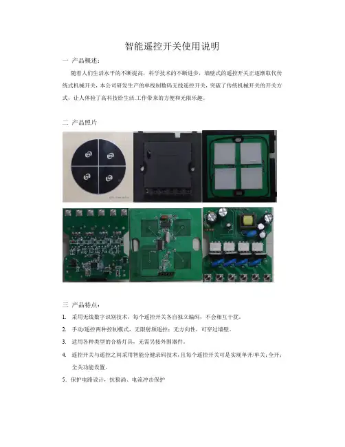
二产品照片三产品特点:1.采用无线数字识别技术,每个遥控开关各自独立编码,不会相互干扰。
2.手动/遥控两种控制模式,无限射频遥控;无方向性,可穿过墙壁。
3.适用各种类型的合格灯具,无需另接外围器件。
4.遥控开关与遥控之间采用智能分健录码技术,且每个遥控开关可是实现单开/单关;全开;全关功能设置。
5.保护电路设计,抗狼涌、电流冲击保护四主要技术指示:1.工作电压:ACC220V±15%2.额定功率(阻性负载)一位开关:3-200W二位开关:每路3-150W三位开关:每路3-100W3.注:如使用于日光灯或节能灯具,额定功率减半。
4.接收频率:315/433MHz(或定制其他频率)。
5.遥控距离:室内遥控距离≥30米,空旷地可视遥控距离≥50米五安装方法:遥控器开关的安装方法及接线方式通普通机械墙壁开关一样,安装前必须先切断电源,按遥控开关上的标签所示接线,并吧电线整理好,防止碰线短路造成遥控开关损坏。
严禁灯头或负载短路,严禁同时在接线柱上直接接入火线和零线,以免造成电源短路。
六遥控码录入遥控开关的方法:遥控开关出厂时,已清空遥控码,请按照如下方法录入遥控器:1.单开/单关:在所有灯光熄灭的状态下,按住设置的遥控开关面板某路按键3秒,待面板指示灯由红色变成蓝色后,松开面板按键,接着按一下遥控器上想要控制该路的按键,待面板指示灯由蓝色变成红色后学习完毕。
遥控开关其他各路录入的方法相同。
2.清除已学习的遥控码:在所有灯光熄灭的状态下,按住开关面板的任意一路按键10秒,待面板指示灯由红变蓝再变红,即灯“灭——亮——灭”后松手,这时遥控开关面板录入的所有遥控器全部被清除。
用户手册ZHT-AC02D空调智能切换控制器目录第一章产品概述 (1)一.产品简介 (1)二.产品功能特性和技术参数 (1)1.主要功能特性 (1)2.技术参数 (1)三.安装环境 (2)第二章安装指引 (2)一.前面板 (2)二.前面板指示说明 (2)三.接口面板 (3)四.后面板接口说明 (3)五.智能控制启动系统定装与连接 (3)1.安装步骤 (3)2.实物联接图 (3)3.控制器接线说明 (3)第三章面板按键操作说明 (5)一.操作流程图 (5)二.系统设置说明 (5)1.part setting(参与设置) (5)bin setting(组合设置) (5)3.switch setting(切换设置) (5)4.single setting(单独设置) (6)5.sysclk setting(系统时间设置) (7)6.system resrt(系统复位) (7)7.learn code(学习红外码) (7)8.detece vol(电压检测) (7)9.temp mode(温度检测模式) (7)第四章故障及排除 (9)注意本手册仅供用户查阅参考,不提供任何形式的担保,产品规格型号如有修正或更改不再另行通告。
第一章产品概述一.产品简介ZHT-AC02D型空调切换控制器是一种豪华型智能空调启动控制系统,支持2台空调机。
实现单独或组合打包控制并监测空调机的运行状态,按照预先设置好的程序控制空调机的运行、停机及组合运行等。
实现市电断电再来电自动启动空调,智能控制空调机的切换运行,且支持联机使用上位机软件管理配置。
大大的提高了机房管理的效率,延长了空调的使用寿命。
适用于民用、商用、中小型机房、通信基站、UPS机房的各种品牌柜式、分体壁挂、吸顶式空调机等各种机型。
该系统具有报警和自动撤消报警功能,当空调处于报警状态时,如果空调恢复了正常状态,则取消报警。
ZHT-AC02D型空调切换控制系统功能齐全、性能优越、安装设置方便快捷,最经济的方式解决空调来电启动和智能切换实际问题,是您节省电力资源和人力资源成本的最佳选择。
智能遥控双向锁定平开门机安拓智能遥控平开门机使用手册安拓智能遥控双向锁定平开门机安拓智能遥控平开门机用户手册福州安拓智能科技有限责任公司一.概述二.安拓智能遥控系列平开门机结构与机型三.主要技术参数四.功能特点五.使用方法六.安装方法和调试七、维护与保养八、故障现象及检修方法九、安拓智能遥控系列平开门机标配装箱单十、安拓智能遥控系列平开门机部分选配件感谢您选用安拓智能遥控双向锁定平开门机!选用安拓智能遥控平开门机!安装使用前请您仔细阅读本手册,并认明商标、谨防假冒。
您若在使用中遇到需要帮助解决的问题,请联系当地经销商或福州安拓智能科技有限责任公司总部,我们将热忱为您服务。
安拓智能遥控双向锁定平开门机,安拓智能遥控平开门机是安拓智能科技有限责任公司研发的最新专利产品。
双向锁定平开门机不但能在关门位置把门自动锁在地铁上,还能在开门后把门自动锁在边上设定的挡铁上,防风,防拽,安全,可靠。
门机具有自动锁定机构,实现了驱动、锁定功能一体化;门机装在门上能自动升降,适应略有起伏的路面。
使用安拓智能系列平开门机,人在车内只要按动遥控器按钮上的“开”键,门机就会自动启动,把门打开,若使用安拓智能遥控双向锁定平开门机,当门开到边上设定的挡铁位置时,能自动把门锁到边上的挡铁上,防止被风打回来,确保行车,行人安全。
也可按动遥控器按钮上的“关”键,门机自动启动,把门推到关门位置并自动锁在地铁上。
还可以通过按动装在大门内侧壁上的控制器按钮实现自动开门,或自动关门锁定。
安拓智能系列平开门机是各种别墅门、庭院门实现自动化,智能化的理想选择。
二.安拓智能系列平开门机结构与机型1.安拓智能系列平开门机正面结构如图1所示。
2.安拓智能系列开门机侧面结构如图2所示。
附图 1 附图 2 3.主要机型ATG120 -SG型双向锁定型ATG120 -DG 型单向锁定型(普通型)三.主要技术参数四.功能特点1、双向锁定:在安拓智能系列产品中,智能遥控双向锁定平开门机不但能驱动门体在关门位置关门,实现遙控关门锁定,还能在门体开到最大位置或指定位置时,自动把门锁在边上的挡铁上。
BY220—AB智能遥控开关使用说明书
1.单开单关:在所有灯光熄灭的状态下,按住设置的遥控开关面板某路按键3秒,待面板指示灯由红色变成蓝色后松开面板按键,接着按一下遥控器上想要控制该路的按键,待面板指示永由蓝色变成红色后学习完华。
逦控开关其他各路录入的方法相同。
2.清除已学—习的延控码O在成有灯光熄灭的状态下,按住开关面板的任意一路按键10秒,待面板指亲T由红变蓝再变红戟'即好“炎甲亮·灭”后松手,这时遥控开关面板录入的所有遥控器全部被清除。
需重新进行录码才能进行詈控操作
3.特别提示:
(1)用户如需。
增加遥控器,按上述录入方法对应设置各路即可。
(2)每个遥控开关各路最多可以录入4组(次)遥控码,当进行3次录入时,则第一次录入的遥控码被清除,以此类推。
注意事项
1.遥控开关工作时,外壳有微热感属正常现象,建议不要超载使用,否则会缩短开关的使用寿命。
⒉遥控器使用过程中如发现遥控距离变近,指示灯变暗,请及时更换遥控器电池。
3.首次上电(包括停电又来电)遥控开关处于复位关断状态。
遥控开关的操作
通电后按遥控开关面板按键无反应。
1.检查是否接通电源,电压是否过低。
2.检查灯具是否损坏,是否接触不良。
3,检查接线是否正确,是否松动。
遥控开关面板可以开关,但遥控器不能控制。
1.检查遥控器是否与遥控开关学习对码。
用户安装好后,可重新进行学习对码,每路都要
单独对码。
2.。
检查遥控器是否损坏,按键时指示灯是否亮,不亮则遥控器有可能损坏,指示灯变暗,应更换同规格的新电池。
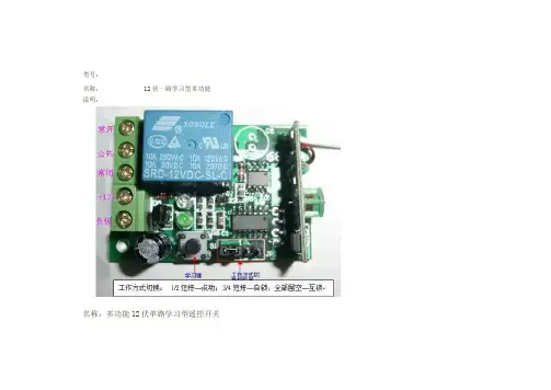
型号: 名称: 说明: 12 伏一路学习型多功能名称:多功能 12 伏单路学习型遥控开关型号:KST-RKX021 一、概述: 本公司设计、制造的多功能一路无线智能接收控制器,为一个继电器输出开关量信号,可使要控制的设备或电机 达到开关或通、断转换以及各种特殊控制程序的要求。
主要应用于电动门、窗、起吊设备、闸道、升降器、工业控制 及安防行业等领域。
该无线接收控制器,具高保密性,性能稳定、功耗低之特点,且使用方便,无需采用传统跳线或拨码开关编码, 只需将遥控器所发射的无线信号让该接收控制器接收并存贮, 即可实现配套使用。
其输出方式分别有三种自锁、 点动、 互锁。
二、输出方式(特别提醒:切换工作方式需先断开电源方可正常工作) 特别提醒:切换工作方式需先断开电源方可正常工作 特别提醒 A、信号自锁——将 1、2 用短路冒短接 B、信号非锁——将 3、4 用短路冒短接(我们一般短这个) C、信号互锁——短路冒空置,不短接 三、学习方法 持续按住学习键三秒,红色指示灯闪烁表示进入学习状态,这时手应松开。
按遥控器任意键不停发射信号,指示灯闪 两次至灯灭表示学习成功。
持续按住学习键指示灯闪几次至灯灭可以清除接受控制器的记忆。
五、技术参数 1、工作电压:DC12V 2、工作电流:≤6mA 3、工作温度:-40℃ - +80℃ 4、接收频率:315MHz 433MHz 5、接收灵敏龋?SPAN lang=EN-US>-105Db 6、输出电压:交、直流可选 7、输出电流:≤10A 8、尺寸:48.2*32.8*15mm。
学习型万能遥控器使用说明学习型万能遥控器(也叫自拷贝遥控器,对拷遥控器)适合所有固定码芯片及学习型芯片,只要用户遥控器可以正常使用,芯片型号匹配即可以使用本款遥控器。
该遥控器具有价格便宜、操作简单、使用方便、适合范围广等特点。
本遥控器使普通买家增配遥控器变得非常简单,不需要过多的专业知识,不用对遥控器进行编码设置,轻松几步就能快速复制品种繁多的同频率的固定码遥控器,也可将二个或多个芯片兼容,频率一致遥控器的部分功能合并在一个遥控器上使用,可拷贝市面上绝大多数的无线遥控器(家用防盗遥控器、汽车后加装的防盗遥控器、摩托车防盗遥控器、电动车防盗遥控器、卷闸门遥控器、车库门遥控器、电动门遥控器等等),不适合汽车原装遥控和双向遥控器,不适合滚动码遥控器。
一、确定是否能用对拷遥控器; 原遥控正常,芯片兼容,频率正确是选用对拷遥控器必备的三个条件。
购买前先确定你现在在用的遥控器的按键是绝对好的,外观无所谓。
再打开你的遥控器查看芯片型号和频率。
为节省大家的宝贵的时间,请在联系我们之前先抄下您的芯片型号和频率,直接报给我们,我们会为您确认是否能用的。
查看方法:如果您的遥控器不是汽车原装遥控和双向遥控器。
请打开您的遥控器外壳,查看里面的线路板:查找芯片:一个多脚的黑色元件(8脚、16脚或18脚以上),上面印有的文字(英文加数字)就是芯片型号。
固定码遥控器常用芯片有PT2260、PT2262、PT2264、PT2240、SC2260、SC2262、CS5211、HX2260、HX2262、HS2262、EV1527、HS1527、HX1527等,芯片型号只需对上数字部分就可以确定是类型了,所有固定码的遥控器都适用。
滚动码或隐藏码的不适用,滚动码遥控器芯片的常用芯片有HSC200、HSC201、HSC300、HSC301等。
查找声表:一个长条形或圆形的银色的元件上面的文字(英文加数字),常见的有NDR315、315、330、433等,各个款式的遥控器可能所处的位置不一样,元器件也可能不同,但都是铁质的,圆形长形居多,实际中也有不带可调电容,也没有声表元件的遥控器,频率不能目测测定 如果没有频率计,以上两种情况只能选用可调频率的对拷遥控器频率能够确定但不是315M、433M时,也只能选用可调频率的对拷遥控器。
CD、CH、CB系列ST8000系列智能温度调节仪操作手册简介CD、CH、CB系列(ST-8000)智能能温度控制器是采用专用微处理器的多功能调节仪表,它采用开关电源和表面贴装技术(SMT),因而仪表精致小巧,性能可靠。
特有的自诊断功能,自整定功能和智能控制功能,使操作者可以通过简单的操作而获得良好的效果。
主要技术指标●输入各种热电偶(TC)、热电偶(RTD)标准电流电压信号(见输入类型表)●精度测量精度:±0.5%FS冷端补偿误差:±2℃(0~50℃范围内可软件修正)分辨力:14Bit采样周期:0.5See●显示过程值(PV)、设定值(SV)、:-1999~+9999输出、报警、自整定状态指示:LED●控制输出1.电流输出:DC 0~10mA,4~20mA(RL<500Ω)2.电压输出:DC 0~5V,1~5V(RL>10K)3.继电器输出:触点容量250VAC 3A(阻性负载)4.电压脉冲输出:0~12V(适用于固态继电器SSR)5.可控硅SCR输出:过零触发或移相触发(阻性负载)6.报警功能输出:最多二组输出,12种模式输出触点容量:250VAC 3A(阻性负载)●设定范围设定值(SV):同量程(PV)比例带(P):0~全量程(设0时为ON/OFF控制)积分时间(I):0~3600Sec(设0时无积分作用)微分时间(D):0~3600Sec(设0时无积分作用)比例周期:1~100Sec位式控制输出滞环宽度:1~100℃(或其它PV单位)●其它1.绝缘电阻:>50M(500VDC)2.绝缘强度:1500VAC/1分钟3.功耗:<10VA4.使用环境:0~50℃,30~85%RH的无腐蚀性气体的场合5.重量:约0.5Kg(C900 STA)外型、按装开孔及接线●外型及开孔尺寸外形尺寸●接线图(有特殊订货以仪表本身接线图为准)●型号命名*1自主较正功能不能用于W.A类型。
Cordless Vacuum | AR1201Important Safety InstructionsPlease do not use device near any form of heat sources.Please use accessories specified and provided by the manufacturer.Please refer all servicing to qualified personnel should there be any form of damage to the device. Keep this user manual for future reference/ troubleshooting.Please heed ALL safety cautions.1.2.3.4.5.SAFETY CAUTIONSUnboxingKeep device AWAY from fire and heat sources at all times.Do NOT attempt to disassemble or alter the device.Do NOT expose the device to excessive heat. (Direct sunlight e.g.).Do NOT immerse/ expose device to any form of fluids. Product label is located at the bottom of the product.Keep hair, loose clothing or any body parts away from any openings / moving parts.Turn off all controls before unplugging the device.Unplug from power outlet when not in use and before servicing.Do not use without dust bag and/or filter in place.Do not attempt to suck up anything that is burning. (Cigarettes, hot ashes etc. )1.2.3.4.5.6.7.8.9.10.Handle - motor assembly Main tube Floor brush/ NozzleAdapterDevice OverviewDevice Assembly* Please refrain from using any damaged components. Contact your local authorisedaiwa distributor/customer service. *Attach floor brush to main tube.Attach main tube to motor-handle assembly.Handle Power buttonSpeed variation switchTube release buttonMain tubeBattery compartment Dust cupDust cup release buttonDust cup filter Dust cupSuction - Floor brushDevice AssemblyORWall mount charger assemblyDust cup installationAttach floor brush to motor - handle assembly.Insert power cord into opening of the power cord holder as shown.Install power cord holder on the main mount.Install complete wall mount on wall.Click!Device Walkthrough - Power ON / OFFDevice Walkthrough - Suction mode variationDevice Walkthrough - Battery & Charging* LED lights will illuminate upon device being turned on. *Press to variate between 2 available suction modes(High speed / Quiet Mode).Press to start up.Connect charging cable to any power source and the AR1201 as shown.(Connect directly/ via wall mount)Charging time - Approx. 4 - 5 Hours Run time - Approx. 40 Minutes*Charging indicator light lights up red (0%-50% Charge)**Charging indicator light lights up orange (50%-90% Charge)**Charging indicator light lights up green (90%-100%% Charge)**Battery discharge - Low discharge (Green), High discharge (Orange)*Cleaning & maintenance - Waste RemovalCleaning & maintenance - Washing the dust cup & filterTroubleshootingRemove filter fromdust cup.Wash dust cup with a soft sponge/ brush and warm water.Wash filter withwarm water.Remove dust cup via dust cup release button.Release waste via waste releasemechanism as shown.*For optimal performance always empty dust cup container after each use.**Air dry dust cup filter before reinstallation.*The vacuum could not be turned on.Ensure device is charged.The vacuum is weaker.1. Ensure filter is cleaned and there is no obstructions present near the intake & throughout the vacuum suction pipe.2. Ensure device is charged.TroubleshootingCustomer serviceDevice specificationsThere is a leakage of waste.1. Ensure dust cup is empty.2. The dust cup might not be installed properly. Re-install dust cup filter.It is recommended to replace the dust cup filter every three (3) months (subjected to usage frequency) to ensure peak performance of the unit.For more product information please visit .Contact your local authorised dealer/ customer service. Refer to the warranty label provided in the box.Limited WarrantyPlease refer to the warranty label provided in the box.Note: Disassembling device voids warranty. Note: Liquid submersion voids warranty.Model - AR1201Rated total power consumption - 120W Rated current/ voltage - 500mA/ 26.5V Battery - Li-on 2200mAh Charging time - 4-5 Hours Pressure - ≥ 9.0kpa or 5.0kpaNoise level - 68 dB Size - 425*100*150mm Dust cup capacity - 300ml Weight ≈ net: 2.3kg, Gross: 3.7kg無線吸塵器使用說明書Instruction Manual在使用本產品之前,請務必先仔細閱讀說明書。
本文部分内容来自网络整理,本司不为其真实性负责,如有异议或侵权请及时联系,本司将立即删除!== 本文为word格式,下载后可方便编辑和修改! ==智能开关面板说明书篇一:通用智能开关使用说明书智能开关使用说明书————一/二/三位暗装智能开关尊敬的用户:首先感谢您选择了我公司的智能产品,智能科技有限公司全体同仁祝您全家生活愉快!我们的产品将给您的生活带来舒适和便捷,为了让您能更好的安装和使用该产品,在这里我们提醒您认真阅读此说明书。
如有疑问请登联系我们,我们竭诚为您服务。
一、产品说明NT-JJ3309型一位暗装智能开关,NT-JJ3310型二位暗装智能开关,NT-JJ3311型三位暗装智能开关是尼特智能开关系列产品之一,它主要用于控制灯具及电器的开关。
其外型尺寸为86×86×45,可与普通86型开关互换安装,不仅可直接取代传统的墙壁开关,保留原有手动功能,而且增加了射频遥控、远程电话遥控、远程网络遥控等具有现代意识的数字化功能,是现代家居智能化的理想选择。
二、产品图示及接线图、安装图、拆卸图一位暗装智能开关二位暗装智能开关三位暗装智能开关N(零线)灯泡1N(零线)灯泡1N(零线)灯泡1一位暗装智能开关三位暗装智能开关二位暗装智能开关接线图接线图接线图三、安全警示拆卸图1、为了您的安全,在使用本产品之前必须详读此说明书。
2、聘请专业电工为您安装或拆卸开关,安装或拆卸开关时,必须先切断电源。
3、本开关安装在洗漱间、浴室等潮湿的地方时应装防溅盒或采取防潮措施。
4、配接负载时应严格控制在负载功率之内。
5、安装开关时严禁锤打、过力紧固以防面板变形,同时严禁金属物掉入开关外壳内。
四、概念解释:1、学习状态:此时可以把遥控器的某一指令代码,存储于开关(插座、单路控制器)的记忆芯片中,从而实现两者之间的相互确认2、对码:实现遥控器和开关(插座、单路控制器)的相互确认。
如果不进行对码,遥控器则不能控制该开关(插座、单路控制器)3、数字对码:实现遥控器数字键和开关(插座、单路控制器)的相互确认。