方正飞旋标引反解系统V5.2.7使用手册
- 格式:pdf
- 大小:5.00 MB
- 文档页数:72

印刷世界2008.11方正飞腾4.1排版软件使用心得漫谈昆明日报社技术中心马飞5飞腾输出PDF插件可移植文档格式(PortableDocumentFormat,简称PDF)是全球电子版文档分发的公开实用标准。
PDF是一种通用文件格式,能够保存任何源文档的所有字体、格式、颜色和图形,而不管创建该文档所使用的应用程序和平台。
已成为全世界各种标准组织用来进行更加安全可靠的电子文档分发和交换的出版规范,已经在各企业、政府机构和教育工作者中广为使用,以期简化文档交换、提高生产率、省却纸张流程,是文档资料网络传播的行业标准格式。
任何人都可以使用免费的AdobeAcrobatReader共享、查看、浏览和打印PDF文件。
PDF文件可以在任何介质上进行发布:通过打印附加到电子邮件上、公司服务器上、因特网站上、或在CD-ROM上。
压缩的AdobePDF文件比源文件小,每次下载一页,可以在网页上快速显示,而且不会降低网络速度。
针对使用方正飞腾进行排版工作的单位,需要将排版的结果转换为PDF格式的文档以便制作光盘和网上出版,方正提供了飞腾输出PDF插件,它能将方正飞腾4.1的排版结果输出为PDF文档。
通过方正飞腾输出PDF插件,可以将版面的整体效果转换成PDF文件,然后放到网络上或者通过电子邮件等方式发给需要进行校对或是确认大样的人士,他们可以在家里,通过收到的PDF文件可以直接确认整体效果和具体内容。
运用方正飞腾PDF插件生成的PDF文件,可以有如下用途:1)制作电子刊物,直接用于网络浏览。
2)进行远程校样,将生成的PDF文件通过网络传输进行校正,可大大提高校对工作效率。
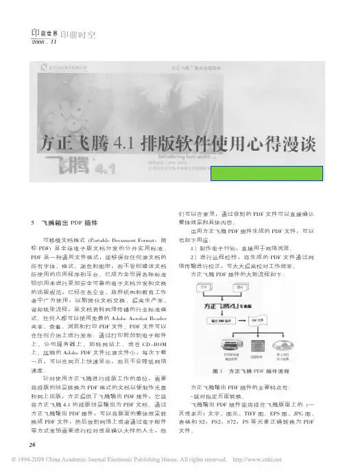
方正飞腾PDF插件的大致流程如下:方正飞腾输出PDF插件的主要特点有:·能对指定页面转换。
飞腾输出PDF插件能将排在飞腾版面上的(一页或多页)文字、图元、TIFF图、EPS图、JPG图、表格和S2,PS2,S72,PS等元素正确转换为PDF文件。

方正翔宇数字报刊系统解决方案第一章、方案的功能介绍1.1数字报刊是什么样子的1.2为数字报刊制作发布量身订造1.3数字报刊制作和发布流程1.4数字报刊为报社带来的益处1.5给读者带来的方便1.6方案的产品构成第二章、方案的产品介绍2.1方正飞旋反解标引软件2.2方正翔宇数字报刊系统2.3方正飞腾4.1专业版第三章、经典案例在网络信息时代,人们对新闻信息的需求表现出前所未有的强烈。
这种强烈的需求不仅仅体现在人们希望在第一时间获取最新、最全、最有深度的内容,而且希望能够在各种不同类型的媒介上都能够随时、随地、随需获取到丰富形式的信息。
大众不断发展的信息需求一方面推动着信息技术、网络技术、无线技术沿着各自的轨道独立发展;同时,也推动着各种技术在其发展过程中快速融合。
技术融合给信息传播和展现带来很多的全新发展机会;一方面信息内容的结构日趋丰富,另一方面内容的表现形式也随着传播媒介和涉众群体的特异性而呈现出多样化特征。
如何利用新兴的技术手段、新创的技术工具改造传统的生产流程实现信息内容的一次生成、多次发布的跨媒体生产是每个媒体都要面临的巨大挑战。
报刊媒体作为新闻信息最大的原创者,在这样的挑战下也应加快报刊数字化的步伐,利用先进的互联网技术使大众能够方便、快捷的浏览到数字化的报刊内容,充分发挥报社的资源优势,使新闻信息传播的更快、更广,提升报社网站对读者的吸引力。
方正翔宇数字报刊解决方案就是这样一套面向报刊媒体的跨媒体出版系统。
该系统通过整合北大方正的版面结构化描述技术、电子版面的生成技术、数字报纸的自动合成发布技术;同时新创了基于飞腾软插件实现的一系列版面内容快速智能反解标引技术,实现了报刊数字版面的快速、简洁但功能强大的网络化流水线式的跨媒体生成和发布。
方案的功能介绍数字报刊是什么样子的数字报刊首先要保持纸制报纸最吸引人的报纸版式,还要融合在互联网上阅读新闻的方便和快捷,方正翔宇数字报刊系统制作完成的数字报刊包括报纸原始的版面图,在版面图上点击感兴趣的文章直接弹出此篇文章的新闻内容,即保持原汁原味的报纸版式,符合传统看报习惯,又融合网上看新闻的方便快捷,吸引读者关注报社网站。


方正飞腾相当详细的使用说明带快捷键方正飞腾使用说明进阶(一)第1章一、飞腾排版系统总体的介绍在桌面出版系统中,用户首先面临的是版面的制作,不管是排报纸、杂志、书还是平面广告,都要处理文字、图形和图像等素材,并把这些素材安排在一个页面内,这个版面制作过程主要由排版软件来完成。
目的:排出版面更漂亮,并且符合传统习惯。
国内排版软件:1、飞腾、维思、pagemaker等交互式排版软件。
2、书版6.0、7.0、9.0批处理系统。
飞腾的历史:Fit1.0 在1994年出品。
Fit2.0 在1995年出品。
在1997年日版Fit推出进入日本市场。
Fit3.0 在1998年出品。
Fit4.0 在2001年出品。
Fit4.1 在2003年6月出品。
二、飞腾的典型安装1、安装加密锁运行飞腾时,机器必须安装加密锁。
否则,打开飞腾时,无反应,在安装飞腾前安装,而且是在关机时安装2、安装字体在安装软件前,先安装字体。
方正字体有兰亭(PC)和妙手(MAC)两种字库。
3、安装飞腾软件安装时用自定义安装,可安过滤器、输入法、插件、ODF图库最大页面值是958*958mm度量单位有:字、磅、毫米、英寸、厘米、级、PICA1磅=0.35mm=1/72英寸1英寸=2.54mm=72磅=6PICA1级=1/4mm=0.25mm三、工具条的介绍1、选取工具用于选取对象(多选:Shift、拖框选取)2、画图工具1)画线工具用于绘制线条,shift+绘制:水平、垂直或45度的线段。
可用选取工具选中线条两端的节点改变线的方向、长短2)画矩形工具用于绘制矩形、shift+工具绘制正方形,可用选取工具选中,出现8个节点,改变其大小。
■隐边矩形①选中矩形;②“美工”|“隐边矩形”3)画圆角矩形工具用于绘制圆角矩形,用法和矩形相似。
在此按钮上停一下,可绘制内圆角矩形。
属性在美工--圆角矩形--设置--确定四角连动:修改一个角的同时,其他角也相应改变,选中四角连动,只出现一个可调节的框。


P/N 561884 REV. A SEP 01REV. B FEB 08 O P E R A T I N G M A N U A L©2001 FISNAR INC.THIS PAGE IS INTENTIONALLY LEFT BLANK.- 2-SETTING UP AND OPERATING INSTRUCTIONS- 3 -1. Connect air hose to filtered compressed air 70 - 100 psi (5-7 bar) and connect fitting to the unit.2. Insert Foot Switch Plug.3. Insert and twist male quick connect into the unit.4. Insert power cord female plug into the unit and insert the male plug into a grounded outlet - check voltage label on back of unit.5. Turn unit on.6. Push foot pedal to create vacuum at pick-up tip.7. To increase vacuum, turn vacuum pick-up control counter clockwise. To decrease vacuum, turn vacuum pick-up control clockwise.8. Very small components can be picked up by using the vacuum pick-up tip only. The tip I.D. must be small enough to ensure that the component is not sucked in.AIR & ELECTRICAL SET UP DIAGRAMPOWER CORDAIR HOSECOMPRESSED AIRFOOT SWITCH PLUGFEMALE PLUGMALE QUICK CONNECTVACUUM PICK-UP PENCILVPP511-LFFOOT PEDALVACUUM PICK-UP TIPVACUUM PICK-UP CONTROLLIMITED WARRANTYManufacturer warrants this product to the original purchaser for a period of two (2) years from the date of purchase to be free from defects in material and workmanship, but not against damages caused by misuse, negligence, accident, faulty installation, abrasion, corrosion or by not operating in accordance with factory recommendations and instructions. Manufacturer will repair or replace (at factory's option), free of charge, any component of the equipment thus found to be defective, upon return of the component to the factory during the warranty period of the equipment. This warranty is valid only when 5 micron filtered air is used. The manufacturer's written liability, as stated herein, cannot be altered or enlarged except by a written statement signed by an officer of the company. In no event shall manufacturer be liable for consequential or incidental damages. A return authorization is required from FISNAR prior to shipping a defective unit to the factory.Manufacturer reserves the right to make engineering or product modifications without notice.- 4 -。

NCHRV5.7演⽰系统安装使⽤说明NCHR V5.7演⽰系统安装使⽤说明1前⾔本⽂档旨在帮助读者更快速的安装和使⽤我们所提供的NCHR V5.7演⽰系统包。
本⽂档包括对演⽰系统的安装说明、安装后系统的使⽤说明两个部分。
系统使⽤说明部分是对系统内置演⽰数据、内置⽤户等说明,不包含系统的详细功能操作说明。
如对系统功能操作有疑问,请查阅系统⽤户⼿册,或者使⽤系统提供的在线帮助。
1.1演⽰包包括的⽂件内容本次提供的演⽰包⼀共包括三个部分的内容:NCHR V5.7安装包,总裁桌⾯演⽰数据、演⽰数据库⽂件。
NCHR V5.7安装包:⽂件名为nchome.rar,包括了NCHR V5.7标准版、V5.7国企套件、⾃助服务、IUFO、总裁桌⾯五个部分的软件系统;演⽰数据库⽂件:⽂件名为nchr57demo.rar,则为上述四个部分对应的数据结构和演⽰数据。
总裁桌⾯安装包:⽂件名为总裁桌⾯Demo.rar,包括了总裁桌⾯的演⽰数据内容。
1.2演⽰系统包括的功能模块NCHR V5.7演⽰系统包包括了NCHR V5.7标准版提供的全部功能、V5.7国企套件将提供的3个业务模块功能、以及IUFO报表、决策分析中⼼(总裁桌⾯),是⼀个最完整的演⽰系统。
具体包括的功能模块为:NCHR V5.7标准版:UAP平台全部功能、⼈⼒资源基础设置、⼈⼒资源规划、⼈⼒资源预算、组织机构管理、⼈员信息管理、⼈员变动管理、⼈员合同管理、薪酬管理、福利管理、时间管理、招聘管理、培训管理、能⼒素质管理、绩效管理、政策制度、综合报表、⼈⼒办公平台;NCHR V5.7国企套件:⼲部管理、档案管理、问卷调查;⾃助服务:NCHR V5.7标准版、国企套件中各模块对应的⾃助部分功能,包含经理⾃助和员⼯⾃助;决策分析中⼼(总裁桌⾯):包括了决策分析模型设计、浏览功能;IUFO:包括报表制作、发布、浏览等功能。
2系统安装指南2.1指定安装路径选择好你要安装系统的路径,然后创建⼀个nchr57⽂件夹,然后在nchr57下在创建⼀个data⽂件夹;把nchome.rar⽂件拷贝到nchr57下,把总裁桌⾯Demo.rar、nchr57demo.rar拷贝到data⽬录下。

工具箱用户手册V 5.0版本方正国际软件有限公司2012年08月本手册内容改动及版本更新将不再另行通知。
本手册的范例中使用的人名、公司名和数据如果没有特别指明,均属虚构。
对于本手册及本手册涉及的技术和产品,方正国际软件有限公司拥有其专利、商标、著作权或其它知识产权,除非得到方正国际软件有限公司的书面许可,本手册不授予这些专利、商标、著作权或其它知识产权的许可。
版权所有©2011方正国际软件有限公司。
保留所有权利。
●Founder是北京北大方正集团公司的注册商标。
Pack#是方正国际软件有限公司的商标。
●Microsoft、Windows是Microsoft公司的商标或注册商标。
●其它标牌和产品名称是其各自公司的商标或注册商标。
●方正Pack#的一切有关权利属于方正国际软件有限公司所有。
●本手册中所涉及的软件产品及其后续升级产品均由方正国际软件有限公司制作并负责全权销售。
如果您对本产品有任何建议,请与以下地址联系:方正国际软件有限公司地址:北京市北四环西路52号方正国际大厦5层电话:(010)82179000传真:(010)82179001免费客服热线:4006800105邮编:100080网址:目录 1目录第1章工具箱 (2)1.1 工具箱的概念 (2)1.2 工具 (2)1.2.1 选择工具 (2)1.2.2 整体对象选择工具操作方法 (2)1.2.3 直接选择工具操作方法 (4)1.2.4 渐变编辑工具 (4)1.2.5 测量工具 (6)1.3 轮廓线处理器 (6)1.4 位图轮廓化 (8)1.5 十字线 (9)1.5.1 十字线工具 (9)1.5.2 对齐 (10)1.5.3 十字线添加为参考线: (16)1.5.4 裁切 (16)1.6 笔画扩缩 (17)1.7 节点优化 (18)1.8 非本机图稿转灰度图 (19)1.9 参考线管理器 (20)1.9.1 参考线管理 (20)1.9.2 切换参考线原点 (21)1.9.3 保存和打开参考线 (22)1.10 路径编辑工具 (22)1.10.1 重描工具: (22)1.10.2 重描另一边 (23)1.10.3 切割工具 (24)1.10.4 变形工具 (26)1.10.5 求交工具 (28)1.10.6 连接工具 (29)1.11 渐变加噪增强 (29)1.12 限制条件 (31)1.13 文字粘贴时不粘贴格式 (32)2 方正锐利包装软件V5.0使用手册第1章工具箱1.1 工具箱的概念工具箱主要由选择工具、渐变编辑工具、轮廓线处理器组成,与AI(以下简称AI)自带工具相比这些工具更加直观且易于操作。

方正畅流混合印刷流程系统v6.0快速入门北京北大方正电子有限公司2014年1月本手册内容改动及版本更新将不再另行通知。
本手册的范例中使用的人名、公司名和数据如果没有特别指明,均属虚构。
对于本手册、及本手册涉及的技术和产品,北京北大方正电子有限公司拥有其专利、商标、著作权或其它知识产权,除非得到北京北大方正电子有限公司的书面许可,本手册不授予这些专利、商标、著作权或其它知识产权的许可。
版权所有©(2001~2014)北京北大方正电子有限公司 保留所有权利Founder是北京北大方正集团公司的注册商标,畅流(ElecRoc)是北京北大方正电子有限公司的商标。
Microsoft、Windows、Windows Server 2003、2008和Windows XP、Windows 7是Microsoft公司的商标或注册商标。
其它标牌和产品名称是其各自公司的商标或注册商标。
方正畅流(ElecRoc)一切有关权利属于北京北大方正电子有限公司所有。
本手册中所涉及的软件产品及其后续升级产品均由北京北大方正电子有限公司制作并负责全权销售。
*本手册介绍了方正畅流系统的所有功能,但其中一些功能可能需要单独购买后才可使用,因此在界面与功能上会因实际购买情况的不同而有所差异。
需要另外购买的功能已使用*标注。
如欲了解更多信息,请咨询方正电子公司销售人员。
如果您对本产品有任何建议,请与以下地址联系:北京北大方正电子有限公司地址:北京市海淀区上地信息产业基地五街九号方正大厦电话:(010)82531188传真:(010)62981438邮编:100085方正客户服务中心:(010)82531688提供方正畅流系统的售后技术支持和服务网址:目 录目 录第1章 畅流服务器端快速入门 (1)1.1 畅流控制台 (1)1.2 权限控制 (2)1.3 启动处理器 (3)1.4 路径设置 (3)1.5 字体 (4)第2章 畅流客户端快速入门 (5)2.1 启动客户端 (5)2.2 使用管理工具 (6)1、用户与角色管理 (7)2、处理器管理 (9)3、资源处理管理 (11)4、折拼模板管理 (12)5、数码打样管理 (12)6、传统印刷管理 (13)7、数码印刷管理 (14)2.3 工作流程 (15)1、建立作业 (15)2、建立工作流程 (16)3、节点参数 (17)4、选取文件 (18)5、提交文件 (19)6、处理文件 (20)7、文件操作 (21)第1章 畅流服务器端快速入门 1第1章 畅流服务器端快速入门1.1 畅流控制台方正畅流服务器端安装完毕后,可通过“开始”→“程序”→“Founder Elecroc”→“畅流控制台”,或桌面上的控制台图标,启动服务器端控制程序-畅流控制台。

全媒体资源服务平台方案书北大方正电子2015年3月目录第1章全媒体资源库21.1方正畅享全媒体资源服务平台31.1.1系统概述31.1.2数据采集31.1.3编辑加工功能41.1.4图片管理101.1.5历史资料管理351.1.6全文检索351.1.7数据存储管理351.1.8系统管理361.1.9与相关业务系统的衔接38第2章硬件系统方案382.1服务器系统382.1.1数据库服务器402.1.2机集群系统架构402.1.3服务器推荐选型422.2存储系统43第3章投资匡算433.1产品报价43第1章全媒体资源库1.1方正畅享全媒体资源服务平台1.1.1系统概述近年来,报社的信息化建设高速发展,新媒体应用逐步展开,随之带来的是各种数据信息包括稿件、图片、版面文件、背景资料、视频、音频、甚至文档等多媒体信息成几何级数激增。
这些报社生产出来的海量的高价值信息和容需要安全、可靠的存储管理,以利于对这些数据进行有效、方便和充分的利用,加强信息资源的开发。
方正畅享全媒体资源服务平台作为方正报业全媒体解决方案的重要组成部分,将为报社构建新闻资源统一规存贮、共享,对容资源进行深度加工再利用,支持各业务系统快速应用的多媒体数字资源的整合平台。
通过对信息资源的整合、加工、挖掘,实现资源共享、信息增值与优质服务。
方正畅享全媒体资源服务平台在的各个功能的管理集成在统一的平台上,系统采用图形化人机对话界面设计,在统一的界面下使用按键式操作,操作使用简便。
后台采用大型关系型数据库系统作为系统主体数据库系统。
能将报社现有颐美图片存储系统存储的图片进行自动导库存储,并支持与相关业务系统的衔接。
1.1.2数据采集1.1.2.1飞旋反解利用方正飞旋反解工具,对Fit文件进行反解和标引,生成ps、pdf、版面图、小样、图片等容,并按日期版次规地放在文件目录下,由入库程序入到报刊成品库中。
1.1.2.2稿件分发程序文字、图片、图表、视频、音频、文档资源格式数据来源于不同的渠道,文件存放的目录结构也各不相同,通过稿件分发程序,按照入库程序的要求创建入库目录,并把文字稿件、图片等多媒体资源从原始目录下分发到入库目录下。
目录第1章软件介绍 (1)1.1软件主要功能 (1)1.2软件功能划分 (2)1.3简易教程 (3)1.4软件注册 (5)第2章项目管理 (8)2.1新建项目 (8)2.1.1坐标系统 (8)2.1.2数据字典 (14)2.1.3导入图层 (16)2.2打开项目 (17)2.3项目信息 (18)2.3.1 坐标系统修改 (19)2.3.2点校验 (19)2.3.3平面坐标系 (21)2.3.4大地坐标系 (22)2.4删除项目 (23)第3章图层管理 (25)3.1图层显示与隐藏 (25)3.2图层设置 (25)3.2.1图层样式 (26)3.2.2 标注样式 (27)3.2.3字段值渲染 (29)3.2.4可见比例尺 (29)3.3图层添加 (30)3.3.1新建图层 (30)3.3.2导入图层 (31)3.3.3新建图层(选择数据字典) (32)3.4图层顺序 (33)3.5删除图层 (34)第4章数据采集 (35)4.1采集主页面 (35)4.2数据采集方式 (38)4.3数据采集操作 (44)4.4数据删除 (46)4.5PPK采集 (46)4.6碎部点采集 (48)第5章草图 (50)5.1点 (50)5.2线 (50)5.3面 (50)5.4注记 (50)第6章数据编辑 (51)6.1移动 (52)6.2插入 (52)6.3删除 (53)第7章放样 (54)7.1设置放样点 (55)7.2放样 (59)7.3导航 (60)8.1图层数据查看 (61)8.2图层数据编辑 (64)8.3条件查询 (64)8.4电子围栏 (66)第9章数据导入导出 (68)9.1数据导入 (68)9.2数据导出 (68)第10章 GPS数据源 (70)10.1GPS数据源 (70)10.2网络差分 (75)10.3卫星视图 (79)10.4静态采集 (81)第11章轨迹 (83)11.1轨迹设置 (83)11.2轨迹查看 (83)11.3轨迹导出 (84)第12章云备份 (85)第13章系统设置 (86)13.1常用 (86)13.1.1单位设置 (86)13.1.2地图设置 (86)13.1.3采集设置 (89)13.1.4放样设置 (91)13.2显示 (92)13.2.1显示设置 (92)13.2.2快捷栏设置 (95)13.3位置 (96)13.3.1GPS数据源 (96)13.3.2网络差分 (96)13.3.3卫星视图 (96)13.3.4GPS设置 (96)13.4其他 (99)13.5注册关于 (100)13.5.1系统注册 (100)13.5.2帮助 (101)13.5.3常见问题 (101)13.5.4关于 (102)第14章多媒体 (103)14.1拍照 (103)14.2录像 (104)14.3录音 (105)第15章工具 (106)15.1坐标系统 (106)15.2数据字典 (109)15.3计算器 (109)15.4夹角计算 (110)15.5单位换算 (110)15.6测距仪 (111)15.7文件浏览 (111)第1章软件介绍1.1软件主要功能Hi-Q系列软件分为两款,分别为基础版Hi-Q软件和高级专业版Hi-Q Pro软件,其中Hi-Q Pro软件为收费软件,它从功能上更丰富,包含Hi-Q软件的全部功能,同时还包含以下功能:●坐标系统修改●点校验●云备份●新建图层●快捷栏设置●设置可见比例尺●条件查询●数据备份、数据恢复●字段筛选●电子围栏●草图●数据字典●量测(捕捉量测)●捕捉放样、AR放样(高级)●坐标转换、参数计算●自定义地图<Mapbox>、OGC地图服务●采集要素<捕捉、平滑、中心、偏距>、碎部点采集、PPK采集、静态采集●编辑要素<插入节点、删除节点、移动节点>●数据导入<dwg、dxf、gpx、kml、mif>●数据导出< shp、csv、txt 、dwg、dxf、kml、mif 、gpx>●轨迹设置、轨迹回放、轨迹导出<shp 、txt、csv、kml、gpx、dxf>1.2软件功能划分Hi-Q与Hi-Q Pro具体功能划分见下表:1.3简易教程简易教程以图片和标注的形式,简单示意了Hi-Q Pro 软件数据采集工作的操作流程。
Crusader VSLatheOperation ManualChester UK Lt dClwyd CloseHawarden Industrial Par k HawardenChester CH5 3PZTel: 01244 531631sales@chesterma ch i n www.ch esterma ch i n Contents1. Safety Rules for Lathes2. Machine Specification3. Constructional Indication4. Unpacking and Installation4.1. Unpacking4.2. Cleaning4.3. Installation5. Lubrication5.1. Headstock5.2. Gearbox5.3. Apron5.4. Change Gears5.5. Other Parts6. Test Running6.1. Spindle Speed Control6.2. Operation Symbols7. Thread and Feed Selection7.1. Thread and Feed Selection7.2. Feed and Thread Tables7.3. Threading Dial Indicator8. Chuck and Faceplate Removal/Installation 8.1. Chuck and Faceplate Removal8.2. Chuck and Faceplate Installation8.3. Camlock Stud Installation9. Maintenance and Servicing9.1 Lathe Alignment9.2 Saddle Strip9.3 Cross Slide9.4 Compound Rest9.5 Cross Slide Nut9.6 Tailstock Bed Clamp10. Parts List.Bed AssemblyHeadstock AssemblyFeed and Change Gearbox ControlApronCross Slide and CompoundTailstock AssemblySteady Rest and Follow RestCoolant System and CompoundElectric AssemblyOptional Accessories1. Safety Rules for LathesSafety is a combination of operator common sense and alertness at all times when the lathe is being used. Study these safety rules and general safety rules before operating and retain this manual for future use.1. Wear eye protection.2. Never attempt any operation or adjustment if the procedure is not understood.3. Keep fingers away from rotating parts and cutting tools while in operation.4. Never force the cutting action.5. Never perform an abnormal or little used operation without referring to the manualand without the use of adequate blocks, jig stops, fixtures etc.6. Use of a shop manual such as “machinery’s handbook” or similar is recommendedfor cutting speeds and operation detail.7. Do not remove the drive cover while the machine is in operation. Make sure thatit is always closed.8. Always remove the chuck key, even when the machine is not in operation.9. Do not attempt to adjust or remove tools when in operation.10. Always keep the cutters sharp.11. Never use the machine in an explosive atmosphere or where a spark could ignitea fire.12. Always use identical replacement parts when servicing the machine.Warning: Do allow familiarity (gained from frequent use of your lathe) to become commonplace. A careless fraction of a second can lead to severe injury.2. Machine SpecificationBench lathes are especially suitable for machining, tool toms and repairing working shops to machine shafts, sleeves and disc workpieces of medium and small sizes. They can also be used to cut metric thread and imperial, with compact construction and reasonable composition, they can cut very well. They are easy and reliable to operate, convenient to repair, high in efficiency and have low noise levels.Technical Specification3. Constructional IndicationNo Name No Name1 Speed selector 22 Apron2 Headstock 23 Threading cutting engagement lever3 DRO for spindle speeds 24 Control lever4 Feed direction selector 25 Cross travel control handwheel5 Change gear box 26 Saddle6 Feed box selectors 27 Cross slide7 Feed gear box 28 Support casting8 Demarcation frame work 29 Bed way9 Leadscrew and safety guide 30 Tailstock set-over screw10 Feed rod 31 Tailstock11 Control bar 32 Quill travel handwheel12 Oil Tray 33 Tailstock lock leer13 Left stand 34 Quill lock lever14 Indication light 35 Coolant system15 Inching Button 36 Compound rest handwheel16 Spindle speeds adjustable knob 37 Compound rest17 Coolant knob 38 Tool post18 Emergency stop button 39 Work light19 Foot brake 40 Spindle and chuck20 Right stand 41 Safety cover for chucks21 Longitudinal traverse handwheel 42 Electric box4. Unpacking and Installation4.1 UnpackingUnload the machine with a tackle, using clamping plates and eyebolts. Keep the machine in balance by moving the tailstock and the bed slide to the right. Avoid using sling chains as they could cause damage to the feed rod and the leadscrew. Lift the lathe carefully and place it softly onto the floor or the workbench.4.2 CleaningBefore putting the machine into operation, use kerosene (paraffin) or white spirit to remove the anti-corrosion coating or grease from all the slideways and the gear train. Do not use lacquer thinner or other caustic solvents. Oil all bright machine surfaces immediately after cleaning. Use heavy oil or grease on the change gears.4.3 InstallationPlace the machine on a solidfoundation. A concrete floor is thebest base for the machine (ifnecessary, use an under frameoperational). Make sure that there issufficient space around the lathe foreasy work and maintenance. Use aprecision level on the bed way to makefurther adjustment for level condition,then tighten the foundation boltsevenly and finally recheck themachines level.5. LubricationBefore putting the lathe into operation, make the following lubrication check.5.1 HeadstockThe bearing of the headstock turns in an oil bath. Ensure that the oil level reaches three quarters of the oil gauge glass.When changing the oil, remove the end cover and the change gears with swing frame. Drain off the oil by removing the drain plug on the bottom of the headstock. To fill, take off the headstock cover. Check the oil level regularly. The first oil change should be made after 3 months, then the oil should be changed annually.5.2 GearboxRemove the end cover to expose the filling plug. Fill the tank with Shell Tellus 32 until the oil level reaches the mark in the oil sight glass. The first oil change should be made after three months then once every year.5.3 ApronThe oil bath is filled with Shell Tellus 32 through the filling plug on the right side of the apron. Check the oil level in the oil gauge glass on the front of the machine regularly. The fist oil change should be made after three months then once a year. When replacing the oil, drain the oil by removing the oil drain plug from the bottom of the apron.5.4 Change GearsLubricate the change gears with thick machine oil or grease once a month.5.5 Other partsThere are other lubricating points on the input shaft bracket of the gearbox, the handwheel on the apron, the longitudinal and cross slide, the thread dial indicator, the tailstock and the bracket. Use a grease gun to put a few drops of oil onto the lubricating positions from time to time. Lubricate the apron worm and worm gear, half nut and leadscrew twice a month. Apply a light film of oil to the bed way and all the other bright parts like the tailstock quill, feed rod etc. once a day.6. Test Running6.1 Spindle Speed ControlA. Identification before operationEnsure that lubrication has been carried out as described before.When the main spindle is rotating, the gearbox and the feed axis of the bed sides are put into operation. The forward/reverse switch (4) should be in the neutral position. The feed axis selector (6) and feed/thread selector handle (6) are in the disengaged position. Under these circumstances, both the longitudinal travel handwheel (21) and the cross travel handle (25) can be operated by hand.B. Main spindle rotationThe main spindle rotation is selected by the forward/reverse switch.C. Main spindle speedThe speed of the main spindle is selected by the high/low speed selector (1). For both the high and low speeds, there are two different positions. For the correct speed, refer to the speed chart. Never change the speed before the motor has stopped completely! Adjustment of the speed can be assisted by turning the main spindle by hand.D. Running InRunning in should be done at the lowest possible speed. Let the machine run at the lowest speed for approximately 20 minutes, then check for any irregularities. If everything seems in order, gradually increase the speed.E. OperationOnly use high peripheral speed type chucks.The maximum spindle speed for chuck plates with a 250mm should not be more than 1255rpm. When thread cutting or auto feeding are not in use, the feed/thread selector should be in the neutral position so to ensure the disengagement of the leadscrew and the feed rod. To avoid any unnecessary wear, the thread dial indicator should be out of mesh with the leadscrew.6.2 Operation Symbols7. Thread and Feed Selection7.1 Thread and Feed SelectionAll threads and feeds are indicated on the tables fitted on the front of the change gearbox. They are selected with the feed selector handles (6) on the feed gearbox.A. Manual OperationThe carriage is moved by the handwheel (21), the cross slide handwheel (25) and the compound rest handwheel (36). The slide can be anchored by turning the lock bolts on the top and side of the slide.B. Feed and Thread TablesLongitudinal and cross feed table. Metric and imperial thread table.C. Automatic Feed operationEngage the 40T change gear at the transmission shaft and the 127T intermediate gear with the feed direction selector (6) then set the feed/thread selector (6) to the left hand position and position one lever at any of the 1-5 hole, the other at the A-E holes. The feed rod will rotate. If the selector is pushed upwards, a longitudinal feed can be obtained. If the selector is pushed down, across feed will be obtained.D. Thread Cutting OperationThe direction of thread cutting is controlled by the feed director (6). By operating the feed selector handle and the feed/thread selector handle according to the thread pitch, the leadscrew will rotate. Operate the handle (23) down to engage with the leadscrew to achieve the longitudinal travel of the thread cutting feed.7.2 Feed and Thread TablesA. Feed TableLongitudinal and cross feed table for a metriclathe.Longitudinal and cross feed for an imperialleadscrew.B. Thread TablesThread table for a metric leadscrewThread table for an imperial leadscrew7.3 Thread Cutting OperationIn order to obtain the desired thread, all the correct change gears must be installed in strict accordance with the chart. Failure to do so will give incorrect threads.Rotate the leadscrew by operating the feed/selector to any position and be sure the feed selector handle is engaged. Operate the thread cutting engagement lever downwards to engage with the leadscrew to obtain the longitudinal travel of the carriage, i.e. the thread cutting feed. Make sure that the feed axis selector is disengaged (at the neutral position) before operating the thread cutting engagement lever as there is an interlock mechanism between the auto feeding and thread cutting engagement. The direction of the thread can be chosen by turning the feed directingselector at the headstock. There are 31 thread pitches in imperial and 26 metric pitches which can be obtained by turning the feed selector handles.A. Thread Dial IndicatorThe thread dial indicator is installed on the right hand side of the apron. The indicator is used for thread cutting to engage with the leadscrew.To reduce the amount of wear on the thread dial indicator, the unit should be disengaged by the swinging the pinion out of mesh with the lead screw when not in use.For these threads it is recommended that the thread dial indicator be used as this allows the half nut of the leadscrew to be engaged at the end of the end of each thread cutting pass, provided that they are re-engaged in accordance with the indicator table mounted in front and down of the change gear box.In column 1: millimeter pitches to be cut.27T, 28T, 30T: The number of teeth in “pitch-off gear” arranged to mesh with the leadscrew (this being selected from the stack, stored on the bottom of the dial spindle). Dial graduation:The dial numbers at which the half nut may be engaged under numbers of teeth of pick-off gear.Metric leadscrew machines (Metric thread only), the table shows:Imperial leadscrew machines (imperial thread only), the table shows:8. Chuck and Faceplate Removal/InstallationWhen fitting chucks or faceplates, ensure that the spindle and the chuck taper are correct when mounting a new chuck to re-set the cam lock studs (A). Remove the cap head locking screws (B) and set each stud so that the scribed ring (C) is flush with the rear face of the chuck with the slot lining up with the locking screw hole.Mount the chuck or the faceplate on the spindle nose and tighten the six cams in turn. When fully tightened, the cam lock line on each cam should be between the two V marks of the spindle nose.If any of the cams do not fully tighten with in these limit marks, remove the chuck or faceplate and re-adjust the stud as indicated in the illustration. Fit and tighten the locking screw (B) at each stud before remounting the chuck for work. A reference mark should be made on each correctly fitted chuck or faceplate to coincide with the reference mark scribed into the spindle nose. This will assist subsequent remounting. Do not interchange chucks or faceplates between lathes without checking for the correct cam locking.9. Maintenance and Servicing9.1 Lathe AlignmentWhen the lathe is installed and ready foruse, it is recommended to check themachines alignment before commencingwork. Alignment and levelling should bechecked regularly to insure continuedaccuracy.Adopt the following procedure:Take a steel bar with a diameter of approx.50mm and a length of approx. 200mm.Spin it in the chuck without using thecentre and take a cut over a length of150mm and measure the differencebetween A and B. To correct any possible difference, loosen the screw (K) clamping the headstock on the bed and adjust the headstock. Repeat this procedure until all the measurements are the same.9.2 Saddle StripWear on the rear saddle gib strip may beaccommodated by the adjustment of thesocket head set screws.First remove the rear splash guard andrelease the hexagon nuts, turn the sockethead set screws slightly in clockwise and thenre-clamp the hexagon nuts. Care should betaken not to over adjust the Gib strip. A 45°turn at the socket head set screw approx.0.125 (0.005”) take up in the gib.9.3 Cross SlideWear the taper gib strip may be adjusted by aclockwise rotation of the slotted head screw onthe front face of the cross slide. The procedureis to slacken the similar screw at the rear thenretighten this after adjustment to clamp the gibinto its new position.It is the same procedure as the cross slide. To take up for the wear on the compound rest taper gib strip can adjust the slotted head screw on the tool post side of the compound rest by a clockwise direction. The procedure is to slacken the similar screw at the rear then retighten this after adjustment to clamp the gib into its new position.9.5 Cross Slide NutA provision is made for the elimination of backlash in the cross slide nut, the procedure for adjustment being as follows: take off the dust plate which is mounted on the rear face of the saddle groove, turn the cross feed nut until it reaches the edge of the feed rod. Turn the socket head cap screw in a clockwise direction as required. Care should be taken to avoid over adjustment, a 45° turn at the socket head cap screw represents approximately 0.125 (0.005”) take up of backlash.9.6 Tailstock Bed ClampThe angular lock position of the bed clamp lever is adjusted by means of the self-locking hexagon bolt located on the underside of thetailstock and between the bed ways.10. Parts List and Diagrams Bed Assembly (1/2)Bed Assembly (2/2)Headstock Assembly (1/3)。
方正飞腾使用说明新建文件并调整参数页面设置页面大小(A):Custom宽度(B):**高度(E):**单位(D): 毫米设置边空版心(P)...页边空上空(T):**下空(B):**左空(L):**右空(R):**单位(U): 毫米起止页码:当需要多页一起排的时候,需要改变这里,一般不用改。
通版:这时要注意修改“起始页”为右页还是左页。
现在我们排通版是用一个页面,宽度设为原参数的双倍,高度仍是原参数。
“显示”选项页面视图可以在20%到700%之间缩放,使用工具栏里的缩放选择框。
文字边框:该按钮处于按下状态时,所有文字框(包括已经跟别的块合并过的)都会显示红色的边框来。
背景格:该按钮处于按下状态时,页面上会显示背景格换行符号:该按钮处于按下状态时,所有回车处都会显示成一个斜向的箭头。
有几种在页面里添加文字的方法使用菜单“文件”->“排入文字”,会跳出来一个选择文件的对话框,4.1版本的飞腾软件只可以排入.txt文件(纯文本)。
4.2版本的似乎可以排入word97格式的文件,但在2007年的今天,几乎永远用不到了。
也可以在软件里点“T”按钮使其处于按下状态,然后在编辑区域内任意位置单击,即可以直接输入文字。
一般大的稿件我们都是先把.doc文件另存为.txt文件,而标题是在软件里面直接输入的。
也可以从文本文档里拷贝出文字来,具体的做法是:在文本文档里选中并复制了以后,回到飞腾软件里来,保证“T”按钮处于按下状态,在编辑区域内任意位置单击,然后执行粘贴操作。
也可以从另一个飞腾的进程里复制过来,在另一个飞腾的页面里选中文字块(甚至是任何块或块的组合),Ctrl+C后,回到本页面里来,Ctrl+V,即会在相同的位置粘贴上。
注意不要从Word、网页等处直接粘贴到飞腾软件里,带格式的文本直接粘贴,可能会出现错误。
可以在word、网页里复制以后,在文本文档里粘贴一下,然后把文本文档里的内容粘贴到飞腾里来。
注意,有时候操作从word粘贴过来或者word另存为得到的txt 文件时,会有关于Unicode字符的提示,这时一般检查一下文档中有没有间隔符,间隔符不能正确地拷贝过来。
实例解析步骤一、新建并初始化飞腾文件1、在启动飞腾排版系统后自动生成或执行“文件”——“新建”命令时,系统将默认弹出“版面设置”对话框,如图(1)设置。
2、单击“设置边空版心”按钮,将弹出“设置边空版心”对话框,如图(2)设置。
单击“确定“按钮关闭当前对话框,返回上级界面。
3、单击“确定”按钮完成版面设置,系统将自动生成一个飞腾文件,并显示排版窗口,如图3所示。
二、划分版面在排入文字之前,首先要对版面标题、文章和图片的位置做一个基本的划分,此时可使用空划文字块来划分版面。
1、在快捷工具栏中单击选中工具,在页面内单击鼠标并拖动,即可绘制一个空的文本框,如图(4)所示。
注:正版软件可以显示该对话框中显示可容纳的字数。
2、选中该文本框,执行“版面”——“分栏”命令,将文本框分为合适的栏数。
使用鼠标拖动其边线改变该文本框的大小。
重复上述步骤,向版面中相应位置插入与文章篇数一致的几个文本框,结果如图(5)所示。
三、排入文字稿件要以纯文本文件(*.txt)的形式存放于指定目录下。
1、选中用于划版的文字块,按Delete键删除要放入文字的文字快。
2、执行“文件”——“排入文字”命令,弹出“排入文字”对话框,选中要排入的文本文件,单击“排版”按钮,排入文字,如图(6)所示。
3、在页面中合适位置单击鼠标,排入文字。
使用选择工具选中该文字块,执行“版面”——“分栏”命令,在子菜单中选择你想要分的栏数。
使用选择工具选中该文字块,拖动边线调整其大小。
按住Shift键拖动边线,调整该文字块的形状。
结果如图(7)所示。
4、重复上述步骤,排入其他文章。
排完后的版面如图(8)所示。
四、输入并调整文字确定了文字块的大小和形状后即可对文字块中的内容进行最后的编辑和排版操作。
1、在快捷工具栏中单击选中文字编辑工具,在文字块中单击鼠标,使光标在文字间闪烁,拖动鼠标选中文本首部的以正常形式显示的标题文字,使用Ctrl+X将其剪切出文字块;在页面外的辅助编辑区中单击鼠标,使用Ctrl+V将剪切的标题文字粘贴到此,已备后面制作标题时使用。
方正飞旋标引反解系统V5.2.7使用手册北京北大方正电子有限公司2009年7月本手册内容改动及版本更新将不再另行通知。
本手册的范例中使用的人名、公司名和数据如果没有特别指明,均属虚构。
对于本手册、及本手册涉及的技术和产品,北京北大方正电子有限公司拥有其专利、商标、著作权或其它知识产权,除非得到北京北大方正电子有限公司的书面许可,本手册不授予这些专利、商标、著作权或其它知识产权的许可。
版权所有© 2003-2009北京北大方正电子有限公司 保留所有权利z Founder是北京北大方正集团公司的注册商标。
飞旋是北京北大方正电子有限公司的商标。
z Microsoft、MS-DOS、Windows是Microsoft公司的商标或注册商标。
z其它标牌和产品名称是其各自公司的商标或注册商标。
z方正飞旋的一切有关权利属于北京北大方正电子有限公司所有。
z本手册中所涉及的软件产品及其后续升级产品均由北京北大方正电子有限公司制作并负责全权销售。
如果您对本产品有任何建议,请与以下地址联系:北京北大方正电子有限公司地 址:北京市海淀区上地五街9号方正大厦电 话:(010)82531188传 真:(010)62981438邮 编:100085方正客户服务中心:(010)82531688 提供本产品的售后技术支持和服务网 址:目 录 I目 录第1章 系统要求 (1)1.1 硬件环境要求 (1)1.2 软件环境要求 (1)第2章 软件安装 (2)第3章 系统和发布规则配置 (5)3.1 系统配置 (5)3.1.1 刊物列表配置 (5)3.1.2 路径配置 (6)3.2 刊物配置 (6)3.2.1 基本配置 (6)3.2.2 标引配置(刊物/版面/稿件) (10)3.2.3 枚举配置 (12)3.2.4 图片配置 (13)3.3 发布规则配置 (15)第4章 工作流程 (16)4.1 数据导入 (16)4.1.1 导入介绍 (16)4.1.2 导入“飞旋4.1,全真XML” (19)4.1.3 导入“飞旋5XML” (19)4.1.4 导入“飞腾创艺兼容档” (20)4.1.5 导入“PDF/PS” (20)4.1.6 导入“fit+图片来源” (20)4.1.7 批量导入 (21)4.1.8 添加版面 (21)4.1.9 从文件添加稿件 (21)4.1.10 从剪贴板添加稿件 (22)方正飞旋标引反解系统V5.2.7使用手册II4.2 视图操作 (23)4.2.1 状态栏和工具栏切换 (23)4.2.2 视图切换 (28)4.2.3 版面图显示操作 (28)4.2.4 按钮设置 (28)4.3 节点操作 (28)4.3.1 稿件合并 (28)4.3.2 解除合并 (31)4.3.3 批量拆分稿件 (31)4.3.4 移动节点 (32)4.3.5 修改版次信息 (33)4.3.6 节点发布状态 (34)4.3.7 替换稿件图 (35)4.3.8 从版面图创建稿件图 (36)4.3.9 替换版面图 (38)4.3.10 节点边框颜色变化 (38)4.3.11 排列节点和稿件 (39)4.3.12 个别稿件图操作 (39)4.4 版面操作 (40)4.4.1 版面模式切换 (40)4.4.2 选中热区 (40)4.4.3 添加矩形热区 (41)4.4.4 添加多边形热区 (41)4.4.5 删除热区 (41)4.4.6 热区边框颜色变化 (41)4.4.7 版面文字稿件热区合并 (41)4.4.8 版面图片说明稿件热区合并 (42)4.4.9 从热区创建图片节点 (42)4.4.10 拆分版面图 (42)4.4.11 连续添加多边形热区 (44)目 录 III4.4.12 连续添加矩形热区 (45)4.4.13 从PDF提取图片稿件 (45)4.5 标引 (45)4.5.1 刊期标引 (45)4.5.2 版面标引 (46)4.5.3 稿件标引 (47)4.6 快捷键操作 (50)4.7 导出数据 (51)第5章 PDF反解和后编改功能介绍 (53)5.1 后编改功能说明 (53)5.1.1 功能作用 (53)5.1.2 功能过程 (53)5.1.3 识别不确定介绍 (55)5.2 反解自动提取组合成文章功能 (55)5.3 版名的自动提取 (56)5.4 反复提取文本稿件或者图片稿件 (58)5.4.1 创建文本稿件 (59)5.4.2 提取图片稿件 (61)5.5 拆分反解形成的错误的组合稿件 (61)5.6 从PDF文件替换版面图 (62)第6章 飞旋输出插件 (65)6.1 系统配置 (65)6.1.1 输出内容 (65)6.1.2 输出图片参数 (66)6.1.3 路径设置 (66)6.2 输出 (66)第1章 系统要求 1第1章 系统要求1.1 硬件环境要求最低配置CPU Pentium IV 1.8GHz内存 1 G硬盘 40 G网卡 10/100M Ethernet显示设备 1024 * 768 ,16bitCPU 酷睿2 2.6GHz推荐配置内存 2 G硬盘 100G网卡 100M Ethernet显示设备 1280* 1024 ,24或32bit1.2 软件环境要求操作系统:Windows XP SP2推荐操作系统:Windows XP SP3方正飞旋标引反解系统V5.2.7使用手册2第2章 软件安装特别提示:如果您的计算机上存在飞旋4.0,4.1或者4.2版本,您可以在同一机器上安装飞旋5.2.7,但是我们不推荐您这样做,建议您在没有安装过或者已经卸载了飞旋4版本的计算机上安装和使用飞旋5.2.7。
如果您的计算机上存在飞旋5.2.7以前的版本,则在安装时,请先按安装程序提示卸载老版本飞旋,然后重新执行安装程序。
安装步骤如下:1. 运行光盘中的安装程序Setup.exe;2. 接受用户许可协议,进入下一步;3. 选取安装项,“方正飞旋标引反解系统V5.2.7”是软件的主程序,不依赖于飞腾等其它软件,主要用于反解、标引、输出标引数据等;“飞腾创艺5.0飞旋输出插件”是“飞腾创艺5.0”的插件,只能在安装了“飞腾创艺5.0”的系统中安装,它主要用于输出“飞腾创艺兼容档”;图2-1 安装项选取4.选择安装目录,确认无误后进入文件拷贝程序;5.安装完成后,需要安装后端CID字库后才能运行程序,字库安装说明见字库安第2章 软件安装 3装光盘;6. 字库安装完成后,选择“开始菜单\所有程序\Founder\方正飞旋 5.2.7\重置字库”,会弹出一个重置字库对话框。
在重置字库对话框中,用户可以决定是否使用系统字体,一般情况下,导入的PS或PDF文件已经嵌入了系统字体,重置字库时不用勾选“使用系统字体”;但如果没有嵌入系统字体,则必须勾选“使用系统字体”。
最后点击“重置”按钮即可,重置字库需要大概一到两分钟时间。
每次用户安装程序或修改字库后需要重置字库,并且重置字库时飞旋5.2.7必须关闭;图2-2 重置字库7.重置字库后,通过“开始菜单\所有程序\Founder\方正飞旋5.2.7\方正飞旋”启动软件,如果您是首次使用本软件,则需要先注册,将获取到的后缀名为lic注册文件复制到飞旋5.2.7的安装目录下即可。
方正飞旋标引反解系统V5.2.7使用手册 4图2-3 用户注册第3章 系统和发布规则配置 5 第3章 系统和发布规则配置3.1 系统配置通过菜单“选项”——“系统配置”,可以打开系统配置界面。
图3-1 系统配置3.1.1 刊物列表配置飞旋5.2.7支持多刊物标引,对于不同刊物可以设置不同的配置。
在刊物配置列表中可以看到当前存在的刊物。
点击“添加”,指定名称、简码(简码是指刊物在系统中的英文简称或拼音缩写)后即可按照默认配置创建一个刊物;选中刊物点击“修改”或双击该刊物则可以修改现有刊物,方法详见下节;点击“删除”可以删除刊物,请慎用该功能。
刊物的简码仅支持英文字母的组合。
图3-2 新建刊物3.1.2 路径配置可以设置飞旋的默认工作区路径和默认输出路径。
设置后,新建刊物的工作区和输出路径将是您设置默认路径下,和简码相同的子文件夹。
3.2 刊物配置新建刊物或者修改刊物时,可以对该刊物进行配置。
飞旋5.2.7提供了强大的自定义配置刊物的功能。
熟悉刊物的配置将让您对飞旋5.2.7的使用更加得心应手。
3.2.1 基本配置进入配置界面首先打开的是基本配置,您也可以在进行其它配置后点击“基本配置”选项卡以继续进行基本配置。
图3-3 基本配置在“基本信息”中,您可以修改刊物的名称、简码以及工作区路径和输出路径。
我们建议您在新建刊物的时候就确定好以上信息,尤其是简码,不建议您在使用中频繁更改这些信息。
在“通用配置”中,复选“导入时进行智能合并”,则在导入“PS/PDF”、“飞腾创艺兼容档”、“Fit+图片来源”时,程序会自动对版面中的文字块进行合并;复选“智能合并时提取信息”后,“设置”按钮可用,点击“设置”,程序会弹出“信息提取设置”对话框,在对话框中可以设置要提取的信息,设置成功后,如果进行“智能合并”,程序就会根据设置自动提取信息;图3-4 信息提取设置复选“从正文中清除标题/引题/副题”,则程序会将稿件的标题、引题或副题从正文中删除,如果选中“提取时清除”,则在从正文中提取时清除,选中“导出时清除”,则在将数据输出时进行清除。
在“导出配置”中,选中“删除空白行”可以在导出时,删除正文中多余的空白行,该配置仅对以飞旋4格式导出时生效;选中“检查热区和图片是否完备”则会在导出前判断每个稿件是否有对应热区,以及图片稿件对应的图片是否存在,在检查通过后方可导出;选中“稿件内容为HTML格式”则在输出的正文中,以HTML形式保留格式信息,不选中则仅输出文本内容,该设置仅对飞旋4格式有效;选中“导出不发布稿件”则会将标记为“不发布”的稿件输出到输出文件中,该设置仅对输出飞旋4格式有效。
在“输出内容”中,如果选中“FIT”,并且导入数据为“FIT+图片来源”或“飞腾创艺兼容档”,则导出时,飞腾文件会被输出;如果选中“PS”,并且导入数据为“PS”,或导入其它类型文件,但版面图来源为PS文件,则导出时,PS文件会被输出;如果选中“PDF”,并且导入文件为“PS/PDF”,或导入其它类型文件,但版面图来源为“PS/PDF”,则导出时,PDF文件会被输出。
飞旋5.2.7支持多种格式导出,在“导出格式”中,您可以选择导出格式,目前支持飞旋5、飞旋4两种格式的数据;当导出飞旋4时,可选择生成XML文件的编码,而飞旋5数据只能为UTF-8编码。
目前后端产品只识别飞旋4数据,飞旋5数据主要用于在飞旋5.2.7之间交换数据时使用。