车辆工程专业CATIA V5 自动化中英文对照外文翻译文献
- 格式:doc
- 大小:423.50 KB
- 文档页数:19
车辆工程专业英文翻译原文:The controllable suspension system can improve both ride comfort and handling safety, which has become one research focus in the field of vehicle engineering since1950s.The full-car generally consists of four quarter-car suspension systems(QC)withstrong coupling characteristics,which yield strong coupling effects on vertical,pitch androll movement suspension performances.So far,an effective coordinated control methodfor the full-car with multiple sub-suspension systems has not been proposed.The best ideais to decouple the full-car into four independent QCs1,such that the sophisticated active orsemi-active control scheme for QC suspension can be directly employed,and thus simplifythe complicated controller synthesis for the full-car suspension and improve the real-timeproperty of control system,which has important theoretical and engineering values forrealizing the practical application of controllable suspension.This thesis focuses on the structural decoupling control study of half-car suspension,which has vertical and pitch movements.Firstly,the passive half-car dynamic model isestablished and transferred into the model involving two similar standard QC dynamicmodels.It is found that a coupling damping force exists in the sprung mass,and it can becompensated through adding a damping force in the unsprung mass, in which the half-carsuspension could be decoupled into two independent QCs.Furthermore,a new QCsuspension design with double controllable dampers is proposed on basis of the definedcoupling damping force,in which the traditional passive damper is normally replaced bythe sprung controllable dampe.Another damper named the unsprung controllable damperis installed between the lower control arm and linkage of vehicle controlled by the pitchangular acceleration,which plays role in compensating the yielded coupling damping force.Thus the suspension structural decoupling of half-car can be conveniently achieved and effectiveness of the proposed structural decoupling method of half-car suspension is verified.Finally,three kinds of control manners i.e.,active versus active,semi-activeversus active and semi-active versus semi-active,are fully discussed for the sprung and unsprung controllable dampers,respectively.The proposed active and semi-active slidingmode control schemes for the sprung controllable damper in QC are applied for thedecouplinghalf-car suspension robust control due to the uncertainty of vehicle load,andhe semi-active control manner chooses the semi-active controllable magneto-rheologicaldamper.As a result, the proposed both active versus active and semi-active versus active control manners could achieve the ideal multi-objective suspension performances for thehalf-car,and the proposed structural decoupling control method can be further extended to realize coordinated control of full-vehicle suspension system with multiple sub-suspension.Engineering vehicles working condition is usually relatively poor,coupled with thelimitations of the performance of the vehicle suspension system.It makes these vehicles' driveralways in the vibration of the high strength,and influences the driver's work efficiency,seriously hurts to the driver's spine,and directly leads to the disease.In order to reducevibration to the driver,this thesis usually takes the seat suspension system to isolate vibration,and uses the appropriate control strategies for seat suspension.It can effectively attenuate thevibration caused by uneven ground,reduce the vibration energy passed on to the driver's body,and improve the drivers'ride comfort.Magneto-rheological fluid is a kind of intelligent material,which has good rheologicalproperties.It can be the first choice of the semi-active suspension shock absorber material.According to the characteristics of magneto-rheological fluid,it can be made a lot of productswhich are used in mechanical engineering,civil engineering,etc.The most prominent exampleis magneto-rheological damper for vibration control in cable suspension bridge vibration,high-rise isolation,etc.In addition,the magnetic fluid rheostat vibration application of suspensionsystem is an important domain,including vehicle suspension system and vehicle seatsuspension system.In the suspension of the magneto-rheological damper applications,it ismainly for dissipation produced by the road excitation of vehicle and driver's vibration energy,to improve the ride comfort.Due to its good controllability,wide dynamic range,fast response,low power requirement and comparatively simple structure,magnetorheological(MR)dampers has become one of the focus research projects in automotive semi-active suspension.Besides damping force and dynamic range,the dynamic response is another important parameter of MR dampers,which isa key part of automotive MR semi-active suspension system.The dynamic response is valuable because it is one of the critical factors that determine the practical effectiveness of automotive MR dampers,the applications range of MR dampers and the controlling period directly.In this thesis,the dynamic response of automotive MR dampers is investigated and the effects of various conditions are considered.The main contributions include the following:(1)The properties and applications of MR fluid is reviewed firstly,the importance of the study on MR dampers dynamic response is discussed,and the present situation and existing problems of the study are summarized.Based on the present problems of the study,the main work is put forward.(2)Based on the hydrodynamics theory and working modes of MR dampers,applying the constitutive equations of Newton and Bingham fluid respectively,the parallel plates and annular duct based rheological equations are derived,the calculation approach of damping force is gained,and the theoretical relation between applied current,piston velocity and damping force is determined,which establishes he theoretical basis for the research of MR dampers dynamic response,propose of test approach and design of test system.Based on theoretical analysis of damping force,the calculation model of MR dampers dynamic response is built by analyzing the unstable state of MR fluid between parallel plates.Furthermore, driving by current source,the effect of the connecting way(parallel or serial)of electromagnetic coils is analyzed theoretically.(3)According to the damping force function and practical condition of dampers,an experimental approach for finding the dynamic response of automotive MR dampers and corresponding data processing are offered,the corresponding test system is developed, including some important parts of the test system,such as current driver based on PWM method,and its output characteristic and dynamic response are investigated theoretically and experimentally.译文:可控悬架系统能够同时提高车辆驾乘舒适度与操控安全性,因而具有出色的综合悬架性能,从上世纪五十年代起,就是国际车辆工程领域的研究热点课题之一。
毕业设计外文文献翻译毕业设计题目基于ANSYS对汽车钢板弹簧的有限元分析翻译题目汽车悬架专业车辆工程姓名尹志强班级A1131学号11113020147指导教师肖静机械与材料工程学院二O一四年十月译文一汽车悬架现代汽车中的悬架有两种,一种是从动悬架,另一种是主动悬架。
从动悬架即传统式的悬架,是由弹簧、减振器(减振筒)、导向机构等组成,它的功能是减弱路面传给车身的冲击力,衰减由冲击力而引起的承载系统的振动。
其中弹簧主要起减缓冲击力的作用,减振器的主要作用是衰减振动。
由于这种悬架是由外力驱动而起作用的,所以称为从动悬架。
而主动悬架的控制环节中安装了能够产生抽动的装置,采用一种以力抑力的方式来抑制路面对车身的冲击力及车身的倾斜力。
由于这种悬架能够自行产生作用力,因此称为主动悬架。
主动悬架是近十几年发展起来的,由电脑控制的一种新型悬架,具备三个条件:(1)具有能够产生作用力的动力源;(2)执行元件能够传递这种作用力并能连续工作;(3)具有多种传感器并将有关数据集中到微电脑进行运算并决定控制方式。
因此,主动悬架汇集了力学和电子学的技术知识,是一种比较复杂的高技术装置。
例如装置了主动悬架的法国雪铁龙桑蒂雅,该车悬架系统的中枢是一个微电脑,悬架上有5 种传感器,分别向微电脑传送车速、前轮制动压力、踏动油门踏板的速度、车身垂直方向的振幅及频率、转向盘角度及转向速度等数据。
电脑不断接收这些数据并与预先设定的临界值进行比较,选择相应的悬架状态。
同时,微电脑独立控制每一只车轮上的执行元件,通过控制减振器内油压的变化产生抽动,从而能在任何时候、任何车轮上产生符合要求的悬架运动。
因此,桑蒂雅桥车备有多种驾驶模式选择,驾车者只要扳动位于副仪表板上的“正常”或“运动”按钮,轿车就会自动设置在最佳的悬架状态,以求最好的舒适性能。
另外,主动悬架具有控制车身运动的功能。
当汽车制动或拐弯时的惯性引起弹簧变形时,主动悬架会产生一个与惯力相对抗的力,减少车身位置的变化。
The Auto Body General Arrangement Design Based on ErgonomicsModern car design emphasizes people-centered, safety, comfort has been the subject of car design and the pursuit of the goal, but the comfort, safety is directly related to people, the study of ergonomics in automotive applications more and more attention. In the car body the overall layout design process required to fully take into account the theoretical knowledge of ergonomics, ergonomics reasonable size to ensure that different populations car comfort, safety, ease of operation, and on and off has important significance .Car Body general arrangement is based on vehicle general arrangement design carried out, its ultimate goal is within the limited dimensions of the body assembly and arrangement of all components, and get the most of interior space and improve the market competitiveness of products. However, the workload of general arrangement car body, it takes a long time, if possible based on the theory of ergonomics and CATIA V5 knowledge engineering module as a tool for knowledge-driven car overall layout parametric design, will greatly improve the design efficiency and quality and shorten the design cycle.1 . Driver's seat arrangement1.1 Layout of driver's seatStudies have shown that the human body to take joint angle when seated directly affect the ride comfort of the occupants of subjective feelings. Human drive, ride comfort and fatigue and design joint angle is determined according to the posture of the body, and therefore, according to the joint angle comfortable all-sized mannequin positioned, re-evaluation of its vision encompasses, comfort and so on. Different types of cars, its cab and the cab floor height of different heights, the driver must take a position corresponding.Driver's seating position and vehicle size must be appropriate to ensure the driver a good forward visibility, in order to meet different driver sitting comfort, the seat position is generally designed to be adjustable. Driver's seating position design principle is to ensure forward visibility conditions, to determine the limits of the human body has a size (women's and men's 95th 5th body size) limits the driver's seating position, from which to determine the adjustment range of the seat position.1.2 The driver's seat position and stroke adjustment determinedDriver's seat through the seat reference point position is determined SgRP point. SgRP point is the design of the seat reference point specified by the manufacturer, taking into account all the adjustments of the seat forms (horizontal, vertical and tilt adjustment), seat reference point to determine the final position in normal driving or riding, it means that when 95th one hundred When quintile manikin placed on the seat as required, the actual H point shall coincide with the seat reference point SgRP. When the accelerator pedal, the driver's seat and steering wheel position arrangement completed, in order to visually check the driver has a good layout on the angle of the seat in a sitting position when normal driving is able to meet the requirements of ergonomics, through CATIA V5 software platform to perform determined that the driver sitting corner. CATIA V5 building blocks of the human body model and management standards can be established in a virtual environment digitized virtual human model, based on its mannequin database, can easily be generated directly each percentile male and female mannequin, which set up the body The method of the model, since it needs the measurement data greatly reduced, thereby reducing the human body model to establish the amount of time, material and financial resources, has great practical value.2. Drivers eyellipse and head profile envelope designMotorists eyellipse refers to the different body according to their wishes driver seat adjusted to the appropriate location, and the normal seated driving position, the position of their eyes statistical distribution pattern in the vehicle coordinate system. Eyellipse established as the driver of automobile vision capability provides a scientific vision of the origin of benchmarks for measuring and evaluating the quality of the driver's field of vision provides an effective method. Eyellipse can use car windscreen defrosting site OK, OK car windshield shade band position and design car mirror position and vision checked, and so on.Head profile envelope refers to the different body occupant in a normal sitting position to sit right on its head (including hair) of the envelope, which is used to determine the occupants of the head space in the design. The space between the occupant's head and the body structure of activities for ensuring the occupant's head, and the head has the necessary buffer space is important in the bumps and roll and so on.Referring to SAE standard position of driver eye and head oval profile envelope surface by the pedal position, seat position reference point, the position of the steering wheel center constraints, that position eyellipses and head profile envelope will be with pedal , different seats and steering wheel position disposed correspondingly change. In order to be able to accurately and easily reflect these constraintsCoordinate positioning eyellipse and head profile envelope surface in automobile body coordinate system can be set up in the above-mentioned constraints CATIA V5 platform, based on its parametric design model to drive complete different percentile eyellipse and head profile establish envelope surface of the package. Parametric design is driven by the size and characteristics of the drive in the form of an independent geometric constraints and a certain function formula relation to product design. Therefore, by giving a different value for each ergonomic size, it can easily get a new position coordinates eyellipse and head profile envelope surface and a different three-dimensional eyellipse percentile and head profile envelope surface model, thus analysis and comparison of different size under the model to determine the optimal value, thereby greatly reducing the workload modeling and improve work efficiency.3. Driver's field of vision designThe driver has a good view of the cars is to ensure ease of manipulation and with the importance of safety conditions, depending on the field of vision of the position of the seat, the structure of the seat and backrest height and tilt angle, window size, shape and arrangement of pillars , hood and fender shapes, and so on. By eyellipse can design and check the driver's front and rear blind spot size, traffic lights vision and car windscreen squeegee device sweeps an area, but also be able to use eyellipses car dashboard and post calculation and blind check. When the cars with more than 80% of the traffic information is obtained by the driver's vision, so the use of the driver's field of vision eye ellipses design is important to guarantee the safety lane.4. Occupant's head and the car roof space arrangementHead space is the key to the overall arrangement of the general arrangement need to determine the size of the body, the method is used SgRP prevailing point of H61-1 and H61-2to judge the size of the head space. Head space, the greater the passengers in the car space, comfortDegree better, but the resulting total vehicle height greater flow line models will be destroyed, aerodynamic deteriorated. Currently, SgRP point rear seat and head profile envelope surface position after arrangement is completed, according to the effective headroom dimensions H61-1, H61-2 experience, taking into account the size of the Ukrainian head gap 8, H41-1, Ukraine 9, H41-2 combined with dynamic styling and aerodynamic requirements can be finalized car roof height. Meanwhile, the head profile envelope surface is after taking into account normal hair spatial statistics out, in determining the size of the head space also need to consider wearing a hat, car bumps, space crew headdress and normal activities require.5. CATIA knowledge engineering and parametric technologyIn the body during general arrangement, each member of the body is arranged to be understood as to satisfy certain constraints (such as internal body size, passenger space, parts and accessories positional parameters, etc.), its program arrangement optimization process, requiring to be checked arrangement, consultation and modify repeated. If you modify each program must change the overall layout model the entire body, then it will undoubtedly take enormous time and energy, affecting the progress of the vehicle design. Because of this, CATIA V5 knowledge engineering and parametric design technology reflects its great value.CATIA V5 can be "knowledge" to the parameters, formulas, rules, checks, design tables and other forms. In the product design process, all product-related information collected, such as industry standards, corporate standards, design specifications, dimensions associated size constraints, features related design experience, material requirements, manufacturing processes and similar products to be classified information, , abstract and improve the composition of a product design knowledge base, by the definition reflect the product characteristics of knowledge between dependency and constraint knowledge rules relationships form the basis of the knowledge driven product design to achieve product parameters, intelligent design .Parametric design is driven by the size of the graphics driver or modify drawing state inthe graphic design, the main idea is to use geometric constraints, engineering equations and relationships to describe the shape characteristics of the product model. CATIA V5 parametric design layout to achieve a total body size is automatically updated and optimized to avoid duplication of work, it is the product variability, reusability, parallel design provide means by which designers can easily change models generate serialization products, improve production efficiency.6. ConclusionErgonomics is the physiological and psychological characteristics of people, studies the people, machines, relationships and interactions of environmental laws in order to optimize the man-machine system of a discipline whose goal is to make people feel that the use of a mechanical process safe, healthy, comfortable and efficient. By the ergonomics theory and CATIA V5 knowledge engineering and parametric technology, reducing the previous model Work positioning and reduce errors by hand drawing model diagram caused, shorten design cycles, reduce design costs; theory based on ergonomics to CATIA V5 as a tool for the average car driver seat arrangement method, eyellipses and the importance of head profile envelope surface of the application as well as knowledge engineering and parametric design technology in general arrangement design has also been discussed and studied.基于人机工程学的车身设计现代轿车设计强调以人为中心,安全性、舒适性一直是轿车设计的主题和追求的目标,而舒适性、安全性直接与人相关,所以研究人机工程学在汽车上的应用越来越受到重视。
CATIA V5R14模块功能1、基础结构(Infrastructure)模块:*产品结构(Product Structure)*Material Library*CATIA V4、V3、V2*库编辑器(Catalog Editor)*DELMIA D5 Integration-- (integration n.综合)*Photo Studio*Immersive System Assistant*Real Time Rendering*特征字典编辑器(Feature Dictionary Editor)2、机械设计(Mechanical Design)模块:零件设计PDG:Part Design装配设计ASD:Assembly Design*Sketcher(草图绘制器)*Product Functional Tolerancing & Annotation[三维功能公差与标注设计FTA:3D Functional Tolerancing & Annotation] 焊接设计WDG:Weld Design模具设计MTD:Mold Tooling Design (Tooling:加工)结构设计STD:Structure Design*Drafting[交互式工程绘图IDR:Interactive Drafting创成式工程绘图GDR:Generative Drafting ]阴阳模设计CCV:Core & Cavity Design*Healing Assistant (模型修补)*Functional Molded Part (功能性/实用性模型制品设计)钣金设计SMD:SheetMetal(金属薄片--钣金)Design航空钣金设计ASL:Aerospace Sheetmetal Design钣金加工设计SHP:SheetMetal Production*Composites Design (合成/混合设计)线架和曲面设计WSF:Wireframe and Surface*Generative Sheetmetal Design (创成式钣金设计)*Functioncal Tolerancing & Annotation (功能公差和标注设计)3、外形(Shape)模块:自由风格曲面造型FSS:FreeStyle (Shaper)[基于截面线的自由风格曲面造型FSP:FreeStyle Profiler]汽车白车身接合ABF:Automotive BiW(Body In White)Fastening基于草图的自由风格曲面造型FSK:(FreeStyle)Sketch Tracer*Imaging & Shape (镜象、形状设计)数字化外形编辑DSE:Digitized Shape Editor创成式外形设计GSD:Generative Shape Design快速曲面重建QSR:Quick Surface Reconstruction汽车A级曲面造型ACA:Automotive Class A*Shape Sculptor【自由风格曲面优化FSO:FreeStyle Optimizer】4、分析与仿真(Analysis & Simulation)模块:变形装配件公差分析TAA:Tolerance Analysis of Deformable Assembly*Advanced Meshing Tools (高级网格划分)*Generative Structural Analysis (创成式结构分析)[创成式曲面优化GSO:Generative Shape Optimizer创成式零件结构分析GPS :Generative Part Structural Analysis创成式装配件结构分析GAS :Generative Assembly Structural Analysis ] 5、AEC 工厂(AEC Plant)模块:厂房设计PLO:Plant Layout6、加工(Machining)模块:车削加工LMG:Lathe Machining2轴半加工PMG:Prismatic Machining*Surface Machining (面加工)[3轴曲面加工SMG:3 Axis Surface Machining]高级加工AMG:Advanced (Part)Machining数控加工审查NCG:NC Manufacturing ReviewSTL快速成型STL:STL Rapid Prototyping【数控加工验证NVG:NC Manufacturing Verification2轴半加工准备助手PMA:Prismatic Machining Preparation Assistant多轴曲面加工MMG:Multi-Axis Surface Machining 】7、数字模型/电子样机(Digital Mockup)模块:DMU 漫游器DMN:DMNDMU NavigatorDMU 空间分析SPA:DMU Space AnalysisDMU 运动机构模拟KIN:DMU Kinematics SimulatorDMU装配模拟FIT:DMU Fitting Simulator*DMU 2D Viewer (DMU二维查看器)*DMU Fastening Review (DMU装配预览)DMU优化器DMO:DMU OptimizerDMU Tolerancing Review (DMU公差审查)【DMU工程分析审查ANR:DMU Engineering Analysis ReviewDMU空间工程助手SPE:DMU Space Engineering Assistant 】8、设备与系统(Equipment & Systems)模块:设备支撑结构设计ESS:Equipment Support Structures结构功能设计SFD:Structure Functional Design*Electrical 3D Design Assembly (电气三维装配设计)【电气系统功能定义EFD:Electrical System Functional Definition 】结构初步布置设计SPL:Structure Preliminary Layout系统空间预留设计SSR:Systems Space Reservation系统布线设计SRT:Systems Routing电气缆线布线设计ECR:Electrical Cableway Routing*Electrical Assembly Design (电气装配设计)电气线束展平设计EHF:Electrical Harness Flattening*Ship Structure Detail Design (船舶结构施工设计)*Conduit Design (导管设计)*Raceway Design (线槽设计)[线槽与导管设计RCD:Raceway & Conduit Design]波导设备设计W A V:Waveguide Design设备布置设计EQT:Equipment Arrangement支架设计HGR:Hanger DesignHV AC设计HV A:HV AC Design管路设计PIP:Piping Design管线设计TUB:Tubing Design*Compartment and Access (舱室和出入口设计)电气线束布线设计EWR:Electrical Wire Routing*Electrical Harness Assembly (电器线束装配设计)波导设备原理图设计WVD:Waveguide Diagrams管线原理图设计TUD:Tubing Diagrams电气连接原理图设计ELD:Electrical Connectivity DiagramsHV AC 图表设计HVD:HV AC Diagrams 采暖、通风和空调系统(HV AC) 管路和设备原理图设计PID:Piping & Instrumentation Diagrams电气线束安装EHI:Electrical Harness Installation (Assembly)*Electrical Part Design (电器零件设计)*Electrical 3D Design Part (电器三维零件设计)电路板设计CBD:Circuit Board Design【Elfini 结构分析EST:Elfini Solver Verification电气元件库管理员ELB:Electrical Library系统原理图设计SDI:Systems Diagrams】9、加工的数字流程(Digital Process for Manufacturing)模块:DPM-Process and Resource Definition (DPM过程与资源设计)Process Tolerancing & Annotation (过程公差与标注设计)10、人机工程学设计与分析(Ergonomics Design & Analysis)模块:人体模型测量编辑HME:Human Measurements Editor人体行为分析HAA:Human Activity Analysis人体模型构造器HBR:Human Builder人体姿态分析HPA:Human Posture Analysis11、智件(Knowledgeware)模块:知识工程顾问KWA:Knowledge Advisor知识工程专家KWE:Knowledge Expert产品工程优化PEO:Product Engineering Optimizer产品知识模板PKT:Product Knowledge Template业务流程知识模板BKT:Business Process Knowledge Template产品功能定义PFD:Product Function Definition产品功能优化PFO:Product Function Optimizercatia模块配置说明安装catia时,可以选装模块,可降低对机器配置的要求:CA TIA对低配置计算机也是可以跑好的。
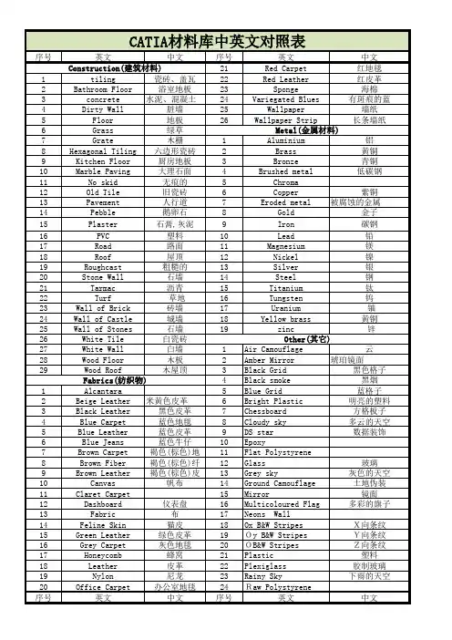
catia菜单中英文对照表File-文件Open Ctrl+O 打开Save Alt+S存盘Save as另存为Autosave File 自动存盘Hardcopy硬C opyScreen DumpPostScript Output Copy to Clipbord 复制到剪贴板Error Needle Report Dimension Report尺寸报表View Log File 查看注册文件Import Sketch 读入草图ExitAlt+X 退出Edit-编辑Layer Manager 层的管理Create Group G创建群组UngroupShift+U 删除群组Undo Hide Entity Ctrl+Z 撤消隐藏的实面RedoShift+Z 恢复Undo/Redo History 回退/恢复历史纪录Undo TransformCtrl+Shift+U 回退变换Repeat Last Operation Ctrl+Shift+Z 重复最后一次操作Delete All Ctrl+U删除所有Cut 剪切Copy 复制Paste粘贴Change Entity Name 更改实面名Empty Trash Preferance优先选择-系统设置Import/Export 输入/输出System系统Error Range Setting 错误范围的设置Restore Defaulte恢复默认值Enable Screen Updates 屏幕更新Open Command Line打开命令行Display-显示Entity Color 实体颜色(实体:点,线,面;这个功能基本上在站版面,层中可以操作,点云右键修改点色彩)Point点Display Ctrl+D点的显示模式Mosaic 点云多色显示,区分点云数目Scatter Polyline Polygon Mesh 三角网格这个指令自动把点云的显示方式改为圆状&多义线Gouraud -Shaded反光着色Hide All Ctrl+H隐藏全部Show All Ctrl+S显示全部Just Show Selected Ctrl+J只显示选择部分Remove Cloud Colors取消点云颜色Remove Cloud Errors取消点云错误部分Remove Cloud Curvature取消点云曲率Curve曲线Display Ctrl+Shift+D曲线的显示模式Mosaic不同颜色显示Show All Endpoints资料的头尾端显示Show All Directions显示方向Show All Knots显示节点Hide All Ctrl+Shift+H隐藏全部曲线Show All Ctrl+Shift+S显示全部曲线Just Show Selected Ctrl+Shift+J只显示选择部分Hide All 3D Curves隐藏全部3D曲线Show All 3D Curves显示全部3D曲线Hide All Surface Curves隐藏全部2D曲线Show All Surface Curves显示全部2D曲线Surface曲面Display Shift+D曲面的显示模式Mosaic合并Boundaries边界, 分界线Iso-LinesShaded渲染显示Show Shaded Model阴影显示Show Knots显示节点Hide All Shift+H隐藏全部Show All Shift+S显示全部Just Show Selected Shift+J只显示选择部分Coordinate System 坐标系Dimension尺寸Display显示尺寸Rescale Dimensions重新调整尺寸Show All显示全部Hide All隐藏全部Group组Display Alt+Shift+D显示Mosaic合并Hide All Alt+Shift+H隐藏全部Show All Alt+Shift+S显示全部Just Show Selected Alt+Shift+J只显示选择部分Label标签Display显示Hide All隐藏全部Show All显示全部Just Show Selected只显示选择部分Show Point Labels显示点标注Hide Point Labels隐藏点标注Plot矢量图Display显示Deviation背离Mosaic合并Hide All Plots Ctrl+Shift+M隐藏Hide All Color Maps Shift+M隐藏所有颜色图Name实面名Show All Names Shift+N显示全部名称Hide All Names Ctrl+Shift+N隐藏全部名称Show Selected Names只显示选择名称Put In No Show选择要隐藏的Toggle Show/No Show套选要隐藏的Show Only Selected 只显示选择部分Visibility可见性Make Invisible Ctrl+WMake All visible Shift+WMake Selected visible Ctrl+Shift+WSet Lights设置灯光Set Reflection Point设置镜像点Enhanced Display增强的显示Mirror Display对称显示Depth Cue等高线显示Perspactive Shift+V 透视图显示Field Of View空间显示Clipping Planes平面剪切View-视图Open Viewport打开视图Viewport Layout窗口布局Single Viewport Ctrl+1单视图Standard 4 Views Ctrl+4标准4视图Automotove View Arl+4自动视图Tile Views显示视图标题名Cascade Views层叠视图Define Views定义视图Top顶视图Bottom下视图Front前视图Back后视图Left左视图Right右视图Isometric等视图Restore User Views恢复用户视图Flip View视图掉换Save View 保存视图Delete View(s)删除视图Change View Name更改视图名称Show Grid显示网格Show Viewport Ruler显示视图标尺Align View to转换视图到非标准平面(以利作图)Direction矢量方向Cloud点云Curves曲线Surface表面Points点Coordinate System等轴系统Dimension尺寸Fill Screen Ctrl+F满屏幕显示Center Around Point确定视图中心点Rotate旋转WorldAround Center Of MessAround PointAround Vector5平移Along View PlaneAlong VectorZoom放大框选放大Magnify Box放大框Non-Proporttional Shift+ANon-Proporttional AspectToggle ProporttionReset Non-Proporttional Ctrl+Shift+AIn UpOut DownBy PercentageZoom FactorCreate-建立3D Curve3D 曲线3D B-Spline3D B-曲线Control Points控制点3D Polyline创建3D B样条Curve Primitive创建几何曲线Line直线Interactive Circle在目前视角绘制圆Arc圆弧Circle圆Ellipse椭圆Rectangle矩形Slot沟槽Polygon多边形Arc w/3 Points以3点建构圆弧Arc w/Center and 2 Points以2点+圆心建弧Circle w/3 Points3点建圆Circle w/Center and 2 Points2点+圆心建一圆Circle w/2 Points and Radius圆-3点加半径Surface Primitive 创建几何曲面Plane平面Cylinder圆柱面Sphere球面Cone圆锥面Surfacer w/4 Points平面-4点Plane w/3 Points平面-3点Cylinder w/Centers and Point圆柱面-中心,点Sphere w/4 Points球面-4点Sphere w/Centers and Point球面-中心,点Cone w/Centers and 2 Point圆锥面-中心,2点Plane Set平行平面设置Polygon Primitive创建网格Box盒状物Cylinder圆柱Cone圆锥Sphere球Points Ctrl+Shift+A点Annontation创建标注Text Label文本标注Dimension Label尺寸标注Set Point Labels设置点标注Delete Point Labels删除点标注Linear Dimension长度尺寸标注Angular Dimension角度尺寸标注Radial Dimension半径尺寸标注Modify Dimension修改尺寸标注Quadric Label二次曲面标注Error Needle Label公差标注Min/Max Needle LabelConstruction Line参考线Perpendicular Line垂直线Tangent Line相切线Infinite line无限直线Lines Between 2 Line角平分线Coordinate System坐标系统Create建立新的坐标系Form XformTranslate平移Rotate旋转Change Active更改激活Work Plane工作平面Create生成Settings设置Tolerance公差Point点Line直线Circle圆Ellipse椭圆Slot沟槽Retangle矩形Polygon多边形Plane平面Cylinder圆柱面Sphere球面Cone圆锥面Construct-构造Surface Form Cloud由点云构造曲面Uniform Surface Shift+F自由曲面Cylindrical Surface w/Curve点云+曲线形成圆柱面Interpolate Surface通过特定点的曲面Fit Plane拟合为平面Fit Cylinder合适的圆柱面Fit Sphere拟合为球面Fit Cone拟合为圆锥面Surface曲面Bi-Directional LoftLoft放样曲面Surface by Boundary由边界创建曲面Fit w/cloud and Curves点云和边界线拟合曲面Blend UV Curve Network U、V方向曲线生成曲面Surface of Revolution旋转曲面Plane Trimmed w/Curves由修剪曲线建立平面Swept Surface 扫掠曲面Ruled规则曲面Sweep扫掠曲面Extrude in Direction沿某方向延伸曲面Tube管状曲面Flange边缘Flange Surface曲面边缘,凸缘曲面Flange Surface (Tangent)曲面边缘(相切)Blend混和,桥接Curve混成曲线,桥接曲线Surface混成曲面,桥接曲面Fillet倒角Curve曲线倒角Arc w/Tangent to Curve与曲线相切的圆弧Dynamic Arc Fit动态弧形倒角Surface曲面倒角Curve to Surface曲线与曲面倒角Radius Between Curve设定半径范围的曲线倒角Offset偏移cloud点云的偏移Polygon Mesh网格面的偏移Curve曲线的偏移Surface曲面的偏移Cross Section点群资料撷取剖面资料STL Slices in Z截面为Z平面Simulate STL Slices模拟STL截面Cut STL Slices in Z w/SurfaceCloud Parallel Ctrl+B创建平行剖切截面Cloud Circular创建放射状剖切截面Cloud Interactive任意方面的剖切截面Cloud Curve Aligned沿着曲线方向剖切截面Curve Points对曲线切剖面Surface Points对曲面切剖面Surface Shift+B对曲面剖切产生的截面Surface Cloud同时对曲面和点云剖切Intersection相交线与交点With Curves曲线的相交点With Surfaces曲面相交线With Planes平面的交线Curve on Surface曲面上的曲线Surface Boundary to Curve曲面边界转为曲线Isoparametric Curve曲面边界转为2D曲线Project Curve to Surface投影曲线到曲面Interactive B-Spline建构B-Spline曲线Interactive Polyline建立波折线Curve Form Cloud曲线来之点云Fit Line建立直线Fit Arc建立圆弧Fit Circle建立圆Fit Ellipse建立椭圆Fit Retangle建立矩形Fit Slot建立沟槽Fit Polygon建立多边形Fit Curve建立曲线Fit PrimitiveUniform Curve Ctrl+Shift+F均匀曲线Tolerance Curve基于公差的曲线Uniform,Based on Curve按各点均匀形成曲线Tolerance,Based on Curve按公差形成曲线Interpolate Curve直接通过点云Bounding Circle计算点云边界圆Curve On CloudCurve Form Surface曲线来之曲面Surface Boundary to Curve曲面边界线Isoparametric Curve曲面向量线Surface Curve to 3D Curve曲面上之曲线Line Form Cylinder/Cone Axis建立圆柱或圆锥轴线Feature Line特征线Sharp Edges点云特征撷取Color Based按颜色提取点云Points点群Sample Polygon Centers提取三角形中心Average Point Clouds同两笔点云资料求平均点群Sample Curve由曲线产生点群project Curve on Cloud曲线投影到点云project Curve on Surface曲线投影到曲面Sample Surface由曲面取样产生点群Tool Compensate补偿工具Sample Plot提取图Polygons多边形Pick Polygons拾取多边形Pick Vertices for Polygons拾取多边形顶点Pick Points for Polygons拾取三角形的点Polygon Mesh多边形网格Polygonize Cloud点云多边形化Poly Form Surface多边形来自曲面Poly Form Surface ClosePoly Form Surface TolPoly Form Surface Tol ClosePolygonal T ooling多边形的加工Planar mold平面模型mold Form Curve模型来自曲线mold Form Surface模型来自曲面User Defined MoldCore DefinitionSignature ExtensionIce StructuresCreate Drain HoldModify-修改Control Points控制点Global Model点群整体不等比变形Clouds点云的整体调整Surfaces曲面的整体调整Rotate Surfaces旋转曲面Continuity连续性Create Constraint(s)建立曲线的约束关系Modify Constraint(s)修改约束关系Delete Constraint(s)删除约束关系Snap Curve to Curves固定曲线间的交点Match 2 Curves连接2个曲线Match Surface缝合两个曲面Match To Curves曲面连接至曲线上Match T Junction(3)缝合T形边界(3边)Match 4 Boundaries曲面与其他4个边连接曲面Match T Junction(4)缝合T形边界(4边)Make Edge Curvature Symmetric两曲面边界曲率一致Global Match配置球形Parameterization参数化Subdivide Polygons详细划分多边形Convert Order改变阶数Reparameterize Curve重新参数化曲线Insert/Remove Knot(s)插入/删除节点Insert/Remove Control Point(s)插入/删除控制点Redistribute Curve Knots重新分布曲线控制点位置Reparameterize Surface重新定义曲面控制点数Redistribute Surface Control Points重新分布控制点位置Insert Surface Knot插入曲面节点Remove Surface Knot删除曲面节点Convert Surface to Bezier转换成Bezier曲面Shape Control外形, 形状的控制Cloud Planarize点云平面化Change Curve Tangent Vector更改曲面切线方向Curve Planarize曲线的平面化Inflection Removal变形移动Pass curve through point经过曲线切线的点Curve curvature曲线曲率modify surface point更改曲面上的点Pass Surface Through Curve经过曲面切向的点Wrap Surface to Cloud限制曲线与点云距离Wrap Surface to Cloud w/Tolerance限制曲线与点云公差范围Multi-SurfaceWrp to CloudSurface Isoparm Planarize将曲面UV控制点移至特定平面Insert/Remove Curves Form Loft/UV Surface更改封闭曲面的起始位置Extend延伸Data Reduction减少数据Sample Uniform平均取样Chordal Deviation弦高取样Space Sampling距离取样Clean Curve清除曲线多余控制点Clean Surface清除曲面多余控制点Reduce Polygon Count简化多边形计算Reduce Polygon to Count减少多边形的数量Smooth光顺处理Scan点云光顺Scan Piecewise整体点群过滤光顺Scan Region区域进行光顺Scan Between Corners转角的光顺Polygons多边形B-spline B-样条曲线Extract抽取Circle-Select Points圈选点群Points With in Curves封闭的曲线圈选点群Points in Box方形框范围内的点云Subtract Cloud from Cloud点云相减Arbitrary Polygon Cut任意剪切多边形Slice均匀分割点群Scan Lines点云上提取扫描线Break Into XYZ Scans提取XYZ平面的扫描线Break Into Distinct Cloud以距离设定分离点群Surface Based Segmentation以曲面为准进行分割Merge合并Clouds+ Subtract Overlap点云合并,删除重叠部分Clouds点群资料相加Scan Cloud Form Scan点群扫描Surface合并曲面Snip剪断-用于曲线Snip polygon Mesh On Plane在平面上剪断多边形线Snip Curve(s)Ctrl+Shift+K剪断曲线Snip Surface Shift+K修剪曲面Split Surface分割曲面Trim修剪-用于曲面Polygon Mesh to Closed Curve封闭曲线向多边形Trim Surface Ctrl+T曲面边界修剪Trim w/Curve依曲线修剪曲面Unitrim Shift+T恢复修剪的曲线Remove Non Trim Curves移除非修剪的曲线Delete Unnecessary Outer Trims删除不必要的修剪曲线Boolean Extraction提取布尔曲线Cutting LineA AndB (Intersection)A OrB (union)A subB (subtraction)Scan Line扫描线Pick Delete Points Ctrl+Shift+P选取删除点云中的杂点Fill Gap补洞Remove Spikes删除尖点Set Opereting Distance设定操作距离Polygon Mesh网格化Vertex顶点Unpolygonize将三角网格回复成点群Delete a Vertex删除顶点Pick Delete Polygons拾取删除多边形Close关闭Close Shape关闭外形Close Selected Region关闭选择物体Close Rings关闭环形选择Join Cloud Vertices 接合点云最高点Cap ModelRepair Polygon Mesh修补多边形网格Remove Redundant移除多余的Remove Degenerate移除退化的Remove Overlaps移除过大的Split Into Distinct Objects分离Split Into Harmonized Objects分离Remove Multiple Edge Polys移除Remove Inconsistent Normal Polys移除Remove Long Polygons移除Direction矢量方向Sort Points by Direction依设定方向排序点Sort Points by Nearest最近似点排序点Reverse Scan Line Ctrl+R改变扫描线方向Reverse Polygon Mesh相反的多变形网格Reverse Polygon Normal将三角网格Normal方向反转Reverse Curve Direction Ctrl+Shift+R相反的曲线矢量方向Reverse Surface Normal Shift+R更改曲面着色方向Harmonize Polygon Normals协调多变形法线Harmonize Curve Direction协调曲线矢量方向Harmonize Surface Normals协调曲面法线Curve Aligned Scan Start Points将起始点定位至曲线上Change Scan Start Point更改扫描起始点Change Curve Start Point更改曲线的起始点Change Surface Start Point更改曲面起始边界Orient确定方向Interactive交互式旋转和平移Rotate旋转Translate平移Scale放大缩小Mirror镜像Transform Curve改变相对(绝对)特件坐标Send Home将物件送回原始位置Reset Home设定物件坐标位置Reset Object Axis重新设置物体坐标Align对齐Point Set to Point Set点对点定位Constrained Point Set to Point Set强制点对点定位321321对齐Iterative交互式对齐Mixed Mode混合模式对齐Constrained Mixed Mode强迫的混合对齐StepWise逐步式对齐SPT SPT对齐Best Fit最合适的对齐Constrained Best Fit强迫的最合适的对齐Align to Coordinate System坐标系统对齐Auto Align Cloud自动对齐点云Reapply坐标系重新对齐Inverse Matrix倒转矩阵Combine Matrices结合矩阵Identify Quadrics确定二次曲面Curve二次曲线Surface二次曲面Annotation注解Text Label文本标注Dimension Label尺寸标注Quadric Label二次曲面标注Error Needle Label公差标注Auto Arrange自动排列Evaluate-评估Control Plot曲线与曲面控制点分布图Tangent/Normal切线与法线Cloud Normals点云的法线Reset Cloud Normals重设点云的法线Curve Tangent曲线的切线Surface Normal曲面的法线Curvalure 曲率Cloud Curvalure点云曲率Curve Curvalure曲线曲率Curve Inflection曲线变形Surface Contours曲面的曲率分布图Surface Needles检验曲面的连续性Surface Flow流程, 流动Cloud Reflectance点云反射系数Reflection Lines Ctrl+E反射直线Highlight Lines Shift+E突出直线Specular Lines Ctrl+Shift+E镜向直线Cross Section Tangent Lines Arl+Shift+E部分截面切向直线Contour Mapping轮廓绘制Texture Mapping结构绘制Continuity连续性, 连贯性Curve to Curve Ctrl+Shift+O曲线对曲线检查Surface and Curve曲面对曲线检查Multi-Surface Shift+O曲面间的连续性检查Surface Gap/Angle Plot曲面间隙或角度检查Deviation偏差To Point曲线与点To Curve曲线与曲线To Surface曲面与曲面Cloud Characterisitics点云几何特征分析Straightness直线度Flatness平面度Circularity真圆度Cylindricity圆柱度Concentricity同心度Coaxiality同轴度Manufacturability可加工性Draft Angle Plot拔摸角度检查Tool Radius Plot半径工具Identify Redundant SurfacesPolygon Model多边形模型Verify Model检验模型Is Model BuilldableFind Self IntersectionsVolumeSurface AreaCenter of GravityFind Cut Area检查剪切范围Work VolumeFind Interference检查干涉Show Overhang RegionsInformation信息Object目标对象Coordinate System坐标系Database数据库Part零件,局部Alignment查询已对齐信息NedleMeasure-测量Cloud to检查点云Poly-Cloud Comparrison Ctrl+Q三角网格与点群的分析Cloud Difference点云差异Point Set Comparison点群与点群误差分析Many Point Comparison点群与点群误差分析Redisplay Cloud Defference重新显示检查点云结果Curve to检查曲线与点云差异Cloud Difference Ctrl+Shift+Q曲线和点云误差Curve Difference曲线差异Curve Min Distance点云与曲线的最短距离Redisplay Curve Defference重新显示检查曲线结果Surface to检查曲面与点云差异Cloud Difference Shift+Q曲面与点云差异Surface Difference曲面差异Redisplay Surface Defference重新显示检查曲面结果Distance 点之间距离Between Points点之间距离Point to Curve Closest点到曲线最短距离Point to Surface Closest点到曲面最短距离Angle/Tangent DirectionBetween Points点之间距离Direction Between Points测量两点间方向向量Angle Between Polygons测量两点间夹角Between Curve Tangents两曲线之切线夹角Curve Tangent Direction曲线切线方向Between Surface and Curve曲面与曲线之夹角Between Surface T angents曲面间切线平面夹角Surface Tangent Plane曲面上任一点的相切平面LocationPoint Location任一点坐标Surface LocationRadius Of Curvature3D Cloud Minimum点云最小曲率半径Cloud点云曲率半径Curve曲线Surface曲面Circumfernce使弯成圆形QuadricsPiercing Point尖点Enge Point末点Circle圆Slot沟槽Rectangle矩形Polygon多边形Plane平面Sphere球面Cylinder圆柱面Cone圆锥面Interactive交互式的Help-帮助Command Reference shift+F1命令介绍What's New in 11.1V11.1新增内容About Imageware关于Imageware。
TransmissionsTransmissions have to compromise on either ride comfort or efficiency, but a new approach to the dog engagement gearbox could improve both.With tightening emissions regulations, carmakers are not just confining their efforts to improving combustion and after-treatment. Many are finding that modern engines are so advanced that the benefits of some engine technologies are small compared to the huge development costs involved.It's important to look at the whole vehicle in order to improve emissions. As the second most expensive piece of kit in the car, the transmission is the logical next place to look.Of all transmission technologies, the manual gearbox is the most efficient; around 96percent of the energy that is put in comes out of the other end. But not everyone can drive one or wants to. Because you have to dip the clutch pedal, it's less comfortable to drive in heavy traffic. It makes the driver tired and the torque interruptions' head-nod effect on passengers can be wearing.The driver's clutch control and corresponding torque interruptions are also the manual's weak point. When accelerating up through the gearbox, each up-shift requires the driver to cut the torque momentarily by lifting the gas pedal and dipping the clutch. It may just take a second to complete the operation, but during this time the vehicle is losing speed and acceleration.At the opposite and of the spectrum is the traditional automatic. Its shift quality is good thanks to its torque converter, but efficiency is relatively poor despite recent advances. Because of this ,a lot of the current research is trying to find an efficient alternative to the conventional automatic.The main technologies are continuously variable transmissions (CVTs); dual clutch transmissions(DCTs) and automated manual transmissions(AMTs).They all offer different benefits over the conventional planetary automatic.The CVT uses a belt chain or toroidal shaped dish drive to vary an infinite number of gear ratios. It has improved efficiency and cost when compared to conventional automatics.Its advantage comes from its simplicitu. It consists of very few components; usually a rubber or metal-link belt; a hydraulically operated driving pulley, a mechanical torque-sensing driving pulley, microprocessors and some sensors.The transmissions works by varying the distance between the faces of the two main pulleys.The pulleys have V-shaped grooves in which the connecting belt rides. One side of the pulley is fixed axially; the other side moves, actuated by hydraulics.When actuatec, the cylinder can increase or reduce the amount of space between the two sides of the pulley. This allows the belt to ride lower or higher along the walls of the pulley, depending on driving conditions. This changes the gear ratio. A torodial-type design works in a similar way but runs on discs and power-rollers.The "stepless" nature of its design is CVT's biggest draw for automotive engineers. Because of this, a CVT can work to keep the engine in its optimum power range, thereby increasing efficiency and mileage. A CVT can convert every point on theengine's operating curve to a corresponding point on its own operating curve.The transmission is most popular with Japanese carmakers and Japanese supplier JATCO is a major producer. But in the US and Europe driving styles are different. Uptake has been slow despite Audi and other manufacturers having offered CVT otions on their ranges.The DCT is, in effect, two manual gearboxes coupled together. Gear shifts are made by switching from one clutch on one gearbox to another clutch on the other. The shift quality is equal to a conventional automatic, but slip, fluid drag and lydraulic losses in the system result in only slightly improved efficiency and acceleration over the conventional planetary automatic. Developing the control strategy is costly too."Recent advances in conventional automatic technology have weakened the argument to develop and set up production for CVT or DCT." says Bill Martin, managing director of transmission firm zeroshift. "Some carmakers have cancelled DCT projects because of the cost."The cheapest way to build an automatic is with an AMT. AMTs use actuators to replace the clutch pedal and gear stick of a conventional manual. They keep the high efficiency and acceleration of a manual gearbox, but the shift quality on some models is lacking. Torque interruptions and the head-nod effect are the most common complaint.so what is the alternative? There are always new ideas in transmissions, but Zeroshift says that its technology has efficiency benefits over a manual, delivering fuel economy improvements to city driving. Shift quality can also be equal to that of a refined automatic.Zeroshift's approach is an upgrade to the AMT. The synchromesh is replaced with an advanced dog enqaqement system.Dog engagement has been used for many years in motor sport to allow fast shifts. Conventional dog boxes are unsuitable for road use as the large spaces between the drive lugs or "dogs" create backlash, an uncomfortable shunt caused by the sudden change in torque direction.Zeroshift's technology solves this problem by adding a second set of drive dogs. It has also made each of the two sets of dogs only capable of transmitting torque in one or other opposing directions. "By controlling the engagement and disengagement of the two sets you can shift into the new gear befor disengaging the previous gear, "says Martin. "The shift quality is smoother than a typical modern six-speed automatic luxury car."The shift is instant and the torque is not interrupted.This philosophy is used for both up and down shifts."In conventional AMT there is an emissions spike during a shift due to the need to back off and reintroduce throttle, this is eliminated by going seamless, "says Martin. "This also reduces fuel consumption."It is a relative newcomer to the transmission sector, but the firm says that it is already attracting the attention of major European and US carmakers. The big draw is as a low-cost alternative to DCT, says Martin.Because the manual gearbox architecture is largely maintained, production costs and complexity are not greater than for a conventional AMT. Development of the controlsside is also considerably cheaper. Music to the ears of engineers trying to cut emissions and costs."Most of the carmakers have seen the system at least once," says Martion. "Some signed us immediately. Some have said not yet. None have said no. "That may be the clearest sign yet that when it comes to powertrain developments, carmakers are starting to focus on the transmission.HOW ZWROSHIFT WORKSThe hardware consists of two sets of bullets. mounted and actuated on two independent bullet rings. both sets of bullets run on the common hub, which is attached to the shaft with splines.Each bullet has a special profile. On one side they have an angled face for engagement. These are diagonally opposed, allowing the bullet to have a drive function for one gear and an overrun function for the other gear. The engagement faces taper backwards slightly to ensure the bullet latches onto the engaged gear under load.the opposite corners have a ramp, which pushes the bullet out of the previous gear once the new gear has been engaged.In neutral both bullet rings are positioned midway between the ratios. To select first gear, the bullets are moved into mesh with the engagement dogs.The bullets are actuated via shift forks conected to the shift actuators.The driving bullets lock first gear to the output shaft and transfer torque from the gearwheel onto the output shaft. The first gear overrun bullets are also moved into gear to lock the wheel to the output shaft in the opposite direction. This transfrs torque from the gearwheel onto the output shaft when the throttle closes and the engine overruns. This eliminates the backlash you'd expect from a dog engagement gearbox.To shift up with an open throttle, first gear's overrun bullets are unloaded and move in to engage second gear. This is followed by the previous driving ring which becomes unloaded when second gear is taken up.If the bullet is stopped from engaging fully-dog-face to dog-face-the second gear wheel opens an engagement window due to the relative speed difference. With the bullet pushed against the engagement dog compliance between the fork and actuator allows the stored energyto fire the bullet into the window.The first gear overrun bullets have now become the second gear drive bullets. As second gear takes over, the load is removed from the first gear drive bullets. These bullets are now no longer held by their retention angie and can be either moved out of gear by actuators or pushed out of gear by contact with the ramp face of the bullet.The first gear drive bullets then move across into engagement with second gear. In second gear, the roles of the bullets are reversed.Audi RoadjetAudi plans to add comfort, luxury and practicality without increasing emissionsThe Roadjet concept, first shown at Detroit in January 2006,indicates a number of technical directions that Audi going to take in the coming year. The firm is focusing on interior design, powertrain, chassis, electronics and safety innovations.These new directions will help Audi strengthen its position in the sub-luxury market that it previously had to itself. Audi has two main tactics to attract new customers in the US. It is breaking into the sports utility vehicle(SUV)and compact utility vehicle(CUV)markets.It also introduces new luxury and lifestyle features to strengthen its position in the US; sales there still lag behind those of BMW, Lexus and Mercedes-Benz. The recently launched Q7 off-road luxury vehicle is a late bid to capitalise on the SUV boom.In Europe, the carmaker's technical innovations such as aluminium construction, four-wheel-drive, and novel powertrain technologies have been successful. But if Audi wants to increase its US market share, it needs to innovate in those areas valued by American customers: comfort, luxury and practicality.Audi's designers have focused on this in the interior. They have devised a new wrap-around instrument panel shape to replace the more functional design in existing models. They have expanded the vehicle's multi-media interface (MMI)control system, used for cruise control, suspension, climate and entertainment separate controls. Combined with an upgraded climate system, occupants can set their own individual climate settings.Soft, warm, earthy colours are used in the Roadjet to create a feeling of well-being. The concept uses high quality functional materials: the upholstery is fine leather; the floor is neoprene. The space between the rear seats can house a range of optional equipment: the show car featured an espresso coffee machine. Storage boxes and baby carriers are more realistic alternatives.To enhance practicality, the rear seats slide backwards and forwards diagonally to increase shoulder and leg-room or rear load space. When the rear seats are in their most forward position, an oblique-facing child seat can be used behind the seats.Roadjet's load bay features an eletrically extending load floor to ease loading, offering unmerous lashing points to secure luggage items. The sliding seats and extending load floor are very likely to enter production on Audi's Q5 and A4 models.To heighten the sense of luxury, the concept uses a costly 1,000W Bang & Olufsen sound system with 14-speakers.This incorporates a "digital voice support" function that uses microphones and the car's speakers to pick up and amplify passengers' voices to ensure clear conversation even at high speeds.In a bid to improve road safety, convenience and traffic management, carmakers are working to common standards to develop a new in-car system to talk to other cars and roadside wireless olcal area networks. In traffic jams, bad weather or accident situations, cars send information to emergency services, other cars and traffic computers. The Roadjet concept featres previews such a system.The weight of all the new electronics and luxury equipment in this segment, combined with customers' growing demand for power is having a negative effect onexhaust emissions and fuel consumption. Audi is looking at sophisticated technical solutions to balance the equation.Roadjet's 3.2-litre gasoline direct injection engine is based on an existing engine but features a new fixed intake manifold with an integral vacuum reservoir to increase its output. This is combined with a two-stage cam operated variable valve lit technology to increase output.Despite the sports car performance, the Roadjet's overall fuel consumption is slightly lower than the current A4 Quattro 3.2FSI.The valve train technology, due to enter production later in 2006,lets the engine perform economically and smoothly during normal driving, switching automatically to more responsive, more powerful characteristics when the driver demands.Roadjet also has the first Audi application of speeddependent variable ratio dynamic steering for a stable highspeed motorway ride but with enhanced control on twisty country roads. Electronically-controlled variable rate dampers automatically adjust from soft and comfortable to firm and sporty to enhance safety and handling.Audi's engineers have electronically linked all of these systems to create three driver-selectable programmes: dynamic, comfort and sport. Each programme adjusts the dampers, steering, gearbox and engine eletronics to give different driving experiences.Roadjet's body styling marks a new direction for the carmaker.At 1.55m high with a wheelbase 4.7m long and 2.85m wide, the concept is roomy. The firm has used a combination of sharp feature lines and careully-sculpted concave-section doors to disguise the height. While the trademark LED tail lights are likely to enter production unchanged, steerable xenon gas discharge lights will replace the LEDs in the headlamps.Around the end of 2007 Audi will launch the Q5 CUV, based on the next A4 platform. Smaller and lighter than the Q7,it will be well placed to compete in the profitable CUV segment in the US. The Roadjet previews elements of the interior and exterior styling of this model.The Q5 will need to be more rugged to match the outdoor lifestyle image of the CUVsegment. At the same time, for the European market, the Roadjet's sharp style previews the next A4 model range, which may produce a new hatchback body in 2007 to join the conventional saloon and Avant estate. The dashboard and other new interior refinements are likely to spread across the rest of the Audi range over the next 24 months.变速器变速箱通常不得不在舒适性和效率之间做出选择,但一种新型的“犬牙啮合式”变速箱可以同时改善这两种性能。
CATIA模块中英⽂对照CATIA 模块中英⽂对照零件设计PDG :Part Design 装配设计ASD :Assembly Design 交互式⼯程绘图IDR :Interactive Drafting 创成式⼯程绘图GDR:Generative Drafting 结构设计STD :Structure Design 线架和曲⾯设计WSF:Wireframe and Surface 钣⾦设计SMD :SheetMetal Design 航空钣⾦设计ASL :Aerospace Sheetmetal Design 钣⾦加⼯设计SHP:SheetMetal Production 三维功能公差与标注设计FTA:3D Functional Tolerancing & Annotation模具设计MTD :Mold Tooling Design 阴阳模设计CCV :Core & Cavity Design 焊接设计WDG :Weld Design ⾃由风格曲⾯造型FSS:FreeStyle Shaper ⾃由风格曲⾯优化FSO:FreeStyle Optimizer 基于截⾯线的⾃由风格曲⾯造型FSP:FreeStyle Profiler基于草图的⾃由风格曲⾯造型FSK:FreeStyle Sketch Tracer创成式外形设计GSD:Generative Shape Design创成式曲⾯优化GSO:Generative Shape Optimizer汽车⽩车⾝接合ABF:Automotive Body In White Fastening数字化外形编辑DSE:Digitized Shape Editor汽车 A 级曲⾯造型ACA :Automotive Class A快速曲⾯重建QSR:Quick Surface Reconstruction创成式零件结构分析GPS :Generative Part Structural Analysis 创成式装配件结构分析GAS :Generative Assembly Structural Analysis 变形装配件公差分析TAA :Tolerance Analysis of Deformable Assembly Elfini 结构分析EST:Elfini Solver Verification 电路板设计CBD :Circuit Board Design 电⽓系统功能定义EFD :Electrical System Functional Definition 电⽓元件库管理员ELB :Electrical Library 电⽓线束安装EHI :Electrical Harness Installation 电⽓线束布线设计EWR :Electrical Wire Routing 电⽓线束展平设计EHF :Electrical Harness Flattening 管路和设备原理图设计PID :Piping & Instrumentation Diagrams HVAC 图表设计HVD :HVAC Diagrams电⽓连接原理图设计ELD :Electrical Connectivity Diagrams 系统原理图设计SDI :Systems Diagrams 管线原理图设计TUD :Tubing Diagrams波导设备原理图设计WVD :Waveguide Diagrams 系统布线设计SRT:Systems Routing 系统空间预留设计SSR:Systems Space Reservation 电⽓缆线布线设计ECR:Electrical Cableway Routing设备布置设计EQT :Equipment Arrangement 线槽与导管设计RCD:Raceway & Conduit Design波导设备设计WAV :Waveguide Design管路设计PIP:Piping Design管线设计TUB :Tubing DesignHVAC 设计HVA :HV AC Design⽀架设计HGR :Hanger Design结构初步布置设计SPL:Structure Preliminary Layout结构功能设计SFD:Structure Functional Design设备⽀撑结构设计ESS:Equipment Support Structures ⼚房设计PLOPlant Layout数控加⼯审查NCG:NC Manufacturing Review数控加⼯验证NVG :NC Manufacturing Verification2 轴半加⼯准备助⼿PMA :Prismatic Machining Preparation Assistant2 轴半加⼯PMG :Prismatic Machining3 轴曲⾯加⼯SMG :3 Axis Surface Machining多轴曲⾯加⼯MMG :Multi-Axis Surface Machining车削加⼯LMG :Lathe Machining⾼级加⼯AMG :Advanced Part MachiningSTL 快速成型STL :STL Rapid Prototyping知识⼯程顾问KWA :Knowledge Advisor知识⼯程专家KWE :Knowledge Expert产品⼯程优化PEO:Product Engineering Optimizer产品知识模板PKT :Product Knowledge Template 业务流程知识模板BKT :Business Process Knowledge Template 产品功能定义PFD:Product Function Definition 产品功能优化PFO:Product Function OptimizerDMU 漫游器DMN :DMNDMU NavigatorDMU 运动机构模拟KIN :DMU Kinematics SimulatorDMU 空间分析SPA:DMU Space AnalysisDMU 装配模拟FIT :DMU Fitting SimulatorDMU 优化器DMO :DMU OptimizerDMU ⼯程分析审查ANR :DMU Engineering Analysis ReviewDMU 空间⼯程助⼿SPE:DMU Space Engineering Assistant ⼈体模型构造器HBR :Human Builder⼈体模型测量编辑HME :Human Measurements Editor ⼈体姿态分析HPA:Human Posture Analysis⼈体⾏为分析HAA :Human Activity Analysis模块太多,下⾯我们就选择其中的⼀部分来介绍CATIA V5 主要应⽤产品包括:CATIA Mechanical Design 机械设计提供基于规则驱动的实体建模、混合建模以及钣⾦件设计,相关装配与集成化⼯程制图产品等。
CATIA模块中英文对照1.零件设计PDG:Part Design2.装配设计ASD:Assembly Design3.交互式工程绘图IDR:Interactive Drafting4.创成式工程绘图GDR:Generative Drafting5.结构设计STD:Structure Design6.线架和曲面设计WSF:Wireframe and Surface7.钣金设计SMD:SheetMetal Design8.航空钣金设计ASL:Aerospace Sheetmetal Design9.钣金加工设计SHP:SheetMetal Production10.三维功能公差与标注设计FTA:3D Functional Tolerancing &Annotation11.模具设计MTD:Mold Tooling Design12.阴阳模设计CCV:Core & Cavity Design13.焊接设计WDG:Weld Design14.自由风格曲面造型FSS:FreeStyle Shaper15.自由风格曲面优化FSO:FreeStyle Optimizer16.基于截面线的自由风格曲面造型 FSP:FreeStyle Profiler17.基于草图的自由风格曲面造型 FSK:FreeStyle Sketch Tracer18.创成式外形设计GSD:Generative Shape Design19.创成式曲面优化GSO:Generative Shape Optimizer20.汽车白车身接合ABF:Automotive Body In White Fastening21.数字化外形编辑DSE:Digitized Shape Editor22.汽车A级曲面造型 ACA:Automotive Class A23.快速曲面重建QSR:Quick Surface Reconstruction24.创成式零件结构分析GPS :Generative Part StructuralAnalysis25.创成式装配件结构分析GAS :Generative AssemblyStructural Analysis26.变形装配件公差分析TAA:Tolerance Analysis of DeformableAssembly27.Elfini 结构分析 EST:Elfini Solver Verification28.电路板设计CBD:Circuit Board Design29.电气系统功能定义EFD:Electrical System FunctionalDefinition30.电气元件库管理员ELB:Electrical Library31.电气线束安装EHI:Electrical Harness Installation32.电气线束布线设计EWR:Electrical Wire Routing33.电气线束展平设计EHF:Electrical Harness Flattening34.管路和设备原理图设计PID:Piping & InstrumentationDiagrams35.HVAC 图表设计HVD:HVAC Diagrams36.电气连接原理图设计ELD:Electrical Connectivity Diagrams37.系统原理图设计SDI:Systems Diagrams38.管线原理图设计TUD:Tubing Diagrams39.波导设备原理图设计WVD:Waveguide Diagrams40.系统布线设计SRT:Systems Routing41.系统空间预留设计SSR:Systems Space Reservation42.电气缆线布线设计ECR:Electrical Cableway Routing43.设备布置设计EQT:Equipment Arrangement44.线槽与导管设计RCD:Raceway & Conduit Design45.波导设备设计WAV:Waveguide Design46.管路设计PIP:Piping Design47.管线设计TUB:Tubing Design48.HVAC设计HVA:HVAC Design49.支架设计HGR:Hanger Design50.结构初步布置设计SPL:Structure Preliminary Layout51.结构功能设计SFD:Structure Functional Design52.设备支撑结构设计ESS:Equipment Support Structures53.厂房设计PLO Plant Layout54.数控加工审查NCG:NC Manufacturing Review55.数控加工验证NVG:NC Manufacturing Verification56.2轴半加工准备助手PMA:Prismatic Machining PreparationAssistant57.2轴半加工PMG:Prismatic Machining58.3轴曲面加工SMG:3 Axis Surface Machining59.多轴曲面加工MMG:Multi-Axis Surface Machining60.车削加工LMG:Lathe Machining61.高级加工AMG:Advanced Part Machining62.STL快速成型STL:STL Rapid Prototyping63.知识工程顾问KWA:Knowledge Advisor64.知识工程专家KWE:Knowledge Expert65.产品工程优化PEO:Product Engineering Optimizer66.产品知识模板PKT:Product Knowledge Template67.业务流程知识模板BKT:Business Process Knowledge Template68.产品功能定义PFD:Product Function Definition69.产品功能优化PFO:Product Function Optimizer70.DMU 漫游器DMN:DMNDMU Navigator71.DMU 运动机构模拟KIN:DMU Kinematics Simulator72.DMU 空间分析SPA:DMU Space Analysis73.DMU装配模拟FIT:DMU Fitting Simulator74.DMU优化器DMO:DMU Optimizer75.DMU工程分析审查ANR:DMU Engineering Analysis Review76.DMU空间工程助手SPE:DMU Space Engineering Assistant77.人体模型构造器HBR:Human Builder78.人体模型测量编辑HME:Human Measurements Editor79.人体姿态分析HPA:Human Posture Analysis80.人体行为分析HAA:Human Activity Analysis装配设计(ASS)CATIA装配设计可以使设计师建立并管理基于3D零件机械装配件。
车辆工程专业——外文文献翻译(中英文翻译)附录Ⅰ(原文)Modern cars is not a simple means of delivery, it is already "people, cars and the environment," the combination. As a car seat directly support the user's device, the car has no small importance of the components. The main function of car seats for the driver to provide ease of manipulation, comfortable, safe and easy fatigue of the driver seat. Seat design should also meet the following five basic requirements: the seat of the rational arrangement; Second, the seat shape to meet the body's physiological function; Third, the seat should have the regulatory agencies; Fourth, the vibration characteristics of a good seat; Five seats to be very safe and reliable; eat size of the installation location is important, it directly affects the user's convenience and comfort. Seating layout should reflect the requirements of ergonomics. Driver's seat is the most crucial seats. Its basic requirement is a reasonable layout and simple operation, that is, when the drivers take on the steering wheel, joystick and pedals for good accessibility. Because differences in European, American and Asian body in some countries is very wide car seat, car seat in some countries is relatively small. As the crowd the same area, there are differences between men and women, the tall and the small differences in driver's seatmust have regulatory agencies to meet most people's body. "Most people" concept, the car body design used a two-dimensional model, which according to the height of its total population is divided into different groups: Seat size of the installation location is important, it directly affects the user's convenience and comfort. Seating layout should reflect the requirements of ergonomics. Driver's seat is the most crucial seats. Its basic requirement is a reasonable layout and simple operation, that is, when the drivers take on the steering wheel, joystick and pedals for good accessibility. Because differences in European, American and Asian body in some countries is very wide car seat, car seat in some countries is relatively small. As the crowd the same area, there are differences between men and women, the tall and the small differences in driver's seat must have regulatory agencies to meet most people's body. "Most people" concept, the car body design used a two-dimensional model, which according to the height of its total population is divided into different groups: 5[%] (all 5[%] of drivers in the short stature than or equal to this size, the remaining 95[%] taller large); 95[%] (all 95[%] of drivers in the short stature than or equal to the size of the remaining 5[%] taller large). Applied in the automotive industry in the total range of between 5[%] and 95[%], that is, including the 90[%] crowd. For example, adjustable seats and pedals designed distance between the drivers as much as possible to adapt body, where women generally take 5[%] and 95[%] of male body model.Driver's seat on the steering wheel, joystick and pedals to take the body and determines the position, posture, seating arrangement by the position and shape of the design of the decision. Drivers to take the posture is not ideal or even lead to fatigue and strain. Therefore, Japan and major European and American design of the depot location has the basic drivers seat position, head, shoulders, arms, abdomen, legs and other reference data space, can not be arbitraryCar seats from the seat, back, dorsal support, headrests and other components, they have a surface shape, seat surface and backrest should be with the body shape curve of the back curve of a relaxed state match, after the seat occupant seated surface shape and the body pressure distribution in the muscles of the crew to make the most relaxed state, to support the lumbar spine, not because of poor circulation caused numbness, fatigue easily take a long time. Through the front seat up and down, backrest angle, head up and down positions, such as the limited front and rear adjustment, can make most people are comfortable. The spring seat seat vibration performance constitute the key. Tests show that vehicle is in motion even though the floor vibration, but the action of the spring seat, the seat is still possible to get good comfort, good performance if the spring, the comfort of the car will be relatively poor. At present, most holistic seat cushion foam urethane, which uses S-shaped coil springor springs from being buried in urethane foam, has a simple structure, low cost, noise-free advantages. Low-back seats for the car, the head is an attachment on the seat. As the speed increases, its growing importance of personal safety. Car in the event of rear-end collision, the impact of cars by the force behind the rapid moment forward, the inertia occupant's head is suddenly thrown back, cervical spine to withstand the acceleration forces to the large and easily hurt. With the head supporting and reduce the space of free movement of the head can reduce the impact of the cervical spine. 1998 Volvo (Volvo) car assembly WHIPS (Whiplash Protection System) rear-end collision occurs when the headrest and backrest can be made after the occupants moved at the same time effectively prevent cervical spine injury. The current car seat has seat belts, airbags together constitute the security of the crew. The strength of their own car seat, the reliability of the connection on the body, back strength and testing requirements are the industry standard, not just to do an installation up to the line. With modern technology, car seats are equipped pneumatic devices, air pump from the engine compartment is provided inside the seat back pressure chamber 4, respectively, to achieve the protection of the Ministry of the lumbar spine. Are divided into two parts back, the angle can be adjusted to make the waist and shoulder the same time close to the back, play a security role. Have built in the back of a computer-controlled electronic oscillator, and massage healtheffects.附录Ⅱ(译文)现代轿车已经不是一个单纯的运载工具,它已经是“人、汽车与环境”的组合体。
Level_1Level_2Level_3Level_4Level_5Level_61)┎CATPart 2)┠XY_Plane┠YZ_Plane┠ZX_Plane3)┠Axis_Systems 基准轴系┃┖Absolute_Axis_System 4)┠Parameters ┃┠Key_Parameter.15)┠Relations(关系式,建模中使用的公式、规则等)6)┠PartBody(CATPart 的主实体,表示对应的CATIA 零件。
CATIA 零件中不允许有多余的实体存在┃┠Main_Structure_build.1┃┠Boolean_Operation_1┃┃┖┃┠Boolean_Operation_2┃┃┖Assy_Feature_2┃┠Hole_Split_direction_1┃┠Hole_Split_direction_2┃┖…7)┠Master_Reference 元素集(Geometrical_Set),存放主要的参考元素集┃┠┃┠┃┃┠Reference.1┃┃┖…┃┠Model_2_Reference┃┖…8)┠Die_Direction(元素集(Geometrical_Set),存放零件的出模方向、冲压方向。
方向应由一段直线表示。
)9)┠Construction(元素集(Geometrical_Set),存放主体结构的操作)┃┠┃┃┠A_Join ┃┃┠A_Flange (元素集(Geometrical_Set),对A 面增加的翻边、结构所需的配合面等。
需要根据情况细分更多子集(Sub_Sets)┃┃┃┠ Flange_1┃┃┃┃ ┠Reference 元素集(Geometrical_Set),建立相应翻边配合面所引用的参考元素。
根据情况新命名元素集。
┃┃┃┃ ┠Basic_Curves ┃┃┃┃ ┠Block_Surfaces ┃┃┃┃ ┠Assy_Operation ┃┃┃┃ ┖Result ┃┃┃┖…┃┃┠┃┃┖A_Surface_Result ┃┠B_Surface ┃┃┠B_Join ┃┃┠┃┃┠Assy_Operation┃┃┖B_Surface_Result ┃┠Boundary ┃┠Feature_1┃┃┠Feature_Reference┃┃┠Basic_Curves┃┃┠Block_Surfaces┃┃┠Assy_Operation┃┃┖Result ┃┠Feature_2┃┠…┃┠Assy_Operation ┃┖Final_Result 10)┠Assy_Features┃┠Assy_Feature_1┃┃┠Feature_Reference ┃┃┖Feature_Operation ┃┠Assy_Feature_2┃┖…11)┠Cutouts┃┠Hole_Direction_1┃┠┃┖Hole_Direction_212)┠Datums┃┠A_Datums ┃┖…13)┠Tooling_Blocks┃┠Parting_Line ┃┠Sliders ┃┖…14)┖Free_Form_Analysis┖Draft_Analysis 元素集(Geometrical_Set),存放相应的翻边或配合面的最后结果。
CATIA 模块中英文对照零件设计PDG :Part Design 装配设计ASD :Assembly Design 交互式工程绘图IDR :Interactive Drafting 创成式工程绘图GDR:Generative Drafting 结构设计STD :Structure Design 线架和曲面设计WSF:Wireframe and Surface 钣金设计SMD :SheetMetal Design 航空钣金设计ASL :Aerospace Sheetmetal Design 钣金加工设计SHP:SheetMetal Production 三维功能公差与标注设计FTA:3D Functional Tolerancing & Annotation模具设计MTD :Mold Tooling Design 阴阳模设计CCV :Core & Cavity Design 焊接设计WDG :Weld Design 自由风格曲面造型FSS:FreeStyle Shaper 自由风格曲面优化FSO:FreeStyle Optimizer 基于截面线的自由风格曲面造型FSP:FreeStyle Profiler基于草图的自由风格曲面造型FSK:FreeStyle Sketch Tracer创成式外形设计GSD:Generative Shape Design创成式曲面优化GSO:Generative Shape Optimizer汽车白车身接合ABF:Automotive Body In White Fastening数字化外形编辑DSE:Digitized Shape Editor汽车 A 级曲面造型ACA :Automotive Class A快速曲面重建QSR:Quick Surface Reconstruction创成式零件结构分析GPS :Generative Part Structural Analysis 创成式装配件结构分析GAS :Generative Assembly Structural Analysis 变形装配件公差分析TAA :Tolerance Analysis of Deformable Assembly Elfini 结构分析EST:Elfini Solver Verification 电路板设计CBD :Circuit Board Design 电气系统功能定义EFD :Electrical System Functional Definition 电气元件库管理员ELB :Electrical Library 电气线束安装EHI :Electrical Harness Installation 电气线束布线设计EWR :Electrical Wire Routing 电气线束展平设计EHF :Electrical Harness Flattening 管路和设备原理图设计PID :Piping & Instrumentation Diagrams HVAC 图表设计HVD :HVAC Diagrams电气连接原理图设计ELD :Electrical Connectivity Diagrams 系统原理图设计SDI :Systems Diagrams 管线原理图设计TUD :Tubing Diagrams波导设备原理图设计WVD :Waveguide Diagrams 系统布线设计SRT:Systems Routing 系统空间预留设计SSR:Systems Space Reservation 电气缆线布线设计ECR:Electrical Cableway Routing设备布置设计EQT :Equipment Arrangement 线槽与导管设计RCD:Raceway & Conduit Design波导设备设计WAV :Waveguide Design管路设计PIP:Piping Design管线设计TUB :Tubing DesignHVAC 设计HVA :HV AC Design支架设计HGR :Hanger Design结构初步布置设计SPL:Structure Preliminary Layout结构功能设计SFD:Structure Functional Design设备支撑结构设计ESS:Equipment Support Structures 厂房设计PLOPlant Layout数控加工审查NCG:NC Manufacturing Review数控加工验证NVG :NC Manufacturing Verification2 轴半加工准备助手PMA :Prismatic Machining Preparation Assistant2 轴半加工PMG :Prismatic Machining3 轴曲面加工SMG :3 Axis Surface Machining多轴曲面加工MMG :Multi-Axis Surface Machining车削加工LMG :Lathe Machining高级加工AMG :Advanced Part MachiningSTL 快速成型STL :STL Rapid Prototyping知识工程顾问KWA :Knowledge Advisor知识工程专家KWE :Knowledge Expert产品工程优化PEO:Product Engineering Optimizer产品知识模板PKT :Product Knowledge Template 业务流程知识模板BKT :Business Process Knowledge Template 产品功能定义PFD:Product Function Definition 产品功能优化PFO:Product Function OptimizerDMU 漫游器DMN :DMNDMU NavigatorDMU 运动机构模拟KIN :DMU Kinematics SimulatorDMU 空间分析SPA:DMU Space AnalysisDMU 装配模拟FIT :DMU Fitting SimulatorDMU 优化器DMO :DMU OptimizerDMU 工程分析审查ANR :DMU Engineering Analysis ReviewDMU 空间工程助手SPE:DMU Space Engineering Assistant 人体模型构造器HBR :Human Builder人体模型测量编辑HME :Human Measurements Editor 人体姿态分析HPA:Human Posture Analysis人体行为分析HAA :Human Activity Analysis模块太多,下面我们就选择其中的一部分来介绍CATIA V5 主要应用产品包括:CATIA Mechanical Design 机械设计提供基于规则驱动的实体建模、混合建模以及钣金件设计,相关装配与集成化工程制图产品等。
中英文资料对照外文翻译文献综述附件1:外文翻译译文CATIA V5 的自动化CATIA V5的自动化和脚本:在NT 和Unix上:脚本允许你用宏指令以非常简单的方式计划CATIA。
CATIA 使用在MS –VBScript中(V5.x中在NT和UNIX3.0 )的共用部分来使得在两个平台上运行相同的宏。
在NT 平台上:自动化允许CATIA像Word/Excel或者Visual Basic程序那样与其他外用分享目标。
ATIA 能使用Word/Excel对象就像Word/Excel能使用CATIA 对象。
在Unix 平台上:CATIA将来的版本将允许从Java分享它的对象。
这将提供在Unix 和NT 之间的一个完美兼容。
CATIA V5 自动化:介绍(仅限NT)自动化允许在几个进程之间的联系:CATIA V5 在NT 上:接口COM:Visual Basic 脚本(对宏来说),Visual Basic 为应用(适合前:Word/Excel ),Visual Basic。
COM(零部件目标模型)是“微软“标准于几个应用程序之间的共享对象。
Automation 是一种“微软“技术,它使用一种解释环境中的COM对象。
ActiveX 组成部分是“微软“标准于几个应用程序之间的共享对象,即使在解释环境里。
OLE(对象的链接与嵌入) 意思是资料可以在一个其他应用OLE的资料里连结并且可以被编辑的方法(在适当的位置编辑)。
在VBScript,VBA和Visual Basic之间的差别:Visual Basic(VB) 是全部的版本。
它能产生独立的计划,它也能建立ActiveX 和服务器。
它可以被编辑。
VB中提供了一个补充文件名为“在线丛书“(VB的5.0)VBA(应用的Visual Basic)是一个Visual Basic的子集。
VBA是在诸如Word,Excel或CATIA的应用托管。
它提供了一个用编辑器,调试器,一个帮助对象查看器和完整的环境。
该<TOOLS>+< REFERENCE>菜单允许申报使用的对象库。
这使得可以访问结果和对象浏览器。
VBScript(Visual Basic脚本)是一个VBA的子集。
简单的语言解释基本法可以调用CATIA对象。
没有类型被使用。
系统动态地尝试调用方法和对象的属性。
(后期绑定通过他们的IDispatch接口调用对象)。
支持的语言CATIA 支持的语言是:CATScript :它是在V5的脚本语言,直到包容V5R7。
从V5R8,它变得过时,并建议使用MS VBScript 或MS VBA 。
MS VBScript:它是从V5R8首先使用的语言,唯一的解决方案是允许有一个在NT和UNIX可移植的脚本。
MS - VBScript不同于CATScript的是,这个概念在模糊地声明一个X变量为Y不存在。
MS -VBA:VBA是一个集成到CATIA和专用于VB的开发环境,但只在NT上。
MS - VBA不同于MS- VBScript的是编程的舒适性和实现简单图形界面的应用可能性。
面板ActiveX可以加入一个宏,但是只在NT 上。
如“Scripting.FileSystemObject“的其他服务被称为“CreateObject“,并只在NT中可用。
对象类型的声明记录在宏里(即使它不是在VBScript中使用),但它可以帮助你(在VB中与在NT上填写)计划你未来的应用。
CATIA V5的文件扩展名链接在CATIA V5中双击打开Windows资源管理器的“。
CATPart“文件。
在NT上,如果没有运行CATIA V5,它会自动启动。
CATIA V5的脚本功能在过程中的应用:这是在CATIA菜单的工具+宏中进行。
当宏运行时,CATIA停用。
你不能在两个调用间存储一个宏变量。
使用VBScript(微软)和VBA访问Windows NT和使用VBScript(Winsoft)访问Unix 。
输出过程中的应用(仅限NT)这基于自动化。
一个外部过程可以调用CATIA,创建或修改几何,解码,测量或试验CATIA。
CATIA仍然运行。
对于应用程序的每个动作,我们要检查是否CATIA 在良好的状态同步两个进程。
这种应用可以被发展在:Visual BasicWindows Scripting Host(VBScript,JScript),Windows Explorer HTML(VBScript,JScript)或者任何其他COM 应用。
在将来,V5自动化对象的Java 封装也将被提供。
这将促使在NT和基于Java的Unix上应用软件的开发,无论是在输入进程和输出进程。
宏进程我们在加工过程中调用它,因为该脚本的解释在与CATIA相同的过程里进行。
一个列表显示了可用的宏。
我们可以运行,编辑,重命名或删除现有的脚本,或创建一个新的。
上述小组建议的脚本库的列表是可以通过对库的一个窗口进行修改的。
利用CATIA的Visual Basic编辑器,我们可以编辑现有的宏或创建一个新的,插入图形形式,调试和运行VBA项目。
对话框的界面“工具+宏+宏...“允许选择一个宏(一个宏目录或一个VBA项目)或一个我们希望工作的文档库上。
从这个窗口,我们可以关闭已打开的库,开放一个库,或建立一个库。
库是按类型显示(目录,VBA项目)。
每库类型支持不同的语言。
VBA 只支持语言MS -VBA,当在一个目录里时,而在目录中,我们可以写在MS- VBScript或在CATScript。
录制宏该记录的VBA面板允许我们选择将记录的容器,使用的语言和宏的名字被记录。
所录制的脚本的语法是要根据不同的菜单中选择。
录制宏生成一个对应创建或修改对象的脚本再记录序列里。
停止录音后,我们可以存储,编辑重放这个脚本(称为宏)。
作为一项规则,记录一个宏可以帮助你学习如何编程的东西。
运行宏CATIA一启动,你就能执行宏:CNEXT -macro E:\Users\Macros\MacroToRun.CATScript。
你可以在批处理模式下启动宏来执行CATIA:CNEXT -batch -macroE:\Users\Macros\MacroToRun.CATScript。
你可以以交互方式从“宏“菜单中运行宏,你可以以交互方式从一个工具栏图标中运行宏。
来自另一个宏的宏的实行CATIA V5R9通过自动化功能提供能力从另一个宏中执行宏。
该功能可以让用户调用另一个脚本函数,在另一个宏库中,可能在另外一种脚本语言编写。
一个支持ENUM CATSys库类型是用来让开发人员介绍库那种要调用的函数包含所在。
(来自VBScript的例子)调用一个在确定的“E:\宏\数学”目录库里的新增功能,文件中的“整数Math.catvba“,一种将写成:Dim args2(1)args2(0) = 3args2(1) = 2Dim addResultaddResult = CATIA.SystemService.ExecuteScript ( "E:\Macros\Math", catScriptLibraryTypeDirectory, "IntegerMath.catvbs", "Add", args2 ) MsgBox addResult要调用一个PrintReport(),在一个确定的子的“E:\零件\ Part1.CATPart“V5文档库文件中的“Statistics.catvba“,一种将写成:Dim args()CATIA.SystemService.ExecuteScript"E:\Parts\Part1.CATPart",catScriptLibraryTypeDocument,"Statistics.catvbs", "PrintReport", args在工具条里增加一个作为命令的宏选择你要添加自定义的工具和宏命令标签页的宏,拖放宏的名称到你想要的工具栏,要选择另一个默认的图标,单击显示属性。
宏选项界面对话框“工具+选项+宏“的面板允许根据语言选择,编辑器将被推出来编辑宏,并且指定外部类库来考虑到脚本回放。
Whith新接口,运行时间意见的全部typelibsV5被自动考虑到。
除运行时间意见(例如优于)之外,这种选择只为宣布typelibs 服务。
运行输出进程方案(只在NT上)该脚本是在另一个运行在另一个进程中的应用程序中运行,例如:Visual Basic VBA(在 Excel 或Word),使用VBScript或JavaScript的WSH(Windows脚本主机),使用VBScript或JavaScript的HTML,CATIA可以从任何其他COM应用编写脚本。
从VBA或者Visual Basic运行输出进程VBA和Visual Basic提供有用的工具:对这来说,你可以声明所有由Dassault Systèmes提供的类型库文件(*. TLB)。
该类型库文件包含所有对象,方法和公开对象属性的声明。
类型定义允许的类型检查和“早期绑定“帮助完成给你所有属性和对象的方法,给你一个方法的参数类型。
浏览器对象描述了全部的出口对象。
下面是从VBA或Visual Basic来启动CATIA V5的语句。
如果CATIA已经运行:[...]Dim CATIA as ObjectSet CATIA = GetObject(,“CATIA.Application”)[...] 第一个参数。
为空白如果CATIA没运行:[...]Dim CATIA as ObjectSet CATIA = CreateObject(“CATIA.Application”)CATIA.Visible = True[...] 这个宏开始CATIA如果类型库INFITF.tbl被引用,我们可以作为INFITF.Application声明CATIA。
使用Windows脚本宿主来运行输出进程WSH支持用不同语言编写,如VBScript和JavaScript脚本。
你可以使用标准的编辑器来编写应用程序。
如果你的程序失败,你将可以使用Windows开发环境。
它可以在Visual Basic开发应用程序,然后评论类型和通过WSH运行它。
要运行一个VBScript(*. vbs的)或JavaScript(*. js)文件,你可以使用CScript或Wscript命令。
通常情况下,wscript.exe已经与这些扩展名相关。
在Windows脚本宿主的VBScript你可以在一个简单的ASCII文本文件中用扩展名“vbs“为Visual Basic脚本写一个VBScript程序。