机械毕业设计英文外文翻译371汽车系统
- 格式:doc
- 大小:68.50 KB
- 文档页数:15
毕业设计(论文)外文文献翻译文献、资料中文题目:汽车发动机文献、资料英文题目:AUTOMOTIVE ENGINE文献、资料来源:文献、资料发表(出版)日期:院(部):专业:机械设计制造及其自动化(车辆工程)班级:姓名:学号:指导教师:翻译日期: 2017.02.14译文题目: Automobile engineAUTOMOTIVE ENGINE1 Engine Classification and Overall MechanicsThe automobile engines can be classified according to: (1) cycles, (2) cooling system, (3) fuel system, (4) ignition method, (5) valve arrangement, (6) cylinder arrangement, (7) engine speed.Engines used in automobiles are the internal combustion heat engines. Theburning of gasoline inside the engine produces high pressure in the engine combustion chamber. This high pressure force piston to move, the movement is carried by connecting rods to the engine crankshaft. The crankshaft is thus made to rotate: therotary motion is carried through the power train to the car wheels so that they rotateand the car moves.The engine requires four basic systems to run (Fig. 2-1). Diesel engines requirethree of these systems. They are fuel system, ignition system (except diesel), lubricating system and cooling system. However, three other related systems are also necessary. These are the exhaust system, the emission-control system, and the starting system. Each performs a basic job in making the engine run.Fig. 2-1 The engine construction2 Engine Operating PrinciplesFig. 2-2 Engine termsThe term “stroke” is used to describe the movement of the piston within the cylinder. The movement of the piston from its uppermost position (TDC, top dead center) to its lowest position (BDC, bottom dead center) is called a stroke. The operating cycle may require either two or four strokes to complete. Most automobile engines operate on the four stroke cycle (Fig. 2-2).In four-stroke engine, four strokes of the piston in the cylinder are required to complete one full operating cycle. Each stroke is named after the action. It performs intake, compression, power, and exhaust in that order (Fig. 2-3).Intake stroke Compression stroke Power stroke Exhaust strokeFig. 2-3 Four-stroke-cycle gasoline engine1. The intake strokeThe intake stroke begins with the piston near the top of its travel. As the piston begins its descent, the exhaust valve closes fully, the intake valve opens and the volume of the combustion chamber begins to increase, creating a vacuum. As the piston descends, an air/fuel mixture is drawn from the carburetor into the cylinder through the intake manifold. The intake stroke ends with the intake valve close just after the piston has begun its upstroke.2. Compression strokeAs the piston is moved up by the crankshaft from BDC, the intake valve closes. The air/fuel mixture is trapped in the cylinder above the piston. Future piston travelcompresses the air/fuel mixture to approximately one-eighth of its original volume (approximately 8:1 compression ratio) when the piston has reached TDC. This completes the compression stroke.3. Power strokeAs the piston reaches TDC on the compression stroke, an electric spark is produced at the spark plug. The ignition system delivers a high-voltage surge of electricity to the spark plug to produce the spark. The spark ignites, or sets fire to, the air/fuel mixture. It now begins to burn very rapidly, and the cylinder pressure increases to as much as 3-5MPa or even more. This terrific push against the piston forces it downward, and a powerful impulse is transmitted through the connecting rod to the crankpin on the crankshaft. The crankshaft is rotated as the piston is pushed down by the pressure above it.4. Exhaust strokeAt the end of the power stroke the camshaft opens the exhaust valve, and the exhaust stroke begins. Remaining pressure in the cylinder, and upward movement of the piston, force the exhaust gases out of the cylinder. At the end of the exhaust stroke, the exhaust valve closes and the intake valve opens, repeating the entire cycle of events over and over again.3 Engine Block and Cylinder Head3.1 Engine BlockThe engine block is the basic frame of the engine. All other engine parts either fit inside it or fasten to it. It holds the cylinders, water jackets and oil galleries (Fig. 2-4). The engine block also holds the crankshaft, which fastens to the bottom of the block. The camshaft also fits in the block, except on overhead-cam engines. In most cars, this block is made of gray iron, or an alloy (mixture) of gray iron and other metals, such as nickel or chromium. Engine blocks are castings.Fig. 2-4 V6 engine blockSome engine blocks, especially those in smaller cars, are made of cast aluminum. This metal is much lighter than iron. However, iron wears better than aluminum. Therefore, the cylinders in most aluminum engines are lined with iron or steel sleeves. These sleeves are called cylinder sleeves. Some engine blocks are made entirely of aluminum.3.2 Cylinder SleevesCylinder sleeves are used in engine blocks to provide a hard wearing material for pistons and piston rings. The block can be made of one kind of iron that is light and easy to cast while the sleeves uses another that is better able to stand up wear and tear. There are two main types of sleeves: dry and wet (Fig. 2-5).Dry sleeve Wet sleeveFig. 2-5 Cylinder sleeve3.3 Cylinder HeadThe cylinder head fastens to the top of the block, just as a roof fits over a house. The underside forms the combustion chamber with the top of the piston. In-line engine of light vehicles have just one cylinder head for all cylinders; larger in-line engines can have two or more. Just as with engine blocks, cylinder heads can be made of cast iron or aluminum alloy. The cylinder head carries the valves, valve springs and the rockers on the rocker shaft, this part of valve gear being worked by the pushrods. Sometimes the camshaft is fitted directly into the cylinder head and operates on the valves without rockers. This is called an overhead camshaft arrangement.3.4 GasketThe cylinder head is attached to the block with high-tensile steel studs. The joint between the block and the head must be gas-tight so that none of the burning mixture can escape. This is achieved by using cylinder head gasket. Gaskets are also used to seal joins between the other parts, such as between the oil pan, manifolds, or water pump and the blocks.3.5 Oil PanThe oil pan is usually formed of pressed steel. The oil pan and the lower part of cylinder block together are called the crankcase; they enclose, or encase, the crankshaft. The oil pump in the lubricating system draws oil from the oil pan and sends it to all working parts in the engine. The oil drains off and run down into the pan. Thus, there is a constant circulation of oil between the pan and the working parts of the engine.4 Piston Assembly, piston rings , The piston pin ,Connecting Rods, Crankshafts And Flywheel4.1 PistonPiston rings and the piston pin are together called the piston assembly (Fig. 2-6).。

机械设计制造及其自动化毕业设计外文翻译英文原文名Automatic production line PLC control of automatic feeding station中文译名基于PLC的自动化生产线自动上料站的控制中文译文:自动化生产线自动上料站的PLC控制自动生产线是由工件传送系统和控制系统,将一组自动机床和辅助设备按照工艺顺序联结起来,自动完成产品全部或部分制造过程的生产系统,简称自动线。
二十世纪20年代,随着汽车、滚动轴承、小电机和缝纫机和其他工业发展,机械制造业开始出现在自动生产线,第一个是组合机床自动线。
在20世纪20年代,第一次出现在汽车工业流水生产线和半自动生产线,然后发展成自动生产线。
第二次世界大战后,在机械制造工业发达国家,自动生产线的数量急剧增加。
采用自动生产线生产的产品应该足够大,产品设计和技术应该是先进的、稳定的和可靠的,基本上保持了很长一段时间维持不变。
自动线用于大,大规模生产可以提高劳动生产率,稳定和提高产品质量,改善劳动条件,降低生产区域,降低生产成本,缩短生产周期,保证生产平衡、显著的经济效益。
自动生产线的一个干预指定的程序或命令自动操作或控制的过程,我们的目标是稳定、准确、快速。
自动化技术广泛用于工业、农业、军事、科学研究、交通运输、商业、医疗、服务和家庭,等自动化生产线不仅可以使人们从繁重的体力劳动、部分脑力劳动以及恶劣、危险的工作环境,能扩大人的器官功能,极大地提高劳动生产率,提高人们认识世界的能力,可以改变世界。
下面我说下它的应用范围:机械制造业中有铸造、锻造、冲压、热处理、焊接、切削加工和机械装配等自动线,也有包括不同性质的工序,如毛坯制造、加工、装配、检验和包装等的综合自动线。
加工自动线发展最快,应用最广泛的机械制造。
主要包括:用于处理盒、外壳、各种各样的部件,如组合机床自动线;用于加工轴、盘部分,由通用、专业化、或自动机器自动专线;转子加工自动线;转子自动线加工过程简单、小零件等。

附录附录A:英文文献与中文参考译文Automobile lamps adaptive development and reviewed in thispaperWith the development of the society and the continuous improvement of people's living standard, people on the requirements of the car has not only confined to performance, cost, but more and more requirements modern car safer, more environmental protection and more human. Car manufacturers are using more security, more environmental protection, design is more elegant and more province oil advantages to attract users. And at the same time, the new car should also must comply with the latest regulation, this has led to a new technology to get the application. As the big three auto safety thing, automobile lighting systems is one of the main active safety device, to the traditional automobile lighting system improvement and innovation also has become a hot spot in the study of the world automobile manufacturers.Therefore, how to make automotive lighting, driving more intelligent safety, more comfortable will become a very urgent and has the important practical significance of the subject. The traditional automobile lighting system mainly by the headlamps system, lightingsystem, signal car lighting system composed of three. With the progress of science and technology, traditional lighting system also experienced rapid progress, the corresponding traffic regulations also more and more perfect, headlamps system has gone through a kerosene lamp from the original to incandescent lamp, halogen lamp to now discharge lamp of the development process, the signal from the first portable lighting system development now widely applied to a kerosene lamp LED lights, the car lighting system is more and more kinds, more and more humane. But the actual use of traditional headlamps system, there are many problems. For example, the existing in the light of the close on lighting effect is very bad, especially in the urban traffic is more complex, often have a lot of drivers in the evening nearly light, and front fog lamps entirely open headlights; Vehicles in turning the corner, there are also lighting dark areas, the serious influence the driver on the corners on the judgment of the obstacles; Vehicles driving on a rainy day, the ground water reflected the headlights, produce light reflected glare, and so on. According to statistics, about 50% of the night accident happened without lighting facilities of the dark road, road lighting the poor, the greater the likelihood of accident. The night accounted for 33.1% of the total number of accidents accident (although driving at night accounts for only 1/5 of the rate during the day). The death toll is about 50%, compared to 12.4% during the day, the death rate from the accident, and the night for 33, 7%.The night and high death rate from multiple accident, and the reason is the eyesight of the driver and the lower than about 1/2. In addition the rain and fog will also make vision loss, glass and dirty water before not only reduced vision, still can make the distance distortion, which must be the attention of the driver. European car lighting research institutions in the once a special investigation, the results showed that the most wants to improve the European drivers of the wet weather is the lighting of the water came in second, a rural road lighting, the next is in turn corners lighting, highway lighting and urban lighting. The above of these problems, make developing a DuoZhong lighting function with the lighting system become necessary, and the function of switching, for security reasons, and must be automatically, thus, adaptive lighting system (ALS) will emerge as The Times require.At present, our country of all motor vehicle testing lines are equipped with headlamps inspection instrument, many experts and scholars are many important is also discussed in the paper. But, through the test of a station exploits the year two thousand Taiwan client survey analysis, vehicle headlamps a total qualified by only 45%, and these qualified vehicles and most of all foreign imports of the vehicle. Is Cause the situation are the main reasons: (1) the car factory products do not meet the national standards, and many of the car factory in just when examination is not qualified, headlamps But others just a factory qualified,but can't use how long and then aging, poor durability. (2) the most vehicles have the lack of units and the unit testing conditions and means, in the headlamps for maintenance, adjust the inaccurate even will not be adjusted. (3) because some leadership and drivers are subjective safety, think in car headlamp is not safety testing is very important, as long as the car brake performance that can assure safety, so for lack of maintenance and maintenance, headlamps on schedule maintenance and replacement cannot. (4) for most of the testing station can't test results in a timely and accurate to inform owners in testing station, in the practice of the factory also cannot fundamentally solve the problem. Make a complete year after year while still driving. This is CheJian departments and testing station should be improved and self perfection in. Automobile lamps when regular testing unqualified has the following three conditions: (1) the luminous intensity enough; (2) the bad light distribution, main beam axis skewed a quantity to exceed bid; (3) above two kinds of circumstances exist. The influence factors of its own problems have vehicles, such as: battery electric power system can't deficit or charging, test power system should be in charge state; Wire corrosion; Tire pressure is insufficient; Tire model about different; Adjustment screws to adjust the improper; Glass chimney on the dirt and headlamps quality problem. Also have a plenty of testing lines light inspection instrument installation accuracy and precision is unqualified, such as: light meter guide levelnessenough; Lines of the ground does not level off; When parking lights and the level of the instrument headlamp distance is not accurate; The longitudinal axis and inspection instrument vehicle guide not vertical; Instrument range is not accurate. These are caused by the unqualified headlamp factors, among which light inspection instrument because every year by special inspection agency calibration and qualified rear can use, therefore, the vehicle itself problem is the main reason. Vehicles unit, drivers and keep the repair personnel should be paid much attention to. Automobile lamps adaptive system to, corner sensor, abundant between front axle, control unit altitude sensor (ECU), and stepper motor of headlights. The basic principle is: when the automobile longitudinal swing, ECU acquisition sensor signal, through the internal control strategy, control the stepping motor rotation, thus promote headlamps turned the corresponding point of view, the main design to car longitudinal swing automobile lamps automatic adjust the Angle made drivers can have greater vision, reduce the driver's blind area, and avoiding risk, improve the security and stability of the car, this is very important.With more and more bright lights at night at the same time, improve visibility, how to avoid strong light onto the driveway, and to cause to car drivers of smooth shadow produces visual residual, losing the ability to identify and road conditions should be a body in a dangerous situation, socan effective improve the scope of the automotive lighting and Angle, is improve the night driving safety important issue. In addition to the steering wheel steering Angle according to the head lamp or so direction adjustment, reduce the parameters of the night vision blind Angle, but also must pay attention to the fluctuation level, because body vulnerable to load average or not is the way, ups and downs changes, resulting in body produce Angle, joint influence round the point of view of the project lamp. Pledge lamp too high, easy to make projection Angle to car drivers have dazzle light problem, when cast Angle is too low, the line of sight of driving itself could be a deficiency, or less than myself or others will be exposed to danger, so level (elevation Angle) control is necessary to maintain the stability of the lighting Angle. The head lamp level control from the early passive manual adjustment, half active into the present automatic type, half is active in a car the adjustment, automatic type is braking can also do real-time adjustments. Level automatically adjust the system based on the foundation of the original setting Angle, through the height difference sensors detect body under circumstances, calculate the light cast Angle offset, upwards or to adjust HID DengZu, maintain proper illuminate Angle. Advanced level automatically adjust the Angle projection system, will also make adjustment screw with speed.A high speed will further, in beam to real time see the greater distance road conditions, slow speed, lighting Angle to correction, avoid exposureto the driveway. Intelligent lamp is the lamp of the technology another development the mainstream. Adaptive headlights integrated operation speed, steering Angle and the degree of body forward has happened to adjust the parameters as the direction of the light source, so according to strictly can only be regarded as passively accept driver needs to adjust the lighting Angle, and active steering head lamp still had some differences. Released in 2008 and is expected to active the head lamp system, to receive more information to determine the appropriate again after the head lamp brightness and Angle projection, to the so-called active safety state. In addition to the existing wheel shaft height difference sensors, steering sensors,, the electronic control unit can order early to drive system, adjust the lighting Angle and light type.参考译文:汽车前照灯自适应发展综述随着社会的发展和人们生活水平的不断提高,人们对汽车的要求已不仅仅局限于性能,成本,而是越来越多的要求现代汽车更加安全,更加环保,更加人性化。

外文翻译英文原文Belt Conveying Systems Development of driving systemAmong the methods of material conveying employed,belt conveyors playa very important part in the reliable carrying of material over longdistances at competitive cost.Conveyor systems have become larger and more complex and drive systems have also been going through a process of evolution and will continue to do so.Nowadays,bigger belts require more power and have brought the need for larger individual drives as well as multiple drives such as 3 drives of 750 kW for one belt(this is the case for the conveyor drives in Chengzhuang Mine).The ability to control drive acceleration torque is critical to belt conveyors’performance.An efficient drive system should be able to provide smooth,soft starts while maintaining belt tensions within the specified safe limits.For load sharing on multiple drives.torque and speed control are also important considerations in the drive system’s design.Due to the advances in conveyor drive control technology,at present many more reliable.Cost-effective and performance-driven conveyor drive systemscovering a wide range of power are available for customers’ choices[1].1 Analysis on conveyor drive technologies1.1 Direct drivesFull-voltage starters.With a full-voltage starter design,the conveyor head shaft is direct-coupled to the motor through the gear drive.Direct full-voltage starters are adequate for relatively low-power, simple-profile conveyors.With direct fu11-voltage starters.no control is provided for various conveyor loads and.depending on the ratio between fu11-and no-1oad power requirements,empty starting times can be three or four times faster than full load.The maintenance-free starting system is simple,low-cost and very reliable.However, they cannot control starting torque and maximum stall torque;therefore.they arelimited to the low-power, simple-profile conveyor belt drives.Reduced-voltage starters.As conveyor power requirements increase,controlling the applied motor torque during the acceleration period becomes increasingly important.Because motor torque 1s a function of voltage,motor voltage must be controlled.This can be achieved through reduced-voltage starters by employing a silicon controlled rectifier(SCR).A common starting method with SCR reduced-voltage starters is to apply low voltage initially to take up conveyor belt slack.and then to apply a timed linear ramp up to full voltage and belt speed.However, this starting method will not produce constant conveyor belt acceleration.When acceleration is complete.the SCRs,which control the applied voltage to the electric motor. are locked in full conduction, providing fu11-line voltage to the motor.Motors with higher torque and pull—up torque,can provide better starting torque when combined with the SCR starters, which are available in sizes up to 750 KW.Wound rotor induction motors.Wound rotor induction motors are connected directly to the drive system reducer and are a modified configuration of a standard AC induction motor.By inserting resistance in series with the motor’s rotor windings.the modified motor control system controls motor torque.For conveyor starting,resistance is placed in series with the rotor for low initial torque.As the conveyor accelerates,the resistance is reduced slowly to maintain a constant acceleration torque.On multiple-drive systems.an external slip resistor may be left in series with the rotor windings to aid in load sharing.The motor systems have a relatively simple design.However, the control systems for these can be highly complex,because they are based on computer control of the resistance switching.Today,the majority of control systems are custom designed to meet a conveyor system’s particular specifications.Wound rotor motors are appropriate for systems requiring more than 400 kW .DC motor.DC motors.available from a fraction of thousands of kW ,are designed to deliver constant torque below base speed and constant kW above base speed to the maximum allowable revolutions per minute(r/min).with the majority of conveyor drives, a DC shunt wound motor is used.Wherein the motor’s rotating armature isconnected externally.The most common technology for controlling DC drives is a SCR device. which allows for continual variable-speed operation.The DC drive system is mechanically simple, but can include complex custom-designed electronics to monitor and control the complete system.This system option is expensive in comparison to other soft-start systems.but it is a reliable, cost-effective drive in applications in which torque,1oad sharing and variable speed are primary considerations.DC motors generally are used with higher-power conveyors,including complex profile conveyors with multiple-drive systems,booster tripper systems needing belt tension control and conveyors requiring a wide variable-speed range.1.2 Hydrokinetic couplingHydrokinetic couplings,commonly referred to as fluid couplings.are composed of three basic elements; the driven impeller, which acts as a centrifugal pump;the driving hydraulic turbine known as the runner and a casing that encloses the two power components.Hydraulic fluid is pumped from the driven impeller to the driving runner, producing torque at the driven shaft.Because circulating hydraulic fluid produces the torque and speed,no mechanical connection is required between the driving and driven shafts.The power produced by this coupling is based on the circulated fluid’s amount and density and the torque in proportion to input speed.Because the pumping action within the fluid coupling depends on centrifugal forces.the output speed is less than the input speed.Referred to as slip.this normally is between l% and 3%.Basic hydrokinetic couplings are available in configurations from fractional to several thousand kW .Fixed-fill fluid couplings.Fixed-fill fluid couplings are the most commonly used soft-start devices for conveyors with simpler belt profiles and limited convex/concave sections.They are relativelysimple,1ow-cost,reliable,maintenance free devices that provide excellent soft starting results to the majority of belt conveyors in use today.Variable-fill drain couplings.Drainable-fluid couplings work on the same principle as fixed-fill couplings.The coupling’s impellers are mounted on the AC motor and the runners on the driven reducer high-speed shaft.Housing mounted to the drive base encloses the working circuit.The coupling’s rotating casing containsbleed-off orifices that continually allow fluid to exit the working circuit into a separate hydraulic reservoir.Oil from the reservoir is pumped through a heat exchanger to a solenoid-operated hydraulic valve that controls the filling of the fluid coupling.To control the starting torque of a single-drive conveyor system,the AC motor current must be monitored to provide feedback to the solenoid control valve.Variable fill drain couplings are used in medium to high-kW conveyor systems and are available in sizes up to thousands of kW .The drives can be mechanically complex and depending on the control parameters.the system can be electronically intricate.The drive system cost is medium to high, depending upon size specified.Hydrokinetic scoop control drive.The scoop control fluid coupling consists of the three standard fluid coupling components:a driven impeller, a driving runner and a casing that encloses the working circuit.The casing is fitted with fixed orifices that bleed a predetermined amount of fluid into a reservoir.When the scoop tube is fully extended into the reservoir, the coupling is l00 percent filled.The scoop tube, extending outside the fluid coupling,is positioned using an electric actuator to engage the tube from the fully retracted to the fully engaged position.This control provides reasonably smooth acceleration rates.to but the computer-based control system is very complex.Scoop control couplings are applied on conveyors requiring single or multiple drives from l50 kW to 750 kW.1.3 Variable-frequency control(VFC)Variable frequency control is also one of the direct drive methods.The emphasizing discussion about it here is because that it has so unique characteristic and so good performance compared with other driving methods for belt conveyor. VFC devices Provide variable frequency and voltage to the induction motor, resulting in an excellent starting torque and acceleration rate for belt conveyor drives.VFC drives.available from fractional to several thousand(kW ), are electronic controllers that rectify AC line power to DC and,through an inverter, convert DC back to AC with frequency and voltage contro1.VFC drives adopt vector control or direct torque control(DTC)technology,and can adopt different operating speeds according to different loads.VFC drives can make starting or stallingaccording to any given S-curves.realizing the automatic track for starting or stalling curves.VFC drives provide excellent speed and torque control for starting conveyor belts.and can also be designed to provide load sharing for multiple drives.easily VFC controllers are frequently installed on lower-powered conveyor drives,but when used at the range of medium-high voltage in the past.the structure of VFC controllers becomes very complicated due to the limitation of voltage rating of power semiconductor devices,the combination of medium-high voltage drives and variable speed is often solved with low-voltage inverters using step-up transformer at the output,or with multiple low-voltage inverters connected in series.Three-level voltage-fed PWM converter systems are recently showing increasing popularity for multi-megawatt industrial drive applications because of easy voltage sharing between the series devices and improved harmonic quality at the output compared to two-level converter systems With simple series connection of devices.This kind of VFC system with three 750 kW /2.3kV inverters has been successfully installed in ChengZhuang Mine for one 2.7-km long belt conveyor driving system in following the principle of three-level inverter will be discussed in detail.2 Neutral point clamped(NPC)three-level inverter using IGBTsThree-level voltage-fed inverters have recently become more and more popular for higher power drive applications because of their easy voltage sharing features.1ower dv/dt per switching for each of the devices,and superior harmonic quality at the output.The availability of HV-IGBTs has led to the design of a new range of medium-high voltage inverter using three-level NPC topology.This kind of inverter can realize a whole range with a voltage rating from 2.3 kV to 4.1 6 kV Series connection of HV-IGBT modules is used in the 3.3 kV and 4.1 6 kV devices.The 2.3 kV inverters need only one HV-IGBT per switch[2,3].2.1 Power sectionTo meet the demands for medium voltage applications.a three-level neutral point clamped inverter realizes the power section.In comparison to a two-level inverter.the NPC inverter offers the benefit that three voltage levels can be supplied to the output terminals,so for the same output current quality,only1/4 of the switching frequency is necessary.Moreover the voltage ratings of the switches in NPC inverter topology will be reduced to 1/2.and the additional transient voltage stress on the motor can also be reduced to 1/2 compared to that of a two-level inverter.The switching states of a three-level inverter are summarized in Table 1.U.V and W denote each of the three phases respectively;P N and O are the dc bus points.The phase U,for example,is in state P(positive bus voltage)when theswitches S1u and S2uare closed,whereas it is in state N (negative bus voltage)when the switches S3u and S4uare closed.At neutral point clamping,the phase isin O state when either S2u or S3uconducts depending on positive or negative phasecurrent polarity,respectively.For neutral point voltage balancing,the average current injected at O should be zero.2.2 Line side converterFor standard applications.a l2-pulse diode rectifier feeds the divided DC-link capacitor.This topology introduces low harmonics on the line side.For even higher requirements a 24-pulse diode rectifier can be used as an input converter.For more advanced applications where regeneration capability is necessary, an active front.end converter can replace the diode rectifier, using the same structure as the inverter.2.3 Inverter controlMotor Contro1.Motor control of induction machines is realized by using a rotor flux.oriented vector controller.Fig.2 shows the block diagram of indirect vector controlled drive that incorporates both constant torque and high speed field-weakening regions where the PW M modulator was used.In this figure,the command flux is generated as function of speed.The feedback speed is added with the feed forward slip command signal . the resulting frequency signal is integrated and then the unit vectorsignals(cos and sin )are generated.The vector rotator generates the voltage and angle commands for the PW M as shown.PWM Modulator.The demanded voltage vector is generated using an elaboratePWM modulator.The modulator extends the concepts of space-vector modulation to the three-level inverter.The operation can be explained by starting from a regularly sampled sine-triangle comparison from two-level inverter.Instead of using one set of reference waveforms and one triangle defining the switchingand frequency, the three-level modulator uses two sets of reference waveforms Ur1and just one triangle.Thus, each switching transition is used in an optimal Ur2way so that several objectives are reached at the same time.Very low harmonics are generated.The switching frequency is low and thus switching losses are minimized.As in a two-level inverter, a zero-sequence component can be added to each set of reference waveform s in order to maximize the fundamental voltage component.As an additional degree of freedom,the position of the reference waveform s within the triangle can be changed.This can be used for current balance in the two halves of the DC-1ink.3 Testing resultsAfter Successful installation of three 750 kW /2.3 kV three-level inverters for one 2.7 km long belt conveyor driving system in Chengzhuang Mine.The performance of the whole VFC system was tested.Fig.3 is taken from the test,which shows the excellent characteristic of the belt conveyor driving system with VFC controller.Fig.3 includes four curves.The curve 1 shows the belt tension.From the curve it can be find that the fluctuation range of the belt tension is very smal1.Curve 2 and curve 3 indicate current and torque separately.Curve 4 shows the velocity of the controlled belt.The belt velocity have the“s”shape characteristic.A1l the results of the test show a very satisfied characteristic for belt driving system.4 ConclusionsAdvances in conveyor drive control technology in recent years have resulted in many more reliable.Cost-effective and performance-driven conveyor drive system choices for users.Among these choices,the Variable frequency control (VFC) method shows promising use in the future for long distance belt conveyor drives due to its excellent performances.The NPC three-level inverter using high voltage IGBTsmake the Variable frequency control in medium voltage applications become much more simple because the inverter itself can provide the medium voltage needed at the motor terminals,thus eliminating the step-up transformer in most applications in the past.The testing results taken from the VFC control system with NPC three.1evel inverters used in a 2.7 km long belt conveyor drives in Chengzhuang Mine indicates that the performance of NPC three-level inverter using HV-IGBTs together with the control strategy of rotor field-oriented vector control for induction motor drive is excellent for belt conveyor driving system.中文译文:带式输送机及其牵引系统在运送大量的物料时,带式输送机在长距离的运输中起到了非常重要的竞争作用。
Ignition SystemThe purpose of the ignition system is to create a spark that will ignite the fuel-air mixture in the cylinder of an engine. It must do this at exactly the right instant and do it at the rate of up to several thousand times per minute for each cylinder in the engine. If the timing of that spark is off by a small fraction of a second, the engine will run poorly or not run at all.The ignition system sends an extremely high voltage to the spark plug in each cylinder when the piston is at the top of its compression stroke. The tip of each spark plug contains a gap that the voltage must jump across in order to reach ground. That is where the spark occurs.The voltage that is available to the spark plug is somewhere between 20,000 volts and 50,000 volts or better. The job of the ignition system is to produce that high voltage from a 12 volt source and get it to each cylinder in a specific order, at exactly the right time.The ignition system has two tasks to perform. First, it must create a voltage high enough (20,000+) to across the gap of a spark plug, thus creating a spark strong enough to ignite the air/fuel mixture for combustion. Second, it must control the timing of that the spark so it occurs at the exact right time and send it to the correct cylinder.The ignition system is divided into two sections, the primary circuit and the secondary circuit. The low voltage primary circuit operates at battery voltage (12 to 14.5 volts) and is responsible for generating the signal to fire the spark plug at the exact right time and sending that signal to the ignition coil. The ignition coil is the component that converts the 12 volt signal into the high 20,000+ volt charge. Once the voltage is stepped up, it goes to the secondary circuit which then directs the charge to the correct spark plug at the right time.The BasicsBefore we begin this discussion, let’’s talk a bit about electricity in general. I know that this is Before we begin this discussion, letbasic stuff, but there was a time that you didn’’t know about this and there are people who need basic stuff, but there was a time that you didnto know the basics so that they could make sense of what follows.All automobiles work on DC (Direct Current). This means that current move in one direction, form the positive battery terminal to the negative battery terminal. In the case of the automobile, the negative battery terminal is connected by a heavy cable directly to the body and the engine block of the vehicle. The body and any metal component in contact with it is called the ground. This means that a circuit that needs to send current back to the negative side of the battery can be connected to any part of the vehicle’’s metal body or the metal engine block.be connected to any part of the vehicleA good example to see how this works is the headlight circuit. The headlight circuit consists of a wire that goes from the positive battery terminal to the headlight switch. Another wire goes from the headlight switch to one of two terminals on the headlight bulb. Finally, a third wire goes from a second terminal on the bulb to the metal body of car. When you switch the headlight on, you are connecting the wire from the battery with the wire to the headlamps allowing battery current to go directly to the headlamp bulbs. Electricity passes through the filaments inside the bulb, then out the other wire to the metal body. From there, the current goes back to the negative terminal of the battery completing the circuit. Once the current is flowing through this circuit, the filament inside the headlamp gets hot and glows brightly. Let there be light.Now, back to the ignition system, the basic principle of the electrical spark ignition system has not changed for over 75 years. What has changed is the method by which the spark is created and how it is distribute.Currently, there are three distinct types of ignition system. The mechanical ignition systemwas used prior to 1975. It was mechanical and electrical and used no electronics. By understanding these early system, it will be easier to understand the new electronic andcomputer controlled ignition system, so don’’t skip over it. The electronic ignition system started computer controlled ignition system, so donfinding its way to production vehicles during the early 70s and became popular when better control and improved reliability became important with the advent of emission controls. Finally, the distributor less ignition system became available in the mid 80s. This system was always computer controlled and contained no moving parts, so reliability was greatly improved. Most of these systems required no maintenance except replacing the spark plugs at intervals from 60,000 to over 100,000 miles.Let’’s take a detailed look at each system and see how they work.LetThe Mechanical Ignition SystemThe distributor is the nerve center of the mechanical ignition system and has two tasks to perform. First, it is responsible for triggering coil to generate a spark at the precise instant that it is required (which varies depending how fast the engine is turning and how much load it is under). Second, the distributor is responsible for directing that spark to the proper cylinder (which is why it is called a distributor).The circuit that powers the ignition system is simple and straight forward. When you insert the key in the ignition switch and turn the key to the Run position, you are sending current from the battery through a wire directly to the positive (+) side of the ignition coil. Inside the coil is a series of copper windings that loop around the coil over a hundred times before exiting out the negative (-) side of the coil. From there, a wire takes this current over to the distributor and is connected to a special on/off switch, called the points. When the points are closed, this current goes directly to ground. When current flows from the ignition switch, through the windings in the coil, then to ground, it builds a strong magnetic field inside the coil.The points are made up of a fixed contact point that is fastened to a plate inside the distributor, and a movable contact point mounted on the end of a spring loaded arm. The movable point rides on a 4, 6, or 8 lobe cam (depending on the number of cylinder in the engine) that is mounted on a rotating shaft inside the distributor. This distributor cam rotates in time with the engine, making one complete revolution for every two revolutions of the engine. As it rotates, the cam pushes the points open and closed. Every time the points open, the flow of current is interrupted through the coil, thereby collapsing the magnetic field and releasing a high voltage surge through the secondary coil windings. This voltage surge goes out the top of the coil and through the high-tension coil wire.Now, we have the voltage necessary to fire the spark plug, but we still have to get it to the correct cylinder. The coil wire goes from the coil directly to the distributor cap. Under the cap is a rotor that is mounted on top of the rotating shaft. The rotor has a metal strip on the top that is in constant contact with the center terminal of the distributor cap. It receives the high voltage surge from the coil wire and sends it to the other end of the rotor which rotates past each spark plug terminal inside the cap. As the rotor turns on the shaft, it sends the voltage to the correct spark plug wire, which in turn sends it to the spark plug. The voltage enters the spark plug at the terminal at the top and travels down the core until it reaches the tip. It then jumps across the tip of the spark plug, creating a spark suitable to ignite the fuel-air mixture inside that cylinder. The description I just provided is the simplified version, but should be helpful to visualize the process, but we left out a few things that make up this type of ignition system. For instance, we didn’’t talk about the condenser that is connected to the point, nor did we talk about the system didnto advance the timing. Let’’s take a look at each section and explore it in more detail.to advance the timing. LetThe Ignition SwitchThere are two separate circuits that go from the ignition switch to the coil. One circuit runs through a resistor in order to step down the voltage about 15% in order to protect the points from premature wear. The other circuit sends full battery voltage to the coil. The only time this circuit is used is during cranking. Since the starter draws a considerable amount of current to crank the engine, additional voltage is needed to power the coil. So when the key is turned to the spring-loaded start position, full battery voltage is used. As soon as the engine is running, the driver releases the key to the run position which directs current through the primary resistor to the coil.On some vehicles, the primary resistor is mounted on the firewall and is easy to replace if it fails. On other vehicles, most notably vehicles manufactured by GM, the primary resister is a special resister wire and is bundled in the wiring harness with other wires, making it more difficult to replace, but also more durable.The DistributorWhen you remove the distributor cap from the top of the distributor, you will see the points and condenser. The condenser is a simple capacitor that can store a small amount of current. When the points begin to open the current, flowing through the points looks for an alternative path to ground. If the condenser were not there, it would try to jump across the gap of the point as they begin to open. If this were allowed to happen, the points would quickly burn up and you would hear heavy static on the car radio. To prevent this, the condenser acts like a path to ground. It really is not, but by the time the condenser is saturated, the points are too far apart for the small amount of voltage to jump across the wide point gap. Since the arcing across the opening points is eliminated, the points last longer and there is no static on the radio from point arcing.The points require periodic adjustments in order to keep the engine running at peek efficiency. This is because there is a rubbing block on the points that is in contact with the cam and this rubbing block wears out over time changing he point gap. There are two ways that the points can be measured to see if they need an adjustment. One way is by measuring the gap between the open points when the rubbing block is on the high point of the cam. The other way is by measuring the dwell electrically. The dwell is the amount, in degrees of cam rotation that the points stay closed.On some vehicles, points are adjusted with the engine off and the distributor cap removed. A mechanic will loosen the fixed point and move it slightly, then retighten it in the correct position using a feeler gauge to measure the gap. On other vehicles, most notably GM cars, there is a window in the distributor where a mechanic can insert a tool and adjust the points using a dwell meter while the engine is running. Measuring dwell is much more accurate than setting the points with a feeler gauge.Points have a life expectancy of about 10,000 miles at which time have to be replaced. This is done during a routine major tune up, points, condenser, and the spark plugs are replaced, the timing is set and the carburetor is adjusted. In some cases, to keep the engine running efficiently, a minor tune up would be performed at 5,000 mile increments to adjust the point and reset the timing.Ignition CoilThe ignition coil is nothing more that an electrical transformer. It contains both primary and secondary winding circuit. The coil primary winding contains 100 to 150 turns of heavy copper wire. This wire must be insulated so that the voltage does not jump from loop to loop, shortingit out. If this happened, it could not create the primary magnetic field that is required. The primary circuit wire goes into the coil through the positive terminal, loops around the primary windings, then exits through the negative terminal.The coil secondary winding circuit contains 15,000 to 30,000 turns of fine copper wire, which also must be insulated from each other. The secondary windings sit inside the loops of the primary windings. To further increase the coils magnetic field the windings are wrapped around a soft iron core. To withstand the heat of the current flow, the coil is filled with oil which helps keep it cool.The ignition coil is the heart of the ignition system. As current flows through the coil a strong magnetic field is build up. When the current is shut off, the collapse of this magnetic field to the secondary windings induces a high voltage which is released through the large center terminal. This voltage is then directed to the spark plugs through the distributor.Ignition Timing The timing is set by loosening a hold-down screw and rotating the body of the distributor. Since the spark is triggered at the exact instant that the points begin to open, rotating the distributor body (which the point are mounted on) will change the relationship between the position and the position of the distributor cam, which is on the shaft that is geared to the engine rotation.While setting the initial or base timing is important, for an engine to run properly, the timing needs to change depending on the speed of the engine and the load that it is under. If we can move the plate that the points are mounted on, or we could change the position of the distributor cam in relation to the gear that drives it, we can alter the timing dynamically to suit the needs of the engine.Ignition Wires These cables are designed to handle 20,000 to more than 50,000 volts, enough voltage to toss you across the room if you were to be exposed to it. The job of the spark plug wires is to get that enormous power to the spark plug without leaking out. Spark plug wires have to endure the heat of a running engine as well as the extreme changes in the weather. In order to do their job, spark plug wires are fairly thick, with most of that thickness devoted to insulation with a very thin conductor running down the center. Eventually, the insulation will succumb to the elements and the heat of the engine and begins to harden, crack, dry out, or otherwise break down. When that happens, they will not be able to deliver the necessary voltage to the spark plug and a misfire will occur. That is what is meant by “Not running on all cylinders cylinders””. To correct this problem, the spark plug wires would have to be replaced.Spark plug wires are routed around the engine very carefully. Plastic clips are often used to keep the wires separated so that they do not touch together. This is not always necessary, especially when the wires are new, but as they age, they can begin to leak and crossfire on damp days causing hard starting or a rough running engine.Spark plug wires go from the distributor cap to the spark plugs in a very specific order. This is called the is called the ““firing order firing order”” and is part of the engine design. Each spark plug must only fire at the end of the compression stroke. Each cylinder has a compression stroke at a different time, so it is important for the individual spark plug wire to be routed to the correct cylinder.For instance, a popular V8 engine firing order is 1, 8, 4, 3, 6, 5, 7, 2. The cylinders are numbered from the front to the rear with cylinder #1 on the front-left of the engine. So the cylinders on the left side of the engine are numbered 1, 3, 5, 7while the right side are numbered 2, 4, 6, 8. On some engine, the right bank is 1, 2, 3, 4 while the left bank is 5, 6, 7, 8. A repairmanual will tell you the correct firing order and cylinder layout for a particular engine.The next thing we need to know is what direction the distributor is rotating in, clockwise or counter-clockwise, and which terminal on the distributor caps that #1 cylinder is located. Once we have this information, we can begin routing the spark plug wires.If the wires are installed incorrectly, the engine may backfire, or at the very least, not run on all cylinders. It is very important that the wires are installed correctly.Spark PlugsThe ignition system system’’s sole reason for being is to service the spark plug. It must provide sufficient voltage to jump the gap at the tip of the spark plug and do it at the exact right time, reliably on the order of thousands of times per minute for each spark plug in the engine.The modern spark plug is designed to last many thousands of miles before it requires replacement. These electrical wonders come in many configurations and heat ranges to work properly in a given engine. The heat range of a spark plug dictates whether it will be hot enough to burn off any residue that collects on the tip, but not so hot that it will cause pre-ignition in the engine. Pre-ignition is caused when a spark plug is so hot, that it begins to glow and ignite the fuel-air mixture prematurely, before the spark. Most spark plugs contain a resistor to suppress radio interference. The gap on a spark plug is also important and must be set before the spark plug is installed in the engine. If the gap is too wide, there may not be enough voltage to jump the gap, causing a misfire. If the gap is too small, the spark may be inadequate to ignite a lean fuel-air mixture also causing a misfire.The Electronic Ignition SystemThis section will describe the main differences between the early point & condenser systems and the newer electronic systems. If you are not familiar with the way an ignition system works in general, I strongly recommend that you first read the previous section The Mechanical Ignition System.In the electronic ignition system, the points and condenser were replaced by electronics. On these systems, there were several methods used to replace the points and condenser in order to trigger the coil to fire. One method used a metal wheel with teeth, usually one for each cylinder. This is called an armature. A magnetic pickup coil senses when a tooth passes and sends a signal to the control module to fire the coil.Other systems used an electric eye with a shutter wheel to send a signal to the electronics that it was time to trigger the coil to fire. These systems still need to have the initial timing adjusted by rotating the distributor housing.The advantage of this system, aside from the fact that it is maintenance free, is that the control module can handle much higher primary voltage than the mechanical point. V control module can handle much higher primary voltage than the mechanical point. Voltage can oltage can even be stepped up before sending it to the coil, so the coil can create a much hotter spark, on the order of 50,000 volts that is common with the mechanical systems. These systems only have a single wire from the ignition switch to the coil since a primary resistor is not longer needed. On some vehicles, this control module was mounted inside the distributor where the points used to be mounted. On other designs, the control module was mounted outside the distributor with external wiring to connect it to the pickup coil. On many General Motors engines, the control module was inside the distributor and the coil was mounted on top of the distributor for a one piece unitized ignition system. GM called it high energy ignition or HEI for short.The higher voltages that these systems provided allow the use of a much wider gap on the spark plugs for a longer, fatter spark. This larger sparks also allowed a leaner mixture for betterfuel economy and still insure a smooth running engine.The early electronic systems had limited or no computing power, so timing still a centrifugal and vacuum advance built into the distributor.On some of the later systems, the inside of the distributor is empty and all triggering is performed by a sensor that watches a notched wheel connected to either the crankshaft or the camshaft. These devices are called crankshaft position sensor or camshaft position sensor. In these systems, the job of the distributor is solely to distribute the spark to the correct cylinder through the distributor cap and rotor. The computer handles the timing and any timing advance necessary for the smooth running of the engine.The Distributor Ignition SystemNewer automobiles have evolved from a mechanical system (distributor) to a completely solid state electronic system with no moving parts. These systems are completely controlled by the on-board computer. In place of the distributor, there are multiple coils that each serves one or two spark plugs. A typical 6 cylinder engine has 3 coils that are mounted together in a coil pack””. A spark plug wire comes out of each side of the individual coil and goes to the “packappropriate spark plug. The coil fires both spark plugs at the same time. One spark plug fires on the compression stroke igniting the fuel-air mixture to produce power while the other spark plug fires on the exhaust stroke and does nothing. On some vehicles, there is an individual coil for each cylinder mounted directly on top of the spark plug. This design completely eliminates the high tension spark plug wires for even better reliability. Most of these systems use spark plugs that are designed to last over 100,000 miles, which cuts down on maintenance costs.参考文献:[1] 王欲进,张红伟汽车专业英语[M]. 北京:北京大学出版社,中国林业出版社,2007.8,55—67点火系统点火系统的作用是产生点燃发动机气缸里可燃混合物的火花。
Ultrasonic ranging system designPublication title: Sensor Review. Bradford: 1993.Vol.ABSTRACT: Ultrasonic ranging technology has wide using worth in many fields, such as the industrial locale, vehicle navigation and sonar engineering. Now it has been used in level measurement, self-guided autonomous vehicles, fieldwork robots automotive navigation, air and underwater target detection, identification, location and so on. So there is an important practicing meaning to learn the ranging theory and ways deeply. To improve the precision of the ultrasonic ranging system in hand, satisfy the request of the engineering personnel for the ranging precision, the bound and the usage, a portable ultrasonic ranging system based on the single chip processor was developed.Keywords: Ultrasound, Ranging System, Single Chip Processor1. IntroductiveWith the development of science and technology, the improvement of people’s standard of living, speeding up the development and construction of the city. Urban drainage system have greatly developed their situation is construction improving. However, due to historical reasons many unpredictable factors in the synthesis of her time, the city drainage system. In particular drainage system often lags behind urban construction. Therefore, there are often good building excavation has been building facilities to upgrade the drainage system phenomenon. It brought to the city sewage, and it is clear to the city sewage and drainage culvert in the sewage treatment system.Co mfort is very important to people’s lives. Mobile robots designed to clear the drainage culvert and the automatic control system Free sewage culvert clear guarantee robots, the robot is designed to clear the culvert sewage to the core. Control system is the core component of the development of ultrasonic range finder. Therefore, it is very important to design a good ultrasonic range finder.2. A principle of ultrasonic distance measurementThe application of AT89C51:SCM is a major piece of computer components are integrated into the chip micro-computer. It is a multi-interface and counting on the micro-controller integration, and intelligence products are widely used in industrial automation. and MCS-51 microcontroller is a typical and representative.Microcontrollers are used in a multitude of commercial applications such as modems, motor-control systems, air conditioner control systems, automotive engine and among others. The high processing speed and enhanced peripheral set of these microcontrollers make them suitable for such high-speed event-based applications. However, these critical application domains also require that these microcontrollers are highly reliable. The high reliability and low market risks can be ensured by a robust testing process and a proper tools environment for the validation of these microcontrollers both at the component and at the system level. Intel Plaform Engineering department developed an object-oriented multi-threaded test environment for the validation of its AT89C51 automotive microcontrollers. The goals of this environment was not only to provide a robust testing environment for the AT89C51 automotive microcontrollers, but to develop an environment which can be easily extended and reused for the validation of several other future microcontrollers. The environment was developed in conjunction with Microsoft Foundation Classes(AT89C51).1.1 Features* Compatible with MCS-51 Products* 2Kbytes of Reprogrammable Flash MemoryEndurance: 1,000Write/Erase Cycles* 2.7V to 6V Operating Range* Fully Static operation: 0Hz to 24MHz* Two-level program memory lock* 128x8-bit internal RAM* 15programmable I/O lines* Two 16-bit timer/counters* Six interrupt sources*Programmable serial UART channel* Direct LED drive output* On-chip analog comparator* Low power idle and power down modes1.2 DescriptionThe AT89C2051 is a low-voltage, high-performance CMOS 8-bit microcomputer with 2Kbytes of flash programmable and erasable read only memory (PEROM). The device is manufactured using Atmel’s high density nonvolatile memory technology and is compatible with the industry standard MCS-51 instruction set and pinout. By combining a versatile 8-bit CPU with flash on a monolithic chip, the Atmel AT89C2051 is a powerful microcomputer which provides a highly flexible and cost effective solution to many embedded control applications.The AT89C2051 provides the following standard features: 2Kbytes of flash,128bytes of RAM, 15 I/O lines, two 16-bit timer/counters, a five vector two-level interrupt architecture, a full duplex serial port, a precision analog comparator, on-chip oscillator and clock circuitry. In addition, the AT89C2051 is designed with static logicfor operation down to zero frequency and supports two software selectable power saving modes. The idle mode stops the CPU while allowing the RAM, timer/counters, serial port and interrupt system to continue functioning. The power down mode saves the RAM contents but freezer the oscillator disabling all other chip functions until the next hardware reset.1.3 Pin Configuration1.4 Pin DescriptionVCC Supply voltage.GND Ground.Prot 1Prot 1 is an 8-bit bidirectional I/O port. Port pins P1.2 to P1.7 provide internal pullups. P1.0 and P1.1 require external pullups. P1.0 and P1.1 also serve as the positive input (AIN0) and the negative input (AIN1), respectively, of the on-chip precision analog comparator. The port 1 output buffers can sink 20mA and can drive LED displays directly. When 1s are written to port 1 pins, they can be used as inputs. When pins P1.2 to P1.7 are used as input and are externally pulled low, they will source current (IIL) because of the internal pullups.Port 3Port 3 pins P3.0 to P3.5, P3.7 are seven bidirectional I/O pins with internal pullups. P3.6 is hard-wired as an input to the output of the on-chip comparator and is not accessible as a general purpose I/O pin. The port 3 output buffers can sink 20mA. When 1s are written to port 3 pins they are pulled high by the internal pullups and can be used as inputs. As inputs, port 3 pins that are externally being pulled low will source current (IIL) because of the pullups.Port 3 also serves the functions of various special features of the AT89C2051 as listed below.1.5 Programming the FlashThe AT89C2051 is shipped with the 2 Kbytes of on-chip PEROM code memory array in the erased state (i.e., contents=FFH) and ready to be programmed. The code memory array is programmed one byte at a time. Once the array is programmed, to re-program any non-blank byte, the entire memory array needs to be erased electrically.Internal address counter: the AT89C2051 contains an internal PEROM address counter which is always reset to 000H on the rising edge of RST and is advanced applying a positive going pulse to pin XTAL1.Programming algorithm: to program the AT89C2051, the following sequence is recommended.1. power-up sequence:Apply power between VCC and GND pins Set RST and XTAL1 to GNDWith all other pins floating , wait for greater than 10 milliseconds2. Set pin RST to ‘H’ set pin P3.2 to ‘H’3. Apply the appropriate combination of ‘H’ or ‘L’ logic to pins P3.3, P3.4, P3.5,P3.7 to select one of the programming operations shown in the PEROM programming modes table.To program and Verify the Array:4. Apply data for code byte at location 000H to P1.0 to P1.7.5.Raise RST to 12V to enable programming.5. Pulse P3.2 once to program a byte in the PEROM array or the lock bits. The byte-write cycle is self-timed and typically takes 1.2ms.6. To verify the programmed data, lower RST from 12V to logic ‘H’ level and set pins P3.3 to P3.7 to the appropriate levels. Output data can be read at the port P1 pins.7. To program a byte at the next address location, pulse XTAL1 pin once to advance the internal address counter. Apply new data to the port P1 pins.8. Repeat steps 5 through 8, changing data and advancing the address counter for the entire 2 Kbytes array or until the end of the object file is reached.9. Power-off sequence: set XTAL1 to ‘L’ set RST to ‘L’Float all other I/O pins Turn VCC power off2.1 The principle of piezoelectric ultrasonic generatorPiezoelectric ultrasonic generator is the use of piezoelectric crystal resonators to work. Ultrasonic generator, the internal structure as shown, it has two piezoelectric chip and a resonance plate. When it’s two plus pulse signal, the frequency equal to the intrinsic piezoelectric oscillation frequency chip, the chip will happen piezoelectric resonance, and promote the development of plate vibration resonance, ultrasound is generated. Conversely, it will be for vibration suppression of piezoelectric chip, the mechanical energy is converted to electrical signals, then it becomes the ultrasonic receiver.The traditional way to determine the moment of the echo’s arrival is based on thresholding the received signal with a fixed reference. The threshold is chosen well above the noise level, whereas the moment of arrival of an echo is defined as the first moment the echo signal surpasses that threshold. The intensity of an echo reflecting from an object strongly depends on the object’s nature, size and distance from the sensor. Further, the time interval from the echo’s starting point to the moment when it surpasses the threshold changes with the intensity of the echo. As a consequence, a considerable error may occur even two echoes with different intensities arriving exactly at the same time will surpass the threshold at different moments. The stronger one will surpass the threshold earlier than the weaker, so it will be considered as belonging to a nearer object.2.2 The principle of ultrasonic distance measurementUltrasonic transmitter in a direction to launch ultrasound, in the moment to launch the beginning of time at the same time, the spread of ultrasound in the air, obstacles on his way to return immediately, the ultrasonic reflected wave received by the receiverimmediately stop the clock. Ultrasound in the air as the propagation velocity of 340m/s, according to the timer records the time t, we can calculate the distance between the launch distance barrier(s), that is: s=340t / 23. Ultrasonic Ranging System for the Second Circuit DesignSystem is characterized by single-chip microcomputer to control the use of ultrasonic transmitter and ultrasonic receiver since the launch from time to time, single-chip selection of 875, economic-to-use, and the chip has 4K of ROM, to facilitate programming.3.1 40 kHz ultrasonic pulse generated with the launchRanging system using the ultrasonic sensor of piezoelectric ceramic sensorsUCM40, its operating voltage of the pulse signal is 40kHz, which by the single-chip implementation of the following procedures to generate.puzel: mov 14h, # 12h; ultrasonic firing continued 200msHere: cpl p1.0; output 40kHz square wavenop;nop;nop;djnz 14h, here;retRanging in front of single-chip termination circuit P1.0 input port, single chip implementation of the above procedure, the P1.0 port in a 40kHz pulse output signal, after amplification transistor T, the drive to launch the first ultrasonic UCM40T, issued 40kHz ultrasonic pulse, and the continued launch of 200ms. Ranging the right and the left side of the circuit, respectively, then input port P1.1 and P1.2, the working principle and circuit in front of the same location.3.2 Reception and processing of ultrasonicUsed to receive the first launch of the first pair UCM40R, the ultrasonic pulse modulation signal into an alternating voltage, the op-amp amplification IC1A and after polarization IC1B to IC2. IC2 is locked loop with audio decoder chip LM567, internal voltage-controlled oscillator center frequency of f0=1/1.1R8C3, capacitor C4 determinetheir target bandwidth. R8-conditioning in the launch of the high jump 8 feet into a low-level, as interrupt request signals to the single-chip processing.Ranging in front of single-chip termination circuit output port INT0 interrupt the highest priority, right or left location of the output circuit with output gate IC3A access INT1 port single-chip, while single-chip P1.3 and P1.4 received input IC3A, interrupted by the process to identify the source of inquiry to deal with, interrupt priority level for the first left right after. Part of the source code is as follows:Receivel: push pswpush accclr ex1; related external interrupt 1jnb p1.1, right; P1.1 pin to 0, ranging from right to interrupt service routine circuitjnb p1.2, left; P1.2 pin to 0, to the left ranging circuit interrupt service routinereturn: SETB EX1; open external interrupt 1pop accpop pswretiright: …; right location entrance circuit interrupt service routineAjmp Returnleft: …; left ranging entrance circuit interrupt service routineAjmp Return3.3 The calculation of ultrasonic propagation timeWhen you start firing at the same time start the single-chip circuitry within the timer T0, the use of timer counting function records the time and the launch of ultrasonic reflected wave received time. When you receive the ultrasonic reflected wave, the receiver circuit output a negative jump in the end of INT0 or INT1 interrupt request generates a signal, single-chip microcomputer in response to external interrupt request, the implementation of the external interrupt service subroutine, read the time difference, calculating the distance. Some of its source code is as follows:RECEIVE0: PUSH PSWPUSH ACCCLR EX0; related external interrupt 0MOV R7, TH0; read the time valueMOV R6, TL0CLR CMOV A, R6SUBB A, #0BBH; calculate the time differenceMOV 31H, A; storage resultsMOV A, R7SUBB A, # 3CHMOV 30H, ASETB EX0; open external interrupt 0\POP ACCPOP PSWRETIFor a flat target, a distance measurement consists of two phases: a coarse measurement and a fine measurement:Step 1: Transmission of one pulse train to produce a simple ultrasonic wave.Step 2: Changing the gain of both echo amplifiers according to equation, until the echo is detected.Step 3: Detection of the amplitudes and zero-crossing times of both echoes.Step 4: Setting the gains of both echo amplifiers to normalize the output at, say 3 volts. Setting the period of the next pulses according to the: period of echoes. Setting the time window according to the data of step 2.Step 5: Sending two pulse trains to produce an interfered wave. Testing the zero-crossing times and amplitudes of the echoes. If phase inversion occurs in the echo, determine to otherwise calculate to by interpolation using the amplitudes near the trough. Derive t sub m1 and t sub m2.Step 6: Calculation of the distance y using equation.4、The ultrasonic ranging system software designSoftware is divided into two parts, the main program and interrupt service routine. Completion of the work of the main program is initialized, each sequence of ultrasonic transmitting and receiving control.Interrupt service routines from time to time to complete three of the rotation direction of ultrasonic launch, the main external interrupt service subroutine to read the value of completion time, distance calculation, the results of the output and so on.5、ConclusionsRequired measuring range of 30cm-200cm objects inside the plane to do a number of measurements found that the maximum error is 0.5cm, and good reproducibility. Single-chip design can be seen on the ultrasonic ranging system has a hardware structure is simple, reliable, small features such as measurement error. Therefore, it can be used not only for mobile robot can be used in other detection system.Thoughts: As for why the receiver do not have the transistor amplifier circuit, because the magnification well, integrated amplifier, but also with automatic gain control level, magnification to 76dB, the center frequency is 38k to 40k, is exactly resonant ultrasonic sensors frequency.6、Parking sensor6.1 Parking sensor introductionReversing radar, full name is "reversing the anti-collision radar, also known as" parking assist device, car parking or reversing the safety of assistive devices, ultrasonic sensors(commonly known as probes), controls and displays (or buzzer)and other components. To inform the driver around the obstacle to the sound or a moreintuitive display to lift the driver parking, reversing and start the vehicle around tovisit the distress caused by, and to help the driver to remove the vision deadends and blurred vision defects and improve driving safety.6.2 Reversing radar detection principleReversing radar, according to high-speed flight of the bats in thenight, not collided with any obstacle principles of design anddevelopment. Probe mounted on the rear bumper, according to different price and brand, the probe only ranging from two, three, four, six, eight,respectively, pipe around. The probe radiation, 45-degree angle up and downabout the search target. The greatest advantage is to explore lower than the bumper of the driver from the rear window is difficult to see obstacles, and the police, suchas flower beds, children playing in the squatting on the car.Display parking sensor installed in the rear view mirror, it constantlyremind drivers to car distance behindthe object distance to the dangerous distance, the buzzer starts singing, allow the driver to stop. When the gear lever linked into reverse gear, reversing radar, auto-start the work, the working range of 0.3 to 2.0 meters, so stop when the driver was very practical. Reversing radar is equivalent to an ultrasound probe for ultrasonic probe can be divided into two categories: First, Electrical, ultrasonic, the second is to use mechanical means to produce ultrasound, in view of the more commonly used piezoelectric ultrasonic generator, it has two power chips and a soundingboard, plus apulse signal when the poles, its frequency equal to the intrinsic oscillation frequency of the piezoelectric pressure chip will be resonant and drivenby the vibration of the sounding board, the mechanical energy into electrical signal, which became the ultrasonic probe works. In order to better study Ultrasonic and use up, people have to design and manufacture of ultrasonic sound, the ultrasonic probe tobe used in the use of car parking sensor. With this principle in a non-contactdetection technology for distance measurement is simple, convenient and rapid, easyto do real-time control, distance accuracy of practical industrial requirements. Parking sensor for ranging send out ultrasonic signal at a givenmoment, and shot in the face of the measured object back to the signal wave, reversing radar receiver to use statistics in the ultrasonic signal from the transmitter to receive echo signals calculate the propagation velocity in the medium, which can calculate the distance of the probe and to detect objects.6.3 Reversing radar functionality and performanceParking sensor can be divided into the LCD distance display, audible alarm, and azimuth directions, voice prompts, automatic probe detection function is complete, reversing radar distance, audible alarm, position-indicating function. A good performance reversing radar, its main properties include: (1) sensitivity, whether theresponse fast enough when there is an obstacle. (2) the existence of blind spots. (3) detection distance range.6.4 Each part of the roleReversing radar has the following effects: (1) ultrasonic sensor: used tolaunch and receive ultrasonic signals, ultrasonic sensors canmeasure distance. (2) host: after the launch of the sine wave pulse to the ultrasonic sensors, and process the received signal, to calculate the distance value, the data and monitor communication. (3) display or abuzzer: the receivinghost from the data, and display the distance value and provide differentlevels according to the distance from the alarm sound.6.5 Cautions1, the installation height: general ground: car before the installation of 45 ~55: 50 ~ 65cmcar after installation. 2, regular cleaningof the probe to prevent the fill. 3, do not use the hardstuff the probe surface cover will produce false positives or ranging allowed toprobe surface coverage, such as mud. 4, winter to avoid freezing. 5, 6 / 8 probe reversing radar before and after the probe is not free to swap may cause the ChangMing false positive problem. 6, note that the probe mounting orientation, in accordance with UP installation upward. 7, the probe is not recommended to install sheetmetal, sheet metal vibration will cause the probe resonance, resulting in false positives.超声测距系统设计原文出处:传感器文摘布拉福德:1993年超声测距技术在工业现场、车辆导航、水声工程等领域具有广泛的应用价值,目前已应用于物位测量、机器人自动导航以及空气中与水下的目标探测、识别、定位等场合。
机械设计外文文献翻译、中英文翻译unavailable。
The first step in the design process is to define the problem and XXX are defined。
the designer can begin toXXX evaluated。
and the best one is XXX。
XXX.Mechanical DesignA XXX machines include engines。
turbines。
vehicles。
hoists。
printing presses。
washing machines。
and XXX and methods of design that apply to XXXXXX。
cams。
valves。
vessels。
and mixers.Design ProcessThe design process begins with a real need。
Existing apparatus may require XXX。
efficiency。
weight。
speed。
or cost。
while new apparatus may be XXX。
To start。
the designer must define the problem and XXX。
ideas and concepts are generated。
evaluated。
and refined until the best one is XXX。
XXX.XXX。
assembly。
XXX.During the preliminary design stage。
it is important to allow design XXX if some ideas may seem impractical。
they can be corrected early on in the design process。
本科毕业设计(本科毕业论文)外文文献及译文文献、资料题目:High-rise Tower Crane designed文献、资料来源:期刊(著作、网络等)文献、资料发表(出版)日期:2000.3.25院(部):机电工程学院专业:机电工程及自动化High-rise Tower Crane designed under Turbulent Winds At present, construction of tower cranes is an important transport operations lifting equipment, tower crane accident the people's livelihood, major hazards, and is currently a large number of tower crane drivers although there are job permits, due to the lack of means to monitor and review the actual work of a serious violation . Strengthen the inspection and assessment is very important. Tower crane tipping the cause of the accident can be divided into two aspects: on the one hand, as a result of the management of tower cranes in place, illegal operation, illegal overloading inclined cable-stayed suspended widespread phenomenon; Second, because of the tower crane safety can not be found in time For example,Took place in the tower crane foundation tilt, micro-cracks appear critical weld, bolts loosening the case of failure to make timely inspection, maintenance, resulting in the continued use of tower cranes in the process of further deterioration of the potential defect, eventually leading to the tower crane tipping. The current limit of tower crane and the black box and can not be found to connect slewing tower and high-strength bolts loosening tightened after the phenomenon is not timely, not tower verticality of the axis line of the lateral-line real-time measurement, do not have to fight the anti-rotation vehicles, lifting bodies plummeted Meng Fang, hook hoists inclined cable is a timely reminder and record of the function, the wind can not be contained in the state of suspended operation to prevent tipping on the necessary tips on site there is a general phenomenon of the overloaded overturning of the whole security risks can not be accurately given a reminder and so on, all of which the lease on the tower crane, use, management problems,Through the use of tower crane anti-tipping monitor to be resolved. Tower crane anti-tipping Monitor is a new high-tech security monitoring equipment, and its principle for the use of machine vision technology and image processing technology to achieve the measurement of the tilt tower, tower crane on the work of state or non-working state of a variety of reasons angle of the tower caused by the critical state to achieve the alarm, prompt drivers to stop illegal operation, a computer chip at the same time on the work of the state of tower crane be recorded. Tower crane at least 1 day overload condition occurs, a maximum number of days to reach 23 overloading, the driver to operate the process of playing the anti-car, stop hanging urgency, such as cable-stayed suspended oblique phenomenon often, after verification and education, to avoid the possible occurrence of fatal accidents. Wind conditions in the anti-tipping is particularly important, tower cranes sometimes connected with the pin hole and pin do not meet design requirements, to connect high-strength bolts are not loose in time after the tightening of the phenomenon, through timely maintenance in time after the tightening of the phenomenon, through timely maintenance and remedial measures to ensure that the safe and reliable construction progress. Reduced lateral line tower vertical axis measuring the number of degrees,Observation tower angle driver to go to work and organize the data once a month to ensure that the lateral body axis vertical line to meet the requirements, do not have to every time and professionals must be completed by Theodolite tower vertical axismeasuring the lateral line, simplified the management link. Data logging function to ensure that responsibility for the accident that the scientific nature to improve the management of data records for the tower crane tower crane life prediction and diagnosis of steel structures intact state data provides a basis for scientific management and proactive prevention of possible accidents, the most important thing is, if the joint use of the black box can be easily and realistically meet the current provisions of the country's related industries. Tower crane safety management at the scene of great importance occurred in the construction process should be to repair damaged steel, usually have to do a good job in the steel tower crane maintenance work and found that damage to steel structures, we must rule out potential causes of accidents, to ensure safety in production carried out smoothly. Tower crane in the building construction has become essential to the construction of mechanical equipment, tower crane at the construction site in the management of safety in production is extremely important. A long time, people in the maintenance of tower crane, only to drive attention to the conservation and electrical equipment at the expense of inspection and repair of steel structures, to bring all kinds of construction accidents.Conclusion: The tower crane anti-tipping trial monitor to eliminate potential causes of accidents to provide accurate and timely information, the tower crane to ensure the smooth development of the leasing business, the decision is correct, and should further strengthen and standardize the use of the environment (including new staff training and development of data processing system, etc.).The first construction cranes were probably invented by the Ancient Greeks and were powered by men or beasts of burden, such as donkeys. These cranes were used for the construction of tall buildings. Larger cranes were later developed, employing the use of human treadwheels, permitting the lifting of heavier weights. In the High Middle Ages, harbour cranes were introduced to load and unload ships and assist with their construction – some were built into stone towers for extra strength and stability. The earliest cranes were constructed from wood, but cast iron and steel took over with the coming of the Industrial Revolution.For many centuries, power was supplied by the physical exertion of men or animals, although hoists in watermills and windmills could be driven by the harnessed natural power. The first 'mechanical' power was provided by steam engines, the earliest steam crane being introduced in the 18th or 19th century, with many remaining in use well into the late 20th century. Modern cranes usually use internal combustion engines or electric motors and hydraulic systems to provide a much greater lifting capability than was previously possible, although manual cranes are still utilised where the provision of power would be uneconomic.Cranes exist in an enormous variety of forms – each tailored to a specific use. Sizes range from the smallest jib cranes, used inside workshops, to the tallest tower cranes,used for constructing high buildings, and the largest floating cranes, used to build oil rigs and salvage sunken ships.This article also covers lifting machines that do not strictly fit the above definition of a crane, but are generally known as cranes, such as stacker cranes and loader cranes.The crane for lifting heavy loads was invented by the Ancient Greeks in the late 6th century BC. The archaeological record shows that no later than c.515 BC distinctive cuttings for both lifting tongs and lewis irons begin to appear on stone blocks of Greek temples. Since these holes point at the use of a lifting device, and since they are to be found either above the center of gravity of the block, or in pairs equidistant from a point over the center of gravity, they are regarded by archaeologists as the positive evidence required for the existence of the crane.The introduction of the winch and pulley hoist soon lead to a widespread replacement of ramps as the main means of vertical motion. For the next two hundred years, Greek building sites witnessed a sharp drop in the weights handled, as the new lifting technique made the use of several smaller stones more practical than of fewer larger ones. In contrast to the archaic period with its tendency to ever-increasing block sizes, Greek temples of the classical age like the Parthenon invariably featured stone blocks weighing less than 15-20 tons. Also, the practice of erecting large monolithic columns was practically abandoned in favour of using several column drums.Although the exact circumstances of the shift from the ramp to the crane technology remain unclear, it has been argued that the volatile social and political conditions of Greece were more suitable to the employment of small, professional construction teams than of large bodies of unskilled labour, making the crane more preferable to the Greek polis than the more labour-intensive ramp which had been the norm in the autocratic societies of Egypt or Assyria.The first unequivocal literary evidence for the existence of the compound pulley system appears in the Mechanical Problems (Mech. 18, 853a32-853b13) attributed to Aristotle (384-322 BC), but perhaps composed at a slightly later date. Around the same time, block sizes at Greek temples began to match their archaic predecessors again, indicating that the more sophisticated compound pulley must have found its way to Greek construction sites by then.During the High Middle Ages, the treadwheel crane was reintroduced on a large scale after the technology had fallen into disuse in western Europe with the demise of the Western Roman Empire. The earliest reference to a treadwheel (magna rota) reappears in archival literature in France about 1225, followed by an illuminated depiction in a manuscript of probably also French origin dating to 1240. In navigation, the earliest uses of harbor cranes are documented for Utrecht in 1244, Antwerp in 1263, Brugge in 1288 and Hamburg in 1291, while in England the treadwheel is not recorded before 1331.Generally, vertical transport could be done more safely and inexpensively by cranes than by customary methods. Typical areas of application were harbors, mines, and, in particular, building sites where the treadwheel crane played a pivotal role in the construction of the lofty Gothic cathedrals. Nevertheless, both archival and pictorial sources of the time suggest that newly introduced machines like treadwheels or wheelbarrows did not completely replace more labor-intensive methods like ladders, hods and handbarrows. Rather, old and new machinery continued to coexist on medieval construction sites and harbors.Apart from treadwheels, medieval depictions also show cranes to be powered manually by windlasses with radiating spokes, cranks and by the 15th century also by windlasses shaped like a ship's wheel. To smooth out irregularities of impulse and get over 'dead-spots' in the lifting process flywheels are known to be in use as early as 1123.The exact process by which the treadwheel crane was reintroduced is not recorded, although its return to construction sites has undoubtedly to be viewed in close connection with the simultaneous rise of Gothic architecture. The reappearance of the treadwheel crane may have resulted from a technological development of the windlass from which the treadwheel structurally and mechanically evolved. Alternatively, the medieval treadwheel may represent a deliberate reinvention of its Roman counterpart drawn from Vitruvius' De architectura which was available in many monastic libraries. Its reintroduction may have been inspired, as well, by the observation of the labor-saving qualities of the waterwheel with which early treadwheels shared many structural similarities.In contrast to modern cranes, medieval cranes and hoists - much like their counterparts in Greece and Rome - were primarily capable of a vertical lift, and not used to move loads for a considerable distance horizontally as well. Accordingly, lifting work was organized at the workplace in a different way than today. In building construction, for example, it is assumed that the crane lifted the stone blocks either from the bottom directly into place, or from a place opposite the centre of the wall from where it could deliver the blocks for two teams working at each end of the wall. Additionally, the crane master who usually gave orders at the treadwheel workers from outside the crane was able to manipulate the movement laterally by a small rope attached to the load. Slewing cranes which allowed a rotation of the load and were thus particularly suited for dockside work appeared as early as 1340. While ashlar blocks were directly lifted by sling, lewis or devil's clamp (German Teufelskralle), other objects were placed before in containers like pallets, baskets, wooden boxes or barrels.It is noteworthy that medieval cranes rarely featured ratchets or brakes to forestall the load from running backward.[25] This curious absence is explained by the high friction force exercised by medieval treadwheels which normally prevented the wheel from accelerating beyond control.目前,塔式起重机是建筑工程进行起重运输作业的重要设备,塔机事故关系国计民生、危害重大,而目前众多的塔机司机虽然有上岗证,由于缺少监督和复核手段,实际工作中违规严重。
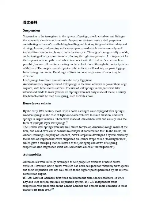
英文资料SuspensionSuspension is the term given to the system of springs, shock absorbers and linkages that connects a vehicle to its wheels. Suspension systems serve a dual purpose –contributing to the car's roadholding/handling and braking for good active safety and driving pleasure, and keeping vehicle occupants comfortable and reasonably well isolated from road noise, bumps, and vibrations,etc. These goals are generally at odds, so the tuning of suspensions involves finding the right compromise. It is important for the suspension to keep the road wheel in contact with the road surface as much as possible, because all the forces acting on the vehicle do so through the contact patches of the tires. The suspension also protects the vehicle itself and any cargo or luggage from damage and wear. The design of front and rear suspension of a car may be different.Leaf springs have been around since the early Egyptians.Ancient military engineers used leaf springs in the form of bows to power their siege engines, with little success at first. The use of leaf springs in catapults was later refined and made to work years later. Springs were not only made of metal, a sturdy tree branch could be used as a spring, such as with a bow.Horse drawn vehiclesBy the early 19th century most British horse carriages were equipped with springs; wooden springs in the case of light one-horse vehicles to avoid taxation, and steel springs in larger vehicles. These were made of low-carbon steel and usually took the form of multiple layer leaf springs.[1]The British steel springs were not well suited for use on America's rough roads of the time, and could even cause coaches to collapse if cornered too fast. In the 1820s, the Abbot Downing Company of Concord, New Hampshire developed a system whereby the bodies of stagecoaches were supported on leather straps called "thoroughbraces", which gave a swinging motion instead of the jolting up and down of a spring suspension (the stagecoach itself was sometimes called a "thoroughbrace")AutomobilesAutomobiles were initially developed as self-propelled versions of horse drawn vehicles. However, horse drawn vehicles had been designed for relatively slow speeds and their suspension was not well suited to the higher speeds permitted by the internal combustion engine.In 1903 Mors of Germany first fitted an automobile with shock absorbers. In 1920 Leyland used torsion bars in a suspension system. In 1922 independent front suspension was pioneered on the Lancia Lambda and became more common in mass market cars from 1932.[2]Important propertiesSpring rateThe spring rate (or suspension rate) is a component in setting the vehicle's ride height or its location in the suspension stroke. Vehicles which carry heavy loads will often have heavier springs to compensate for the additional weight that would otherwise collapse a vehicle to the bottom of its travel (stroke). Heavier springs are also used in performance applications where the loading conditions experienced are more extreme. Springs that are too hard or too soft cause the suspension to become ineffective because they fail to properly isolate the vehicle from the road. Vehicles that commonly experience suspension loads heavier than normal have heavy or hard springs with a spring rate close to the upper limit for that vehicle's weight. This allows the vehicle to perform properly under a heavy load when control is limited by the inertia of the load. Riding in an empty truck used for carrying loads can be uncomfortable for passengers because of its high spring rate relative to the weight of the vehicle. A race car would also be described as having heavy springs and would also be uncomfortably bumpy. However, even though we say they both have heavy springs, the actual spring rates for a 2000 lb race car and a 10,000 lb truck are very different. A luxury car, taxi, or passenger bus would be described as having soft springs. Vehicles with worn out or damaged springs ride lower to the ground which reduces the overall amount of compression available to the suspension and increases the amount of body lean. Performance vehicles can sometimes have spring rate requirements other than vehicle weight and load.Mathematics of the spring rateSpring rate is a ratio used to measure how resistant a spring is to being compressed or expanded during the spring's deflection. The magnitude of the spring force increases as deflection increases according to Hooke's Law. Briefly, this can be stated aswhereF is the force the spring exertsk is the spring rate of the spring.x is the displacement from equilibrium length i.e. the length at which the spring is neither compressed or stretched.Spring rate is confined to a narrow interval by the weight of the vehicle,load the vehicle will carry, and to a lesser extent by suspension geometry and performance desires.Spring rates typically have units of N/mm (or lbf/in). An example of a linear spring rate is 500 lbf/in. For every inch the spring is compressed, it exerts 500 lbf. Anon-linear spring rate is one for which the relation between the spring's compression and the force exerted cannot be fitted adequately to a linear model. For example, the first inch exerts 500 lbf force, the second inch exerts an additional 550 lbf (for a total of 1050 lbf), the third inch exerts another 600 lbf (for a total of 1650 lbf). In contrast a 500 lbf/in linear spring compressed to 3 inches will only exert 1500 lbf.The spring rate of a coil spring may be calculated by a simple algebraic equation or it may be measured in a spring testing machine. The spring constant k can be calculated as follows:where d is the wire diameter, G is the spring's shear modulus (e.g., about 12,000,000 lbf/in² or 80 GPa for steel), and N is the number of wraps and D is the diameter of the coil.Wheel rateWheel rate is the effective spring rate when measured at the wheel. This is as opposed to simply measuring the spring rate alone.Wheel rate is usually equal to or considerably less than the spring rate. Commonly, springs are mounted on control arms, swing arms or some other pivoting suspension member. Consider the example above where the spring rate was calculated to be500 lbs/inch, if you were to move the wheel 1 inch (without moving the car), the spring more than likely compresses a smaller amount. Lets assume the spring moved 0.75 inches, the lever arm ratio would be 0.75 to 1. The wheel rate is calculated by taking the square of the ratio (0.5625) times the spring rate. Squaring the ratio is because the ratio has two effects on the wheel rate. The ratio applies to both the force and distance traveled.Wheel rate on independent suspension is fairly straight-forward. However, special consideration must be taken with some non-independent suspension designs. Take the case of the straight axle. When viewed from the front or rear, the wheel rate can be measured by the means above. Yet because the wheels are not independent, when viewed from the side under acceleration or braking the pivot point is at infinity (because both wheels have moved) and the spring is directly inline with the wheel contact patch. The result is often that the effective wheel rate under cornering is different from what it is under acceleration and braking. This variation in wheel rate may be minimized by locating the spring as close to the wheel as possible.Roll couple percentageRoll couple percentage is the effective wheel rates, in roll, of each axle of the vehicle just as a ratio of the vehicle's total roll rate. Roll Couple Percentage is critical in accurately balancing the handling of a vehicle. It is commonly adjusted through the use of anti-roll bars, but can also be changed through the use of different springs.A vehicle with a roll couple percentage of 70% will transfer 70% of its sprung weight transfer at the front of the vehicle during cornering. This is also commonly known as "Total Lateral Load Transfer Distribution" or "TLLTD".Weight transferWeight transfer during cornering, acceleration or braking is usually calculated per individual wheel and compared with the static weights for the same wheels.The total amount of weight transfer is only affected by 4 factors: the distance between wheel centers (wheelbase in the case of braking, or track width in the case of cornering) the height of the center of gravity, the mass of the vehicle, and the amount of acceleration experienced.The speed at which weight transfer occurs as well as through which components it transfers is complex and is determined by many factors including but not limited to roll center height, spring and damper rates, anti-roll bar stiffness and the kinematic design of the suspension links.Unsprung weight transferUnsprung weight transfer is calculated based on the weight of the vehicle's components that are not supported by the springs. This includes tires, wheels, brakes, spindles, half the control arm's weight and other components. These components are then (for calculation purposes) assumed to be connected to a vehicle with zero sprung weight. They are then put through the same dynamic loads. The weight transfer for cornering in the front would be equal to the total unsprung front weight times theG-Force times the front unsprung center of gravity height divided by the front track width. The same is true for the rear.Suspension typeDependent suspensions include:∙Satchell link∙Panhard rod∙Watt's linkage∙WOBLink∙Mumford linkage∙Live axle∙Twist beam∙Beam axle∙leaf springs used for location (transverse or longitudinal)The variety of independent systems is greater and includes:∙Swing axle∙Sliding pillar∙MacPherson strut/Chapman strut∙Upper and lower A-arm (double wishbone)∙multi-link suspension∙semi-trailing arm suspension∙swinging arm∙leaf springsArmoured fighting vehicle suspensionMilitary AFVs, including tanks, have specialized suspension requirements. They can weigh more than seventy tons and are required to move at high speed over very rough ground. Their suspension components must be protected from land mines and antitank weapons. Tracked AFVs can have as many as nine road wheels on each side. Many wheeled AFVs have six or eight wheels, to help them ride over rough and soft ground. The earliest tanks of the Great War had fixed suspensions—with no movement whatsoever. This unsatisfactory situation was improved with leaf spring suspensions adopted from agricultural machinery, but even these had very limited travel. Speeds increased due to more powerful engines, and the quality of ride had to be improved. In the 1930s, the Christie suspension was developed, which allowed the use of coil springs inside a vehicle's armoured hull, by redirecting the direction of travel using a bell crank. Horstmann suspension was a variation which used a combination of bell crank and exterior coil springs, in use from the 1930s to the 1990s.By the Second World War the other common type was torsion-bar suspension, getting spring force from twisting bars inside the hull—this had less travel than the Christie type, but was significantly more compact, allowing the installation of larger turret rings and heavier main armament. The torsion-bar suspension, sometimes including shock absorbers, has been the dominant heavy armored vehicle suspension since the Second World War.中文翻译悬吊系统(亦称悬挂系统或悬载系统)是描述一种由弹簧、减震筒和连杆所构成的车用系统,用于连接车辆与其车轮。

附录附录1Automobile anti-lock braking system (ABS) Abstract: This article introduced briefly the automobile anti-lock braking system (Anti-lock Braking System, is called ABS) the control principle, the control technology which used in the present automobile anti-lock braking system has carried on the summary, and has carried on the forecast to its trend of development.Key word: Automobile anti-lock braking system control technology1.outlineAlong with automobile industry's rapid development and highway's unceasing construction, automobile's travel security more and more takes seriously for the people. To satisfy in comprehensively the brake process the automobile to the brake request, causes the brake braking force assignment to hasten reasonably. The automobile anti-lock braking system (i.e. ABS) more and more has applied on the automobile.“ABS” Chinese translates is “against deadlocks the brake system”. It is one kind has the skid prevention, against to deadlock and so on merit auto safety control systems. ABS is in the convention brake system foundation advanced version technology, separable mechanical and electronic formula two kinds.On the modern automobile installs the anti-lock braking system massively, ABS both has the ordinary braking system's brake function, and could prevent the wheel to deadlock, enables the automobile still to change under the stopping, guaranteed that automobile's brake yawing stability, prevented to have the side-slipping and to run, was on the present automobile is most advanced, the brake effect best arresting gear.The ordinary braking system applies the brake in the slippery road surface, or in emergency brake, because the wheel is easy the braking force to surpass the tire and the ground friction force hugs safely dies.The automobile anti-lock braking system is refers to the automobile in the brake process to be able the real-time determination wheel's glide rate, the automatic control function on wheel's braking moment, prevents the wheel to hug dies. Thusobtains the best brake potency the electronic installation. It can wheel's glide rate control in certain scope, use fully between the tire and the road surface adhesion, reduces the stopping distance effectively, obviously enhances when the car braking controllability and stability, when each kind of traffic accident which has avoided the wheel hugs dies easy to appear. along with brake intensity's increase, the wheel rolling ingredient are getting fewer and fewer, but skids the ingredient to be getting more and more, generally explains in the brake process with glide rate S to skid ingredient how many. The glide rate is bigger, the glide ingredient are less.And: u-- wheel center speed; r-- does not have time the ground braking force wheel rolling radius; w-- wheel's angular speed.Longitudinal and the lateral adhesion coefficient may express for the wheel slip rate function (e.g. Figure 1). The most greatly longitudinal coefficient of adhesion corresponds the glide rate is called critical point of fixity SK. Grips fast the pace according to the control theory is smaller than the SK region is called the stable brake area, what SK later has custom-made unstable moves the area. ABS is precisely uses between the path and tire's relations, compulsory wheel slip rate control nearby critical point of fixity SK, enables the road surface adhesion property to obtain the fullest display, thus achieves the best brake effect.Figure 1 coefficient of adhesion - glide rate curveAt present uses ABS mainly by a round fast sensor, the electronic control unit, appendices and so on pressure control valve and group of lines, pipeline is composed. The ABS development is mainly studies the design optimization operation and the control procedure software, realizes the real-time precise brake adjustment technology, simultaneously raises hardware's level.2.Control technology used by ABS nowThe ABS control effect is decided control technology [4] which to a great extentuses in the system. At present uses is mainly the logical threshold value control technology. To further enhance ABS the performance, but also proposed some based on the glide rate control technology, like the PID control, the glide modality change the structure controls, fuzzy control and so on. Each kind of control approaches the expectation by the different control rule the spot.2.1PID controlsThe definition expects glide rate S0 and difference of the actual glide rate S for ning error e=S-S0, then the PID control rule may be represented as:Therefore, the ABS controller's design sums up finally as, according to the ABS dynamic system, determined group of best parameter Kp, Ki and Kd, enable wheel's glide rate to approach hypothesis goal S0 by the quickest way.2.2The glide modality changes the structure controlAgainst holds the dead brake by the automobile the basic principle to be possible to know, its brake process's essential question is wheel's glide rate control in coefficient of adhesion peak point Sk, then the glide modality changed structure basis system condition, the deviation and the derivative value then, in the different controlled area, by perfect switch's way hand-off control quantity's size and the mark, the guarantee system in the glide region very small scope, the state point locus (S,×S) along moved the festival curve to slide slippery to the control objective (Sk,0). usually takes the braking moment for controlled variable U, the cut condition is:And Mb-, Mb+ represent the braking moment which decided by the governing system to reduce, to increase two different conditions separately.For the cut function, e=S-Sk is the actual glide rate relative target point deviation.2.3Fuzzy controlRegarding take the glide rate as controlled member's anti-lock braking system, its input value takes the expectation glide rate and wheel actual glide rate deviation E as well as deviation's rate of change EC, the output for the brake line flowing tubing head pressure. Uses the belt modification factor the fuzzy controller, uses the control list summary which the fuzzy reasoning algorithm forms is an analysis formula:U =α × E + (1-α)ECAnd Alpha is the modification factor, Alpha the value size has reflected directly to the deviation and the deviation rate of change weighting degree. Through the adjustment modification factor Alpha, may change the control rule. When Alpha is big, indicated that is big to deviation's weighting, the step response is quick, the control energy mainly uses in reducing the deviation, but easy to present the over modulation; When Alpha is small, the control goal reduces the over modulation, but the response process is slow. Usually uses the belt two Alpha values the modification factor expressions to be able to request on the satisfiability, namely:And, modification factor α1, α2∈(0,1), and α12.4Logical threshold value controlThis method establishes some control limit in advance to certain controlled variable (threshold) the value, when applies the brake, according to the computation real-time parameter value and the corresponding threshold value's size relations, determines wheel's state of motion, thus the control adjustment brake pressure, gains enough big brake intensity and the good yawing stability. Often includes as the ABS controlled variable: Wheel skidding rate S, the wheel rotates the angle adds (reduces) the speed Omega and the rate of change .ω and so on three kind of description wheel movement situation or dynamics condition parameter. Because only uses a controlled variable difficulty with to guarantee that ABS has the good performance under each kind of travel condition, therefore, the logical threshold value control method usually rotates at present the wheel the angle adds (reduces) the speed to take the primary control parameter, but takes wheel's glide rate S the secondary control parameter. And the glide rate is from each wheel fast signal after certain logic determined automobile's reference velocity, calculates the reference glide rate, has the difference with the actual glide rate.2.5Double parameter contro lDouble parameter control's ABS, by the vehicle speed sensor (velocity radar), a round fast sensor, the control device (computer) and the implementing agency is composed.Its principle of work is the vehicle speed sensor and a round fast sensor, separately signal input the vehicle speed and round fast the computer, calculates the actual slipping rate based on the computer, and 15% one 20% does with the idealslipping rate compares, fluctuates brake's braking force again through the solenoid valve. this kind tows the fast sensor commonly used Doppler velocity radar. When the automobile goes, the Doppler radar antenna by certain frequency to the earth launching electromagnetic wave, simultaneously receives the electromagnetic wave which unceasingly reflects, surveys the automobile radar launch and the receive differential value, then may calculate the automobile vehicle speed accurately. But turns the fast sensor to install in the transmission gearbox outer covering, actuates by the transmission gearbox output shaft, it is a pulse electrical machinery, produces frequency and round intensive direct proportion. The implementing agency and so on is composed of the solenoid valve and the relay. Solenoid valve adjustment braking force, with the aim of maintaining the ideal slipping rate. This kind of ABS may guarantee that the slipping rate ideal control, against holds the braking quality to be good, but because increased a velocity radar, therefore the structure is complex, the cost is also high.2.6Single parameter controlIt take controls wheel's angle retarded velocity as the object, controls wheel's braking force, realizes against holds the dead brake, its structure mainly by a round fast sensor, the controller (computer) and the solenoid valve is composed. For accurate meter wheel fast, the sensing and between the wheel tooth ring should leave leeway the 1mm gap. In order to avoid the water, the putty, the dust to the sensor the influence, before the installment, should the sensor replenishment butter. The solenoid valve uses in wheel brake's pressure control. Regarding four channel braking system, a vehicle rim has a solenoid valve; Three channel braking system, each front wheel has one, two trailing wheels use in common one. The solenoid valve has three hydraulic pressure holes, separately applies the brake with the brake master cylinder and the wheel to divide the cylinder to be connected, and can realize pressure lifting, pressure maintenance, the pressure drop accent to press the function. The principle of work is as follows:1) Pressure-rise when the solenoid valve does not work, the brake master cylinder connection and applies the brake to divide the cylinder connection respectively to go nonstop. Because the main spring intensity is big, makes charging valve opening, the brake pressure to increase.2) pressure maintenance, when wheel's brake divides in cylinder's pressure grows to certain value, charging valve cut-off closure. The support maintains at the compound state, three panels seal, maintain the brake pressures mutually.3) voltage dropping, when the solenoid valve works, the support overcomes two spring's tension, opens the discharge meat to cause to apply the brake to divide cylinder pressure drop. Once the pressure reduces, the solenoid valve transforms to the pressure maintenance condition, or pressure-rise ready condition.The control device ECU primary mission is the signal which passes on various wheels' sensor carries on the computation, the analysis, the enlargement and the distinction, outputs again from the output stage the command signal the solenoid valve, carries out the brake pressure adjustment task. The electronic control, by four major part is composed, input level A, controller B, output stage C, constant voltage and protective device D. Electronic controller by 4 101tz frequency actuation solenoid valves, this is the pilot is unable to achieve. This kind of single parameter control mode ABS, because the structure is simple, the cost is low, therefore the present use is broad.Mostly has provided this kind of single parameter control mode ABS in the American Chrysler custom car. It is loaded with a round fast sensor on passenger vehicle's four wheels. The installment has 45 teeth or 100 tooth's tooth rings on the axle tree, turns a fast sensor's sensing attire to go against in the tooth ring. When the wheel rotates, causes the sensor to produce the voltage signal unceasingly, and inputs the computer, the ideal speed compares with RoM, figures out wheel's speed-up or the deceleration, issues pressure-rise or the release of pressure instruction to the solenoid valve, controls applies the brake to divide the cylinder braking force.3.The problems by used the ABS system(1) replaces the brake or the replacement hydraulic pressure braking system part, should arrange only in brake line's air, in order to avoid influence braking system's normal work.(2) is loaded with the ABS automobile, every year should replace a brake fluid. Otherwise, the brake fluid water absorbability is very strong, after the watery, not only will reduce the boiling point, will have the corrosion, will also create the brake potency decline.(3) inspects the ABS anti-lock braking system, to cramp out the power source first.4.Trend of developmentUses the logical threshold value control algorithm, may avoid a series of numerous and diverse theoretical analysis and to some element of certainty quotameasurement. Simplified controller's design, because moreover only need determine wheel's angular speed, is advantageous realizes, therefore the load cost is low. This algorithm already drew close maturely, for current automobile ABS system universal use, but it by no means best control algorithm. Because under the different state of roads each kind of threshold value and guarantees presses the time is the empirical value which obtains after the repeated test, does not have the very explicit theory basis, therefore the ABS development's cycle is long, and the control quality guaranteed with difficulty.Easy to realize the stepless control based on the glide rate control algorithm, and has the very explicit theory to instruct, but present restricts the cost question which its development the bottleneck is mainly realizes, believed according to ours research, from now on ABS control algorithm development direction in the following several aspects.(1)aims at current widely uses the logical threshold value control algorithm which exists, the research can track the road surface characteristic change, causes the ABS each performance index to be at the optimum condition throughout the control algorithm. And the predictive control technology is worth taking seriously. Because when the brake process, friction characteristic between the tire and the road surface causes the anti-lock braking system has the very obvious misalignment, the denaturation and the uncertainty. Therefore difficulty with establishes its precise mathematical model, but the predictive control has the basic characteristic which the forecast model, the trundle optimize and feed back adjust, may act according to some optimized target design control system, determined that a control quantity the time series, after causing in period of time to move the quantity and the process will soften between the expectation path's error to be smallest in the future. What because this algorithm uses is the online trundle optimizes unceasingly, and unceasingly carries on the feedback in the optimal process through the actual system output and the forecast model output's error to adjust, can therefore overcome to a certain extent as a result of the forecast model error and certain uncertainty disturbance and so on influence, enables system's robustness to obtain the enhancement.(2)Is smaller along with the volume, the price is cheaper, the reliable higher vehicle speed sensor's appearance, in the ABS system will increase the vehicle speed sensor to become possible, the definite wheel slip rate will become is accurate and isfast. And the non-contact type's vehicle speed sensor (for example electro-optical type, Doppler and so on) the present will most have the possibility to apply in the automobile ABS system. This time may take seriously based on the glide rate control algorithm. And the fuzzy control will not rely on the object by it the mathematical model, is advantageous uses person's experience knowledge, robustness is good, simple practical and so on characteristics, but widely will be used.(3)Changes the multi-objectives by the sole ABS control objective integrated control [10], appeared not only the force of traction control system (TCS) can prevent the wheel in the brake process to occur hugs dies, moreover can in the actuation process (be specially in processes and so on start, acceleration, curve) prevents the driving gear to have the slipping, causes automobile's in actuation process yawing stability, to change the operation ability and the pick-up and so on also has the enhancement. In the future automobile electronic control system toward from multi-electronic control unit (ECU) the scattered independent control to the sole ECU complete bikes control, realizes data sharing and the integrated control direction by the network way develops; Or develops to the dynamic hierarchical control direction, namely each dispersion control system's ECU is not only the respective independence constructs own dynamic compensator, moreover must establish a high-level dynamic synchronizer to help unified again to determine each ECU the control policy, strengthens each ECU the control, when the solution dispersion control system existence unstable mold cannot use dynamic dispersion control calm question [11], enables the complete bikes overall performance to obtain the guarantee.5.SummaryThe automobile anti-lock braking system (ABS) can enhance the automobile, in the low coefficient of adhesion or changes under the coefficient of adhesion road surface condition the braking quality. At present the ABS control technology mainly uses the logical threshold value control method, but along with vehicle speed sensor technology development, based on wheel slip rate each kind of control algorithm by widespread value and use. Moreover. In the future the automobile electronic control technology and the equipment will realize the resource sharing and the integrated control by the network way, and toward the multi-objective integrated controls, enhances the system performance cost ratio the direction to develop.汽车防抱死制动系统(ABS)摘要:本文简要介绍了汽车防抱死制动系统(Anti-lock Braking System,简称ABS)的控制原理,对目前汽车防抱死制动系统所采用的控制技术进行了综述,并对其发展趋势进行了预测。

附录附录A外文资料翻译Study on the testing system of the auto AC chassisDynamometerWith the incessant progress of the science and technology, the automobileindustry of developes rapidly. The structure of automobile becomes perfect and the performance gets enhanced. On the one hand, the higher demand of automobile performance accelerates the coalescent between traditional automobile technique and modern electron technology,and the automobile technical indexes have been enhanced greatly.On the other hand it accelerates the development of integrated automobile detection technique, and speeds up the research and renovation of the automobile testing equipments.There are two methods for automobile performance test. One is the outdoor road test, the other one is the indoor frame test. The weather,condition of the road and the driving skills have great influence on the road test. However these factors have little influence on the results of indoor frame test. So the indoor frame test gets popular in the automobile test. Automobile chassis dynamometer plays an important role in the automobile detection and diagnosis. Dynamic performancetest can been done on the auto chassis dynamometer test bed. With the help of fuel consumption instrument and automotive flue exhaust analyzer, fuel economy test and the analysis of exhaust gas can been done easily. The domestic auto chassis dynamometers get behind that of the developed country. The domestic chassis dynamometers are mainly eddy current dynamometer and hydraulic dynamometer. Generally these dynamometers are equipped with flywheels to simulate the accelerate resistance.By control of the electromagnetic clutch,assemble the required flywheels according to the weight of the car.But the limited flywheels can’t realize the continuous simulation of the inertia.They can’t satisfy the testing demand of the various cars nowadays.And the test precision needs being improved.Thus this thesis puts forward a new method with the help of an AC electric dynamometer.The principle of AC electric dynamometer is similar as the asynchronous electromotor.With the rapid development of frequency converter,the AC electric dynamometer becomes more popular and easy to be controlled.The paper includes these main points as follows.1. Simply introduce the principle and structure of the automobile chassis dynamometer.Adopts the anti-swing devicefor the driving wheel, and solves the swing of front-wheel drive cars. In order to recur the road resistance of the automobile,analyse the resistances of the car driving on the road and on the chassis dynamometer,draw a resistance equation separately about the car.Then make contrast of the two equations,find their difference and put forward the electric simulation model.It provides the theoretic basis for the next electric simulation on the AC electric dynamometer.=road F 2Cu Bu A +++ mg·sin α+dtdu m ∙δ The model displays as follows.2. Give the general technical demands.Analyse the principle of AC electric dynamometer.It has three running conditions according the difference of the slip.They are regeneration condition,electric drive condition and electromagnetic brake condition.For this reason the AC electric dynamometer is proper to be used in chassis dynamometer and can satisfy the e the advanced AC variable frequency technique to control the dynamometer.This system adopts the direct torque control of frequency converter.By the control of frequency converter the system can realize the auto speed regulate,auto torque regulate and auto load regulate.3. After choosing the proper sensors for the system, designthe part of data collection and analysis,and analyse the amplification of analog signals in detail.In order to do the electric simulation the speed and acceleration are necessary.The system uses an improved method to measure the speed, and uses least square method to get the acceleration.It has excellent precision at low speed and high speed.Analyse the interferential factors,and adopt proper measures to restrain the disturb and assure the veracity of the results.4. The testing system is based on Windows XP and program with VC++6.0. The testing system can operate alone and can operate online. The software of the system adopts blocking design according to the system design demand.That is to say,if any one logic part of the software was changed,it wouldn’t affect other parts.And any module can be transferred by other modules.The testing interface is friendly.Take the acceleration test and sliding performance test for example, introduce their testing process. At last give the flow of the whole program.5. Analyse the reason of the error, demarcate the speed sensor and force sensor to see the quality of the linearity of the sensors.The results show the two sensors have good linearity and satisfy GB/T18276-2000 ‘Test method and evaluation index for the automobile dynamic frame benches’.Use a truck do theacceleration test from 30km/h to 90km/h on the road and on the chassis dynamometer separately,then make contrast of the results and show that the electric simulation model is correct basically.The automobile chassis dynamometer itself is very complicated.The thesis can’t describe every aspe ct in detail.And it is hard to avoid some mistakes and disadvantages.The testing system needs to been further researched and improved,and needs doing more experiments to validate its feasibility汽车交流底盘测功机测试系统研究随着科学技术的不断进步,汽车工业得到了迅猛的发展。
附录Automobile Brake SystemJohn FentonThe braking system is the most important system in cars. If the brakes fail, the result can be disastrous. Brakes are actually energy conversion devices, which convert the kinetic energy (momentum) of the vehicle into thermal energy (heat).When stepping on the brakes, the driver commands a stopping force ten times as powerful as the force that puts the car in motion. The braking system can exert thousands of pounds of pressure on each of the four brakes.Two complete independent braking systems are used on the car. They are the service brake and the parking brake.The service brake acts to slow, stop, or hold the vehicle during normal driving. They are foot-operated by the driver depressing and releasing the brake pedal. Theprimary purpose of the brake is to hold the vehicle stationary while it is unattended. The parking brake is mechanically operated by when a separate parking brake foot pedal or hand lever is set.The brake system is composed of the following basic components: the “master cylinder” which is located under the hood, and is directly connected to the brake pedal, converts driver foot’s mechanical pressure into hydraulicpressure. S teel “brake lines” and flexible “brake hoses” connect the master cylinder to the “slave cylinders” located at each wheel. Brake fluid, specially designed to work in extreme conditions, fills the system. “Shoes” and “pads” are pushed by the slave cylinders to contact the “drums” and “rotors” thus causing drag, which (hopefully) slows the car.The typical brake system consists of disk brakes in front and either disk or drum brakes in the rear connected by a system of tubes and hoses that link the brake at each wheel to the master cylinder .Basically, all car brakes are friction brakes. When the driver applies the brake, the control device forces brake shoes, or pads, against the rotating brake drum or disks at wheel. Friction between the shoes or pads and the drums or disks then slows or stops the wheel so that the car is braked.In most modern brake systems (see Figure 15.1), there is a fluid-filled cylinder, called master cylinder, which contains two separate sections, there is a piston in each section and both pistons are connected to a brake pedal in the driver’s compartment. When the brake is pushed down, brake fluid is sent from the master cylinder to the wheels. At the wheels, the fluid pushes shoes, or pads, against revolving drums or disks. The friction between the stationary shoes, or pads, and the revolving drums or disks slows and stops them. This slows or stops the revolving wheels, which, in turn, slow or stop the car.The brake fluid reservoir is on top of the master cylinder. Most cars today have a transparent r reservoir so that you can see the level without openingthe cover. The brake fluid level will drop slightly as the brake pads wear. This is a normal condition and no cause for concern. If the level drops noticeably over a short period of time or goes down to about two thirds full, have your brakes checked as soon as possible. Keep the reservoir covered except for the amount of time you need to fill it and never leave a cam of brake fluid uncovered. Brake fluid must maintain a very high boiling point. Exposure to air will cause the fluid to absorb moisture which will lower that boiling point.The brake fluid travels from the master cylinder to the wheels through a series of steel tubes and reinforced rubber hoses. Rubber hoses are only used in places that require flexibility, such as at the front wheels, which move up and down as well as steer. The rest of the system uses non-corrosive seamless steel tubing with special fittings at all attachment points. If a steel line requires a repair, the best procedure is to replace the compete line. If this is not practical, a line can be repaired using special splice fittings that are made for brake system repair. You must never use copper tubing to repair a brake system. They are dangerous and illegal.Drum brakes, it consists of the brake drum, an expander, pull back springs, a stationary back plate, two shoes with friction linings, and anchor pins. The stationary back plate is secured to the flange of the axle housing or to the steering knuckle. The brake drum is mounted on the wheel hub. There is a clearance between the inner surface of the drum and the shoe lining. To apply brakes, the driver pushes pedal, the expander expands the shoes and pressesthem to the drum. Friction between the brake drum and the friction linings brakes the wheels and the vehicle stops. To release brakes, the driver release the pedal, the pull back spring retracts the shoes thus permitting free rotation of the wheels.Disk brakes, it has a metal disk instead of a drum. A flat shoe, or disk-brake pad, is located on each side of the disk. The shoes squeeze the rotating disk to stop the car. Fluid from the master cylinder forces the pistons to move in, toward the disk. This action pushes the friction pads tightly against the disk. The friction between the shoes and disk slows and stops it. This provides the braking action. Pistons are made of either plastic or metal. There are three general types of disk brakes. They are the floating-caliper type, the fixed-caliper type, and the sliding-caliper type. Floating-caliper and sliding-caliper disk brakes use a single piston. Fixed-caliper disk brakes have either two or four pistons.The brake system assemblies are actuated by mechanical, hydraulic or pneumatic devices. The mechanical leverage is used in the parking brakes fitted in all automobile. When the brake pedal is depressed, the rod pushes the piston of brake master cylinder which presses the fluid. The fluid flows through the pipelines to the power brake unit and then to the wheel cylinder. The fluid pressure expands the cylinder pistons thus pressing the shoes to the drum or disk. If the pedal is released, the piston returns to the initial position, the pull back springs retract the shoes, the fluid is forced back to the mastercylinder and braking ceases.The primary purpose of the parking brake is to hold the vehicle stationary while it is unattended. The parking brake is mechanically operated by the driver when a separate parking braking hand lever is set. The hand brake is normally used when the car has already stopped. A lever is pulled and the rear brakes are approached and locked in the “on” position. The car may now be left without fear of its rolling away. When the driver wants to move the car again, he must press a button before the lever can be released. The hand brake must also be able to stop the car in the event of the foot brake failing. For this reason, it is separate from the foot brake uses cable or rods instead of the hydraulic system.Anti-lock Brake SystemAnti-lock brake systems make braking safer and more convenient, Anti-lock brake systems modulate brake system hydraulic pressure to prevent the brakes from locking and the tires from skidding on slippery pavement or during a panic stop.Anti-lock brake systems have been used on aircraft for years, and some domestic car were offered with an early form of anti-lock braking in late 1990’s. Recently, several automakers have introduced more sophisticated anti-lock system. Investigations in Europe, where anti-lock braking systems have been available for a decade, have led one manufacture to state that the number of traffic accidents could be reduced by seven and a half percent if allcars had anti-lock brakes. So some sources predict that all cars will offer anti-lock brakes to improve the safety of the car.Anti-lock systems modulate brake application force several times per second to hold the tires at a controlled amount of slip; all systems accomplish this in basically the same way. One or more speed sensors generate alternating current signal whose frequency increases with the wheel rotational speed. An electronic control unit continuously monitors these signals and if the frequency of a signal drops too rapidly indicating that a wheel is about to lock, the control unit instructs a modulating device to reduce hydraulic pressure to the brake at the affected wheel. When sensor signals indicate the wheel is again rotating normally, the control unit allows increased hydraulic pressure to the brake. This release-apply cycle occurs several time per second to “pump” the brakes like a driver might but at a much faster rate.In addition to their basic operation, anti-lock systems have two other things in common. First, they do not operate until the brakes are applied with enough force to lock or nearly lock a wheel. At all other times, the system stands ready to function but does not interfere with normal braking. Second, if the anti-lock system fail in any way, the brakes continue to operate without anti-lock capability. A warning light on the instrument panel alerts the driver when a problem exists in the anti-lock system.The current Bosch component Anti-lock Braking System (ABSⅡ), is asecond generation design wildly used by European automakers such as BWM, Mercedes-Benz and Porsche. ABSⅡsystem consists of : four wheel speed sensor, electronic control unit and modulator assembly.A speed sensor is fitted at each wheel sends signals about wheel rotation to control unit. Each speed sensor consists of a sensor unit and a gear wheel. The front sensor mounts to the steering knuckle and its gear wheel is pressed onto the stub axle that rotates with the wheel. The rear sensor mounts the rear suspension member and its gear wheel is pressed onto the axle. The sensor itself is a winding with a magnetic core. The core creates a magnetic field around the winding, and as the teeth of the gear wheel move through this field, an alternating current is induced in the winding. The control unit monitors the rate o change in this frequency to determine impending brake lockup.The control unit’s function can be divided into three parts: signal processing, logic and safety circuitry. The signal processing section is the converter that receives the alternating current signals form the speed sensors and converts them into digital form for the logic section. The logic section then analyzes the digitized signals to calculate any brake pressure changes needed. If impending lockup is sensed, the logic section sends commands to the modulator assembly.The hydraulic modulator assembly regulates pressure to the wheel brakes when it receives commands from the control utuit. The modulator assemblycan maintain or reduce pressure over the level it receives from the master cylinder, it also can never apply the brakes by itself. The modulator assembly consists of three high-speed electric solenoid valves, two fluid reservoirs and a turn delivery pump equipped with inlet and outlet check valves. The modulator electrical connector and controlling relays are concealed under a plastic cover of the assembly.Each front wheel is served by electric solenoid valve modulated independently by the control unit. The rear brakes are served by a single solenoid valve and modulated together using the select-low principle. During anti-braking system operation, the control unit cycles the solenoid valves to either hold or release pressure the brake lines. When pressure is released from the brake lines during anti-braking operation, it is routed to a fluid reservoir. There is one reservoir for the front brake circuit. The reservoirs are low-pressure accumulators that store fluid under slight spring pressure until the return delivery pump can return the fluid through the brake lines to the master cylinder.汽车制动系统约翰·芬顿制动系统是汽车中最重要的系统。
Machine design theoryThe machine design is through designs the new product or improves the old product to meet the human need the application technical science. It involves the project technology each domain, mainly studies the product the size, the shape and the detailed structure basic idea, but also must study the product the personnel which in aspect the and so on manufacture, sale and use question.Carries on each kind of machine design work to be usually called designs the personnel or machine design engineer. The machine design is a creative work. Project engineer not only must have the creativity in the work, but also must in aspect and so on mechanical drawing, kinematics, engineerig material, materials mechanics and machine manufacture technology has the deep elementary knowledge.If front sues, the machine design goal is the production can meet the human need the product. The invention, the discovery and technical knowledge itself certainly not necessarily can bring the advantage to the humanity, only has when they are applied can produce on the product the benefit. Thus, should realize to carries on before the design in a specific product, must first determine whether the people do need this kind of productMust regard as the machine design is the machine design personnel carries on using creative ability the product design, the system analysis and a formulation product manufacture technology good opportunity. Grasps the project elementary knowledge to have to memorize some data and the formula is more important than. The merely service data and the formula is insufficient to the completely decision which makes in a good design needs. On the other hand, should be earnest precisely carries on all operations. For example, even if places wrong a decimal point position, also can cause the correct design to turn wrongly.A good design personnel should dare to propose the new idea, moreover is willing to undertake the certain risk, when the new method is not suitable, use original method. Therefore, designs the personnel to have to have to have the patience, because spendsthe time and the endeavor certainly cannot guarantee brings successfully. A brand-new design, the request screen abandons obsoletely many, knows very well the method for the people. Because many person of conservativeness, does this certainly is not an easy matter. A mechanical designer should unceasingly explore the improvement existing product the method, should earnestly choose originally, the process confirmation principle of design in this process, with has not unified it after the confirmation new idea.Newly designs itself can have the question occurrence which many flaws and has not been able to expect, only has after these flaws and the question are solved, can manifest new goods come into the market the product superiority. Therefore, a performance superior product is born at the same time, also is following a higher risk. Should emphasize, if designs itself does not request to use the brand-new method, is not unnecessary merely for the goal which transform to use the new method.In the design preliminary stage, should allow to design the personnel fully to display the creativity, not each kind of restraint. Even if has had many impractical ideas, also can in the design early time, namely in front of the plan blueprint is corrected. Only then, only then does not send to stops up the innovation the mentality. Usually, must propose several sets of design proposals, then perform the comparison. Has the possibility very much in the plan which finally designated, has used certain not in plan some ideas which accepts.How does the psychologist frequently discuss causes the machine which the people adapts them to operate. Designs personnel''s basic responsibility is diligently causes the machine to adapt the people. This certainly is not an easy work, because certainly does not have to all people to say in fact all is the most superior operating area and the operating process.Another important question, project engineer must be able to carry on the exchange and the consultation with other concerned personnel. In the initial stage, designs the personnel to have to carry on the exchange and the consultation on the preliminary design with the administrative personnel, and is approved. This generally is through the oral discussion, the schematic diagram and the writing material carries on. In order to carry on the effective exchange, needs to solve the following problem:(1) designs whether this product truly does need for the people? Whether there is competitive ability(2) does this product compare with other companies'' existing similar products?(3) produces this kind of product is whether economical?(4) product service is whether convenient?(5) product whether there is sale? Whether may gain?Only has the time to be able to produce the correct answer to above question. But, the product design, the manufacture and the sale only can in carry on to the above question preliminary affirmation answer foundation in. Project engineer also should through the detail drawing and the assembly drawing, carries on the consultation together with the branch of manufacture to the finally design proposal.Usually, can have some problem in the manufacture process. Possibly can request to some components size or the common difference makes some changes, causes the components the production to change easily. But, in the project change must have to pass through designs the personnel to authorize, guaranteed cannot damage the product the function. Sometimes, when in front of product assembly or in the packing foreign shipment experiment only then discovers in the design some kind of flaw. These instances exactly showed the design is a dynamic process. Always has a better method to complete the design work, designs the personnel to be supposed unceasingly diligently, seeks these better method.Recent year, the engineerig material choice already appeared importantly. In addition, the choice process should be to the material continuously the unceasing again appraisal process. The new material unceasingly appears, but some original materials can obtain the quantity possibly can reduce. The environmental pollution, material recycling aspect and so on use, worker''s health and security frequently can attach the new limiting condition to the choice of material. In order to reduce the weight or saves the energy, possibly can request the use different material. Comes from domestic and international competition, to product service maintenance convenience request enhancement and customer''s aspect the and so on feedback pressure, can urge the people to carry on to the material reappraises. Because the material does not select when created the product responsibility lawsuit, has already had the profoundinfluence. In addition, the material and between the material processing interdependence is already known by the people clearly. Therefore, in order to can and guarantees the quality in the reasonable cost under the premise to obtain satisfaction the result, project engineer makes engineers all to have earnestly carefully to choose, the determination and the use material.Makes any product the first step of work all is designs. Designs usually may divide into several explicit stages: (a) preliminary design; (b) functional design; (c) production design. In the preliminary design stage, the designer emphatically considered the product should have function. Usually must conceive and consider several plans, then decided this kind of thought is whether feasible; If is feasible, then should makes the further improvement to or several plans. In this stage, the question which only must consider about the choice of material is: Whether has the performance to conform to the request material to be possible to supply the choice; If no, whether has a bigger assurance all permits in the cost and the time in the limit develops one kind of new material.In the functional design and the engineering design stage, needs to make a practical feasible design. Must draw up the quite complete blueprint in this stage, chooses and determines each kind of components the material. Usually must make the prototype or the working model, and carries on the experiment to it, the appraisal product function, the reliability, the outward appearance and the service maintenance and so on. Although this kind of experiment possibly can indicate, enters in the product to the production base in front of, should replace certain materials, but, absolutely cannot this point take not earnestly chooses the material the excuse. Should unify the product the function, earnestly carefully considers the product the outward appearance, the cost and the reliability. Has the achievement very much the company when manufacture all prototypes, selects the material should the material which uses with its production in be same, and uses the similar manufacture technology as far as possible. Like this has the advantage very much to the company. The function complete prototype if cannot act according to the anticipated sales volume economically to make, or is prototypical and the official production installment has in the quality and the reliable aspect is very greatly different, then this kind of prototypedoes not have the great value. Project engineer is best can completely complete the material in this stage the analysis, the choice and the determination work, but is not remains it to the production design stage does. Because, is carries on in the production design stage material replacement by other people, these people are inferior to project engineer to the product all functions understanding. In the production design stage, is should completely determine with the material related main question the material, causes them to adapt with the existing equipment, can use the existing equipment economically to carry on the processing, moreover the material quantity can quite be easy to guarantee the supply.In the manufacture process, inevitably can appear to uses the material to make some changes the situation. The experience indicated that, may use certain cheap materials to take the substitute. However, in the majority situation, in will carry on the production later to change the material to have in to start before the production to change the price which the material will spend to have to be higher than. Completes the choice of material work in the design stage, may avoid the most such situations. Started after the production manufacture to appear has been possible to supply the use the new material is replaces the material the most common reason. Certainly, these new materials possibly reduce the cost, the improvement product performance. But, must carry on the earnest appraisal to the new material, guarantees its all performance all to answer the purpose. Must remember that, the new material performance and the reliable very few pictures materials on hand such understood for the people. The majority of products expiration and the product accident caused by negligence case is because in selects the new material to take in front of substitution material, not truly understood their long-term operational performance causes.The product responsibility lawsuit forces designs the personnel and the company when the choice material, uses the best procedure. In the material process, five most common questions are: (a) did not understand or cannot use about the material application aspect most newly the best information paper; (b) has not been able to foresee and to consider the dusk year possible reasonable use (for example to have the possibility, designs the personnel also to be supposed further to forecast and the consideration because product application method not when creates consequence.ecent years many products responsibilities lawsuit case, because wrongly uses theplaintiff which the product receives the injury to accuse produces the factory, and wins the decision); (c) uses the material data not entire perhaps some data are indefinite, works as its long-term performance data is the like this time in particular;(d) the quality control method is not suitable and not after the confirmation; (e) the personnel which completely is not competent for the post by some chooses the material.Through to the above five questions analysis, may obtain these questions is does not have the sufficient reason existence the conclusion. May for avoid these questions to these questions research analyses the appearance indicating the direction. Although uses the best choice of material method not to be able to avoid having the product responsibility lawsuit, designs the personnel and the industry carries on the choice of material according to the suitable procedure, may greatly reduce the lawsuit the quantity.May see from the above discussion, the choice material people should to the material nature, the characteristic and the processing method have comprehensive and thebasic understanding.翻译:机械设计理论机械设计,通过设计新产品或改进老产品,以满足人类需要的应用技术科学。
毕业设计论文外文资料原文及译文学院:机电工程学院专业:机械设计制造及其自动化班级:学号:姓名:Mechanical engineering1.The porfile of mechanical engineeringEngingeering is a branch of mechanical engineerig,it studies mechanical and power generation especially power and movement.2.The history of mechanical engineering18th century later periods,the steam engine invention has provided a main power fountainhead for the industrial revolution,enormously impelled each kind of mechznical biting.Thus,an important branch of a new Engineering – separated from the civil engineering tools and machines on the branch-developed together with Birmingham and the establishment of the Associantion of Mechanical Engineers in 1847 had been officially recognized.The mechanical engineering already mainly used in by trial and error method mechanic application technological development into professional engineer the scientific method of which in the research,the design and the realm of production used .From the most broad perspective,the demend continuously to enhance the efficiencey of mechanical engineers improve the quality ofwork,and asked him to accept the history of the high degree of education and training.Machine operation to stress not only economic but also infrastructure costs to an absolute minimun.3.The field of mechanical engineeringThe commodity machinery development in the develop country,in the high level material life very great degree is decided each kind of which can realize in the mechanical engineering.Mechanical engineers unceasingly will invent the machine next life to produce the commodity,unceasingly will develop the accuracy and the complexity more and more high machine tools produces the machine.The main clues of the mechanical development is:In order to enhance the excellent in quality and reasonable in price produce to increase the precision as well as to reduce the production cost.This three requirements promoted the complex control system development.The most successful machine manufacture is its machine and the control system close fusion,whether such control system is essentially mechanical or electronic.The modernized car engin production transmission line(conveyer belt)is a series of complex productions craft mechanizationvery good example.The people are in the process of development in order to enable further automation of the production machinery ,the use of a computer to store and handle large volumes of data,the data is a multifunctional machine tools necessary for the production of spare parts.One of the objectives is to fully automated production workshop,three rotation,but only one officer per day to operate.The development of production for mechanical machinery must have adequate power supply.Steam engine first provided the heat to generate power using practical methods in the old human,wind and hydropower,an increase of engin .New mechanical engineering industry is one of the challenges faced by the initial increase thermal effciency and power,which is as big steam turbine and the development of joint steam boilers basically achieved.20th century,turbine generators to provide impetus has been sustained and rapid growth,while thermal efficiency is steady growth,and large power plants per kW capital consumption is also declining.Finally,mechanical engineers have nuclear energy.This requires the application of nuclear energy particularly high reliability and security,which requires solving many new rge power plants and the nuclear power plant control systems have become highly complex electroonics,fluid,electricity,water and mechanical parts networks All in all areas related to the mechanical engineers.Small internal combustion engine,both to the type (petrol and diesel machines)or rotary-type(gas turbines and Mong Kerr machine),as well as their broad application in the field of transport should also due to mechanical enginerrs.Throughout the transport,both in the air and space,or in the terrestrial and marine,mechanial engineers created a variety of equipment and power devices to their increasing cooperation with electrical engineers,especially in the development of appropration control systems.Mechanical engineers in the development of military weapons technology and civil war ,needs a similar,though its purpose is to enhance rather than destroy their productivity.However.War needs a lot of resources to make the area of techonlogy,many have a far-reaching development in peacetime efficiency.Jet aircraft and nuclear reactors are well known examples.The Biological engineering,mechanical engineering biotechnology is a relatively new and different areas,it provides for the replacement of the machine or increase thebody functions as well as for medical equipment.Artficial limbs have been developed and have such a strong movement and touch response function of the human body.In the development of artificial organ transplant is rapid,complex cardiac machines and similar equipment to enable increasingly complex surgery,and injuries and ill patients life functions can be sustained.Some enviromental control mechanical engineers through the initial efforts to drainage or irrigation pumping to the land and to mine and ventilation to control the human environment.Modern refrigeration and air-conditioning plant commonaly used reverse heat engine,where the heat from the engine from cold places to more external heat.Many mechanical engineering products,as well as other leading technology development city have side effects on the environment,producing noise,water and air pollution caused,destroyed land and landscape.Improve productivity and diver too fast in the commodity,that the renewable naturalforces keep pace.For mechanical engineers and others,environmental control is rapidly developing area,which includes a possible development and production of small quantities of pollutants machine sequnce,and the development of new equipment and teachnology has been to reduce and eliminate pollution.4.The role of mechanical engineeringThere are four generic mechanical engineers in common to the above all domains function.The 1st function is the understanding and the research mechanical science foundation.It includes the power and movement of the relationship dynamics For example,in the vibration and movement of the relationship;Automatic control;Study of the various forms of heart,energy,power relations between the thermodynamic;Fluidflows; Heat transfer; Lubricant;And material properties.The 2nd function will be conducts the research,the desing and the development,this function in turn attempts to carry on the essential change to satisfy current and the future needs.This not only calls for a clear understanding of mechanical science,and have to breakdown into basic elements of a complex system capacity.But also the need for synthetic and innovative inventions.The 3rd function is produces the product and the power,include plan,operation and maintenance.Its goal lies in the maintenance eitherenhances the enterprise or the organization longer-tern and survivabilaty prestige at the same time,produces the greatest value by the least investments and the consumption.The 4th function is mechanical engineer’s coordinated function,including the management,the consultation,as well as carries on the market marking in certain situation.In all these function,one kind unceasingly to use the science for a long time the method,but is not traditional or the intuition method tendency,this is a mechanical engineering skill aspect which unceasingly grows.These new rationalization means typical names include:The operations research,the engineering economics,the logical law problem analysis(is called PABLA) However,creativity is not rationalization.As in other areas,in mechanical engineering,to take unexpected and important way to bring about a new capacity,still has a personal,marked characteristice.5.The design of mechanical engineeringThe design of mechanical is the design has the mechanical property the thing or the system,such as:the instrument and the measuring appliance in very many situations,the machine design must use the knowledge of discipline the and so on mathematics,materials science and mechanics.Mechanical engineering desgin includeing all mechanical desgin,but it was a study,because it also includes all the branches of mechsnical engineering,such as thermodynamics all hydrodynamics in the basic disciplines needed,in the mechanical engineering design of the initial stude or mechanical design.Design stages.The entire desgin process from start to finish,in the process,a demand that is designed for it and decided to do the start.After a lot of repetition,the final meet this demand by the end of the design procees and the plan.Design considerations.Sometimes in a system is to decide which parts needs intensity parts of geometric shapesand size an important factor in this context that we must consider that the intensity is an important factor in the design.When we use expression design considerations,we design parts that may affect the entire system design features.In the circumstances specified in the design,usually for a series of such functions must be taken into account.Howeever,to correct purposes,we should recognize that,in many cases thedesign of important design considerations are not calculated or test can determine the components or systems.Especially students,wheen in need to make important decisions in the design and conduct of any operation that can not be the case,they are often confused.These are not special,they occur every day,imagine,for example,a medical laboratory in the mechanical design,from marketing perspective,people have high expectations from the strength and relevance of impression.Thick,and heavy parts installed together:to produce a solid impression machines.And sometimes machinery and spare parts from the design style is the point and not the other point of view.Our purpose is to make those you do not be misled to believe that every design decision will needreasonable mathematical methods.Manufacturing refers to the raw meterials into finished products in the enterprise.Create three distinct phases.They are:input,processing exprot.The first phase includes the production of all products in line with market needs essential.First there must be the demand for the product,the necessary materials,while also needs such as energy,time,human knowledge and technology resourcess .Finall,the need for funds to obtain all the other resources. Lose one stage after the second phase of the resources of the processes to be distributed.Processing of raw materials into finished products of these processes.To complete the design,based on the design,and then develop plans.Plan implemented through various production processes.Management of resources and processes to ensure efficiency and productivity.For example,we must carefully manage resources to ensure proper use of funds.Finally,people are talking about the product market was cast.Stage is the final stage of exporting finished or stage.Once finished just purchased,it must be delivered to the users.According to product performance,installation and may have to conduct further debugging in addition,some products,especially those very complex products User training is necessary.6.The processes of materials and maunfacturingHere said engineering materials into two main categories:metals and non-ferrous,high-performance alloys and power metals.Non-metallic futher divided into plastice,synthetic rubber,composite materials and ceramics.It said the productionproccess is divided into several major process,includingshape,forging,casting/ founding,heat treatment,fixed/connections ,measurement/ quality control and materal cutting.These processes can be further divide into each other’s craft.Various stages of the development of the manufacturing industry Over the years,the manufacturing process has four distinct stages of development, despite the overlap.These stages are:The first phase is artisanal,the second Phase is mechanization.The third phase is automation the forth Phase is integrated.When mankind initial processing of raw materials into finished products will be,they use manual processes.Each with their hands and what are the tools manuslly produced.This is totally integrated production take shape.A person needs indentification,collection materials,the design of a product to meet that demand,the production of such products and use it.From beginning to end,everything is focused on doing the work of the human ter in the industrial revolution introduced mechanized production process,people began to use machines to complete the work accomplished previously manual. This led to the specialization.Specialization in turn reduce the manufacture of integrated factors.In this stage of development,manufacturing workers can see their production as a whole represent a specific piece of the part of the production process.One can not say that their work is how to cope with the entire production process,or how they were loaded onto a production of parts finished.Development of manufacting processes is the next phase of the selection process automation.This is a computer-controlled machinery and processes.At this stage,automation island began to emerge in the workshop lane.Each island represents a clear production process or a group of processes.Although these automated isolated island within the island did raise the productivity of indivdual processes,but the overall productivity are often not change.This is because the island is not caught in other automated production process middle,but not synchronous with them .The ultimate result is the efficient working fast parked through automated processes,but is part of the stagnation in wages down,causing bottlenecks.To better understand this problem,you can imagine the traffic in the peak driving a red light from the red Service Department to the next scene. Occasionally you will find a lot less cars,more than being slow-moving vehicles,but the results can be found by thenext red light Brance.In short you real effect was to accelerate the speed of a red Department obstruction offset.If you and other drivers can change your speed and red light simultaneously.Will advance faster.Then,all cars will be consistent,sommth operation,the final everyone forward faster.In the workshop where the demand for stable synchronization of streamlined production,and promoted integration of manufacturing development.This is a still evolving technology.Fully integrated in the circumstances,is a computer-controllrd machinery and processing.integrated is completed through computer.For example in the preceding paragraph simulation problems,the computer will allow all road vehicles compatible with the change in red.So that everyone can steady traffic.Scientific analysis of movement,timing and mechanics of the disciplines is that it is composed of two pater:statics and dynamics.Statics analyzed static system that is in the system,the time is not taken into account,research and analysis over time and dynamics of the system change.Dynameics from the two componets.Euler in 1775 will be the first time two different branches: Rigid body movement studies can conveniently divided into two parts:geometric and mechanics.The first part is without taking into account the reasons for the downward movement study rigid body from a designated location to another point of the movement,and must use the formula to reflect the actual,the formula would determine the rigid body every point position. Therefore,this study only on the geometry and,more specifically,on the entities from excision.Obviously,the first part of the school and was part of a mechanical separation from the principles of dynamics to study movement,which is more than the two parts together into a lot easier.Dynamics of the two parts are subsequently divided into two separate disciplines,kinematic and dynamics,a study of movement and the movement strength.Therefore,the primary issue is the design of mechanical systems understand its kinematic.Kinematic studies movement,rather than a study of its impact.In a more precise kinematic studies position,displacement,rotation, speed,velocity and acceleration of disciplines,for esample,or planets orbiting research campaing is a paradigm.In the above quotation content should be pay attention that the content of the Euler dynamics into kinematic and rigid body dynamics is based on the assumptionthat they are based on research.In this very important basis to allow for the treatment of two separate disciplines.For soft body,soft body shape and even their own soft objects in the campaign depends on the role of power in their possession.In such cases,should also study the power and movement,and therefore to a large extent the analysis of the increased complexity.Fortunately, despite the real machine parts may be involved are more or less the design of machines,usually with heavy material designed to bend down to the lowest parts.Therefore,when the kinematic analysis of the performance of machines,it is often assumed that bend is negligible,spare parts are hard,but when the load is known,in the end analysis engine,re-engineering parts to confirm this assnmption.机械工程1.机械工程简介机械工程是工程学的一个分支,它研究机械和动力的产,尤其是力和动力。
汽车系统名称英汉对照大全The pony was revised in January 2021汽车系统名称英汉对照大全4WD:四轮驱动4C:四区域独立可调空调4WS:四轮转向4MATIC:全轮驱动系统4HLC:高速四轮驱动配中央差速器4H:高速四驱4L:低速四驱4LC:低速锁止四驱AFS:自适应照明系统主动前轮转向系统AYC:主动偏航控制系统主动横摆控制系统ASC:主动式稳定控制系统自动稳定和牵引力控制车轮打滑控制ABS:防抱死制动系统ASR:防滑系统ASL:音量自动调节系统排档自动锁定装置AUX:音频输入端口ADS:自适应减振系统ACC:自适应巡航控制系统车距感应式定速巡航控制系统AWD:全时四轮驱动系统ACD:主动中央差速器AMT:电子自动变速箱电控机械式自动变速器All-Speed TCS:全速段牵引力控制系统ACIS:电子控制进气流程系统丰田可变进气歧管系统ABD:自动制动差速系统AGF:亚洲吉利方程式国际公开赛AUTO:自动切换四驱ASC+T:自动稳定和牵引力控制系统ABC:主动车身控制AXCR:亚洲越野拉力赛ARP:主动防侧翻保护AFM:动态燃油管理系统APEAL:新车满意度中国汽车性能、运行和设计调研AT:自动变速器Asian festival of speed:亚洲赛车节AOD:电子控制按需传动装置AACN:全自动撞车通报系统ARTS:智能安全气囊系统AWS:后撞头颈保护系统AIAC:奥迪国际广告大赛AVS:适应式可变悬架系统Audi AAA:奥迪认证轿车ATA:防盗警报系统ALS:自动车身平衡系统ARS:防滑系统ASPS:防潜滑保护系统ASS:自适应座椅系统AQS:空气质量系统AVCS:主动气门控制系统ASF:奥迪全铝车身框架结构A-TRC:主动牵引力控制系统AHC:油压式自动车高调整AMG:快速换档自动变速箱AHS2:“双模”完全混合动力系统AI:人工智能换档控制APRC:亚太汽车拉力锦标赛ARTS:自适应限制保护技术系统ACU:安全气囊系统控制单元AP:恒时全轮驱动AZ:接通式全轮驱动ASM:动态稳定系统AS:转向臂APC:预喷量控制Active Light Function:主动灯光功能ACE:高级兼容性设计Audi Space Frame:奥迪全铝车身技术AWC:全轮控制系统ASTC:主动式稳定性和牵引力控制系统BA:紧急制动辅助系统BEST:欧盟生物乙醇推广项目Brake Energy Regeneration:制动能量回收系统BLIS:盲区信息系统BAS:制动助力辅助装置BRIDGESTONE:普利司通轮胎Biometric immobilizer:生物防盗系统BCI:蓄电池国际协会国际电池大会BAR:大气压BDC:下止点BBDC:北京奔驰-戴克汽车新工厂B:水平对置式排列多缸发动机BF:钢板弹簧悬架BCM:车身控制模块BCS:博世汽车专业维修网络BMBS:爆胎监测与制动系统BFCEC:北京福田康明斯发动机有限公司CCS:智能定速巡航控制系统CSI:中国售后服务满意度调研CVVT:连续可调气门正时CVT:无级变速器CZIP:清洁区域内部组件CCC:全国汽车场地锦标赛CVTC:连续可变气门正时机构连续可变配气正时CHAC:本田汽车(中国)有限公司CAE:电脑辅助工程CAM:电脑辅助制造CBC:弯道制动控制系统转弯防滑系统CNG:压缩天然气CSC:全国汽车超级短道拉力赛CDC:连续减振控制C-NCAP:中国新车评价规程CTIS:悍马中央轮胎充气系统C1:超级赛车劲爆秀CCA:冷启动电池CRDI:电控直喷共轨柴油机高压共轨柴油直喷系统CFK:碳纤维合成材料Child Protection:儿童保护CPU:微处理器CZ3:3门轿车C3P技术:整合电脑、辅助设计、工程、制造数据库技术CATS:连续调整循迹系统CRV:紧凑休闲车CUV:杂交车CZT:增压车型CTS:水温传感器CKP:曲轴位置传感器CC:巡航系统CFD:计算流力仿真CRC:全国汽车拉力锦标赛Cuprobraze Alliance:铜硬钎焊技术联盟Cuprobraze Technology:铜硬钎焊技术CCD:连续控制阻尼系统Curb weight:汽车整备质量Cross weight:汽车总质量CKD:进口散件组装DSC:动态稳定控制系统DSP :动态换档程序DSTC:动态稳定和牵引力控制系统动态循迹稳定控制系统DOHC:双顶置凸轮轴DSG:双离合无级变速箱接档位变速器DCS:动态稳定系统DUNLOP:邓禄普轮胎DBW:电子油门DSR:下坡速度控制系统DATC:数位式防盗控制系统DLS:差速器锁定系统DSA:动态稳定辅助系统DAC:下山辅助系统DDC:动态驾驶控制程序DIS:无分电器点火系统DLI:丰田无分电器点火系统DSC3:第三代动态稳定控制程序DOD:随选排量Dynamic Drive:主动式稳定杆D:共轨柴油发动机DD:缸内直喷式柴油发动机缸内直喷式发动机(分层燃烧|均质燃烧)德迪戎式独立悬架后桥DQL:双横向摆臂DB:减振器支柱DS:扭力杆Delphi Common Rail:德尔福柴油共轨系统DTC:动态牵引力控制系统DHS:动态操纵系统DRL:白天行车灯Doppel Vanos:完全可变正时调节DPF:柴油颗粒过滤器ECT-I:智能电子控制自动变速系统ESP:电子稳定系统EBD:电子制动力分配系统EDL:电子差速锁EGR:废弃再循环系统EFI:电子燃油喷射控制系统EVA:紧急制动辅助系统EPS:电子感应式动力转向电控转向助力系统EHPS:电控液压动力转向ECU:电控单元EMS:发动机管理系统ECC:电子气候控制ETCS-I:智能电子节气门控制系统EBA:电控辅助制动系统紧急制动辅助系统ECM:防眩电子内后视镜电子控制组件(模块)EEVC:欧洲车辆安全促进委员会EPAS:电动助力转向EMV:多功能显示操控系统EHPAS:电子液压动力辅助系统ETC:路虎牵引力控制系统动力控制与弥补系统电子节流阀控制系统ELSD:电子限滑差速锁ECVT:无级自动变速器ED:缸内直喷式汽油发动机EM:多点喷射汽油发动机ES:单点喷射汽油发动机ESP Plus:增强型电子稳定程序EPB:标准电子手刹电子停车制动系统ESC:能量吸收式方向盘柱电子动态稳定程序ETS:电子循迹支援系统ECT:电子控制自动变速系统EBD:电子制动力分配系统EHB:电子液压制动装置EGO:排气含氧量EBCM:电子制动控制组件EECS|EEC:电控发动机ESA:电控点火装置ENG:发动机ECS:电子悬架ECO:经济曲线EVM:压力调节电磁阀EVLV:变矩器锁止电磁阀EPDE:流量调节电磁阀ESP Plus:增强型电子稳定程序EDS:电子差速锁ERM:防侧倾系统FSI:汽油直喷发动机汽油分层直喷技术FBS:衰减制动辅助FPS:防火系统FF:前置前驱Four-C:连续调整底盘概念系统Formula 1:世界一级方程式锦标赛FHI:富士重工FR:前置后驱FFS:福特折叠系统FCV:燃料电池概念车Front Impact :正面碰撞FAP:粒子过滤装置FWD:前驱左右对称驱动总成FRV:多功能休闲车FIA:国际汽联FI:前置纵向发动机FQ:前置横向发动机Full-time ALL:全时四驱GPS:全球卫星定位系统GOODYEAR:固特异轮胎GT:世界超级跑车锦标赛GDI:汽油直喷GF:橡胶弹簧悬架HPS:液压动力转向HBA:可液压制动辅助HDC:坡道缓降控制系统下坡控制系统HRV:两厢掀背休闲车HMI:人机交流系统HSLA:高强度低合金钢HSD:混合动力技术概念HSA:起步辅助装置HUD:抬头显示系统HPI:汽油直喷发动机HAC:上山辅助系统坡道起步控制系统HC:碳氢化合物Haldex:智能四轮全时四驱系统HID:自动开闭双氙气大灯高强度远近光照明大灯HI:后置纵向发动机HQ:后置横向发动机HP:液气悬架阻尼HF:液压悬架ICC:智能巡航控制系统IAQS:内部空气质量系统IDIS:智能驾驶信息系统I-DSI:双火花塞点火I-VTEC:可变气门配气相位和气门升程电子控制系统Instant Traction:即时牵引控制Intelligent Light System:智能照明系统ITP:智能化热系统IMES:电气系统智能管理IIHS:美国高速公路安全保险协会Intelli Beam:灯光高度自动调节IFC:国际方程式冠军赛IQS:美国新车质量调查IMA:混合动力系统ITS:智能交通系统IASCA:汽车音响委员会IDS:互动式驾驶系统ILS:智能照明系统ISC:怠速控制IC:膨胀气帘IDL:怠速触电I-Drive:智能集成化操作系统ICM:点火控制模块Intelligent Light System:智能灯光系统ITARDA:日本交通事故综合分析中心IVDC:交互式车身动态控制系统LSD:防滑差速度LED:发光二极管LOCK:锁止四驱LPG:明仕单燃料车明仕双燃料车液化石油气LDW:车道偏离警示系统LDA:气动供油量调节装置LVA:供气组件LL:纵向摆臂LF:空气弹簧悬架Low Pressure System:低压系统LATCH:儿童座椅固定系统MRC:主动电磁感应悬架系统MPS:多功能轿车MDS:多排量系统MICHELIN:米其林轮胎MSR:发动机阻力扭矩控制系统MUV:多用途轿车MSLA:中强度低合金钢MMI:多媒体交互系统MT:手动变速器MPV:微型乘用厢型车MBA:机械式制动助力器MPW :都市多功能车MAP:进气管绝对压力点火提前角控制脉谱图进气压力传感器空气流量计MASR:发动机介入的牵引力控制MAF:空气流量传感器MTR:转速传感器MIL:故障指示灯Multi-Crossover:多功能跨界休旅车Multitronic:多极子自动变速器MI:中置纵向发动机MQ:中置横向发动机MA:机械增压ML:多导向轴MES:汽车制造执行系统MIVEC:智能可变气门正时与升程控制系统NHTSA:美国高速公路安全管理局NICS:可变进气歧管长度NCAP:欧洲新车评估体系Nivomat:车身自动水平调节系统电子液压调节系统NOR:常规模式NVH:噪音和振动减轻装置NOS:氧化氮气增压系统OBD:车载自诊断系统OHB:优化液压制动OHV:顶置气门,侧置凸轮轴OD档:超速档OHC:顶置气门,上置凸轮轴PASM:保时捷主动悬架管理系统PSM:保时捷稳定管理系统车身动态稳定控制系统联机PTM:保时捷牵引力控制管理系统循迹控制管理系统PRESAFE:预防性安全系统PCC:人车沟通系统遥控系统PODS:前排座椅乘坐感应系统PCCB:保时捷陶瓷复合制动系统PIM:专案信息管理系统PATS:电子防盗系统PDC:电子泊车距离控制器自动侦测停车引导系统驻车距离警示系统PGM-FI:智能控制燃油喷射Pole Test:圆柱碰撞PedestrianImpact Test:行人碰撞PTS:停车距离探测PCV:曲轴箱强制通风PCV阀:曲轴箱通风单向阀PCM:动力控制模块保时捷通讯管理系统PWR:动力模式PSI:胎压PD:泵喷嘴PDCC:保时捷动态底盘控制系统PAD:前排乘客侧安全气囊助手席安全气囊禁止Part-time:兼时四驱PEM:燃油泵电子模块QLT:检查机油液面高度、温度和品质的传感器 (Quality Level Temperature)Quattro:全时四驱系统QL:横向摆臂QS:横向稳定杆RSC:防翻滚稳定系统RAB:即时警报制动ROM:防车身侧倾翻滚系统RISE:强化安全碰撞RSCA:翻滚感应气囊保护RR:后置后驱RFT:可缺气行驶轮胎RSM:雷诺三星汽车公司RDK:轮胎压力控制系统RWD:后驱RSS:道路感应系统RC:蓄电池的储备容量Ray Tracing:即时光线追踪技术R:直列多缸排列发动机RES:遥控启动键Real-time:适时四驱SFS:灵活燃料技术SAE:美国汽车工程师协会SRS:安全气囊SH-AWD:四轮驱动力自由控制系统SMG:顺序手动变速器Symmetrical AWD:左右对称全时四轮驱动系统SBW:线控转向STC:上海天马山赛车场SIPS:侧撞安全保护系统SUV:运动型多功能车SBC:电子感应制动系统电子液压制动装置Servotronic:随速转向助力系统SAIC:上海汽车工业集团公司SSUV:超级SUVSSI:中国汽车销售满意度指数SID:行车信息显示系统Side Impact:侧面碰撞STI:斯巴鲁国际技术部SDSB:车门防撞钢梁SLH:自动锁定车轴心S-AWC:超级四轮控制系统SSS:速度感应式转向系统SVT:可变气门正时系统SCR技术:选择性催化还原降解技术SCCA:全美运动轿车俱乐部SS4-11:超选四轮驱动SPORT:运动曲线SACHS:气液双筒式避震系统SOHC:单顶置凸轮轴SAHR:主动性头枕SDI:自然吸气式超柴油发动机ST:无级自动变速器SL:斜置摆臂SA:整体式车桥SF:螺旋弹簧悬架S:盘式制动SI:内通风盘式制动SFI:连续多点燃油喷射发动机SF\CD:汽油\柴油通用机油SAV:运动型多功能车SAIS:上海汽车信息产业投资有限公司SUBARU BOXER:斯巴鲁水平对置发动机TCL:牵引力控制系统TCS:循迹防滑系统TRC:主动牵引力系统驱动防滑控制系统TDI:轮胎故障监测器涡轮增压直喷柴油机TSA:拖车稳定辅助TPMS:轮胎压力报警系统胎压监测系统TC Plus:增强型牵引力控制系统TDO:扭力分配系统TCU:自动变速箱的控制单元TRACS:循迹控制系统TDC:上止点TBI:(化油器体的)节气门喷射TPS:节气门体和节气门位置传感器丰田生产体系Traffic Navigator :道路讯息告知系统Tiptronic:手动换档程序TFP:手控阀位置油压开关TNR:噪音控制系统Tiptronic:轻触子-自动变速器TDI:Turbo直喷式柴油发动机TA:turbo涡轮增压T:鼓式制动TCM:变速器控制单元TSI:双增压Turn-By-Turn Navigation:远程车辆诊断和逐向道路导航THERMATIC:四区域自动恒温控制系统ULEV:超低排放车辆UAA:联合汽车俱乐部VDC:车辆动态控制系统VTG:可变几何涡轮增压系统VIN:车辆识别代码VSA:车辆稳定性辅助装置动态稳定控制系统Volvo Safety Center:沃尔沃安全中心VSC:车辆稳定控制系统汽车防滑控制系统VDIM:汽车动态综合管理系统VTEC:可变气门正时及升程电子控制系统VCM:可变气缸系统VVT-I:智能可变正时系统进出气门双向正式智能可变系统VICS:可变惯性进气系统VGRS:可变齿比转向系统VSES:动态稳定系统Variable Turbine Geometry:可变几何涡轮增压系统VIS:可变进气歧管系统VCU:黏性耦合差速器VDS:汽车可靠性调查VCC:多元化概念车VTI-S:侧安全气帘VVT:内置可变气门正时系统VDI阀:可变动态进气阀VGIS:可变进气歧管系统VTD:可变扭矩分配系统VE:容积效率Valvetronic:无级可变电子气门控制完全可变气门控制机构VSS:车速传感器VGT:可变截面涡轮增压系统V:V型气缸排列发动机VL:复合稳定杆式悬架后桥VTCS:可变涡轮控制系统VAD:可变进气道系统VANOS:凸轮轴无级调节技术WRC:世界汽车拉力锦标赛WHIPS:头颈部安全保护系统防暴冲系统WelcomingLight:自动迎宾照明系统WTCC:世界房车锦标赛WOT:节气门全开WA:汪克尔转子发动机W:W型汽缸排列发动机ZBC:笼型车体概念ZEV:零废气排放。
Automobile Brake SystemThe braking system is the most important system in cars. If the brakes fail, the result can be disastrous. Brakes are actually energy conversion devices, which convert the kinetic energy (momentum) of the vehicle into thermal energy (heat).When stepping on the brakes, the driver commands a stopping force ten times as powerful as the force that puts the car in motion. The braking system can exert thousands of pounds of pressure on each of the four brakes.Two complete independent braking systems are used on the car. They are the service brake and the parking brake.The service brake acts to slow, stop, or hold the vehicle during normal driving. They are foot-operated by the driver depressing and releasing the brake pedal. The primary purpose of the parking brake is to hold the vehicle stationary while it is unattended. The parking brake is mechanically operated by when a separate parking brake foot pedal or hand lever is set.The brake system is composed of the following basic c omponents: the “master cylinder” which is located under the hood, and is directly connected to the brake pedal, converts driver foot’s mechanical pressure into hydraulic pressure. Steel “brake lines” and flexible “brake hoses” connect the master cylinder to the “slave cylinders” located at each wheel. Brake fluid, specially designed to work in extreme conditions, fills the system. “Shoes” and “pads” are pushed by the slave cylinders to contact the “drums” and “rotors” thus causing drag, which (hopefully) slows the car.The typical brake system consists of disk brakes in front and either disk or drum brakes in the rear connected by a system of tubes and hoses that link the brake at each wheel to the master cylinder (Figure).Basically, all car brakes are friction brakes. When the driver applies the brake, the control device forces brake shoes, or pads, against the rotating brake drum or disks at wheel. Friction between the shoes or pads and the drums or disks then slows or stops the wheel so that the car is braked.In most modern brake systems (see Figure 15.1), there is a fluid-filled cylinder, called master cylinder, which contains two separate sections, there is a piston in each section and both pistons are connected to a brake pedal in the driver’s compartment. When the brake is pushed down, brake fluid is sent from the master cylinder to the wheels.At the wheels, the fluid pushes shoes, or pads, against revolving drums or disks. The friction between the stationary shoes, or pads, and the revolving drums or disks slows and stops them. This slows or stops the revolving wheels, which, in turn, slow or stop the car.The brake fluid reservoir is on top of the master cylinder. Most cars today have a transparent reservoir so that you can see the level without opening the cover. The brake fluid level will drop slightly as the brake pads wear. This is a normal condition and no cause for concern. If the level drops noticeably over ashort period of time or goes down to about two thirds full, have your brakes checked as soon as possible. Keep the reservoir covered except for the amount of time you need to fill it and never leave a cam of brake fluid uncovered. Brake fluid must maintain a very high boiling point. Exposure to air will cause the fluid to absorb moisture which will lower that boiling point.The brake fluid travels from the master cylinder to the wheels through a series of steel tubes and reinforced rubber hoses. Rubber hoses are only used in places that require flexibility, such as at the front wheels, which move up and down as well as steer. The rest of the system uses non-corrosive seamless steel tubing with special fittings at all attachment points. If a steel line requires a repair, thebest procedure is to replace the compete line. If this is not practical, a line can be repaired using special splice fittings that are made for brake system repair. You must never use copper tubing to repair a brake system. They are dangerous and illegal.Drum brakes, it consists of the brake drum, an expander, pull back springs, a stationary back plate, two shoes with friction linings, and anchor pins. The stationary back plate is secured to the flange of the axle housing or to the steering knuckle. The brake drum is mounted on the wheel hub. There is a clearance between the inner surface of the drum and the shoe lining. To apply brakes, the driver pushes pedal, the expander expands the shoes and presses them to the drum. Friction between the brake drum and the friction linings brakes the wheels and the vehicle stops. To release brakes, the driver release the pedal, the pull back spring retracts the shoes thus permitting free rotation of the wheels.Disk brakes, it has a metal disk instead of a drum. A flat shoe, or disk-brake pad, is located on each side of the disk. The shoes squeeze the rotatin g disk to stop the car. Fluid from the master cylinder forces the pistons to move in, toward the disk. This action pushes the friction pads tightly against the disk. The friction between the shoes and disk slows and stops it. This provides the braking action. Pistons are made of either plastic or metal. There are three general types of disk brakes. They are the floating-caliper type, the fixed-caliper type, and thesliding-caliper type. Floating-caliper and sliding-caliper disk brakes use a single piston. Fixed-caliper disk brakes have either two or four pistons.The brake system assemblies are actuated by mechanical, hydraulic or pneumatic devices. The mechanical leverage is used in the parking brakes fitted in all automobile. When the brake pedal is depressed, the rod pushes the piston of brake master cylinder which presses the fluid. The fluid flows through the pipelines to the power brake unit and then to the wheel cylinder. The fluidpressure expands the cylinder pistons thus pressing the shoes to the drum or disk. If the pedal is released, the piston returns to the initialposition, the pull back springs retract the shoes, the fluid is forced back to the master cylinder and braking ceases.The primary purpose of the parking brake is to hold the vehicle stationary while it is unattended. The parking brake is mechanically operated by the driver when a separate parking braking hand lever is set. The hand brake is normally used when the car has already stopped. A lever is pulled and the rear brakes are approached and locked in the “on” position. The car may now be left without fear of its rolling away. When the driver wants to move the car again, he must press a button before the lever can be released. The hand brake must also be able to stop the car in the event of the foot brake failing. For this reason, it is separate from the foot brake uses cable or rods instead of the hydraulic system.Anti-lock Brake SystemAnti-lock brake systems make braking safer and more convenient, Anti-lock brake systems modulate brake system hydraulic pressure to prevent the brakes from locking and the tires from skidding on slippery pavement or during a panic stop.Anti-lock brake systems have been used on aircraft for years, and some domestic car were offered with an early form of anti-lock braking in late 1990’s. Recently, several automakers have introduced more sophisticated anti-lock system. Investigations in Europe, where anti-lock brakin g systems have been available for a decade, have led one manufacture to state that the number of traffic accidents could be reduced by seven and a half percent if all cars had anti-lock brakes. So some sources predict that all cars will offer anti-lock brakes to improve the safety of the car.Anti-lock systems modulate brake application force several times per second to hold the tires at a controlled amount of slip; all systems accomplish this in basically the same way. One or more speed sensors generate alternating current signal whose frequency increases with the wheel rotational speed. An electronic control unit continuously monitors these signals and if the frequency of a signal drops too rapidly indicating that a wheel is about to lock, the control unit instructs a modulating device to reduce hydraulic pressure to the brake at the affected wheel. When sensor signals indicate the wheel is again rotating normally, the control unit allows increased hydraulic pressure to the brake. This release-apply cycle occurs several time per second to “pump” the brakes like a driver might but at a much faster rate.In addition to their basic operation, anti-lock systems have two other things in common. First, they do not operate until the brakes are applied with enough force to lock or nearly lock a wheel. At all other times, the system stands ready to function but does not interfere with normal braking. Second, if the anti-lock system fail in any way, the brakes continue to operate without anti-lock capability. A warning light on the instrument panel alerts the driver when a problem exists in the anti-lock system.The current Bosch component Anti-lock Braking System (ABSⅡ), is a second generation design wildly used by European automakers such as BWM, Mercedes-Benz and Porsche. ABSⅡ system consists of : four wheel speed sensor, electronic control unit and modulator assembly.A speed sensor is fitted at each wheel sends signals about wheel rotation to control unit. Each speed sensor consists of a sensor unit and a gear wheel. The front sensor mounts to the steering knuckle and its gear wheel is pressed onto the stub axle that rotates with the wheel. The rear sensor mounts the rear suspension member and its gear wheel is pressed onto the axle. The sensor itself is awinding with a magnetic core. The core creates a magnetic field around the winding, and as the teeth of the gear wheel move through this field, an alternating current is induced inthe winding. The control unit monitors the rate o change in this frequency to determine impending brake lockup.The control unit’s function can be divided into three parts: signal processing, logic and safety circuitry. The signal processing section is the converter that receives the alternating current signals form the speed sensors and converts them into digital form for the logic section. The logic section then analyzes the digitized signals to calculate any brake pressure changes needed. If impending lockup is sensed, the logic section sends commands to the modulator assembly.Modulator assemblyThe hydraulic modulator assembly regulates pressure to the wheel brakes when it receives commands from the control utuit. The modulator assembly can maintain or reduce pressure over the level it receives from the master cylinder, it also can never apply the brakes by itself. The modulator assembly consists of threehigh-speed electric solenoid valves, two fluid reservoirs and a turn delivery pump equipped with inlet and outlet check valves. The modulator electrical connector and controlling relays are concealed under a plastic cover of the assembly.Each front wheel is served by electric solenoid valve modulated independently by the control unit. The rear brakes are served by a single solenoid valve and modulated together using the select-low principle. During anti-braking system operation, the control unit cycles the solenoid valves to either hold or release pressure the brake lines. When pressure is released from the brake lines during anti-braking operation, it is routed to a fluid reservoir. There is one reservoir for the front brake circuit. The reservoirs are low-pressure accumulators that storefluid under slight spring pressure until the return delivery pump can return the fluid through the brake lines to the master cylinder.汽车制动系统制动系统是汽车上最重要的系统。
LEAN REMANUFACTURE OF AN AUTOMOBILE CLUTCH Tony Amezquita*and Bert Bras**Saturn Corporation Systems Realization LaboratorySpring Hill, Tennessee Woodruff School of Mechanical EngineeringGeorgia Institute of TechnologyAtlanta, Georgia 30332-0405AbstractIn the history of manufacturing there have been three production systems, namely, craft production, mass production, and lean production. In many automotive remanufacturing operations, craft production and mass production systems are used as the basis for remanufacturing processes. The lean production system has proven to be more effective in the manufacture of automotive parts and it has allowed manufacturers who use it to produce in much greater varieties, with higher quality levels, and with lower costs. Hence, if used in remanufacturing, it would greatly enhance it. In this paper, a current remanufacturing process of an automobile clutch is analyzed, and a lean remanufacturing process is developed and compared to the as is process. Our findings indicate that the lean remanufacturing process provides a more robust process with lower costs when compared with the current clutch remanufacturing process that utilize craft and mass production practices.*Assistant Professor, corresponding author.**Remanufacturing Engineer.1 Our Frame of Reference – Remanufacture in the Automotive Industry Remanufacturing is the most economically sustainable form of reuse and recycling of manufactured goods, and it can be defined as the industrial process where worn out products referred to as cores, are brought back to original specifications and condition. In some cases, especially in the remanufacture of OEM automotive parts, remanufactured products exceed original specifications. The reason is that the latest engineering design and specifications, coupled with failure mode countermeasures derived from failure analysis, are used instead of the original specifications. The benefits of remanufacturing are many, but the most salient are:1) Remanufacturing salvages the material, energy, capital, labor, and emissions that wentinto the manufacture and material processing of products.2) The resulting production costs can often be lower than manufacturing, allowingremanufacturers to sell their units for 25 to 50% less than manufactured units with equivalent or better quality levels.These two benefits are the result of the fact that parts are reused and the embedded utility in the parts are maintained. Hence the resulting production costs, which should be considerably less than in manufacturing, allow remanufacturers to pass the savings on to consumers. Remanufacturing in the automotive industry can be divided into two groups; independent remanufacturers and Original Equipment Manufacturer (OEM) remanufacturers. Both of these activities in the domain of automotive products constitute the largest remanufacturing consumer market segment in the United States and Europe.In 1978, Kutta and Lund documented a survey capturing some of the issues important to remanufacturers (Kutta and Lund, 1978). However, we discovered in surveys and interviews with remanufacturers that many changes have occurred in the industry since then (Hammond, et al., 1996, Hammond, 1996). Major changes have been the restructuring of automotive companies into platforms and the trend towards mass customization of products. Especially the latter has resulted in what remanufacturers have termed “Parts Proliferation”, which refers to the practice of making many variations of the same product - differing only in one or two minor areas. However, these differences (such as electrical connectors) are distinct enough to prevent interchanging these similar products.The focus in this paper is on independent automotive remanufacturers, because they remanufacture component parts from most of the automobile manufacturers in the world, and for a very large number of model years. This being the case, independent remanufacturers are faced with a parts proliferation problem which cannot be successfully handled with their current production practices, that consist of a mixture of mass production and craft production practices. As described below craft production practices maintain production costs high regardless of volume, and mass production practices are not compatible with large product varieties. Consequently independent parts remanufacturers are loosing market share to aftermarket partsmanufacturers, and in some cases, remanufacturers are being forced out of the market, as in the case of clutch remanufacturing. For example, in 1989 the price difference between remanufactured and manufactured clutches was 50%. In 1994 the difference dropped to 20%, and getting out of clutch remanufacturingIt is our belief that the trends in mass customization and parts proliferation will not decrease and the small to medium sized independent remanufacturers seem to suffer most from these trends. Our surveys also point out the differences and sometimes hard “us versus them” attitude between independent remanufacturers and Original Equipment Manufacturers (OEMs), leading us to believe that the sharing of design information between OEM and remanufacturer is not a feasible solution and/or option in many cases. Hence, the only way we can help increase the remanufacturability of those products is by improving the remanufacturing processes.In this paper, we present some of our findings which, interestingly enough, indicate that the introduction of lean production techniques (which are one of the main causes of part proliferation and product diversity) in the remanufacturing industry, and hence creating lean remanufacturing processes, can lead to significant process improvements andto the current remanufacturing processes which are heavily batch oriented. In this paper, a solution to the parts proliferation problem of independent automobile parts remanufacturers is developed by transforming a current remanufacturing process of an automobile clutch into a lean remanufacturing process. This lean clutch remanufacturing process has been developed in great detail in (Amezquita, 1996). In this paper, we will discuss the as-is process, followed by a discussion on how to convert this process into a lean remanufacturing process. It should be stated up-front that although the proposed lean process offers substantial savings, it has not been implemented by the company who supported this case study. First, however, we will provide the necessary background on craft, mass, and lean production systems.2 Craft, Mass, and Lean ProductionIn the 1800s, automobile manufacturing was the domain of the skilled craftsmen who controlled most of the activities on the manufacturing floor. These skilled craftsmen designed and built customized vehicles by making and fitting each part by filing it down until it mated with the other vehicle parts. Even if craft producers could make 10,000 identical cars, the price per car would not have dropped by much, because each car was essentially a prototype. The biggest benefits of this craft production system in the automotive industry were that:•customers were able to obtain products which specifically met their needs, and•workers were satisfied, proud, and fulfilled, and their goal was to hone and perfect their skills and one day become independent owners.At the turn of the century, Frederick Taylor removed the control of the manufacturing operations from the hands of the skilled craftsmen by creating divisions of labor. This was the first step towards the development of mass production, which was fully implemented by Henry Ford. Taking the developments of Taylor, Ford added the standardization of the production of parts, which led to complete parts interchangeability, which in turn led to the simplification of parts assembly. In 1908, an assembler was spending 514 minutes (8.56 hours) assembling a large portion of the car before moving to the next car (Womack, et al.,To reduce the cycle time of assemblers (period of time spent with each vehicle by each employee), Ford had each assembler perform a single task and move from vehicle to vehicle in the assembly hall. The cycle time per vehicle was reduced from 8.56 hours to 2.3 minutes (Womack, et al., 1991)! Finally, the simplification of assembly tasks allowed Ford to utilize the moving assembly line to bring the cars to the assemblers and eliminate all the walking previously done. In addition, the moving assembly line enforced a faster and even work pace. Ford’s implementation of the moving assembly line, which brought the car past the stationary worker, cut cycle time even further from 2.3 minutes to 1.19 minutes (Womack, et al., 1991).Ford discovered that his new system reduced the amount of human effort needed to assemble a vehicle, and with the same number of people, equipment, etc., the more standardized vehicles he produced, the more the cost per vehicle dropped (economies of scale). By the time Ford reached volumes of two million identical vehicles per year, he had slashed the real cost to the consumer by an additional two thirds from the time he started production of the Model T in 1908. Consequently, a production system which most closely resembles the mass production system can bring substantial savings to a remanufacturer, and is often advocated. However, this system runs aground when confronted with a large variety of parts, which is the current situation many independent automotive remanufacturers are facing. Most automotive parts remanufacturers (and other remanufacturers) still rely on craft production systems to handle the variability in the number of parts to be remanufactured and the variability inherent in refurbishing operations due to wear differences. However, as noted already by Henry Ford, craft production system has two main drawbacks:1) Production costs remain high regardless of volume (economies of scale are not possible,e.g. Ferrari Automobiles).2) Quality, consistency, and reliability are poor due to the lack of standardization.Thus, a different approach to remanufacturing which uses elements of the mass and craft production systems may prove to be more suitable for automotive parts remanufacturing.Lean production takes the best elements of the craft and mass production systems. This system was developed by the Toyota Motors Corporation, and later is was implemented by all Japanese automotive manufacturers. Lean production can be defined as an entire production system with the following fundamental characteristics:1) Economies of scale (from mass production),2) Production of large varieties of products (from craft production),3) Elimination of non-value added resources and activities, and4) Integration of all production system elements and functions to obtain long term functionalrelationships.Compared to the lean production system, the traditional mass production system can be fundamentally defined as having the following characteristics:1) Economies of scale,2) Very limited range of product varieties,3) Non-value added resources and activities are perceived as necessary, and4) Division of all production system elements and functions to obtain specializationresulting in short term strained relationships.Given the fact that the lean production system is most suitable for the production of large varieties of products, and it allows the attainment of economies of scale, it would seem that using this production system as a basis for remanufacturing processes would provide better results than the ones currently obtained, which are forcing independent parts remanufacturers away from remanufacturing. In the remainder of this paper the remanufacturing process of an automobile clutch at one of the largest independent automotive parts remanufacturers is used as a case study.3 Automobile Clutch Remanufacturing at RaylocThe Rayloc Company is a division of the Genuine Parts Company which provides aftermarket replacement parts at 6,500 NAPA Auto Parts stores nationwide. Rayloc is one of the largest automotive parts remanufacturers in the world, and they remanufacture parts such as alternators, starters, drive shafts, brake master cylinders, calipers, wiper motors, window lift motors, rack and pinion units, steering boxes, power steering pumps, brake shoes, disc brakes and clutches. The focus of this paper is placed on the remanufacturing process of clutches.The clutch remanufacturing process at Rayloc was analyzed for six months at one of the remanufacturing plants. The process material flow is represented schematically in Figure 1.Figure 1 - Current Clutch Remanufacturing Process Material Flow With BatchingIn this process cores are supplied by customers, and are accumulated randomly in drums without identification at the NAPA jobbers or retailers. Cores (c1, c2, etc., see Figure 1) are then identified and sorted by part number and manufacturer, and are again accumulated in a core warehouse at the Rayloc plant. Based on a forecast, cores are removed from a core warehouse and processed in a batch. Batches of the same part number are randomly mixed and the reusable components are assembled together with replacement component parts. Non-reusable components are recycled after work has been done on them. The remanufactured cores (rc1, rc2, etc., see Figure 1) are placed in a finished goods warehouse to start the cycle over again after a customer buys the remanufactured clutch. The assumption behind this remanufacturing process is that identical cores can be easily collected into economic batches and together they can be disassembled, cleaned, inspected, refurbished, and reassembled. The process is distinguished by having large enough volumes to obtain some form of economies of scale. The practice of batching in remanufacturing was adopted from mass production, but batching is also done in remanufacturing for the purpose of cannibalizing reusable parts and reduce the need to purchase new manufactured replacement parts. Purchasing manufactured replacement components is for the most part more expensive than cannibalizing cores. In fact, a fundamental principle of economic remanufacturing is the maximization the reused content in finished remanufactured products.After the completion of the study, the clutch remanufacturing process was characterized using the criteria as shown in Table 1. The characteristics of this process reflect the problems and issues independent auto parts remanufacturers face, and are not indicators that Rayloc is poorly run. In fact, Rayloc is one of the most efficient remanufacturers in the U.S.A. with a proven track record exemplified by the fact that Rayloc’s remanufactured clutches are still selling well, in a timewhen other remanufacturer s’ clutches are being phased out from the market.The relatively long processing lead time requires the use of a warehouse to buffer the factory from the market. When product varieties are small, this approach does not require the need to store a large quantity of parts, as was once the case in the 1960s at Rayloc, when remanufactured remanufacturing process (LeCour, But when varieties are large, inventory levels in the warehouse increase considerably, and customer service levels drop.4 Designing a Lean Process for Automobile Clutch RemanufacturingA lean remanufacturing process must have the following elements as stated earlier:1) Economies of scale (from mass production),2) Production of large varieties of products (from craft production),3) Elimination of non-value added resources and activities, and4) Integration of all production system elements and functions to obtain long term functionalrelationships.In the following sections, we present how these elements can be achieved for the Rayloc clutch remanufacturing process.4.1 Obtaining Economies of Scale and the Ability to Handle Large Varieties of Products In order to obtain economies of scale, one must do what Henry Ford did: standardize. However, in traditional remanufacturing processes it is very difficult to standardize because of the(Guide,1996). This argument is applicable in the remanufacturing shop which utilizes a job shop layout and the work is performed in a manner consistent with the craft production system. Thus, the first step in obtaining a lean remanufacturing operation is to move away from craft production or “artisan work” and create a standardized process. This however, cannot be done in the same fashion Ford did. At the beginning of the century, Ford relied on hard automation to standardize the production work, and thus eliminating adjustments, in contrast to craft production where multi-purpose machines require various adjustments which require skilled craftsmen. Ford had standardized all the tooling and tasks so well that he practically eliminated all adjustments. The penalty with this system was that he had no flexibility to switch between models with the same machinery. When Ford redesigned the Model A, he discarded the machinery along with the old model (Womack, et al., 1991). To obtain standardization and eliminate adjustments, but still maintain the flexibility to handle a large variety of parts or models, flexible or programmable automation is needed in a modern process.the following features (Chang, et al.,1) High initial investment2) High complexity3) High programming costsIn this paper, the concept of Lean Machines is developed for the purpose of counteracting the above mentioned drawbacks of programmable automation. The concept of Lean Machines is derived from the Nagara system, which is a recent development of lean production to further reduce lead times and eliminate waste. The biggest accomplishment of this development is the obliteration of boundaries between departments. In other words, this development allows for a comprehensive and coherent one-piece-flow, without the need to transport parts to the paint department, stamping department, the cleaning department, etc. A production example illustrates the concept of the Nagara System.“After machines perform the drilling and tapping on the line, parts are placed in one-meter cubical box that is, in fact, a device for spray-painting parts. Closing the lid of the box trips a switch and sets the operation in motion. Small fittings and wires are attached to the parts in a one-piece flow after they are removed from the box. More than one hundred of these boxes have been integrated into processing and assembly lines. This has eliminated approximately 80 percent of the painting which earlier required moving parts to the painting shop” (Shingo, 1989).Thus, Lean Machines are simple, small, and automatic machines which can be designed and built with a small budget. In order for machines to cycle automatically, they must have some form of controller. Ford’s dedicated machines, were controlled with the use of mec hanical mechanisms such as cams, governors, ways, slides, and pistons (Chang, et al.,modify. The most versatile control is provided with digital controllers, because the control logic is programmed into the controller memory using software. Lean Machines make it possible to standardize the work done with machines, while at the same time process a large variety of part numbers. Thus, Lean Machines differ from Ford’s machi nes in that they allow considerable adjustments, but are similar to Ford’s machines in that the adjustments are standardized or saved in a programmable memory. By being able to capture the knowledge of many craftsmen in the memory of the machines, all the tasks previously performed by craftsmen, including setups, can be stored and recalled as dictated by customer orders. Thus, the “wheel does not need to be reinvented” every time a different part number is remanufactured.An example of a Lean Machine is presented here with the use of the assembly operation shown in Figure 2. With a Lean Machine setup times for this assembly operation can be reduced from an average of 42 minutes to seconds, in big part due to the elimination of adjustments.Figure 2 - Riveting the Diaphragm to the Clutch CoverDuring a setup change, the steps given in Table 2 are performed.Table 2 -To reduce the setup times from 42 minutes to seconds, the first step is to eliminate the use of intuition and skill to adjust the machine (element #6) and “reinvention of the wheel”. The current machine adjustments required during the setup are illustrated in Figure 3.Figure 3 - Adjustments Required to Setup “Riveting Diaphragm to Cover” Operation The adjustment of the punch that presses the rivets down requires that two bolts be loosened, and the punch be placed exactly in middle of one of the nine fixture indentations where the rivets are placed. The fixture indentations provide the operator with an exact location where the rivets must be placed. This punch adjustment must be done by trial and error, because there is no reference point that can be used to guide the adjustment of the punch relative to the fixture. But before the punch can be placed in the correct location, one of the fixture indentations has to be lined up to the punch. Three Allen head screws are used to hold the fixture base in place, and every time the fixture needs to be adjusted, the three screws need to be loosed and tightened again. The most difficult part of the setup for this machine is that as one of the references is moved, such as the punch, the fixture must also be moved. Once an adequate adjustment appears to have been made, tests with rivets must be performed to check the setup. Many times the position of the punch relative to the fixture is not precise, but it takes so much time to position the two elements precisely centered relative to each other, that the operators choose to startprocessing parts and punch rivets off-center. This practice deteriorates the appearance of the cover.A solution to the setup problem is to standardize the settings by storing them in programmable memory and using a modified 3-Jaw Chuck fixture with nine locator pins as shown in Figure 4. Nine pins are used because most automotive clutches use nine rivets to attach the diaphragm to the clutch cover.Figure 4 - Using a 3-Jaw Chuck as the Basis for a Nine Pin Assembly FixtureThis mechanism includes the use of stepper motors, which take the place of the chuck handle, and a digital motion controller system. Motion controller systems usually contain a battery backed Random Access Memory (RAM) that can store various programs when stand-alone. A Remote Panel Operator Interface, which is usually connected via RS-232-C Serial Communication interface, can be used by the operator to enter the part number to be processed each time. Based on the input on the remote panel and the algorithm in the programmed memory, motion controllers, through the stepper motor drivers, send out a series of electrical pulses to the stepper motor which cause the motors to step fractions of revolutions or step angles and place the locator pins at standardized locations. The complete mechanism is shown in Figure 5. This mechanism, which can be placed on a simple hydraulic press, constitutes a Lean Machine.Figure 5 - Mechanism to Standardize Assembly Fixture SettingsElements #3, 4 and 5 of the setup operation depicted in Table 2 are also eliminated with the use of this Lean Machine, since the information pertinent to the part number is stored in memory, and fixtures do not need to be exchanged. To completely reduce the setup time of this operation to seconds, setup elements #1 and 2 can be eliminated by storing replacement component parts, such as rivets and shims at the exact point of use and easily accessible. In addition, workers do not need to gather the core components, because these components arrive at the time needed from up-stream operations. Thus by placing the components at the point of use, and using a lean machine to standardize the machine adjustments needed to process different part numbers, setup times for this operation are reduced to seconds.4.2 Eliminating non-value added resources and activitiesTo remove non-value added resources and activities from a process, we must understand what these are. In lean production there are six non-value added wastes, as shown in Table 3.To eliminate or reduce the waste of overproduction, a remanufacturing operation must only make what has been ordered already in order to eliminate the need to have a finished goods warehouse, and all the storage and handling costs associated with inventory management. This is only possible if the complete remanufacturing process is lean enough to have production lead times measured in minutes.To obtain a process with very short lead times, the parts that enter a remanufacturing process must be kept free of delays or wastes of waiting. Delays in a production system stem from the use of batches or lots. These delays can be referred to as batch delays and process delays. Batch delays are a function of the size of the batch. The larger the batch size, the more a batch must wait for the last part of the batch to be processed before the batch can be moved to the subsequent operation. Process delays are caused by an imbalance in operation cycle times. In remanufacture, large batches are used for the purpose of:a) spreading production costs and setup times, mostly stemming from time consumingsetups, over a large set of parts,b) allowing for cannibalization of component parts, andc) serving as a buffer between unbalanced operations.Over the years, setup times have remained high because in production facilities it is for the most part assumed that substantial reductions in setup times cannot be accomplished,based on the1913 (Spearman and Hopp, However, lean producers have shown that setups times can be brought down from hours to minutes. Using Harris’ model, large batches are mistakenly perceived as large volume production, b ut by reducing setup times, large volume production can be attained with greater varieties and smaller batches. In fact, the use of large batches has a constraining effect on the throughput of a factory. This phenomenon can be explained with the use of L ittle’s Law, which states that as the amount of work in process (batch sizes) increases beyond a critical work in process level, the speed of the process slows down. The ideal work in process level is equal to the number of operations within a of one (Spearman and Hopp,effect that causes highway congestion. When the number of cars in a given highway is higher than the critical number of cars, the speed of the flow of cars slows down. Thus, to obtainshorter lead times, i.e., higher throughput speeds, the batch sizes should be reduced to one. Consequently, fast setups are needed by means of lean machines.However, if batch sizes are reduced to one, cannibalization is no longer possible. Thus, in order obtain batch sizes of one, cannibalization needs to be eliminated. Purchasing replacement parts is the most costly alternative for automotive parts remanufacturers, because they are not readily available, and the varieties of parts to be stocked increase storage costs considerably. Furthermore, “new” replacement parts that are not standard parts are very expensive. Another option is to introduce the use of additive technologies into the remanufacturing process to restore worn components by adding (new) material. Additive technologies allow remanufacturers to salvage component parts which would otherwise have to be replaced. The additive technologies that are used in the lean clutch remanufacturing process are:a) Arc Metal Spraying, currently used in many remanufacturing and manufacturing plants,which is used to refurbish the clutch pressure plate, andb) Fusewelding, developed by the Wal Colmoloy company, which is used to refurbish theclutch diaphragm.As stated before, large badge sizes also commonly serve the purpose of buffers for lengthy processes. In the clutch remanufacturing process, an example of this is the buffer needed for the lengthy process of thermally degreasing batches from the other operations in the process. Thus, to reduce the batch size and allow greater product variety, a degreasing operation that does not require a lengthy cycle is needed. However, at the same time it must be environmentally benign to maintain environmental compliance costs low. The technology proposed in the lean clutch remanufacturing process is known as Hydrohoning. This technology contains a pressured spray of water and media to simultaneously degrease and abrade component parts in a single operation. This technology has a closed loop system and does not use any detergents. With the above mentioned changes in operation technologies, batch sizes can be reduced to one and the waste of waiting can be substantially reduced.With the waiting wastes removed, the lean remanufacturing process flow can now be standardized by generating the appropriate tact time1 for the process based on the daily output of salable clutches. For the specific clutch remanufacture process under consideration, the daily market demand was obtained from average sales in 1995 and the current conditions in the aftermarket clutch sector of the market. Taking 314 as the daily salable quantity of products, and given that a working shift consists of 7.5 hours, the tact time is set at 1.43 minutes. Thus, the machine cycle time and the tending time of the machine for each operation cannot exceed 1.43 minutes. The use of a process tact time is how the “stochastic nature of the amount of work” needed for each worn out part in remanufacturing is absorbed. For example, the wear of a clutch pressure plate varies considerable from core to core, requiring longer metal spraying times for more worn plates. However, with a tact time of 1.43 minutes the metal spraying operation can be designed to take a maximum of 1.43 minutes (including operator tending time) for the worst case 1 Tact time is the uniform time allocated to all operations based on the daily salable quantity. For example, with a process tact time of 1.5 minutes, work in process must be moved to the subsequent operations every 1.5 minutes independent of the machine cycle time. With this tact time, 320 units would be produced in an 8 hour working day.。
The roar developments of the modern industry not only give people many material benefits but also bring a series of social difficulties, such as environmental pollution and energy crisis that are taken into great consideration by all over the world people. Automobiles consume about half of the petrol of the world and at the same time they have been polluting our atmosphere seriously. At present, for auto engineers, the most important job is to design and develop more clean substitute fuel engines. We will solve the problems of environmental pollution and energy crisis strategically by using these engines.The computer Simulation has developed gradually along with the development of the computer .The rapid progress of the computer software and hardware not only provide the computer simulation research powerful technological support ,but also accelerated the development of the computer simulation further . As a result, a good many models come into being .Among them, the Quasi-dimensional model becomes popular because its practicability and low cost.In this paper, the emphasis is laid on the spark-ignited engine. A computer model for in-cylinder working process of spark-ignited engine is developed via using quasi-dimensional model. The model consists of a thermodynamic model, a heat transfer sub model ,a chemical equilibrium model and a two-zone combustion model. The model is anticipated to accurately predict performance of a LPG engine. Based on the model ,a relevant program is written by VB. In order to test the program, we did some experiments on a 4105LPG engine of Chaoyang Diesel Factory. The calculated results is relatively consistent with the experimental results. In the paper ,the changing pressure of 4105LPG engine during the cylinder-closed phase(with the exception of exchanging gas phase) under different rotate speed and different spark-ignited advanced angle conditions is calculated. The total produce of NO emission is also did. In addition, influence of different parameters to the performance of the engine analyzed, and the reason is pointed .In final, the characteristic of 4105LPG engine and that of original engine is compared. Based on the comparison, the feasibility of a diesel engine retrofitted to LPG engine is studied. The study results show that it is feasible to retrofit a diesel engine retrofitted to LPG engine.In the design of a car the comfort of occupants is clearly of prime importance, and the basic functional of its suspension system is therefore to provide a flexible support for the vehicle which allows the occupants to ride conformability, isolated from road surface imperfections An additional and no less important requirement of the suspension system is that it should stabilize the vehicle under all conditions of driver handling, namely cornering, braking and accelerating. These two basic requirements in respect of vehicle ride andhandling generally tend to conflict in practice, since very flexible or soft springing is indicated on the one hand and relatively hard springing on the other.A significant step toward reducing this conflict was the proper application of independent front wheel suspension which followed chiefly from the research work done in the early 1930s by NMaurice Olley, an ex-Roils-Royce engineer then working for the Cadillac Motor Car Company in America. With an independent front wheel suspension system the steered wheels are located by entirely separate linkages rather than being of independent front suspension (IFS) has long been established practice for all conventional motor cars for the following reasons.The more precisely controlled location of the front wheels afforded by using an independent linkage system in conjunction with a rigid vehicle structure permits them to have a greater range of Suspension movement. This in turn allows the use of much softer springs, which reduce the magnitude of impact loads transmitted by the front suspension to the car structure. Further-more, the springs themselves are generally no longer required to play any part in locating the wheels, so that leaf springs can be discarded in favor of other types of springs possessing very little internal friction and thereby prevent harshness of ride.Better road holdingTo some extent the springs can be made softer with an IFS system without reducing the roll resistance at the front end of the car, which otherwise could lead to over steer on corners as a result of the rear suspension then offering too much resistance to roll. With beam axle suspension the lateral Separation of its pair of semi-elliptic leaf springs is restricted to about one-half the wheel track dimension so as to leave sufficient clearance for the wheels to be steered. This narrow spring base compares unfavorably with that of an independent system where it is always equal to the wheel track irrespective of the lateral separation of the springs.More accurate steeringAn independent linkage is better able to ensure that each front wheel follows its prescribed geometrical path relative to the car structure and hence those parts of the steering linkage carried thereon. This can be difficult to achieve with a beam axle which is located solely by semi-elliptic leaf springs. For example, early attempts to increase their flexibility usually required the addition of an axle control linkage to prevent the axle from winding up on its springs and causing instability during braking.Reducing steering joggles IAs compared with a beam axle system, an independent linkage can be arranged to reduce by about one-half the amount either front wheel tilts inwards when passing over an obstacle. This serves to lessen the gyroscopic forces acting on the road wheels, because in tilting inwards they also attempt to steer themselves inwards and this produces an unwanted reaction or joggle at the steering wheel. Furthermore, both wheels of a beam axle system are tilted in unison when either of them passes over an obstacle, a state of affairs that at worst can lead to a wobble or shimmy of the steered wheels.Increased passenger space.Last, but by no means least, the introduction of IFS made a direct contribution to improved passenger accommodation by having the power unit mounted further forward in the tar, an arrangement which removed the need to provide front end clearance for the moving center portion of the axle beam. It thus became practicable to reposition the rear seats from above the rear axle to a lower level within the wheelbase. Similarly, the rear-mounted fuel tank could then be moved forward, thereby increasing the capacity of the luggage boot. The linkages used in modern IFS systems generally fall into two basic categories: the unequal transverse links, or wishbone system; and the transverse link and strut, or MacPherson system.Unequal transverse links IFSThis system, pioneered by General Motors of American the mid 1930s, is sometimes referred to as a wishbone system, because in plan view the front suspension links of their Buick models were originally of this form. With this type of IFS, each wheel: is guided over obstacles by a short upper and a long l!0wer link, the inner ends of these links being pivoted from the car structure and their outer ends now ball jointed to a stub axle carrier or yoke.As viewed from the front, the relative lengths and angles of these links are chosen so as to offer the following basic compromise:Independent rear suspension (IRS)Whereas a few car manufacturers continue to mount the rear wheals on a sprung live axle, many others have long since adopted various forms of independent rear suspension (usually abbreviated to IRS). It first became widely used by German and Middle European manufacturers during the 1930s, notably in the designs of Drs Ferdinand Porsche and Hans Ledwinka, but this development did not really gain popularity elsewhere until some thirty years later.The chief benefits to be expected from using a modern IRS system are generallyconcerned with the inter-related qualities, of ride, handling and, in the case of rear-wheel-drive cars reaction. Ride comfort in particular should benefit from the reduction by about one-half in the unsprung mass of the suspension mechanism, resulting from the final drive assembly being mounted on the vehicle structure. Also an increase in useful space within the body rear portion is implicit with IRS, since the propeller shaft and final drive assembly do not rise and fall in sympathy with the suspension movements of the rear, wheels.The improvement in traction to be expected with independently sprung and driven rear wheels deserves a few words of explanation. Mention was made in Section 19.4 of the antics performed by the live axle of a Hotchkiss drive system during acceleration and braking. Taking matters a little further, we find that during acceleration the axle casing rocks on its springs not only in opposition to crown wheel torque, but also to a lesser extent (as related to the final drive gear ratio) in sympathy with pinion torque. In other words, the tendency during acceleration is to press one rear wheel harder against the ground and to lift the other one off it. This effect, combined with the one mentioned previously, can cause the axle and wheels to writhe about a conical path and generate an unstable handling condition known as axle tramp. Although this state of affairs may to some extent be alleviated by additional means of axle control, as earlier described, such misbehavior is absent from IRS systems. The reason for this is, of course, that the final drive is divorced from the road wheel mountings and is attached to the vehicle structure; the drive to the wheels being transmitted through universally jointed drive shafts.Comparing different types of IRSAlthough we are required only to identify the various systems by their basic geometric layout, a few brief notes on their general characteristics may prove useful to explain their current popularity or otherwise. The systems may conveniently be classified into four types as in the following sections.Swing axle: pure and diagonalA pure swing axle system was once widely favored by Continental manufacturers, especially for rear-engined cars where its use proved mechanically expedient. Although body roll tends to be less with this type of IRS, hard cornering can produce outward lean of the outer wheel and a smaller inward lean of the inner wheel, the result being that the rear end of the car is lifted. The sudden onset of this jacking effect can lead to an unstable over steering condition. For normal ride motions of the car there is pronounced tilting of the wheels, with accompanying changes in wheel track as they rise and fall. These undesirableeffects can, to some extent, be reduced by using a diagonal swing axle. This system involves less tilting of the wheels and also causes them to steer inwards or toe-in slightly as they rise and fall, which counteracts the over steering tendency.Trailing arm: pure and semiThe trailing arm system has long been favored for the relatively lightly laden rear wheels of front-wheel-drive cars. In its pure form the arms pivot about an axis that lies parallel with the ground and normal to the centerline of the car. Although the wheels can rise and fall vertically during normal rifle motions of the car, they are necessarily tilted to the same angle as the body with cornering roll, which tends to be greater with this type of IRS. This leaning away from the curve the wheels has the disadvantage of reducing their cornering power. In the case of rear-wheel-driven cars, a departure is usually made from the pure system to one where the pivot axis of each arm is moderately angled in plan view and known as the semi-trailing arm.The purpose of this modified geometry is to maintain more nearly upright during cornering and also to cause them to steer inwards or toe-in slightly as they rise and fall, thereby contributing to a stable under steering condition.Unequal transverse linksThis system of IRS is comparatively little used, because of its potentially greater intrusion into valuable rear body space. On the credit side, a better compromise with respect to suspension geometry can fairly readily be obtained, a particular advantage being that the heavily loaded outer wheel can be maintained more nearly upright in the presence of body roll during cornering. By allowing each drive shaft to perform a dual role and serve also as the upper link, as so ably demonstrated by the Jaguar Company, the unequal transverse links system of IRS may be simplified, its unsprung mass lessened and its vertical space requirements reduced.Also sometimes referred to as a Chapman strut, so named after the, Lotus car designer who first applied the MacPherson transverse link and strut principle to rear wheel suspension (, this type of IRS hassince become widely used for the non-driven rear wheels of front-wheel-drive cars. For the lateral and longitudinal location of the non-steered rear wheels, the transverse link may pivot about an axis parallel to the centerline of the car. The link may comprise either a substantial wishbone arm, a track control arm that is located fore-and-aft by a trailing link, or a similarly located parallelogram linkage that better maintains wheel alignment with optimum compliance as developed by Mazda. Alternatively, the transverse link may be skewed in the manner of a diagonal swing axle, again with the purpose of correcting for any over steering tendency that may be present,because the geometry of the transverse link and strut is not quite as good as the unequal transverse links system of IRS.TYPES OF SUSPENSION SPRING Basic requirementsWhen the road wheels rise and fall over surface irregularities, the springs momentarily act as energy storage devices and thereby greatly reduce the magnitude of loading transmitted by the suspension system to the vehicle structure. Springs that utilize the elastic properties of metal rubber and air are variously employed in motor vehicle suspension systems, the actual choice made being determined largely by versatility, in application and best economy of material in terms of energy storage per unit volume.At one time, the conventional multileaf spring was built up from a large number of narrow, thin leaves, which in rubbing against each other with flexing of the spring exerted an appreciable friction damping effect, on suspension movements of the wheels. For private cars at least, it is no longer considered desirable that the suspension springs should also act as friction shock dampers, so that leaf springs are now designed with fewer leaves of relatively greater width and thickness.Furthermore, the leaves are separated at their ends by anti-friction thrust pads such as recessed plastics buttons (Figtire.22.11).A series of retaining clips positioned along the length of the spring has the twofold purpose of preventing the leaves from separating during rebound travel of the spring and ensuring that the sideways loads imposed on tile spring are not borne solely by the uppermost or master leaf.Another established feature of multileaf spring construction is that of providing nip between the leaves by forming the leaves below the master leaf with successively reducing radii of curvature . This gives a beneficial stress; reduction for the master leaf, because when the leaves are clamped together it is subject to a bending preload opposite in direction to that caused by the vehicle load.In more recent years advances made in spring manufacturing technology have resulted in the limited use of single-leaf springs. This type of construction is similar in principle to the previously mentioned simple plate spring, but it avoids the excessive width disadvantage by having its single leaf varying in both width and thickness. Advantages generally claimed for this simplified form of Construction are the useful reduction in unsprung weight and the elimination of interleaf friction, both of which contribute to improved ride comfort of the vehicle.This type of spring represents a compromise between the conventional multileaf and single-leaf springs, and it can be described in effect as a stacked single-leaf spring. Itcomprises several full-length leaves of constant width but of tapering thickness towards their ends. At their thick middle portion the leaves are separated by interleaf liners and contact one another only towards their ends. Since the tapered-leaf spring offers advantages similar to those of the single-leaf spring, but: with a much greater load-carrying capacity, it has been used to advantage in some commercial vehicles where it gives better cushioning for both cargo and driver.Whichever type of leaf spring is used, its mounting must locate it positively with respect to both the axle and the vehicle structure, as follows.The center portion of the spring is attached to a seating or saddle formed towards either end 6f the axle. For installation purposes, the leaves are generally held together by a center bolt the head :of which further serves as a dowel for locating the spring relative to its seating: To avoid the stress-raising effect of a hole through the leaves, the usual center bolt may be dispensed with in some heavy-duty applications arid replaced by dimples or cups pressed into successive leaves, with a corresponding depression being provided n the axle seating. Final attachment of the spring to the axle is effected through the medium of either U-bolts or normal bolts and nuts, together with a clamping plate if required. For the driven rear axles of cars it has long been established practice for the spring-to-axle clamping arrangements to be rubber lined. This not only reduces the transmission of road nose through the spring mounting, but also minimizes stress concentration on the leaves where they emerge from the clamp.The flexing of a semi-elliptic leaf spring is such that its curvature, and hence its effective length, change constantly with suspension movements of the axle. To locate the axle positively, and at the same time accommodate these lengthwise movements of the spring, the latter is provided with fixed and free end pivots. The fixed end of the master leaf, usually the front end, is provided with a rolled eye embracing a suitable pivot connection on the vehicle structure.For cars the pivot, or spring pin, clamps the inner sleeve of a rubber bushing pressed into the spring eye, while for commercial vehicles lubricated metal bushings are generally required. The free end of the master leaf is provided with either a similar rolled eye or a plain end. In the former case, the roiled eye and its bushing connect by means of a shackle pin t6 a shackle link, which in turn is hinged from :the vehicle structure .For commercial vehicles this usually requires a separate shackle bracket fixed to the chassis frame The shackle link bushings are complementary to those used at the fixed pivot of the spring. A plain end mounting for the master leaf is used in conjunction with aslipper-type bracket, an firrangement now conined to commercial vehicles. Flexing of the spring thus produces metal-to-metal sliding Contact of its plain end against the curved underside Of the slipper bracket.Helical compression or coil springs are-probably now the most widely used type of suspension spring for motor cars. in comparison with a leaf spring, the coil spring can store more than twice the amount of energy per unit volume of material, and it possesses minimal internal friction.However, the vertical space requirements of a coil spring are greater and its inherently low resistance to buckling is such,’ttihi it can function as a spring medium only when used in conjunction with a separate wheel locating linkage.A coil spring is produced from a length of round wire wound into the form of a helix,, and is installed in a manner mat loads it as nearly as practicable in the axial direction. When the spring is compressed, a twisting moment is imposed on the wire as a result of the axial load acting at a distance equal to the mean radius of the coil turns. It may be provided with either two flat, one flat and one tangent tail, or two pigtail ends. For the second arrangement, the flat end remains stationary relative to the car structure while the tangent taii end seats against a helical-shaped abutment on the moving suspension linkage. This prevents rotational creep of the spring in service, which otherwise can affect the installed rate of the spring. The thirdarra ngement of two pigtail endsii’s generally used where the ends of the spring are positively clamped to their stationary and moving abutments. Since this form offspring end also permits a reduction in the fully compressed or solid length of the Spring, it finds application where the vertical Space to accommodate the suspension spring is strictly limited. As in the case of leaf spring installations, rubber isolators are usually incorporated in the coil Spring mountings to reduce the transmission of high-frequency noise through the suspension system.Several example of conventional application of the coil spring to IFS systems have earlier been described. A less common applications where the springs arranged to act against the upper link of an unequal transverse links system. An advantage conferred by this overhead mounting of the coil spring is that tile suspension loadings distributed over an appreciably larger area of the body front structure, so that the need for a heavy front cross-member is avoided. Another advantage is that it allows the lower link more freedom for longitudinal compliance.For rear-wheel-drive cars the widely used semi-trailing arm system! of IRS is generally associated with coil springs and was first used by Lancia On their Aurelia model of 195i.Coil springs are also usually employed with the increasingly popular transverselink and strut system of IRS,although instead of encircling the strut they may act against the lower links to reduce intrusion into rear body space. This system also lends itself neatly to a transverse leaf spring installation.The manual steering system consists of:1)Steering wheel and column.2) a manual gearbox and pitman arm or a rack and pinion assembly.3)Linkages; steering knuckles and ball joints.4)The wheel spindle assemblies.In the pitman arm system, the movement inside the steering box causes the pitman shaft and arm to rotate,applying leverage to the relay rod , which pass the movement to the tie rods .Power steering systems add a hydraulic pump; fluid reservoir; hoses; lines ; and either a power assist unit mounted on , or integral with ,a steering wheel gear assembly.There are several manual steering systems gears in current use. The “rack and pinion”type is choice of most manufacturers. The “recirculatng ball”type is a past favorite because the balls act as a rolling thread between the worm shaft and the ball nut. Another manual steering gear once popular in imported cars is the “worm and sector” type. Other manual gears are “worm and tapered pin steering gear”and “worm and roller steering gear”.The steering gear converts the rotary motion of the steering wheel into straight-line motion. This moves the linkage to the steering arms on the steering knuckles, swinging the front wheels left to right. There are two basic types of steering gears. One type has a pitman arm attaches to a shaft from the steering box. The second type is the rack-and-pinion steering gear.翻译:现代工业的飞速发展,给人们带来物质便利和享受。