机械专业毕业设计英文文献翻译
- 格式:doc
- 大小:171.50 KB
- 文档页数:12
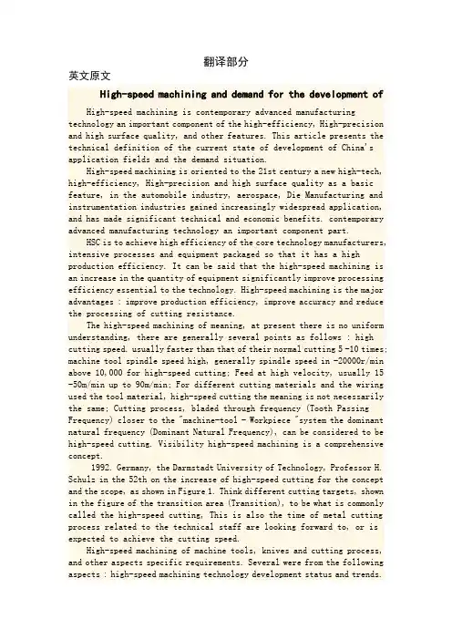
翻译部分英文原文High-speed machining and demand for the development ofHigh-speed machining is contemporary advanced manufacturing technology an important component of the high-efficiency, High-precision and high surface quality, and other features. This article presents the technical definition of the current state of development of China's application fields and the demand situation.High-speed machining is oriented to the 21st century a new high-tech, high-efficiency, High-precision and high surface quality as a basic feature, in the automobile industry, aerospace, Die Manufacturing and instrumentation industries gained increasingly widespread application, and has made significant technical and economic benefits. contemporary advanced manufacturing technology an important component part.HSC is to achieve high efficiency of the core technology manufacturers, intensive processes and equipment packaged so that it has a high production efficiency. It can be said that the high-speed machining is an increase in the quantity of equipment significantly improve processing efficiency essential to the technology. High-speed machining is the major advantages : improve production efficiency, improve accuracy and reduce the processing of cutting resistance.The high-speed machining of meaning, at present there is no uniform understanding, there are generally several points as follows : high cutting speed. usually faster than that of their normal cutting 5 -10 times; machine tool spindle speed high, generally spindle speed in -20000r/min above 10,000 for high-speed cutting; Feed at high velocity, usually 15 -50m/min up to 90m/min; For different cutting materials and the wiring used the tool material, high-speed cutting the meaning is not necessarily the same; Cutting process, bladed through frequency (Tooth Passing Frequency) closer to the "machine-tool - Workpiece "system the dominant natural frequency (Dominant Natural Frequency), can be considered to be high-speed cutting. Visibility high-speed machining is a comprehensive concept.1992. Germany, the Darmstadt University of Technology, Professor H. Schulz in the 52th on the increase of high-speed cutting for the concept and the scope, as shown in Figure 1. Think different cutting targets, shown in the figure of the transition area (Transition), to be what is commonly called the high-speed cutting, This is also the time of metal cutting process related to the technical staff are looking forward to, or is expected to achieve the cutting speed.High-speed machining of machine tools, knives and cutting process, and other aspects specific requirements. Several were from the following aspects : high-speed machining technology development status and trends.At this stage, in order to achieve high-speed machining, general wiring with high flexibility of high-speed CNC machine tools, machining centers, By using a dedicated high-speed milling, drilling. These equipment in common is : We must also have high-speed and high-speed spindle system feeding system, Cutting can be achieved in high-speed process. High-speed cutting with the traditional cutting the biggest difference is that "Machine-tool-workpiece" the dynamic characteristics of cutting performance is stronger influence. In the system, the machine spindle stiffness, grip or form, a long knife set, spindle Broach, torque tool set, Performance high-speed impact are important factors.In the high-speed cutting, material removal rate (Metal Removal Rate, MRR), unit time that the material was removed volume, usually based on the "machine-tool-workpiece" whether Processing System "chatter." Therefore, in order to satisfy the high-speed machining needs, we must first improve the static and dynamic stiffness of machine spindle is particularly the stiffness characteristics. HSC reason at this stage to be successful, a very crucial factor is the dynamic characteristics of the master and processing capability.In order to better describe the machine spindle stiffness characteristics of the project presented new dimensionless parameter - DN value, used for the evaluation of the machine tool spindle structure on the high-speed machining of adaptability. DN value of the so-called "axis diameter per minute speed with the product." The newly developed spindle machining center DN values have been great over one million. To reduce the weight bearing, but also with an array of steel products than to the much more light ceramic ball bearings; Bearing Lubrication most impressive manner mixed with oil lubrication methods. In the field of high-speed machining. have air bearings and the development of magnetic bearings and magnetic bearings and air bearings combined constitute the magnetic gas / air mixing spindle.Feed the machine sector, high-speed machining used in the feed drive is usually larger lead, multiple high-speed ball screw and ball array of small-diameter silicon nitride (Si3N4) ceramic ball, to reduce its centrifugal and gyroscopic torque; By using hollow-cooling technology to reduce operating at high speed ball screw as temperature generated by the friction between the lead screw and thermal deformation.In recent years, the use of linear motor-driven high-speed system of up to'' Such feed system has removed the motor from workstations to Slide in the middle of all mechanical transmission links, Implementation of Machine Tool Feed System of zero transmission. Because no linear motor rotating components, from the role of centrifugal force, can greatly increase the feed rate. Linear Motor Another major advantage of the trip is unrestricted. The linear motor is a very time for a continuous machine shop in possession of the bed. Resurfacing of the very meeting where avery early stage movement can go, but the whole system of up to the stiffness without any influence. By using high-speed screw, or linear motor can greatly enhance machine system of up to the rapid response. The maximum acceleration linear motors up to 2-10G (G for the acceleration of gravity), the largest feed rate of up to 60 -200m/min or higher.2002 world-renowned Shanghai Pudong maglev train project of maglev track steel processing, Using the Shenyang Machine Tool Group Holdings Limited McNair friendship company production plants into extra-long high-speed system for large-scale processing centers achieve . The machine feeding system for the linear guide and rack gear drive, the largest table feed rate of 60 m / min, Quick trip of 100 m / min, 2 g acceleration, maximum speed spindle 20000 r / min, the main motor power 80 kW. X-axis distance of up to 30 m, 25 m cutting long maglev track steel error is less than 0.15 mm. Maglev trains for the smooth completion of the project provided a strong guarantee for technologyIn addition, the campaign machine performance will also directly affect the processing efficiency and accuracy of processing. Mold and the free surface of high-speed machining, the main wiring with small cut deep into methods for processing. Machine requirements in the feed rate conditions, should have high-precision positioning functions andhigh-precision interpolation function, especially high-precision arc interpolation. Arc processing is to adopt legislation or thread milling cutter mold or machining parts, the essential processing methods. Cutting Tools Tool Material developmenthigh-speed cutting and technological development of the history, tool material is continuous progress of history. The representation ofhigh-speed cutting tool material is cubic boron nitride (CBN). Face Milling Cutter use of CBN, its cutting speed can be as high as 5000 m / min, mainly for the gray cast iron machining. Polycrystalline diamond (PCD) has been described as a tool of the 21st century tool, It is particularly applicable to the cutting aluminum alloy containing silica material, which is light weight metal materials, high strength, widely used in the automobile, motorcycle engine, electronic devices shell, the base, and so on. At present, the use of polycrystalline diamond cutter Face Milling alloy, 5000m/min the cutting speed has reached a practical level. In addition ceramic tool also applies to gray iron of high-speed machining; Tool Coating : CBN and diamond cutter, despite good high-speed performance, but the cost is relatively high. Using the coating technology to make cutting tool is the low price, with excellent mechanical properties, which can effectively reduce the cost. Now high-speed processing of milling cutter, with most of the wiring between the Ti-A1-N composite technology for the way of multi-processing, If present in the non-ferrous metal or alloy material dry cutting, DLC (Diamond Like Carbon) coating on thecutter was of great concern. It is expected that the market outlook is very significant;Tool clamping system : Tool clamping system to support high-speed cutting is an important technology, Currently the most widely used is a two-faced tool clamping system. Has been formally invested as a commodity market at the same clamping tool system are : HSK, KM, Bigplus. NC5, AHO systems. In the high-speed machining, tool and fixture rotary performance of the balance not only affects the precision machining and tool life. it will also affect the life of machine tools. So, the choice of tool system, it should be a balanced selection of good products.Process ParametersCutting speed of high-speed processing of conventional shear velocity of about 10 times. For every tooth cutter feed rate remained basically unchanged, to guarantee parts machining precision, surface quality and durability of the tool, Feed volume will also be a corresponding increase about 10 times, reaching 60 m / min, Some even as high as 120 m / min. Therefore, high-speed machining is usually preclude the use of high-speed, feed and depth of cut small cutting parameters. Due to the high-speed machining cutting cushion tend to be small, the formation of very thin chip light, Cutting put the heat away quickly; If the wiring using a new thermal stability better tool materials and coatings, Using the dry cutting process for high-speed machining is the ideal technology program. High-speed machining field of applicationFlexible efficient production lineTo adapt to the needs of new models, auto body panel molds andresin-prevention block the forming die. must shorten the production cycle and reduce the cost of production and, therefore, we must make great efforts to promote the production of high-speed die in the process. SAIC affiliated with the company that : Compared to the past, finishing, further precision; the same time, the surface roughness must be met, the bending of precision, this should be subject to appropriate intensive manual processing. Due to the extremely high cutting speed, and the last finishing processes, the processing cycle should be greatly reduced. To play for machining centers and boring and milling machining center category represented by the high-speed machining technology and automatic tool change function of distinctions Potential to improve processing efficiency, the processing of complex parts used to be concentrated as much as possible the wiring process, that is a fixture in achieving multiple processes centralized processing and dilute the traditional cars, milling, boring, Thread processing different cutting the limits of technology, equipment and give full play to the high-speed cutting tool function, NC is currently raising machine efficiency and speed up product development in an effective way. Therefore, the proposed multi-purpose tool of the new requirements call for a tool to complete different partsof the machining processes, ATC reduce the number of ATC to save time, to reduce the quantity and tool inventory, and management to reduce production costs. More commonly used in a multifunctional Tool, milling, boring and milling, drilling milling, drilling-milling thread-range tool. At the same time, mass production line, against the use of technology requires the development of special tools, tool or a smart composite tool, improve processing efficiency and accuracy and reduced investment. In the high-speed cutting conditions, and some special tools can be part of the processing time to the original 1 / 10 below, results are quite remarkable. HSC has a lot of advantages such as : a large number of materials required resection of the workpiece with ultrafine, thin structure of the workpiece, Traditionally, the need to spend very long hours for processing mobile workpiece and the design of rapid change, short product life cycle of the workpiece, able to demonstrate high-speed cutting brought advantages.中文译文高速切削加工的发展及需求高速切削加工是当代先进制造技术的重要组成部分,拥有高效率、高精度及高表面质量等特征。
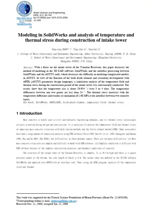
http://kkb.hhu.e e-mail: wse@.cn Water Science and Engineering, 2009, 2(1): 95-102doi:10.3882/j.issn.1674-2370.2009 .01.009Modeling in SolidWorks and analysis of temperature and thermal stress during construction of intake towerHong-yang ZHANG* †1, Tong-chun LI1, Zong-kun LI21. College of Water Conservancy and Hydropower Engineering, Hohai University, Nanjing 210098, P. R. China2. School of Water Conservancy and Environment Engineering, Zhengzhou University,Zhengzhou 450002, P R. ChinaAbstract:With a focus on the intake tower of the Yanshan Reservoir, this paper discusses themethod of modeling in the 3D CAD software SolidWorks and the interface processing betweenSolidWorks and the ANSYS code, which decreases the difficulty in modeling complicated modelsin ANSYS. In view of the function of the birth-death element and secondary development withAPDL (ANSYS parametric design language), a simulation analysis of the temperature field andthermal stress during the construction period of the intake tower was conveniently conducted. Theresults show that the temperature rise is about 29.934 〇C over 3 or 4 days. The temperaturedifferences between any two points are less than 24 ^. The thermal stress increases with thetemperature difference and reaches its maximum of 1.68 MPa at the interface between two concretelayers.Key words: SolidWorks; ANSYS;APDL; birth-death element; temperature field; thermal stress1 IntroductionMass concrete is widely used in civil and hydraulic engineering nowadays, and its thermal stress increasingly attracts attention during design and construction. It is necessary to analyze the temperature field and thermal stress of important mass concrete structures with both routine methods and the finite element method (FEM). Some researchers have done a large amount of simulation analyses using FEM software (Tatro 1985; Barrett et al. 1992; Kawaguchi and Nakane 1996; Zhu and Xu 2001; Zhu 2006), but difficulties in these methods remain. There are two main difficulties: (1) Most mass concrete structures are complex and difficult to model with FEM software. (2) Complete simulation is difficult with FEM software because of the complex construction processes and boundary conditions of concrete.The structure of the intake tower of the Yanshan Reservoir is complex. It is 34.5 m high and there is a square pressure tunnel at the bottom, the side length of which is 6 m. The intake tower was modeled in the 3D CAD software SolidWorks and imported into ANSYS with an interface tool. Then, using the APDL program, analysis of the temperature field and thermalThis work was supported by the Natural Science Foundation of Henan Province (Grant No. 511050100).†Corresponding author (e-mail: zhybryant@)Received Nov. 11, 2008; accepted Jan. 15, 200996 Hong-Yang ZHANG et al. Water Science and Engineering, Mar. 2009, Vol. 2, No. 1,95-102Fig. 2 Cross section stress during construction was conducted.2 Modeling in SolidWorks and interface processing between SolidWorks and ANSYS2.1 Modeling in SolidWorksSolidWorks is a CAD/CAE/CAM/PDM desktop system, and the first 3D mechanical CAD software in Windows developed by the SolidWorks company. It provides product-level automated design tools (Liu and Ren 2005).The outside structure of the intake tower is simple but the internal structure is relatively complex. Therefore, the process of modeling is undertaken from the inside to the outside. The integrated and internal models of the intake tower are shown in Fig. 1 and Fig. 2.Fig. 1 Integrated model2.2 Interface processing between SolidWorks and ANSYSANSYS is a type of large universal finite element software that has a powerful ability to calculate and analyze aspects of structure, thermal properties, fluid, electromagnetics, acoustics and so on. In addition, the interface of ANSYS can be used to import the CAD model conveniently (Zhang 2005), which greatly reduces the difficulties of dealing with complex models. The interface tools are given in Table 1.After modeling in SolidWorks, it is necessary to save the model as a type of Parasolid (*x_t) so as to import it into ANSYS correctly. Then, in ANSYS, the importing of the model is completed with the command “PARAIN, Name, Extension, Path, Entity, FMT, Scale” or the choice of “File^Import^PARA...” in the GUI interface. There are two means of importing: selecting or not selectin g “Allow Defeaturing”, the differences of which are shown in Fig. 3 and Fig. 4.⑴d rFig. 3 Importing with defeaturing Fig. 4Importing without defeaturing3 Analysis of temperature field of intake towerThe temperature analysis of the intake tower during the construction period involves aspects of the temperature field and thermal stress. The calculation must deal with the problems of simulation of layered construction, dynamic boundary conditions, hydration heat, dynamic elasticity modulus, autogenous volume deformation of concrete and thermal creep stress, which are difficult to simulate directly in ANSYS. APDL is a scripting language based on the style of parametric variables. It is used to reduce a large amount of repetitive work in analysis (Gong and Xie 2004). This study carried out a simulation analysis of the temperature field considering nearly all conditions of construction, using the birth-death element and programming with APDL.3.1 Solving temperature field principle3.1.1 Unsteady temperature field analysisThe temperature of concrete changes during the construction period dueto the effect of hydration heat of cement. This problem can be expressed as a heat conduction problem with internal heat sources in the area. The unsteady temperature field T(x,y,z,T) is written as (Zhu 1999):dT X f d2T d2T d2T=---- ---- 1--- 1 --dr c^yd:x2dy2dz2where 义 is the thermal conductivity of concrete, c is the specific heat of concrete, p is the density of concrete, 0 is the adiabatic temperature rise of concrete, and T is the age of concrete.In the 3D unsteady temperature field analysis, the functional form I e (T) iswhere AR is a subfield of unit e; AD is the area on surface D, which is only in boundaryHong-Yang ZHANG et al. Water Science and Engineering, Mar. 2009, Vol. 2, No. 1,95-102 97(3)where ? is the pouring time. The conversion between Q and 6 isadr cpThe boundary conditions involve the laws of interaction between concrete and the surrounding medium. When concreteis exposed to the air, the boundary condition is,5T、(4)-Mdn(5)T = 26.1 - 25.1cos284 (?-79) (6)units; P=——;P is the exothermic coefficient; the thermal diffusivity a =——;and T a is cp cpthe air temperature.3.1.2 Initial conditions and boundary conditions of concreteThe initial conditions are the distribution laws of the initial transient temperature of internal concrete. The calculated initial temperature of concrete is 10 ^.The index formula of hydration heat of cement isQ(?) =71 610[1 - exp(-0.36?)]where n is the normal direction. Both 7^ and P are constants or variables (Ashida and Tauchert 1998; Lin and Cheng 1997).During the maintenance period, the insulation materials of concrete are steel formworks and straws, and the exothermic coefficient of the outer surface is reduced as equivalent processing. The exothermic coefficients of the steel formwork and the straw are 45 kJ/(m2*h’C) and 10 kJ/(m2*h’C), respectively.Based on the local temperature during construction, the following formula can be fittedaccording to the temperature variation curve:3.2 Analysis of temperature field in ANSYSThe simulation scheme of layered construction, which is based on the real construction scheme, is shown in Table 2. The pouring days in Table 2 are all the total days of construction for each layer. A layer is not poured until the former layer is poured.98 Hong-Yang ZHANG et al. Water Science and Engineering, Mar. 2009, Vol. 2, No. 1,95-102Hong-Yang ZHANG et al. Water Science and Engineering, Mar. 2009, Vol. 2, No. 1,95-102 99temperatures and the temperature curves are given in Table 3 and Fig. 5, respectively.Fig. 5 Maximum temperature curves Fig. 5 shows that the maximumtemperature of each layer occurs on the 3rd or 4th day after pouring, and then the temperature decreases with time, which is consistent with related literature (Lin and Cheng 1997; Luna and Wu 2000; Wu and Luna 2001). In Fig. 5, the numbers of feature points from 2 to 8 are corresponding to their maximum temperature curves from Nodetemp 2 to Nodetemp 8, and the curve of Nodetemp 9 is the air temperature curve. Feature point 8, the maximum temperature of which is 29.934 °C, occurring on the 206th day of the total construction period, shows the maximum temperature rise during the construction period. Feature point 4, the coordinates of which are (16.4, 16.0, 5.0), shows the maximum temperature difference of 23.534 °C.4 Analysis of thermal stress of intake towerExpansion or contraction of the structure occurs during heating and cooling. If the expansion or contraction of different parts is inconsistent, then thermal stress occurs. The indirect method was adopted in this study: the temperature of nodes was first obtained in analysis of the temperature field, and then applied to the structure as a body load.4.1 Selection of calculating parametersThe parameters of concrete are given in Table 4. The elasticity modulus is尽=3.6x10¹⁰[1-exp(-0.40’。

机械工程专业外文文献及翻译文献一(外文标题)
摘要:
该文献研究了机械工程领域中的某个具体问题。
通过实验方法和数学模型的分析,作者得出了一些有意义的结论。
本文介绍了作者的研究方法和结果,并讨论了其在机械工程领域的应用前景。
翻译:
(将文献的主要内容用简洁准确的语言翻译成中文)
文献二(外文标题)
摘要:
该文献探讨了机械工程领域中的另一个重要问题。
通过实证分析和理论推导,作者提出了解决方案,并对其进行了验证。
本文阐述了作者的方法和实验结果,并探讨了其在实践中的应用潜力。
翻译:
(将文献的主要内容用简洁准确的语言翻译成中文)
文献三(外文标题)
摘要:
该文献研究了机械工程领域中的另一个新颖课题。
作者通过数
值模拟和实验验证,得出了一些有趣的发现。
本文介绍了作者的研
究过程和结果,并讨论了其对机械工程领域的影响。
翻译:
(将文献的主要内容用简洁准确的语言翻译成中文)
总结
本文档介绍了三篇机械工程专业的外文文献,包括摘要和翻译。
这些文献都对机械工程领域中的不同问题进行了研究,并提出了相
关的解决方案和发现。
希望这些文献能为机械工程专业的学生和研
究人员提供有价值的参考和启发。
机械设计制造及其自动化军训及军事理论Military Training and Military Theory计算机实用基础2 Introduction to Computer Application大学英语College English体育Physical Education工科数学分析2 Advanced Mathematics代数与几何 2 Linear Algebra Advanced Algebra and Geometry思想道德修养与法律基础Ideological and Moral Cultivation and Law Basics大学英语College English体育大学物理2 College Physics工科数学分析2C语言程序设计 C Language中国近现代史纲要Modern History of China法语二外(上)The Second Foreign Language French工业造型设计Modeling Design of Industrial Products大学英语College English大学物理2 College Physics大学物理实验1 Experiment in College Physics概率论与数理统计Probability Theory & Mathematical Statistics电工技术1 Electrical Engineering电工与电子技术综合实验1 Experiment for Electrical and Electronic Engineering工程图学(CAD)1 Mechanical Graphing理论力学1 Theoretical Mechanics工程力学实验1 Experiment for Engineering Mechanics毛泽东思想、邓小平理论和“三个代表”重要思想概论Introduction to Mao Zedong Thoughts, Deng Xiaoping Theory and the Important Thought of "Three Represents"文化素质教育系列讲座Cultural quality education lectures体育西方文明简史History of western civilization Introduction to Functional Materials机械原理课程设计Course Exercise of Mechanical Principle工程训练(金工实习)engineering training Metal Working Practice大学物理实验1电子技术1 Electronic Engineering电工与电子技术综合实验1机械原理Principle of Mechanics Mechanical Principles工程图学(CAD)1工程力学实验(材力)1材料力学1 Mechanics of Materials马克思主义基本原理Principles of Marxism文化素质教育系列讲座文化素质教育系列讲座体育项目管理Project Management法语二外(下)法语入门1机械设计课程设计Course Exercise in Mechanical Design工程训练(电子工艺实习)electronic process practice Practice on Electronic Working Techniques互换性与测量技术基础Basic Technology of Exchangeability Measurement工程流体力学Engineering Fluid Mechanics自动控制原理3 Automatic Control Theory电工学新技术实践The new technology of electronics practice机械设计Mechanical Design工程材料成型技术基础Engineering material molding technology机械工程材料Engineering Materials文化素质教育系列讲座文化素质教育系列讲座创新设计与制作Innovation design and production复变函数与积分变换Complex Function Functions of Complex V ariables & Integral Transformation社会热点问题评价evaluation of social issues知识产权"Intellectual Property Law"认识实习Cognition Practice制造系统自动化技术Automation of Mechanical Manufacture System传热学Heat Transfer文化素质教育系列讲座机电控制系统分析与设计Mechanical-Electrical Control system数控技术Numerical Control Technology机械制造装备设计Machinery manufacturing equipment design液压传动Hydraulic Transmission测试技术与仪器Measurement Fundamentals & Meter Design Measurement Fundamentals & Meter Design机械制造技术基础foundation of machine manufacturing technology综合课程设计1 Comprehensive Course Exercise生产实习Production Practice Field Practice现代机械设计方法The modern machinery design method机械动态设计Mechanical Dynamic Design机械结构有限元分析Finite Element of Mechanical Structures Finite Element Analysis and Programming Finite Element Analysis for Mechanical Structures机电系统智能化控制技术(双语Mechanical and electrical system intelligent control technology 综合课程设计2机械优化设计Optimum Design of MachineryMechanical Optimum Design毕业设计Graduation Thesis工程测试技术Engineering Testing Technique。
Frictionally excited thermoelastic instability in disc brakes—Transientproblem in the full contact regimeAbstractExceeding the critical sliding velocity in disc brakes can cause unwanted forming of hot spots, non-uniform distribution of contact pressure, vibration, and also, in many cases, permanent damage of the disc. Consequently, in the last decade, a great deal of consideration has been given to modeling methods of thermo elastic instability (TEI), which leads to these effects. Models based on the finite element method are also being developed in addition to the analytical approach. The analytical model of TEI development described in the paper by Lee and Barber [Frictionally excited thermo elastic instability in automotive disk brakes. ASME Journal of Tribology 1993;115:607–14] has been expanded in the presented work. Specific attention was given to the modification of their model, to catch the fact that the arc length of pads is less than the circumference of the disc, and to the development of temperature perturbation amplitude in the early stage of breaking, when pads are in the full contact with the disc. A way is proposed how to take into account both of the initial non-flatness of the disc friction surface and change of the perturbation shape inside the disc in the course of braking.Keywords: Thermo elastic instability; TEI; Disc brake; Hot spots1. IntroductionFormation of hot spots as well as non-uniform distribution of the contact pressure is an unwanted effect emerging in disc brakes in the course of braking or during engagement of a transmission clutch. If the sliding velocity is high enough, this effect can become unstable and can result in disc material damage, frictional vibration, wear, etc. Therefore, a lot of experimental effort is being spent to understand better this effect (cf. Refs.) or to model it in the most feasible fashion. Barber described the thermo elastic instability (TEI)as the cause of the phenomenon. Later Dow and Burton and Burton et al.introduced a mathematical model to establish critical sliding velocity for instability, where two thermo elastic half-planes are considered in contact along their common interface. It is in a work by Lee and Barber that the effect of the thickness was considered and that a model applicable for disc brakes was proposed. Lee and Barber’s model is made up with a metallic layer sliding between twohalf-planes of frictional material. Only recently a parametric analysis of TEI in disc brakes was made or TEI in multi-disc clutches and brakes was modeled. The evolution of hot spots amplitudes has been addressed in Refs. Using analytical approach or the effect of intermittent contact was considered. Finally, the finite element method was also applied to render the onset of TEI (see Ref.).The analysis of nonlinear transient behavior in the mode, when separated contact regions occur, is even accomplished in Ref. As in the case of other engineering problems of instability, it turns out that a more accurate prediction by mathematical modeling is often questionable. This is mainly imparted by neglecting various imperfections and random fluctuations or by the impossibility to describe all possible influences appropriately. Therefore, some effort aroused to interpret results of certain experiments in addition to classical TEI (see, e.g.Ref).This paper is related to the work by Lee and Barber [7].Using an analytical approach, it treats the inception of TEI and the development of hot spots during the full contact regime in the disc brakes. The model proposed in Section 2 enables to cover finite thickness of both friction pads and the ribbed portion of the disc. Section 3 is devoted to the problems of modeling of partial disc surface contact with the pads. Section 4 introduces the term of ‘‘thermal capacity of perturbation’’ emphasizing its association with the value of growth rate, or the sliding velocity magnitude. An analysis of the disc friction surfaces non-flatness and its influence on initial amplitude of perturbations is put forward in the Section 5. Finally, the Section 6 offers a model of temperature perturbation development initiated by the mentioned initial discnon-flatness in the course of braking. The model being in use here comes from a differential equation that covers the variation of the‘‘thermal capacity’’ during the full contact regime of the braking.2. Elaboration of Lee and Barber modelThe brake disc is represented by three layers. The middle one of thickness 2a3 stands for the ribbed portion of the disc with full sidewalls of thickness a2 connected to it. The pads are represented by layers of thickness a1, which are immovable and pressed to each other by a uniform pressure p. The brake disc slips in between these pads at a constant velocity V.We will investigate the conditions under which a spatially sinusoidal perturbation in the temperature and stress fields can grow exponentially with respect to the time in a similar manner to that adopted by Lee and Barber. It is evidenced in their work [7] that it is sufficient to handle only the antisymmetric problem. The perturbations that are symmetric with respect to the midplane of the disc can grow at a velocity well above the sliding velocity V thus being made uninteresting.Let us introduce a coordinate system (x1; y1)fixed to one of the pads (see Fig. 1) thepoints of contact surface between the pad and disc having y1 = 0. Furthermore, let acoordinate system (x2; y2)be fixed to the disc with y2=0 for the points of the midplane. We suppose the perturbation to have a relative velocity ci with respect to the layer i, and the coordinate system (x; y)to move together with the perturbated field. Then we can writeV = c1 -c2; c2 = c3; x = x1 -c1t = x2 -c2t,x2 = x3; y = y2 =y3 =y1 + a2 + a3.We will search the perturbation of the uniform temperature field in the formand the perturbation of the contact pressure in the formwhere t is the time, b denotes a growth rate, subscript I refers to a layer in the model, and j =-1½is the imaginary unit. The parameter m=m(n)=2pin/cir =2pi/L, where n is the number of hot spots on the circumference of the disc cir and L is wavelength of perturbations. The symbols T0m and p0m in the above formulae denote the amplitudes of initial non-uniformities (e.g. fluctuations). Both perturbations (2) and (3) will be searched as complex functions their real part describing the actual perturbation of temperature or pressure field.Obviously, if the growth rate b<0, the initial fluctuations are damped. On the other hand, instability develops ifB〉0.2.1. Temperature field perturbationHeat flux in the direction of the x-axis is zero when the ribbed portion of the disc is considered. Next, let us denote ki = Ki/Qicpi coefficient of the layer i temperature diffusion. Parameters Ki, Qi, cpi are, respectively, the thermal conductivity, density and specific heat of the material for i =1,2. They have been re-calculated to the entire volume of the layer (i = 3) when the ribbed portion of the disc is considered. The perturbation of the temperature field is the solution of the equationsWith and it will meet the following conditions:1,The layers 1 and 2 will have the same temperature at the contact surface2,The layers 2 and 3 will reach the same temperature and the same heat flux in the direction y,3,Antisymmetric condition at the midplaneThe perturbations will be zero at the external surface of a friction pad(If, instead, zero heat flux through external surface has been specified, we obtain practically identical numerical solution for current pads).If we write the temperature development in individual layers in a suitable formwe obtainwhereand2.2. Thermo elastic stresses and displacementsFor the sake of simplicity, let us consider the ribbed portion of the disc to be isotropic environment with corrected modulus of elasticity though, actually, the stiffness of this layer in the direction x differs from that in the direction y. Such simplification is, however, admissible as the yielding central layer 3 practically does not take effect on the disc flexural rigidity unlike full sidewalls (layer 2). Given a thermal field perturbation, we can express the stress state and displacements caused by this perturbation for any layer. The thermo elastic problem can be solved by superimposing a particular solution on the general isothermal solution. We look for the particular solution of a layer in form of a strain potential. The general isothermal solution is given by means of the harmonic potentials after Green and Zerna (see Ref.[18]) and contains four coefficients A, B, C, D for every layer. The relateddisplacement and stress field components are written out in the Appendix A.在全接触条件下,盘式制动器摩擦激发瞬态热弹性不稳定的研究摘要超过临界滑动盘式制动器速度可能会导致形成局部过热,不统一的接触压力,振动分布,而且,在多数情况下,会造成盘式制动闸永久性损坏。
利用CAD / CAM/ CAE系统开发操纵机器人H.S.李*,S.E.张华为技术学院,电力机械工程,云林,台湾,中国摘要在这项研究中,需要开发用于机器人操作臂的CAD/CAE/CAM集成系统。
通过变换矩阵,利用D-H坐标系变换方法对机器人的位姿进行分析,我们使用MATAB软件对其进行计算。
一般来说,利用PRO/E对机械臂的参数进行实体化建模,用Pro / Mechanical软体模拟动态仿真和工作空间,MasterCAM用来实现切削模拟仿真,而最终的模型用CNC数控铣床制造出来。
这样,一个用于机器人操作臂的CAD/CAE/CAM集成系统便开发出来了。
我们用一个范例来验证这种设计,分析以及制造的结果的正确性。
该集成系统不仅促进机器人的生产自动化功能,而且还简化了机械臂的CAD / CAE / CAM的分析过程。
这种集成系统是用于开发一个实用的计算机辅助机构设计课程的教学辅助工具。
©2003由Elsevier B.V.出版关键词:CAD / CAE/ CAM;机械臂;Denavit,Hartenberg坐标系变换引言许多研究已涉及到的CAD / CAE/ CAM集成系统的原理。
吕[1]讨论了平面五杆受电弓的运动学分析并设计制造了基于此弓的机械手。
通过研究五杆受电弓的运动性能,设计出一款简单的控制器来对机械手进行控制。
李某和陈某[2]描述了一个自动升降轮椅固定装置内的全尺寸货车的开发。
开发的过程中,包括机制的概念设计,运动仿真,工程分析,原型开发和测试。
周[3]使用参数化CAD系统的实体模型表达设计理念。
首先开发的是模具,其次是基于CAM系统的模型。
通过与产业界的合作,对试模调整,粉末形成,烧结,烧结后处理在专业的粉末冶金工厂进行了实验。
徐[4]在UG2通用CAD / CAM系统的基础上通过将注塑模具的CAD/CAM软件与注塑模具CAE软件集成建立了一个注塑用CAD / CAE/ CAM系统。
机械专业英语词汇中英文对照翻译一览表陶瓷ceramics合成纤维synthetic fibre电化学腐蚀electrochemical corrosion车架automotive chassis悬架suspension转向器redirector变速器speed changer板料冲压sheet metal parts孔加工spot facing machining车间workshop工程技术人员engineer气动夹紧pneuma lock数学模型mathematical model画法几何descriptive geometry机械制图Mechanical drawing投影projection视图view剖视图profile chart标准件standard component零件图part drawing装配图assembly drawing尺寸标注size marking技术要求technical requirements刚度rigidity内力internal force位移displacement截面section疲劳极限fatigue limit断裂fracture塑性变形plastic distortion脆性材料brittleness material刚度准则rigidity criterion垫圈washer垫片spacer直齿圆柱齿轮straight toothed spur gear 斜齿圆柱齿轮helical-spur gear直齿锥齿轮straight bevel gear运动简图kinematic sketch齿轮齿条pinion and rack蜗杆蜗轮worm and worm gear虚约束passive constraint曲柄crank摇杆racker凸轮cams共轭曲线conjugate curve范成法generation method定义域definitional domain值域range导数\\微分differential coefficient求导derivation定积分definite integral不定积分indefinite integral曲率curvature偏微分partial differential毛坯rough游标卡尺slide caliper千分尺micrometer calipers攻丝tap二阶行列式second order determinant 逆矩阵inverse matrix线性方程组linear equations概率probability随机变量random variable排列组合permutation and combination 气体状态方程equation of state of gas动能kinetic energy势能potential energy机械能守恒conservation of mechanical energy动量momentum桁架truss轴线axes余子式cofactor逻辑电路logic circuit触发器flip-flop脉冲波形pulse shape数模digital analogy液压传动机构fluid drive mechanism机械零件mechanical parts淬火冷却quench淬火hardening回火tempering调质hardening and tempering磨粒abrasive grain结合剂bonding agent砂轮grinding wheel后角clearance angle龙门刨削planing主轴spindle主轴箱headstock卡盘chuck加工中心machining center 车刀lathe tool车床lathe钻削镗削bore车削turning磨床grinder基准benchmark钳工locksmith锻forge压模stamping焊weld拉床broaching machine拉孔broaching装配assembling铸造found流体动力学fluid dynamics流体力学fluid mechanics加工machining液压hydraulic pressure切线tangent机电一体化mechanotronics mechanical-electrical integration气压air pressure pneumatic pressure稳定性stability介质medium液压驱动泵fluid clutch液压泵hydraulic pump阀门valve失效invalidation强度intensity载荷load应力stress安全系数safty factor可靠性reliability螺纹thread螺旋helix键spline销pin滚动轴承rolling bearing滑动轴承sliding bearing弹簧spring制动器arrester brake十字结联轴节crosshead联轴器coupling链chain皮带strap精加工finish machining粗加工rough machining变速箱体gearbox casing腐蚀rust氧化oxidation磨损wear耐用度durability随机信号random signal离散信号discrete signal超声传感器ultrasonic sensor 集成电路integrate circuit挡板orifice plate残余应力residual stress套筒sleeve扭力torsion冷加工cold machining电动机electromotor汽缸cylinder过盈配合interference fit热加工hotwork摄像头CCD camera倒角rounding chamfer优化设计optimal design工业造型设计industrial moulding design有限元finite element滚齿hobbing插齿gear shaping伺服电机actuating motor铣床milling machine钻床drill machine镗床boring machine步进电机stepper motor丝杠screw rod导轨lead rail组件subassembly可编程序逻辑控制器Programmable Logic Controller PLC 电火花加工electric spark machining电火花线切割加工electrical discharge wire - cutting 相图phase diagram热处理heat treatment固态相变solid state phase changes有色金属nonferrous metal陶瓷ceramics合成纤维synthetic fibre电化学腐蚀electrochemical corrosion车架automotive chassis悬架suspension转向器redirector变速器speed changer板料冲压sheet metal parts孔加工spot facing machining车间workshop工程技术人员engineer气动夹紧pneuma lock数学模型mathematical model画法几何descriptive geometry机械制图Mechanical drawing投影projection视图view剖视图profile chart标准件standard component零件图part drawing装配图assembly drawing尺寸标注size marking技术要求technical requirements刚度rigidity内力internal force位移displacement截面section疲劳极限fatigue limit断裂fracture塑性变形plastic distortion脆性材料brittleness material刚度准则rigidity criterion垫圈washer垫片spacer直齿圆柱齿轮straight toothed spur gear 斜齿圆柱齿轮helical-spur gear直齿锥齿轮straight bevel gear运动简图kinematic sketch齿轮齿条pinion and rack蜗杆蜗轮worm and worm gear虚约束passive constraint曲柄crank摇杆racker凸轮cams共轭曲线conjugate curve范成法generation method定义域definitional domain值域range导数\\微分differential coefficient求导derivation定积分definite integral不定积分indefinite integral曲率curvature偏微分partial differential毛坯rough游标卡尺slide caliper千分尺micrometer calipers攻丝tap二阶行列式second order determinant 逆矩阵inverse matrix线性方程组linear equations概率probability随机变量random variable排列组合permutation and combination气体状态方程equation of state of gas动能kinetic energy势能potential energy机械能守恒conservation of mechanical energy 动量momentum桁架truss轴线axes余子式cofactor逻辑电路logic circuit触发器flip-flop脉冲波形pulse shape数模digital analogy液压传动机构fluid drive mechanism机械零件mechanical parts淬火冷却quench淬火hardening回火tempering调质hardening and tempering磨粒abrasive grain结合剂bonding agent砂轮grinding wheel Assembly line 组装线Layout 布置图Conveyer 流水线物料板Rivet table 拉钉机Rivet gun 拉钉枪Screw driver 起子Pneumatic screw driver 气动起子worktable 工作桌OOBA 开箱检查fit together 组装在一起fasten 锁紧(螺丝)fixture 夹具(治具)pallet 栈板barcode 条码barcode scanner 条码扫描器fuse together 熔合fuse machine热熔机repair修理operator作业员QC品管supervisor 课长ME 制造工程师MT 制造生技cosmetic inspect 外观检查inner parts inspect 内部检查thumb screw 大头螺丝lbs. inch 镑、英寸EMI gasket 导电条front plate 前板rear plate 后板chassis 基座bezel panel 面板power button 电源按键reset button 重置键Hi-pot test of SPS 高源高压测试Voltage switch of SPS 电源电压接拉键sheet metal parts 冲件plastic parts 塑胶件SOP 制造作业程序material check list 物料检查表work cell 工作间trolley 台车carton 纸箱sub-line 支线left fork 叉车personnel resource department 人力资源部production department生产部门planning department企划部QC Section品管科stamping factory冲压厂painting factory烤漆厂molding factory成型厂common equipment常用设备uncoiler and straightener整平机punching machine 冲床robot机械手hydraulic machine油压机lathe车床planer |plein|刨床miller铣床grinder磨床linear cutting线切割electrical sparkle电火花welder电焊机staker=reviting machine铆合机position职务president董事长general manager总经理special assistant manager特助factory director厂长department director部长deputy manager | =vice manager副理section supervisor课长deputy section supervisor =vice section superisor副课长group leader/supervisor组长line supervisor线长assistant manager助理to move, to carry, to handle搬运be put in storage入库pack packing包装to apply oil擦油to file burr 锉毛刺final inspection终检to connect material接料to reverse material 翻料wet station沾湿台Tiana天那水cleaning cloth抹布to load material上料to unload material卸料to return material/stock to退料scraped |\\'skr?pid|报废scrape ..v.刮;削deficient purchase来料不良manufacture procedure制程deficient manufacturing procedure制程不良oxidation |\\' ksi\\'dei?n|氧化scratch刮伤dents压痕defective upsiding down抽芽不良defective to staking铆合不良embedded lump镶块feeding is not in place送料不到位stamping-missing漏冲production capacity生产力education and training教育与训练proposal improvement提案改善spare parts=buffer备件forklift叉车trailer=long vehicle拖板车compound die合模die locker锁模器pressure plate=plate pinch压板bolt螺栓administration/general affairs dept总务部automatic screwdriver电动启子thickness gauge厚薄规gauge(or jig)治具power wire电源线buzzle蜂鸣器defective product label不良标签identifying sheet list标示单location地点present members出席人员subject主题conclusion结论decision items决议事项responsible department负责单位pre-fixed finishing date预定完成日approved by / checked by / prepared by核准/审核/承办PCE assembly production schedule sheet PCE组装厂生产排配表model机锺work order工令revision版次remark备注production control confirmation生产确认checked by初审approved by核准department部门stock age analysis sheet 库存货龄分析表on-hand inventory现有库存available material良品可使用obsolete material良品已呆滞to be inspected or reworked 待验或重工total合计cause description原因说明part number/ P/N 料号type形态item/group/class类别quality品质prepared by制表notes说明year-end physical inventory difference analysis sheet 年终盘点差异分析表physical inventory盘点数量physical count quantity帐面数量difference quantity差异量cause analysis原因分析raw materials原料materials物料finished product成品semi-finished product半成品packing materials包材good product/accepted goods/ accepted parts/good parts 良品defective product/non-good parts不良品disposed goods处理品warehouse/hub仓库on way location在途仓oversea location海外仓spare parts physical inventory list备品盘点清单spare molds location模具备品仓skid/pallet栈板tox machine自铆机wire EDM线割EDM放电机coil stock卷料sheet stock片料tolerance工差score=groove压线cam block滑块pilot导正筒trim剪外边pierce剪内边drag form压锻差pocket for the punch head挂钩槽slug hole废料孔feature die公母模expansion dwg展开图radius半径shim(wedge)楔子torch-flame cut火焰切割set screw止付螺丝form block折刀stop pin定位销round pierce punch=die button圆冲子shape punch=die insert异形子stock locater block定位块under cut=scrap chopper清角active plate活动板baffle plate挡块cover plate盖板male die公模female die母模groove punch压线冲子air-cushion eject-rod气垫顶杆spring-box eject-plate弹簧箱顶板bushing block衬套insert 入块club car高尔夫球车capability能力parameter参数factor系数phosphate皮膜化成viscosity涂料粘度alkalidipping脱脂main manifold主集流脉bezel斜视规blanking穿落模dejecting顶固模demagnetization去磁;消磁high-speed transmission高速传递heat dissipation热传rack上料degrease脱脂rinse水洗alkaline etch龄咬desmut剥黑膜D.I. rinse纯水次Chromate铬酸处理Anodize阳性处理seal封孔revision版次part number/P/N料号good products良品scraped products报放心品defective products不良品finished products成品disposed products处理品barcode条码flow chart流程表单assembly组装stamping冲压molding成型spare parts=buffer备品coordinate座标dismantle the die折模auxiliary fuction辅助功能poly-line多义线heater band 加热片thermocouple热电偶sand blasting喷沙grit 砂砾derusting machine除锈机degate打浇口dryer烘干机induction感应induction light感应光response=reaction=interaction感应ram连杆edge finder巡边器concave凸convex凹short射料不足nick缺口speck瑕??shine亮班splay 银纹gas mark焦痕delamination起鳞cold slug冷块blush 导色gouge沟槽;凿槽satin texture段面咬花witness line证示线patent专利grit沙砾granule=peuet=grain细粒grit maker抽粒机cushion缓冲magnalium镁铝合金magnesium镁金metal plate钣金lathe车mill锉plane刨grind磨drill铝boring镗blinster气泡fillet镶;嵌边through-hole form通孔形式voller pin formality滚针形式cam driver铡楔shank摸柄crank shaft曲柄轴augular offset角度偏差velocity速度production tempo生产进度现状torque扭矩spline=the multiple keys花键quenching淬火tempering回火annealing退火carbonization碳化tungsten high speed steel钨高速的moly high speed steel钼高速的organic solvent有机溶剂bracket小磁导liaison联络单volatile挥发性resistance电阻ion离子titrator滴定仪beacon警示灯coolant冷却液crusher破碎机阿基米德蜗杆Archimedes worm安全系数safety factor; factor of safety安全载荷safe load凹面、凹度concavity扳手wrench板簧flat leaf spring半圆键woodruff key变形deformation摆杆oscillating bar摆动从动件oscillating follower摆动从动件凸轮机构cam with oscillating follower 摆动导杆机构oscillating guide-bar mechanism 摆线齿轮cycloidal gear摆线齿形cycloidal tooth profile摆线运动规律cycloidal motion摆线针轮cycloidal-pin wheel包角angle of contact保持架cage背对背安装back-to-back arrangement背锥back cone ;normal cone背锥角back angle背锥距back cone distance比例尺scale比热容specific heat capacity闭式链closed kinematic chain闭链机构closed chain mechanism臂部arm变频器frequency converters变频调速frequency control of motor speed 变速speed change变速齿轮change gear change wheel变位齿轮modified gear变位系数modification coefficient标准齿轮standard gear标准直齿轮standard spur gear表面质量系数superficial mass factor表面传热系数surface coefficient of heat transfer 表面粗糙度surface roughness并联式组合combination in parallel并联机构parallel mechanism并联组合机构parallel combined mechanism并行工程concurrent engineering并行设计concurred design, CD不平衡相位phase angle of unbalance不平衡imbalance (or unbalance)不平衡量amount of unbalance不完全齿轮机构intermittent gearing波发生器wave generator波数number of waves补偿compensation参数化设计parameterization design, PD残余应力residual stress操纵及控制装置operation control device槽轮Geneva wheel槽轮机构Geneva mechanism ;Maltese cross 槽数Geneva numerate槽凸轮groove cam侧隙backlash差动轮系differential gear train差动螺旋机构differential screw mechanism差速器differential常用机构conventional mechanism; mechanism in common use车床lathe承载量系数bearing capacity factor承载能力bearing capacity成对安装paired mounting尺寸系列dimension series齿槽tooth space齿槽宽spacewidth齿侧间隙backlash齿顶高addendum齿顶圆addendum circle齿根高dedendum齿根圆dedendum circle齿厚tooth thickness齿距circular pitch齿宽face width齿廓tooth profile齿廓曲线tooth curve齿轮gear齿轮变速箱speed-changing gear boxes齿轮齿条机构pinion and rack齿轮插刀pinion cutter; pinion-shaped shaper cutter 齿轮滚刀hob ,hobbing cutter齿轮机构gear齿轮轮坯blank齿轮传动系pinion unit齿轮联轴器gear coupling齿条传动rack gear齿数tooth number齿数比gear ratio齿条rack齿条插刀rack cutter; rack-shaped shaper cutter齿形链、无声链silent chain齿形系数form factor齿式棘轮机构tooth ratchet mechanism插齿机gear shaper重合点coincident points重合度contact ratio冲床punch传动比transmission ratio, speed ratio传动装置gearing; transmission gear传动系统driven system传动角transmission angle传动轴transmission shaft串联式组合combination in series串联式组合机构series combined mechanism 串级调速cascade speed control创新innovation creation创新设计creation design垂直载荷、法向载荷normal load唇形橡胶密封lip rubber seal磁流体轴承magnetic fluid bearing从动带轮driven pulley从动件driven link, follower从动件平底宽度width of flat-face从动件停歇follower dwell从动件运动规律follower motion从动轮driven gear粗线bold line粗牙螺纹coarse thread大齿轮gear wheel打包机packer打滑slipping带传动belt driving带轮belt pulley带式制动器band brake单列轴承single row bearing单向推力轴承single-direction thrust bearing单万向联轴节single universal joint单位矢量unit vector当量齿轮equivalent spur gear; virtual gear当量齿数equivalent teeth number; virtual number of teeth 当量摩擦系数equivalent coefficient of friction当量载荷equivalent load刀具cutter导数derivative倒角chamfer导热性conduction of heat导程lead导程角lead angle等加等减速运动规律parabolic motion; constant acceleration and deceleration motion等速运动规律uniform motion; constant velocity motion等径凸轮conjugate yoke radial cam等宽凸轮constant-breadth cam等效构件equivalent link等效力equivalent force等效力矩equivalent moment of force等效量equivalent等效质量equivalent mass等效转动惯量equivalent moment of inertia等效动力学模型dynamically equivalent model底座chassis低副lower pair点划线chain dotted line(疲劳)点蚀pitting垫圈gasket垫片密封gasket seal碟形弹簧belleville spring顶隙bottom clearance定轴轮系ordinary gear train; gear train with fixed axes 动力学dynamics动密封kinematical seal动能dynamic energy动力粘度dynamic viscosity动力润滑dynamic lubrication动平衡dynamic balance动平衡机dynamic balancing machine动态特性dynamic characteristics动态分析设计dynamic analysis design动压力dynamic reaction动载荷dynamic load端面transverse plane端面参数transverse parameters端面齿距transverse circular pitch端面齿廓transverse tooth profile端面重合度transverse contact ratio端面模数transverse module端面压力角transverse pressure angle锻造forge对称循环应力symmetry circulating stress对心滚子从动件radial (or in-line ) roller follower对心直动从动件radial (or in-line ) translating follower对心移动从动件radial reciprocating follower对心曲柄滑块机构in-line slider-crank (or crank-slider) mechanism多列轴承multi-row bearing多楔带poly V-belt多项式运动规律polynomial motion多质量转子rotor with several masses惰轮idle gear额定寿命rating life额定载荷load ratingII 级杆组dyad发生线generating line发生面generating plane法面normal plane法面参数normal parameters法面齿距normal circular pitch法面模数normal module法面压力角normal pressure angle法向齿距normal pitch法向齿廓normal tooth profile法向直廓蜗杆straight sided normal worm法向力normal force反馈式组合feedback combining反向运动学inverse ( or backward) kinematics 反转法kinematic inversion反正切Arctan范成法generating cutting仿形法form cutting方案设计、概念设计concept design, CD防振装置shockproof device飞轮flywheel飞轮矩moment of flywheel非标准齿轮nonstandard gear非接触式密封non-contact seal非周期性速度波动aperiodic speed fluctuation非圆齿轮non-circular gear粉末合金powder metallurgy分度线reference line; standard pitch line分度圆reference circle; standard (cutting) pitch circle 分度圆柱导程角lead angle at reference cylinder分度圆柱螺旋角helix angle at reference cylinder分母denominator分子numerator分度圆锥reference cone; standard pitch cone分析法analytical method封闭差动轮系planetary differential复合铰链compound hinge复合式组合compound combining复合轮系compound (or combined) gear train 复合平带compound flat belt复合应力combined stress复式螺旋机构Compound screw mechanism复杂机构complex mechanism杆组Assur group干涉interference刚度系数stiffness coefficient刚轮rigid circular spline钢丝软轴wire soft shaft刚体导引机构body guidance mechanism刚性冲击rigid impulse (shock)刚性转子rigid rotor刚性轴承rigid bearing刚性联轴器rigid coupling高度系列height series高速带high speed belt高副higher pair格拉晓夫定理Grashoff`s law根切undercutting公称直径nominal diameter高度系列height series功work工况系数application factor工艺设计technological design工作循环图working cycle diagram工作机构operation mechanism工作载荷external loads工作空间working space工作应力working stress工作阻力effective resistance工作阻力矩effective resistance moment 公法线common normal line公共约束general constraint公制齿轮metric gears功率power功能分析设计function analyses design 共轭齿廓conjugate profiles共轭凸轮conjugate cam构件link鼓风机blower固定构件fixed link; frame固体润滑剂solid lubricant关节型操作器jointed manipulator惯性力inertia force惯性力矩moment of inertia ,shaking moment 惯性力平衡balance of shaking force惯性力完全平衡full balance of shaking force惯性力部分平衡partial balance of shaking force 惯性主矩resultant moment of inertia惯性主失resultant vector of inertia冠轮crown gear广义机构generation mechanism广义坐标generalized coordinate轨迹生成path generation轨迹发生器path generator滚刀hob滚道raceway滚动体rolling element滚动轴承rolling bearing滚动轴承代号rolling bearing identification code 滚针needle roller滚针轴承needle roller bearing滚子roller滚子轴承roller bearing滚子半径radius of roller滚子从动件roller follower滚子链roller chain滚子链联轴器double roller chain coupling 滚珠丝杆ball screw滚柱式单向超越离合器roller clutch过度切割undercutting函数发生器function generator函数生成function generation含油轴承oil bearing耗油量oil consumption耗油量系数oil consumption factor赫兹公式H. Hertz equation合成弯矩resultant bending moment合力resultant force合力矩resultant moment of force黑箱black box横坐标abscissa互换性齿轮interchangeable gears花键spline滑键、导键feather key滑动轴承sliding bearing滑动率sliding ratio滑块slider环面蜗杆toroid helicoids worm环形弹簧annular spring缓冲装置shocks; shock-absorber灰铸铁grey cast iron回程return回转体平衡balance of rotors混合轮系compound gear train积分integrate机电一体化系统设计mechanical-electrical integration system design机构mechanism机构分析analysis of mechanism机构平衡balance of mechanism机构学mechanism机构运动设计kinematic design of mechanism机构运动简图kinematic sketch of mechanism机构综合synthesis of mechanism机构组成constitution of mechanism机架frame, fixed link机架变换kinematic inversion机器machine机器人robot机器人操作器manipulator机器人学robotics技术过程technique process技术经济评价technical and economic evaluation 技术系统technique system机械machinery机械创新设计mechanical creation design, MCD 机械系统设计mechanical system design, MSD 机械动力分析dynamic analysis of machinery机械动力设计dynamic design of machinery机械动力学dynamics of machinery机械的现代设计modern machine design机械系统mechanical system机械利益mechanical advantage机械平衡balance of machinery机械手manipulator机械设计machine design; mechanical design机械特性mechanical behavior机械调速mechanical speed governors机械效率mechanical efficiency机械原理theory of machines and mechanisms机械运转不均匀系数coefficient of speed fluctuation机械无级变速mechanical stepless speed changes基础机构fundamental mechanism基本额定寿命basic rating life基于实例设计case-based design,CBD基圆base circle基圆半径radius of base circle基圆齿距base pitch基圆压力角pressure angle of base circle基圆柱base cylinder基圆锥base cone急回机构quick-return mechanism急回特性quick-return characteristics急回系数advance-to return-time ratio急回运动quick-return motion棘轮ratchet棘轮机构ratchet mechanism棘爪pawl极限位置extreme (or limiting) position极位夹角crank angle between extreme (or limiting) positions计算机辅助设计computer aided design, CAD计算机辅助制造computer aided manufacturing, CAM计算机集成制造系统computer integrated manufacturing system, CIMS计算力矩factored moment; calculation moment计算弯矩calculated bending moment加权系数weighting efficient加速度acceleration加速度分析acceleration analysis加速度曲线acceleration diagram尖点pointing; cusp尖底从动件knife-edge follower间隙backlash间歇运动机构intermittent motion mechanism减速比reduction ratio减速齿轮、减速装置reduction gear减速器speed reducer减摩性anti-friction quality渐开螺旋面involute helicoid渐开线involute渐开线齿廓involute profile渐开线齿轮involute gear渐开线发生线generating line of involute渐开线方程involute equation渐开线函数involute function渐开线蜗杆involute worm渐开线压力角pressure angle of involute渐开线花键involute spline简谐运动simple harmonic motion键key键槽keyway交变应力repeated stress交变载荷repeated fluctuating load交叉带传动cross-belt drive交错轴斜齿轮crossed helical gears胶合scoring角加速度angular acceleration角速度angular velocity角速比angular velocity ratio角接触球轴承angular contact ball bearing角接触推力轴承angular contact thrust bearing 角接触向心轴承angular contact radial bearing 角接触轴承angular contact bearing铰链、枢纽hinge校正平面correcting plane接触应力contact stress接触式密封contact seal阶梯轴multi-diameter shaft结构structure结构设计structural design截面section节点pitch point节距circular pitch; pitch of teeth节线pitch line节圆pitch circle节圆齿厚thickness on pitch circle节圆直径pitch diameter节圆锥pitch cone节圆锥角pitch cone angle解析设计analytical design紧边tight-side紧固件fastener径节diametral pitch径向radial direction径向当量动载荷dynamic equivalent radial load径向当量静载荷static equivalent radial load径向基本额定动载荷basic dynamic radial load rating径向基本额定静载荷basic static radial load tating径向接触轴承radial contact bearing径向平面radial plane径向游隙radial internal clearance径向载荷radial load径向载荷系数radial load factor径向间隙clearance静力static force静平衡static balance静载荷static load静密封static seal局部自由度passive degree of freedom矩阵matrix矩形螺纹square threaded form锯齿形螺纹buttress thread form矩形牙嵌式离合器square-jaw positive-contact clutch 绝对尺寸系数absolute dimensional factor绝对运动absolute motion绝对速度absolute velocity均衡装置load balancing mechanism抗压强度compression strength开口传动open-belt drive开式链open kinematic chain开链机构open chain mechanism可靠度degree of reliability可靠性reliability可靠性设计reliability design, RD空气弹簧air spring空间机构spatial mechanism空间连杆机构spatial linkage空间凸轮机构spatial cam空间运动副spatial kinematic pair空间运动链spatial kinematic chain 空转idle宽度系列width series框图block diagram雷诺方程Reynolds‘s equation离心力centrifugal force离心应力centrifugal stress离合器clutch离心密封centrifugal seal理论廓线pitch curve理论啮合线theoretical line of action 隶属度membership力force力多边形force polygon力封闭型凸轮机构force-drive (or force-closed) cam mechanism力矩moment力平衡equilibrium力偶couple力偶矩moment of couple连杆connecting rod, coupler连杆机构linkage连杆曲线coupler-curve连心线line of centers链chain链传动装置chain gearing链轮sprocket sprocket-wheel sprocket gear chain wheel联组V 带tight-up V belt联轴器coupling shaft coupling两维凸轮two-dimensional cam临界转速critical speed六杆机构six-bar linkage龙门刨床double Haas planer轮坯blank。
中国地质大学长城学院本科毕业设计外文资料翻译系别:工程技术系专业:机械设计制造及其自动化姓名:黄晓鹏学号: 052116322015 年 4 月 28 日外文资料翻译译文公元前1世纪,中国已推广使用耧,这是世界上最早的条播机具,今仍在北方旱作区应用。
1636年在希腊制成第一台播种机。
1830 年俄国人在畜力多铧犁上制成犁播机。
1860年后,英美等国开始大量生产畜力谷物条播机。
20世纪后相继出现了牵引和悬挂式谷物条播机,以及运用气力排种的播种机。
50年代发展精密播种机。
中国从20世纪50年代引进了谷物条播机、棉花播种机等。
60年代先后研制成悬挂式谷物播种机、离心式播种机、通用机架播种机和气吸式播种机等多种类型,并研制成磨纹式排种器。
到70年代,已形成播种中耕通用机和谷物联合播种机两个系列,同时研制成功了精密播种机。
欧洲第一台播种机于1636年在希腊制成。
1830年,俄国人在畜力多铧犁上加装播种装置制成犁播机。
英、美等国在1860年以后开始大量生产畜力谷物条播机。
20世纪以后相继出现了牵引和悬挂式谷物条播机,以及运用气力排种的播种机。
1958年挪威出现第一台离心式播种机,50年代以后逐步发展各种精密播种机。
中国在20世纪50年代从国外引进谷物条播机、棉花播种机等,60年代先后研制成功悬挂式谷物播种机、离心式播种机、通用机架播种机和气吸式播种机等多种机型,并研制成功了磨纹式排种器。
到70年代,已形成播种中耕通用机和谷物联合播种机两个系列并投入生产。
供谷物、中耕作物、牧草、蔬菜用的各种条播机和穴播机都已得到推广使用。
与此同时,还研制成功了多种精密播种机。
播种机的使用方法播种机具有播种均匀、深浅一致、行距稳定、覆土良好、节省种子、工作效率高等特点。
正确使用播种机应注意掌握以下10要点:1 进田作业前的保养要清理播种箱内的杂物和开沟器上的缠草、泥土,确保状态良好,并对拖拉机及播种机的各传动、转动部位,按说明书的要求加注润滑油,尤其是每次作业前要注意传动链条润滑和张紧情况以及播种机上螺栓的紧固情况。
Unit 1 Metals金属Unit 2 Selection of Construction Materials工程材料的选择淬透性:指在规定条件下,决定钢材淬硬深度和硬度分布的特性。
即钢淬火时得到淬硬层深度大小的能力,它表示钢接受淬火的能力.钢材淬透性好与差,常用淬硬层深度来表示。
淬硬层深度越大,则钢的淬透性越好。
钢的淬透性是钢材本身所固有的属性,它只取决于其本身的内部因素,而与外部因素无关。
钢的淬透性主要取决于它的化学成分,特别是含增大淬透性的合金元素及晶粒度,加热温度和保温时间等因素有关。
淬透性好的钢材,可使钢件整个截面获得均匀一致的力学性能以及可选用钢件淬火应力小的淬火剂,以减少变形和开裂。
淬透性主要取决于其临界冷却速度的大小,而临界冷却速度则主要取决于过冷奥氏体的稳定性,影响奥氏体的稳定性主要是:1。
化学成分的影响碳的影响是主要的,当C%小于1.2%时,随着奥氏体中碳浓度的提高,显著降低临界冷却速度,C曲线右移,钢的淬透性增大;当C%大于时,钢的冷却速度反而升高,C曲线左移,淬透性下降.其次是合金元素的影响,除钴外,绝大多数合金元素溶入奥氏体后,均使C曲线右移,降低临界冷却速度,从而提高钢的淬透性.2。
奥氏体晶粒大小的影响奥氏体的实际晶粒度对钢的淬透性有较大的影响,粗大的奥氏体晶粒能使C曲线右移,降低了钢的临界冷却速度.但晶粒粗大将增大钢的变形、开裂倾向和降低韧性。
3.奥氏体均匀程度的影响在相同冷度条件下,奥氏体成分越均匀,珠光体的形核率就越低,转变的孕育期增长,C曲线右移,临界冷却速度减慢,钢的淬透性越高.4。
钢的原始组织的影响钢的原始组织的粗细和分布对奥氏体的成分将有重大影响。
5。
部分元素,例如Mn,Si等元素对提高淬透性能起到一定作用,但同时也会对钢材带来其他不利的影响。
可锻性(forgeability)金属具有热塑性,在加热状态(各种金属要求温度不同),可以进行压力加工,称为具有可锻性。
数控加工中心技术开展趋势与对策原文来源:Zhao Chang-ming Liu Wang-ju(C Machining Processand equipment,2002,China)一、摘要Equip the engineering level, level of determining the whole national economy of the modernized degree and modernized degree of industry, numerical control technology is it develop new developing new high-tech industry and most advanced industry to equip (such as information technology and his industry, biotechnology and his industry, aviation, spaceflight, etc. national defense industry) last technology and getting more basic most equipment.Numerical control technology is the technology controlled to mechanical movement and working course with digital information, integrated products of electromechanics that the numerical control equipment is the new technology represented by numerical control technology forms to the manufacture industry of the tradition and infiltration of the new developing manufacturing industry,Keywords:Numerical ControlTechnology, E quipment,industry二、译文数控技术和装备开展趋势与对策装备工业的技术水平和现代化程度决定着整个国民经济的水平和现代化程度,数控技术与装备是开展新兴高新技术产业和尖端工业〔如信息技术与其产业、生物技术与其产业、航空、航天等国防工业产业〕的使能技术和最根本的装备。
英文原文Hydraulic SystemHydraulic presser drive and air pressure drive hydraulic fluid as the transmission is made according to the 17th century, Pascal's principle of hydrostatic pressure to drive the development of an emerging technology, the United Kingdo m in 1795 • Braman Joseph (Joseph Braman ,1749-1814), in London water as a medium to form hydraulic press used in industry, the birth of the world's first hydraulic press. Media work in 1905 will be replaced by oil-water and further improved.Hydraulic transmission There are many outstanding advantages, it is widely used, such as general industr- ial use of plastics processing machinery, the pressure of machinery, machine tools, etc.; operating machinery engineering machinery, construction machinery, agricultural machinery, automobiles, etc.; iron and steel indu- stry metallurgical machinery, lifting equipment, such as roller adjustment device; civil water projects with flo- od control and dam gate devices, bed lifts installations, bridges and other manipulation of institutions; speed turbine power plant installations, nuclear power plants, etc.; ship from the deck heavy machinery (winch), the bow doors, bulkhead valve, stern thruster, etc.; special antenna technology giant with control devices, measu- rement buoys, movements such as rotating stage; military-industrial control devices used in artillery, ship anti- rolling devices, aircraft simulation, aircraft retractable landing gear and rudder control devices and other devi- ces.A complete hydraulic system consists of five parts, namely, power components, the implementation of co- mponents, control components, auxiliary components and hydraulic oil.The role of dynamic components of the original motive fluid into mechanical energy to the pressure that the hydraulic system of pumps, it is to power the entire hydraulic system. The structure of the form of hydra- ulic pump gears are generally pump, vane pump and piston pump.Implementation of components (such as hydraulic cylinders and hydraulic motors) which is the pressure of the liquid can be converted to mechanical energy to drive the load for a straight line reciprocating movement or rotational movement.Control components (that is, the various hydraulic valves) in the hydraulic system to control and regulate the pressure of liquid, flow rate and direction. According to the different control functions, hydraulic pressure control valve can be divided into valves, flow control valves and directional control valve. Pressure control valves are divided into benefits flow valve (safety valve), pressure relief valve, sequence valve, pressure relays, etc.; flow control valves including throttle, adjusting the valves, flow diversion valve sets, etc.; directional control valve includes a one-way valve , one-way fluid control valve, shuttle valve, valve and so on. Under the control of different ways, can be divided into the hydraulic valve control switch valve, control valve and set the value of the ratio control valve.Auxiliary components, including fuel tanks, oil filters, tubing and pipe joints, seals, pressure gauge, oil level, such as oil dollars.Hydraulic oil in the hydraulic system is the work of the energy transfer medium, there are a variety of mineral oil, emulsion oil hydraulic molding Hop categories.The role of the hydraulic system is to help humanity work. Mainly by the implementation of components to rotate or pressure into a reciprocating motion.Hydraulic system and hydraulic power control signal is composed of two parts, the signal control of some parts of the hydraulic power used to drive the control valve movement.Part of the hydraulic power means that the circuit diagram used to show the different functions of the interrelationship between components. Containing the source of hydraulic pump, hydraulic motor and auxiliary components; hydraulic control part contains a variety of control valves, used to control the flow of oil, pressure and direction; operative or hydraulic cylinder with hydraulic motors, according to the actual requirements of their choice.In the analysis and design of the actual task, the general block diagram shows the actual operation of equi - pment. Hollow arrow indicates the signal flow, while the solid arrows that energy flow.Basic hydraulic circuit of the action sequence - Control components (two four-way valve) and the spring to reset for the implementation of components (double-acting hydraulic cylinder), as well as the extending and retracting the relief valve opened and closed . For the implementation of components and control components, presentations are based on the corresponding circuit diagram symbols, it also introduced ready made circuit diagram symbols.Working principle of the system, you can turn on all circuits to code. If the first implementation of components numbered 0, the control components associated with the identifier is 1. Out with the implementation of components corresponding to the identifier for the even components, then retracting and implementation of components corresponding to the identifier for the odd components. Hydraulic circuit carried out not only to deal with numbers, but also to deal with the actual device ID, in order to detect system failures.DIN ISO1219-2 standard definition of the number of component composition, which includes the following four parts: device ID, circuit ID, component ID and component ID. The entire system if only one device, device number may be omitted.Practice, another way is to code all of the hydraulic system components for numbers at this time, components and component code should be consistent with the list of numbers. This method is particularly applicable to complex hydraulic control system, each control loop are the corresponding number with the systemWith mechanical transmission, electrical transmission compared to the hydraulic drive has the following advantages:1, a variety of hydraulic components, can easily and flexibly to layout.2, light weight, small size, small inertia, fast response.3, to facilitate manipulation of control, enabling a wide range of stepless speed regulation (speed range of 2000:1).4, to achieve overload protection automatically.5, the general use of mineral oil as a working medium, the relative motion can be self-lubricating surface, long service life;6, it is easy to achieve linear motion /7, it is easy to achieve the automation of machines, when the joint control of the use of electro-hydraulic, not only can achieve a higher degree of process automation, and remote control can be achieved.The shortcomings of the hydraulic system:1, as a result of the resistance to fluid flow and leakage of the larger, so less efficient. If not handled properly, leakage is not only contaminated sites, but also may cause fire and explosion.2, vulnerable performance as a result of the impact of temperature change, it would be inappropriate in the high or low temperature conditions.3, the manufacture of precision hydraulic components require a higher, more expensive and hence the price. 4, due to the leakage of liquid medium and the compressibility and can not be strictly the transmission ratio. 5, hydraulic transmission is not easy to find out the reasons for failure; the use and maintenance requirements for a higher level of technology.In the hydraulic system and its system, the sealing device to prevent leakage of the work of media within and outside the dust and the intrusion of foreign bodies. Seals played the role of components, namely seals. Medium will result in leakage of waste, pollution and environmental machinery and even give rise to malfunctioning machinery and equipment for personal accident. Leakage within the hydraulic system will cause a sharp drop in volumetric efficiency, amounting to less than the required pressure, can not even work. Micro-invasive system of dust particles, can cause or exacerbate friction hydraulic component wear, and further lead to leakage.Therefore, seals and sealing device is an important hydraulic equipment components. The reliability of its机械专业中英文文献翻译work and life, is a measure of the hydraulic system an important indicator of good or bad. In addition to the closed space, are the use of seals, so that two adjacent coupling surface of the gap between the need to control the liquid can be sealed following the smallest gap. In the contact seal, pressed into self-seal-style and self-styled self-tight seal (ie, sealed lips) two.The three hydraulic system diseases1, as a result of heat transmission medium (hydraulic oil) in the flow velocity in various parts of the existence of different, resulting in the existence of a liquid within the internal friction of liquids and pipelines at the sam- e time there is friction between the inner wall, which are a result of hydraulic the reasons for the oil tempera- ture. Temperature will lead to increased internal and external leakage, reducing its mechanical efficiency. At the same time as a result of high temperature, hydraulic oil expansion will occur, resulting in increased com- pression, so that action can not be very good control of transmission. Solution: heat is the inherent characte -ristics of the hydraulic system, not only to minimize eradication. Use a good quality hydraulic oil, hydraulic piping arrangement should be avoided as far as possible the emergence of bend, the use of high-quality pipe and fittings, hydraulic valves, etc.2, the vibration of the vibration of the hydraulic system is also one of its malaise. As a result of hydraulic oil in the pipeline flow of high-speed impact and the control valve to open the closure of the impact of the process are the reasons for the vibration system. Strong vibration control action will cause the system to error, the system will also be some of the more sophisticated equipment error, resulting in system failures. Solutions: hydraulic pipe should be fixed to avoid sharp bends. To avoid frequent changes in flow direction, can not avoid damping measures should be doing a good job. The entire hydraulic system should have a good damping measures, while avoiding the external local oscillator on the system.3, the leakage of the hydraulic system leak into inside and outside the leakage leakage. Leakage refers to the process with the leak occurred in the system, such as hydraulic piston-cylinder on both sides of the leakage, the control valve spool and valve body, such as between the leakage. Although no internal leakage of hydra- ulic fluid loss, but due to leakage, the control of the established movements may be affected until the cause system failures. Outside means the occurrence of leakage in the system and the leakage between the external environment. Direct leakage of hydraulic oil into the environment, in addition to the system will affect the working environment, not enough pressure will cause the system to trigger a fault. Leakage into the enviro- nment of the hydraulic oil was also the danger of fire. Solution: the use of better quality seals to improve the machining accuracy of equipment.Another: the hydraulic system for the three diseases, it was summed up: "fever, with a father拉稀" (This is the summary of the northeast people). Hydraulic system for the lifts, excavators, pumping station, dynamic, crane, and so on large-scale industry, construction, factories, enterprises, as well as elevators, lifting platforms, Deng Axle industry and so on.Hydraulic components will be high-performance, high-quality, high reliability, the system sets the direction of development; to the low power, low noise, vibration, without leakage, as well as pollution control, water-based media applications to adapt to environmental requirements, such as the direction of development; the development of highly integrated high power density, intelligence, mechatronics and micro-light mini-hydraulic components; active use of new techniques, new materials and electronics, sensing and other high-tech.Hydraulic coupling to high-speed high-power and integrated development of hydraulic transmission equ- ipment, development of water hydraulic coupling medium speed and the field of automotive applications to develop hydraulic reducer, improve product reliability and working hours MTBF; hydraulic torque converter to the development of high-power products, parts and components to improve the manufacturing process tech -nology to improve reliability, promote computer-aided technology, the development of hydraulic torque con- verter and power shift transmission technology supporting the use of ; Clutch fluid viscosity should increase the quality of products, the formation of bulk to the high-power and high-speed direction.Pneumatic Industry:Products to small size, light weight, low power consumption, integrated portfolio of development, the implementation of the various types of components, compact structure, high positioning accuracy of the direction of development; pneumatic components and electronic technology, to the intelligent direction of development; component performance to high-speed, high-frequency, high-response, high-life, high temp- erature, high voltage direction, commonly used oil-free lubrication, application of new technology, new technology and new materials.(1)used high-pressure hydraulic components and the pressure of continuous work to reach 40Mpa, the maximum pressure to achieve instant 48Mpa;(2) diversification of regulation and control;(3) to further improve the regulation performance, increase the efficiency of the powertrain;(4) development and mechanical, hydraulic, power transmission of the composite portfolio adjustment gear;(5) development of energy saving, energy efficient system function;(6) to further reduce the noise;(7) Application of Hydraulic Cartridge V alves thread technology, compact structure, to reduce the oil spill Water-based hydraulic systemsWater-based hydraulic systems traditionally have been used in hot-metal areas of steel mills. The obvious advantage of water systems in these industries is their fire resistance. Water-based hydraulic systems also have obvious cost advantages over oil-based fluid. First, non-toxic, biodegradable synthetic additives for water cost $5 to $6 per gallon. One gallon of concentrate can make 20 gallons of a 5% solution, so the cost of water-based hydraulic fluid actually can be less than 30 cents per gallon.Considering the costs associated with preventing and cleaning up environmental contamination, water-based hydraulic systems hold the potential for tremendous cost savings at the plant level. Oil that has leaked already becomes a very important problem. It must be collected, properly contained. Water containing synthetic additives, however, can by dumped into plant effluent systems.Cost savings at the plant level don't stop at the lower cost of the fluid and its disposal. Because water-based hydraulic fluid consists of 10 parts water and one part synthetic additive, 5 gallons of additive mixes with water to make 100 gallons of water-based fluid. A 50gallon container is certainly easier to handle than two 55-gallon drums, so warehousing is simpler, cleaner, and less cluttered. Transportation costs also are lower.Other potential plant-wide savings include improved safety for workers because the water-based fluid is non-toxic as well as non-flammable. These attributes can reduce plant insurance rates. Spills cost less to clean up because granular absorbents or absorbent socks are unnecessary. Water is "hot" againThe oil embargo in the 1970s sparked interest in water-based fluids as a less-costly alternative to oils. Even the most expensive water additives became attractive when designers learned that one gallon of concentrate would make 20 gallons of fluid.As oil prices gradually dropped, so did interest in water-based hydraulics. In retrospect, interest in water-based fluids centered around their cost saving potential. Most designers lost interest when they discovered that they could not just change the fluid in their systems from oil to water without making other substantial changes. They then become reluctant to accept other "disadvantages" - read substantial changes - of switching over to water-based hydraulics.What were viewed as disadvantages were really different rules that apply to water-based hydraulic systems? Designers probably resisted learning more about water-based hydraulics because they were intimated by all the work required to lean about how to design a new system or retrofit an older system. By closing their minds to this different technology, they missed the many other advantages of water-based fluid beyond initial cost. Now that environmental concerns have added disposal costs to the price of hydraulic fluids, water-based hydraulics has again become a hot topic.Fighting freezeWater-based hydraulic systems do, of course, have limits to their applications. One limitation is the potential of freezing. This possibility is probably the most significant blockade to more widespread application of机械专业中英文文献翻译water-based systems, especially in the mobile equipment industry. Longwall mining is by far the largest sector of mobile equipment that has been able to take advantage of water-based systems. Temperatures underground do not approach the freezing point of water, and fire resistance is essential. Mobile and even marine equipment used in temperate climates could cash in one the advantages of water based systems, but there is no guarantee that such equipment always will be used in above-freezing temperatures.Nevertheless, adding an anti-freeze to a water-based fluid can depress its freezing temperature to well below 32°F. Ethylene glycol - used in automotive anti-freeze - is toxic and is not biodegradable, so its use for anti-freeze in water-based hydraulic fluid would defeat the environmental advantage water-based fluid has. There is an alternative. Propylene glycol is not toxic and is biodegradable. It costs more than ethylene glycol and is not quite as effective antifreeze, so it must be used in slightly higher concentrations. Two more techniques to reduce freezing potential are to keep fluid circulating continuously and use hose where practical. Sealing the systemTwo more perceived problems with water hydraulic systems are bacterial infestation and difficulty in maintain proper concentrations. Sealing the system from atmosphere can hold bacterial growth in check. Addition of an anti-bacterial agent to the fluid can have a lasting effect on preventing bacterial buildup if air is excluded from the system.A sealed reservoir eliminates another problem suffered by many hydraulic systems: water ingression. This addresses another misconception about water-based systems: water-based systems not sealed from the atmosphere must be closely monitored to ensure that the additive concentration stays within tolerance. That is because water evaporates from the reservoir more readily than the additive does. Consequently, water evaporation causes the additive concentration to increase. When new fluid is added to a system, samples of the existing fluid must be taken to determine the concentration of additive in solution. These results then reveal the ratio of additive to fluid that must be added so that fluid concentration is correct.With a system that seals fluid from the atmosphere, the evaporation problem is virtually eliminated. Fluid that escapes by leakage is a solution containing water and additive. Therefore, the quantity of fluid in the system changes, but concentration does not. System fluid is replen ished simply by adding a pre-mixed solution of water and additive to the reservoir.中文原文液压传动液压传动和气压传动称为流体传动,是根据17世纪帕斯卡提出的液体静压力传动原理而发展起来的一门新兴技术,1795年英国约瑟夫•布拉曼(Joseph Braman,1749-1814),在伦敦用水作为工作介质,以水压机的形式将其应用于工业上,诞生了世界上第一台水压机。
中英文翻译原文:Comment on medicines and chemical reagents package machineryconceptual designIn recent years, Carry out GMP (medicines and chemical reagents produces specifications of quality) attestation system because of sustained our country economic situation rise and country to pharmacy industry mandatory. Medicines and chemical reagents package machinery has got quite great progress. The new product increases by gradually. Engineering level has had very big improvement. But be returning very big gaps back to existence compared with international standards. Level being close to 60%'s product cannot to reach upper developed country century eighties. Large-scale advanced equipment is dependent on entrance mainly. Low our country medicines and chemical reagents package machinery engineering level is that the design designing personnel low level from our country enterprise arouses to a great extent.One, our country medicines and chemical reagents package machinery current situation analysesOur country medicines and chemical reagents package machinery still has bigger gap compared with advanced international level. What time is insufficient on domestic medicines and chemical reagents package machinery design under main existence1) Backward domestic mechanical performance medicines and chemical reagents package machinery mostly, accuracy low velocity, is slow, stationarity dispatches package machinery travel process to contain large amount of dyadic complicated intermittence motion. Come to come true mainly from the cam, the connecting rod. But, many design that the personnel is unable to require that the independence designs the parameter calculating cam bar linkage kinematics and dynamics according to job cycle picture and accuracy. Be only the surveying and mapping carrying out a piecemeal that the abroad model machine cam connecting rod part is dismantled down simplely. Bring about actuating mechanism error is very big. That domestic medicines and chemical reagents package machinery runs speed mostly is more general than hanging down according to cutting frequency if the aluminium moulds bubble coverpacker's for 100 one 300 mins, full-automatic medicine box packer dress box speed 50- 200 boxes/ ms in. But, on the international, the advanced aluminium moulds rushing steeping cover packer cutting frequency be able to reach 600 mins. Full-automatic medicine box packer dress box speed is able to reach 600 ~ 800 box/ mins. Not only working speed of domestic medicines and chemical reagents package machinery is slow. And, the partner has bigger noise.2) Is under the control of horizontal backward. Domestic medicines and chemical reagents package machinery controls low, automation of level difference mostly , the malfunction leads height. (Main package machinery finger box dress controls domestic medicines and chemical reagents with drinking wine holding machinery with) adopt PLC to do a scene mostly. But, advanced medicines and chemical reagents package machinery realizes supervisory control abroad mostly from computer system. Under the control of horizontal relatively backward. Great majority domestic medicines and chemical reagents package machinery automation sex is relatively poor. Adopt a single to produce a pattern first commonly. The full-automatic production line is few. Two is that full-automation works cannot to achieve. Require that the manpower feeds in raw material. Hand movement enchases. If in a little paper box packer, Page, paper box all needs medicine board , specifications paper to move charging personally. And require specially-assigned person to pay attention to if specifications, medicine board, paper box already finish using at any time. Happen to avoid bringing about machine racing or bringing about incomplete specifications, medicine board, and medicine box phenomenon. Other, domestic medicines and chemical reagents package mechanic failure rates are higher. Control a component (if the relay, electromagnetic valve, contactor, breaker etc.) etc. are often easy to damage. Halt also to frequently occur the malfunction.3) Functions are unitary, expansion sex is bad. Medicines and chemical reagents package machinery is that the form designs that specifically for specially appointed package. The general specification range inner in regulation is adjustable. But, a lot of our country medicines and chemical reagents package machinery considers insufficiency when designing that. Be not that reforming going a step further sets apart sufficient space. Cause the machinery designing that to be able to only adapt to the form board in several kinds simplicities. Change not adapting to wrapping material or the form board dimension. Fit in with even. The package finished product mass giving birth to a child is neither nice.4) Considers deficiency synthetically. Resource does not fully utilize. Our country medicines and chemical reagents there exists the chaos phenomenon in package machinery design. A lot of machinery designs that the personnel drags to the electric motor moving the synchrony technology, the servo drive technology do not knows. The problem simple electrical equipment available is resolved uses complicated mechanism to come to come true but. Some though the control organ works to come having adopt the synchrony electric motor to wait for a device. But choose block of wood ding-dang. The maximum having brought about resource not only wastes this condition. And make machinery function designing that low.5) Model is inflexible. Model seldom considering machinery time medicines and chemical reagents of our country package machinery design. Many machine molding that the manufacturer produces is not beautiful do not have model even. Give person feeling to rigid, to inflexible, not to have vigor. A few medicine box packers are middle. The nut all assembles screw on the machine outside board. But, the oil cup and flow nipple that a little lubrication uses also can be seen everywhere. Be stained fully with a greasy dirt easy to use machine everywhere time oiling. Impression is rough to person. No beautiful.Two, medicines and chemical reagents package machinery conceptual design contentPeople long-term study passes. Define conceptual design being: "Have been ascertaining the mission queen. Pass abstract-relation. Design the function structure. Explore appropriate effect principle and their combination waiting. Ascertain out basic finding the solution approach. Reach find the solution scheme. This part of the conceptual design designing that the job is called conceptual design is referred to make the queen who designs purpose and now has condition clear. The designer searches for many-sided knowledge. Analysis abstracts the solution on generating dyadic broad frame significance the day after tomorrow. Medicines and chemical reagents package machinery conceptual design demands according to each product life cycle stages. Carrying out the product function creates , the function breaks up as well as the function and son are functional physical design: That conception and systematization carrying out the scheme satisfying the operating principle that the function and structure demand finding the solution and carrying out the operating principle carrier realizing the function structure's design the conceptual design process is that one finds the solution realizing a function's , satisfies the various technologyand various there existing in economic target's , possibility scheme well ultimate for sure synthetically optimum scheme process. The conceptual design effect embodies in the product design early phase stage mainly. Chief architect is based on functional need of product but primitive conception and impulsion sprouting out form the product main body frame. And, it responds to every main module and module including. In order to accomplishing overall layout and the exterior, the first step designs that. And then carry out the optimization appraising a sum. Ascertain the overall design plan. Design that the personnel carries out the chief architect design thought going to designing middle concretely again from every part. Detail designs realization. The conceptual design putting medicines and chemical reagents package machinery into practice demands to design that the personnel reinforces the cognition to medicines and chemical reagents package first. Deepen the connotation understanding medicines and chemical reagents packages. Introduce modern package idea. Be in line with the international conventions actively. Modern package is to ensure the product safety not only. Make product transportation convenient. And be getting up propagate, environmental protection, defends against false. Attractive looks waits for the many-sided effect. Wrap up contents additional information. The medicines and chemical reagents package machinery design personnel should show solicitude for development of package system closely. Go deep into the handicraft studying package. Know demand of development of wrapping material and the person to machinery product very well. Only when such ability designs that out satisfy the high tone machinery product that the consumer demands. Medicines and chemical reagents package machinery conceptual design content has mainly:1) Makes the design mission clear. Be ready for feasibility analysis. The designer designs initial stage working in being in progress. Respond to the feasibility considering a product sufficiently. One aspect is the marketplace thinking. Include the production marketing, product raw material, the fabricating cost thinking: Another aspect is thinking that the product processes. Include thinking now having a working ability, processing handicraft, processing the function and periphery supporting industry. Periphery supporting environment thinking points to the local enterprise working ability mainly processes level, heat treatment handicraft and the infrastructural facilities construction etc.2) Function design. Great majority our country medicines and chemical reagents package machinery is the same kind model copying to abroad. But peculiar nationalconditions because of our country existence. Must carry out appropriate reforming on the product. To satisfy request of our country. But fault blindly copy blindly. The machinery designing that is packed in, irrigates the dress function outside except needing to satisfy a box. We must consider the additional function packing machinery. If in package box should add a counting cup. The medicine spoon waits an utensil down. Be put into use with convenience of customers. In machine, kind of aspect developing can design comparatively advanced machinery. If sterile pack machinery, the package machinery retaining freshness etc.Can develop the corollary equipment selling complete sets of equipment and the post-processing at reduced prices in the medicines and chemical reagents package front.3) Functions decomposition. Medicines and chemical reagents package machinery belongs to the integration of machinery with electronics product. Should consider every function all round time design. Sort Er Yan. The medicines and chemical reagents package machinery function may divide 3 major parts being that organization moves, monitors biography feel, the information processing and controlling a function basically. The function subdivides organization motion according to may not kind with machine , packer may be molding , heat-seal , pressure trace mark, according to cutting 4 big functions if the aluminum moulds bubble cover. But, paper box package machinery may be that the box opens, paper box transfers, breaks tongue , functions such as inserting tongue , flattening and putting a batch number up mark poison board under paper folding, deducing paper feed. Want to consider machinery lubrication, safe functions such as running, packing hygiene of machinery too in the process of design. This demands the technology designing that the personnel considers detecting sufficiently. Brightness, machine, electricity integration technology, computer art. Intersection between the pneumatic technology, the logistics technology connection.4) Organization is designed. Be to realize the predetermined function. We need to use different organization. This needs the part synthesizing each considering a complete machine among one process. Use the product designing that while satisfying the usage request. Structure is simple, pragmatic. Medicines and chemical reagents package machinery organization designs time. Respond to the principle choosing appropriate organization motion and constituting. Think sufficiently to realize what specially appointed motion needs organization. If cam organization. Bar linkage. Cam bar linkage. Respond to the technology wielding separation drive at the same time.Think that the transmission shaft designs a problem (if castellated shaft and ladder axis etc.) and drive are systematic synthetically. Design that process middle should cut down the effect that the uncertainty factor brings about to the full. Messenger organization operation is stable. Design that machinery carries out kinetic methods of analysis answering now and then. With lifting, machinery runs speed and stationarity. Should think that various packing machinery, adjustable, holds the mistake, but expansion, stationarity as well as beautiful-rization besides. Run after machinery is deft but stable. Design process but consult package machinery design of all kinds strong point. Draw other machinery (if plastic machinery, prints machinery) merit at the same time. Design the outside except carrying out organization. Return approach back to the realization should think that every function is other. If vacuum, electrical equipment waits under the control of. To expect that optimum combination is a product's turn.5) System under the control of schemes design. In medicines and chemical reagents package machinery, a very important part is that real time detecting is back-off to every organization. To ensure that equipment operation is smooth. Now many machinery products has selected and used large amount of photo electricity switch being the detecting component. Equipment has such as PC detecting bubble cover system on some machinery and the like system. This need all designs that meticulously. And, the general naval company is an integral whole.Three, concluding remarksThe thought a concept is designed melts to enter medicines and chemical reagents package machinery design being able to fall off designing a fault. Shorten a design cycle. Accelerate the product exploitation. Make the product designing that more rational, have affinity, more suitable man-machine project more. It is also that the main means costing down and improving enterprise competition is short of passive competition aspect backward for improving medicines and chemical reagents package machinery design at the same time. To adapt to the challenge that "queen GMP times" brings about. Design that the personnel must take product conceptual design seriously. Deepen the significance understanding conceptual design's.译文论药品包装机械的概念设计近年来,由于我国经济形势的持续高涨和国家对制药行业强制性推行GMP(药品生产质量规范)认证制度,药品包装机械取得了长足的进步。
机械设计创造及其自动化毕业论文外文文献翻译INTEGRATION OF MACHINERY译文题目专业机械设计创造及其自动化外文资料翻译INTEGRATION OF MACHINERY(From ELECTRICAL AND MACHINERY INDUSTRY)ABSTRACTMachinery was the modern science and technology development inevitable result, this article has summarized the integration of machinery technology basic outline and the development background .Summarized the domestic and foreign integration of machinery technology present situation, has analyzed the integration of machinery technology trend of development.Key word: integration of machinery ,technology, present situation ,product t,echnique of manufacture ,trend of development0. Introduction modern science and technology unceasing development, impelled different discipline intersecting enormously with the seepage, has caused the project domain technological revolution and the transformation .In mechanical engineering domain, because the microelectronic technology and the computer technology rapid development and forms to the mechanical industry seepage the integration of machinery, caused the mechanical industry the technical structure, the product organization, the function and the constitution, the production method and the management systemof by machinery for the characteristic integration ofdevelopment phase.1. Integration of machinery outline integration of machinery is refers in the organization new owner function, the power function, in the information processing function and the control function introduces the electronic technology, unifies the system the mechanism and the computerization design and the software which constitutes always to call. The integration of machinery development also has become one to have until now own system new discipline, not only develops along with the science and technology, but also entrusts with the new content .But its basic characteristic may summarize is: The integration of machinery is embarks from the system viewpoint, synthesis community technologies and so on utilization mechanical technology, microelectronic technology, automatic control technology, computer technology, information technology, sensing observation and control technology, electric power electronic technology, connection technology, information conversion technology as well as software programming technology, according to the system function goal and the optimized organization goal, reasonable disposition and the layout various functions unit, in multi-purpose, high grade, redundant reliable, in the low energy consumption significance realize the specific function value, and causes the overall system optimization the systems engineering technology .From this produces functional system, then becomes an integration of machinery systematic or the integration of machinery product. Therefore, of coveringtechnology is based on the above community technology organic fusion one kind of comprehensive technology, but is not mechanical technical, the microelectronic technology as well as other new technical simple combination, pieces together .This is the integration of machinery and the machinery adds the machinery electrification which the electricity forms in the concept basic difference .The mechanical engineering technology has the merely technical to develop the machinery electrification, still was the traditional machinery, its main function still was replaces with the enlargement physical strength .But after develops the integration of machinery, micro electron installment besides may substitute for certain mechanical parts the original function, but also can entrust with many new functions,like the automatic detection, the automatic reduction information, demonstrate the record, the automatic control and the control automatic diagnosis and the protection automatically and so on .Not only namely the integration of machinery product is human's hand and body extending, human's sense organ and the brains look, has the intellectualized characteristic is the integration of machinery and the machinery electrification distinguishes in the function essence.2. Integration of machinery development condition integration of machinery development may divide into 3 stages roughly.20th century 60's before for the first stage, this stage is called the initial stage .In this time, the people determination not on own initiative uses the electronic technology the preliminary achievement to consummate the mechanical product the performance .Specially in Second World War period, the war has stimulated the mechanical product and the electronic technology union, these mechanical and electrical union military technology, postwar transfers civilly, to postwar economical restoration positive function .Developed and the development at that time generally speaking also is at the spontaneouscondition .Because at that time the electronic technology development not yet achieved certain level, mechanical technical and electronic technology union also not impossible widespread and thorough development, already developed the product was also unable to promote massively. The 20th century 70~80 ages for the second stage, may be called the vigorous development stage .This time, the computer technology, the control technology, the communication development, has laid the technology base for the integration of machinery development . Large-scale, ultra large scale integrated circuit and microcomputer swift and violent development, has provided the full material base for the integration of machinery development .This time characteristic is :①A mechatronics word first generally is accepted in Japan, probably obtains the quite widespread acknowledgment to 1980s last stages in the worldwide scale ;②The integration of machinery technology and the product obtained the enormous development ;③The various countries start to the integration of machinery technology and the product give the very big attention and the support. 1990s later periods, started the integration of machinery technology the new stagewhich makes great strides forward to the intellectualized direction, the integration of machinery enters the thorough development time .At the same time, optics, the communication and so on entered the integration of machinery, processes the technology also zhan to appear tiny in the integration of machinery the foot, appeared the light integration of machinery and the micro integration of machinery and so on the new branch; On the other hand to the integration of machinery system modeling design, the analysis and the integrated method, the integration of machinery discipline system and the trend of development has all conducted the thorough research .At the same time, because the hugeprogress which domains and so on artificial intelligence technology, neural network technology and optical fiber technology obtain, opened the development vast world for the integration of machinery technology .These research, will urge the integration of machinery further to establish the integrity the foundation and forms the integrity gradually the scientific system. Our country is only then starts from the beginning of 1980s in this aspect to study with the application .The State Councilsummary had considered fully on international the influence which and possibly brought from this about the integration of machinery technology developmenttrend .Many universities, colleges and institutes, the development facility and some large and middle scale enterprises have done the massive work to this technical development and the application, does not yield certain result, but and so on the advanced countries compared with Japan still has the suitable disparity.3. Integration of machinery trend of development integrations of machinery are the collection machinery, the electron, optics, the control, the computer, the information and so on the multi-disciplinary overlapping syntheses, its development and the progress rely on and promote the correlation technology development and the progress .Therefore, the integration of machinery main development direction is as follows:3.1 Intellectualized intellectualizations are 21st century integration of machinery technological development important development directions .Theartificial intelligence obtains day by day in the integration of machinery constructor's research takes, the robot and the numerical control engine bedis to the machine behavior description, is in the control theory foundation, the absorption artificial intelligence, the operations research, the computer science, the fuzzy mathematics, the psychology, the physiology and the chaos dynamics and so on the new thought, the new method, simulate the human intelligence, enable it to have abilities and so on judgment inference, logical thinking, independent decision-making, obtains the higher control goal in order to .Indeed, enable the integration of machinery product to have with the human identical intelligence, is not impossible, also is nonessential .But, the high performance, the high speed microprocessor enable the integration of machinery product to have preliminary intelligent or human's partial intelligences, then is completely possible and essential.In the modern manufacture process, the information has become the control manufacture industry the determining factor, moreover is the most active actuation factor .Enhances the manufacture system information-handling capacity to become the modern manufacture science development a key point .As a result of the manufacture system information organization and structure multi-level, makes the information the gain, the integration and the fusion presents draws up the character, information measure multi-dimensional, as well as information organization's multi-level .In the manufacture information structural model, manufacture information uniform restraint, dissemination processing and magnanimous data aspects and so on manufacture knowledge library management, all also wait for further break through.Each kind of artificial intelligence tool and the computation intelligence method promoted the manufacture intelligence development in the manufacture widespread application .A kind based on the biological evolution algorithm computation intelligent agent, in includes thescheduling problem in the combination optimization solution area of technology, receives the more and more universal attention, hopefully completes the combination optimization question when the manufacture the solution speed and the solution precision aspect breaks through the question scale in pairs the restriction .The manufacture intelligence also displays in: The intelligent dispatch, the intelligent design, the intelligent processing, the robot study, the intelligent control, the intelligent craft plan, the intelligent diagnosis and so on are various These question key breakthrough, may form the product innovation the basic research system. Between 2 modern mechanical engineering front science different science overlapping fusion will have the new science accumulation, the economical development and society's progress has had the new request and the expectation to the science and technology, thus will form the front science .The front science also has solved and between the solution scientific question border area .The front science has the obvious time domain, the domain and the dynamic characteristic .The project front science distinguished in the general basic science important characteristic is it has covered the key science and technology question which the project actual appeared.Manufacture system is a complex large-scale system, for satisfies the manufacture system agility, the fast response and fast reorganization ability, must profit from the information science, the life sciences and the social sciences and so on the multi-disciplinary research results, the exploration manufacture system new architecture, the manufacture pattern and the manufacture system effective operational mechanism .Makes the system optimization the organizational structure and the good movement condition is makes the system modeling , the simulation and the optimized essential target .Not only the manufacture system new architecture to makes the enterprise the agility and may reorganize ability to the demand response ability to have the vital significance, moreover to made the enterprise first floor production equipment the flexibility and may dynamic reorganization ability set a higher request .The biological manufacture view more and more many is introduced the manufacture system, satisfies the manufacture system new request.The study organizes and circulates method and technique of complicated system from the biological phenomenon, is a valid exit which will solve many hard nut to cracks that manufacturing industry face from now on currently .Imitating to living what manufacturing point is mimicry living creature organ of from the organization, from match more, from growth with from evolution etc. function structure and circulate mode of a kind of manufacturing system and manufacturing process.The manufacturing drives in the mechanism under, continuously by one's own perfect raise on organizing structure and circulating mode and thus to adapt the process of[with] ability for the environment .For from descend but the last product proceed together a design and make a craft rules the auto of the distance born, produce system of dynamic state reorganization and product and manufacturing the system tend automatically excellent provided theories foundation and carry out acondition .Imitate to living a manufacturing to belong to manufacturing science and life science of"the far good luck is miscellaneous to hand over", it will produce to the manufacturing industry for 21 centuries huge of influence .机电一体化摘要机电一体化是现代科学技术发展的必然结果,本文简述了机电一体化技术的基本概要和发展背景。
机械专业英语作文Title: The Advancements and Applications of Robotics in Mechanical Engineering。
Introduction。
Mechanical engineering, as a field, has witnessed significant advancements in recent years, particularly in the realm of robotics. These advancements have not only revolutionized manufacturing processes but have also found applications in various other sectors. This essay explores the role of robotics in mechanical engineering, its evolution, current applications, and future prospects.Evolution of Robotics in Mechanical Engineering。
Robotics in mechanical engineering has evolved significantly over the past few decades. Initially, robots were primarily used in manufacturing industries for tasks such as welding, painting, and assembly line operations.However, with advancements in technology, robots have become more sophisticated and capable of performing complex tasks with precision and efficiency.The integration of artificial intelligence (AI) and machine learning algorithms has enabled robots to learn from experience, adapt to new situations, and make autonomous decisions. This has expanded the scope ofrobotic applications beyond traditional manufacturing settings to areas such as healthcare, agriculture, and space exploration.Current Applications of Robotics。
毕业设计(论文)外文文献翻译文献、资料中文题目:汽车变速器设计文献、资料英文题目:Transmission design文献、资料来源:文献、资料发表(出版)日期:院(部):专业:机械设计制造及其自动化班级:姓名:学号:指导教师:翻译日期: 2017.02.14毕业论文(设计)外文文献翻译汽车变速器设计我们知道,汽车发动机在一定的转速下能够达到最好的状态,此时发出的功率比较大,燃油经济性也比较好。
因此,我们希望发动机总是在最好的状态下工作。
但是,汽车在使用的时候需要有不同的速度,这样就产生了矛盾。
这个矛盾要通过变速器来解决。
汽车变速器的作用用一句话概括,就叫做变速变扭,即增速减扭或减速增扭。
为什么减速可以增扭,而增速又要减扭矩呢?设发动机输出的功率不变,功率可以表示为N=wT,其中w是转动的角速度,T是扭矩。
当N固定的时候,w与T是成反比的。
所以增速必减扭矩,减速必增扭矩。
汽车变速器齿轮传动就根据变速变扭的原理,分成各个档位对应不同的传动比,以适应不同的运行状况。
一般的手动变速器内设置输入轴、中间轴和输出轴,又称三轴式,另外还有倒档轴。
三轴式是变速器的主体结构,输入轴的转速也就是发动机的转速,输出轴转速则是中间轴与输出轴之间不同齿轮啮合所产生的转速。
不同的齿轮啮合就有不同的传动比,也就有了不同的转速。
例如郑州日产ZN6481W2G型SUV车手动变速器,它的传动比分别是:1档3.704:1;2档2.202:1;3档1.414:1;4档1:1;5档(超速档)0.802:1。
当汽车启动司机选择1档时,拨叉将1/2档同步器向后接合1档齿轮并将它锁定输出轴上,动力经输入轴、中间轴和输出轴上的1档齿轮,1档齿轮带动输出轴,输出轴将动力传递到传动轴上(红色箭头)。
典型1档变速齿轮传动比是3:1,也就是说输入轴转3圈,输出轴转1圈。
当汽车增速司机选择2档时,拨叉将1/2档同步器与1档分离后接合2档齿轮并锁定输出轴上,动力传递路线相似,所不同的是输出轴上的1档齿轮换成2档齿轮带动输出轴。
20外⽂⽂献翻译原⽂及译⽂参考样式华北电⼒⼤学科技学院毕业设计(论⽂)附件外⽂⽂献翻译学号: 0819******** 姓名:宗鹏程所在系别:机械⼯程及⾃动化专业班级:机械08K1指导教师:张超原⽂标题:Development of a High-PerformanceMagnetic Gear年⽉⽇⾼性能磁齿轮的发展1摘要:本⽂提出了⼀个⾼性能永磁齿轮的计算和测量结果。
上述分析的永磁齿轮有5.5的传动⽐,并能够提供27 Nm的⼒矩。
分析表明,由于它的弹簧扭转常数很⼩,因此需要特别重视安装了这种⾼性能永磁齿轮的系统。
上述分析的齿轮也已经被应⽤在实际中,以验证、预测其效率。
经测量,由于较⼤端齿轮传动引起的磁⼒齿轮的扭矩只有16 Nm。
⼀项关于磁齿轮效率损失的系统研究也展⽰了为什么实际⼯作效率只有81%。
⼀⼤部分磁损耗起源于轴承,因为机械故障的存在,此轴承的备⽤轴承在此时是必要的。
如果没有源于轴的少量磁泄漏,我们估计能得到⾼达96%的效率。
与传统的机械齿轮的⽐较表明,磁性齿轮具有更好的效率和单位体积较⼤扭矩。
最后,可以得出结论,本⽂的研究结果可能有助于促进传统机械齿轮向磁性齿轮发展。
关键词:有限元分析(FEA)、变速箱,⾼转矩密度,磁性齿轮。
⼀、导⾔由于永久磁铁能产⽣磁通和磁⼒,虽然⼏个世纪过去了,许多⼈仍然着迷于永久磁铁。
,在过去20年的复兴阶段,正是这些优点已经使得永久磁铁在很多实际中⼴泛的应⽤,包括在起重机,扬声器,接头领域,尤其是在永久磁铁电机⽅⾯。
其中对永磁铁的复兴最常见于效率和转矩密度由于永磁铁的应⽤显著提⾼的⼩型机器的领域。
在永久磁铁没有获取⾼度重视的⼀个领域是传动装置的领域,也就是说,磁⼒联轴器不被⼴泛⽤于传动装置。
磁性联轴器基本上可以被视为以传动⽐为1:1磁⼒齿轮。
相⽐标准电⽓机器有约10kN m/m的扭矩,装有⾼能量永久磁铁的磁耦有⾮常⾼的单位体积密度的扭矩,变化范围⼤约300–400 kN 。
中国地质大学长城学院本科毕业设计外文资料翻译系别:工程技术系专业:机械设计制造及其自动化姓名:侯亮学号:052115072015年 4 月 3 日外文资料翻译原文Introduction of MachiningHave a shape as a processing method, all machining process for the production of the most commonly used and most important method. Machining process is a process generated shape, in this process, Drivers device on the work piece material to be in the form of chip removal. Although in some occasions, the workpiece under no circumstances, the use of mobile equipment to the processing, However, the majority of the machining is not only supporting the workpiece also supporting tools and equipment to complete.Machining know the process has two aspects. Small group of low-cost production. For casting, forging and machining pressure, every production of a specific shape of the workpiece, even a spare parts, almost have to spend the high cost of processing. Welding to rely on the shape of the structure, to a large extent, depend on effective in the form of raw materials. In general, through the use of expensive equipment and without special processing conditions, can be almost any type of raw materials, mechanical processing to convert the raw materials processed into the arbitrary shape of the structure, as long as the external dimensions large enough, it is possible. Because of a production of spare parts, even when the parts and structure of the production batch sizes are suitable for the original casting, Forging or pressure processing to produce, but usually prefer machining.Strict precision and good surface finish, machining the second purpose is the establishment of the high precision and surface finish possible on the basis of. Many parts, if any other means of production belonging to the large-scale production, Well Machining is a low-tolerance and can meet the requirements of small batch production. Besides, many parts on the production and processing of coarse process to improve its general shape of the surface. It is only necessary precision and choose only the surface machining. For instance, thread, in addition to mechanical processing, almost no other processing method for processing. Another example is the blacksmith pieces keyhole processing, as well as training to be conducted immediately after the mechanical completion of the processing.Primary Cutting ParametersCutting the work piece and tool based on the basic relationship between the following four elements to fully describe : the tool geometry, cutting speed, feed rate, depth and penetration of a cutting tool.Cutting Tools must be of a suitable material to manufacture, it must be strong, tough, hard and wear-resistant. Tool geometry -- to the tip plane and cutter angle characteristics -- for each cutting process must be correct.Cutting speed is the cutting edge of work piece surface rate, it is inches per minute toshow. In order to effectively processing, and cutting speed must adapt to the level of specific parts -- with knives. Generally, the more hard work piece material, the lower the rate.Progressive Tool to speed is cut into the work piece speed. If the work piece or tool for rotating movement, feed rate per round over the number of inches to the measurement. When the work piece or tool for reciprocating movement and feed rate on each trip through the measurement of inches. Generally, in other conditions, feed rate and cutting speed is inversely proportional to.Depth of penetration of a cutting tool -- to inches dollars -- is the tool to the work piece distance. Rotary cutting it to the chip or equal to the width of the linear cutting chip thickness. Rough than finishing, deeper penetration of a cutting tool depth.Rough machining and finishing machiningThere are two kinds of cuts in machine- shop work called, respectively, the "roughing cut" and the "finishing cut". When a piece is "roughed out", it is quite near the shape and size required, but enough metal has been left on the surface to finish smooth and to exact size." Generally speaking, bars of steel, forging, castings, etc. are machined to the required shape and size with only one roughing and one finishing cut. Sometimes, however, certain portions of a piece may require more than one roughing cut. Also, in some jobs, for example, when great accuracy is not needed, or when a comparatively small amount of metal must be removed, a finishing cut may be all that is required. The roughing cut, to remove the greater part of the excess material, should be reasonably heavy, that is, all the machine, or cutting tool, or work, or all three, will stand. So the machinist’s purpose is to remove the excess stock as fast as he can without leaving, at the same time, a surface too torn and rough, without bending the piece if it is slender, and without spoiling the centers. The finishing cut, to make the work smooth and accurate, is a finer cut. The emphasis here is refinement - very sharp tool, comparatively little metal removed, and a higher degree of accuracy in measurement. Whether roughing or finishing, the machinist must set the machine for the given job. He must consider the size and shape of the work and the kind of material, also the kind of tool used and the nature of the cut to be made, then he proceeds to set the machine for the correct speed and feed and to set the tool to take the depth of cut desired.Automatic Fixture Design外文资料翻译译文机械制造工艺机械加工是所有制造过程中最普遍使用的而且是最重要的方法。
英文原文Study of Inherent Safety Mine hoist based on modern designmethodsYang Lijie 1, Meng Xiangyun2,Wang Guimei1,Niu Qingna11 Hebei University of Engineering, Handan, Hebei, 056038, ChinaYanglijie255@2 China Telecom Handan Company, Handan, Hebei, 056038, China Abstract—As a modern security design, Inherent Safety means that equipment and facilities is able to contain the inherent fundamental features to prevent accidents. Mine hoist is the most important equipment in the coal production. How to achieve safe, reliable, efficient production has been the focus study at home and abroad. Inherent safety is reflected in hoist design, primarily through the design measures to improve the operation of hoist safety and reliability. In this paper, Inherent Safety theory is applied in the design of mine hoist, to proposed the design method by using the software of PRO/E PLC, Labview etc..Keywords-Mine hoist; Inherent Safety; PRO/E; PLC; LabviewI. INTRODUCTIONIn coal production, mine hoist is the equipment to carry coal, gangue, materials, workers and equipments along the rockshaft, the only way linked underground and aboveground, known as mine throat. Mine hoist is a large-scale reciprocating machinery which has the feature of own big inertia, load changes, running speed, and wide range et al.. The advantages and disadvantages of its operating performance, not only directly affect the normal production and coal production efficiency, but also relate to equipment and personal safety. In recent years, mine hoist failures and accidents have happened at home and abroad which have paid a heavy price to coal companies. Therefore, the production technology and safety of mine hoist are higher, and its mechanical manufacturing technology and electrical control technology has been an important research area to the international machine building industry and the electric control industry.Inherent Safety means that equipment and facilities is able to contain the inherent fundamental features to prevent accidents. Inherent Safety lies in design, through continuous improvement, to prevent accidents due to the equipment itself failures. Inherent safety is reflected in hoist design, primarily through the design measures to improve the operation of hoist safety and reliability. In this paper, Inherent Safety theory is applied in the design of mine hoist, to proposed the inherent safety design method by use the software of PRO/E PLC, Labview etc..II. INHERENT SAFETY THEORYThe term of inherent safety originates the development of world space technology in the 1950s. The concept is widely accepted closely linked with scientific technological progress and human understanding of safety culture. The concept of inherent safety produced after the World War II which became major safety concept in many industrialized countries since the mid 20th century.Inherent safety design as the basic method of hazard control, by selecting safe materials, process routes, mechanical equipment, devices, to eliminate or control hazards source rather than relying on "additional" security measures or management measures to control them. As inherent safety design, firstly analyze and identify hazards that may occur in system, and then choose the best methods to eliminate, control hazards, which reflected in project design.Ⅲ. THE DESIGN OF INHERENT SAFETY MINE HOIST Mine hoist mainly includs the working device, control system, transmission system and drag, protection systems and other components. To the inherent safety mine hoist design, mainly the mechanical system, control system and monitor system is the major part to considered.A.In-depth investigations to find malfunctionThe concept of inherent safety is required safety all the time in the product design process. That is, the equipment has little malfunction as much as possible during the operation and has long normal operation cycle length. How can design inherent safety equipment, the most important thing is understanding enough to the equipment, especially in work. After in-depth research, fully understanding the situation, try the best to reduce or eliminate the fault in the design. After in-depth understanding of research, design product.B. Mechanical SystemThe traditional method of product has long design cycle, high costs. However, the virtual prototype technology has the advantage in saving the design cost, shortening the design circle, by using the method of modeling, simulation first and then builds the physical prototype. Therefore, the virtual design is the developing trends of mechanical design. In mechanical system design, the application of virtual prototype is used to design mine hoist, not only speeded up the design process, also simulated a variety of conditions to the virtual prototype to discover design faults, to improve the design, to improve mine hoist performance.Mine hoist mechanical system is composed of spindle, roller, reducer, motor, brakes and other components. In its design, virtual design software PRO / E is applied to establish hoist prototype, application of simulation software ADAMS is used to simulate and optimize the design. Specific process shown in Figure 1:Figure 1. Mechanical system designC. Control system designMine hoist control system includes start, run, brake, etc., the requirements in control system are:In normal hoist operation, participation in hoist speed control, brake the hoist when reaching the destination, known as the service braking;In case of emergency, can quickly slow down as required, brake hoist, to prevent the expansion of the accident, that is the safety braking; Participate in the hoist speed control when decelerati; To double-roller hoist, should brake the moving roller and fix roller respectively when regulating rope length, replacement level and changing rope, so that, moving roller would not move when spindle rotates with the fixed roller.Most of mine hoists in China (more than 70%) use the traditional electric control system (tkd-a as the representative). Tkd control system is composed of relay logic circuits, large air contactors, tachometer generator etc., which is a touch control system. After years of development, tkd-a series of electric control system has formed its own characteristics, but its shortcomings are obvious. Its electrical circuit is too complicated, multi-line, causing hoist parking and accidents occurred due to electrical fault. With the computer and digital technology, to form a digital hoist control systemof PLC has become possible. PLC control system has high control precision, parameter stability, simple hardware structure, self-diagnostic capability and communication networking function.Mine hoist control system based on PLC technology structure shown in Figure 2, mainly including the following components: the main plc control circuits, hoist route detection and display circuits, speed detection, and signal circuits. The PLC of the main control circuits uses Mitsubishi FX2N series in Japan which more domestic applications.Figure 2 PLC electric control systemD. Monitoring system designTo ensure safe operation of the hoist, except for selecting the reasonable operation design parameters, the use of advanced control system, should also monitor the technological parameters on regular, conscientiously do performance test work to master the hoist performance, discover the defects in time, eliminate hidden danger,avoid unnecessary losses. In addition, the hoist operation state can be improved to work in the best conditions based on test data. Therefore, the hoist could work safely, reliably, have high efficiency, and extend its work life.Virtual instrument technology is computer-based instrumentation and measurement technology, is loaded some software and hardware on the computer with similar appearance and performance of the actual independent instrument. The user operating the computer, like manipulating a especially conventional electronic devices designed theirs. The essence of virtual instrument technology is that hardware softwarized technology, take full advantage of the latest computer technology to implement and expand the functions of traditional instruments.LabVIEW (laboratory virtual instrument engineering workbench) is a graphical programming and development environment, also known as "G" language. It is widely used by industry, academia and research laboratories, accepted as the standard data acquisition and instrument control software. LabVIEW not only provides and complies with all the functions of hardware and data acquisition cards communications of GPIB, VXI, RS-232 and RS-485 protocol, and built-in library functions support for TCP / IP, ActiveX and other software standards. The software for scientists and engineers is a programming language, it provides a simple, intuitive graphical programming mode, saves a lot of development time, has complete function, best embodied style of virtual instrument.In response to these circumstances, developed a mine hoist Integrate Performance Monitoring System based on virtual instrument LabVIEW-based. Show in Figure 3. With signal conditioning and data acquisition card to receive signals from sensors, then sent the received signal to the virtual instrument software platform, enables the following features:(1)show speed, acceleration, braking time, displacement, oil pressure, delay time and other relevant parameters in digital, and display speed, acceleration, traction, displacement and hydraulic curves.(2)Dynamically monitor the hydraulic oil pressure and oil pump running station, based on these parameters to avoid important braking system failure.(3)Test brake air travel time, relay delay time and other time parameters.(4)inquiry to the measured curve and hoist parameters; print a test report.Figure 3. Diagram of test systemThe monitoring system has characteristics such as compact, light weight, high precision, testing convenient and flexible, feature-rich software etc.. the system can not only display automatically test results, but also finish multiple functions, for example , data transmission, analysis, processing, storage and report printing. The system is high precision, can easily monitor the hoist operation state, to ensure the reliability of hoist operation.Ⅳ. CONCLUSIONSIn this paper, used virtual design software to design the hoist mechanical system, PLC to design control system, applied virtual instrument software-LABVIEW to design monitor system. Therefore, the mine hoist designed has good mechanical properties and safe operation, monitoring easy.REFERENCES[1] Weng qishu. The inherent safety and checks of cabin[J]. navigationTechnology 2006 (3):50-52. (in Chinese)[2] Li jangbo. Study of Test System of Composite Characteristic of Devices Based onVirtual instrument[D]. A Dissertation Submitted to Hebei University ofEngineering For the Academic Degree of Master of Engineering, 2007. (inChinese)[3] Wang chengqin, Li wei , Meng baoxing et al... Random vibration testing system ofhoisting gear based on virtual instrument. Coal mine machinery, 2008(4) :118-120.(in Chinese)[4] Chen baozhi Wu min. concept and practices of inherent safety[J]. Journal ofSafety Science and Technology,2008(6):79-83. (in Chinese)[5] Xu chenyi, Wu yongdong, Huanghe et al.. A PLC-based mine hoist control systemdesign [J]. LC&FA, 2008(10):52-56 (in Chinese)中文译文基于现代设计方法的矿井提升机内在安全性的研究Yang Lijie 1, Meng Xiangyun2,Wang Guimei1,Niu Qingna11河北工程大学,河北邯郸,056038,中国Yanglijie255@2中国电信邯郸分公司,河北邯郸,056038,中国摘要:作为一个现代的安全设计,内在的安全性意味着设备和设施能够包含防止事故发生的固有基本特征。