NAND Bad-Block Scheme Reply Sample
- 格式:doc
- 大小:311.00 KB
- 文档页数:6
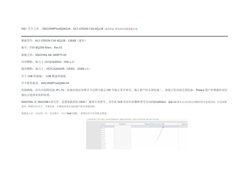
SSD 开卡工具- SM22XMPToolQ0612A - M.2-LITEON CV6-8Q128 -盘的状态错误说坏块数据被污染,
硬盘型号:M.2-LITEON CV6-8Q128 - 128GB(建兴)
板号:CV5-8Q256-Main,Rev.01
板载主控:SM2254G AB ,N04P75.00
闪存颗粒:海力士-H27QFG8PEBLR(64G x 2)
缓存颗粒:海力士 - H5TC2G63GFR(DDR3,256M x 1)
开卡USB转接板:USB硬盘转接板
开卡软件版本:SM22XMPToolQ0612A
短接跳线:首次识别需短接JP1-TG(短接识别后如果开卡过程中提示ISP不能正常开和关,那么量产时去掉短接),如能正常识别无需短接;Pretest量产时根据你实际情况去选择坏块的处理。
SM2254G是SM2258H的马甲,是慧荣提供给OEM厂商的专用型号。
另外此SSD实际闪存颗粒型号为H27QFG8PEBLR,Q0612A版本自动识别出的颗粒型号是错误的,但是参数基本一样就可以开卡,不要在意。
后期如有更合适的量产版本再做更新。
短接进入后。
双击第一行,会出现下一关于flash的图。
表明内存卡还有机会修复。
如果遇到bad block data was been polluted 提示信息,那么修改pretest 为第三个选择项skip
前面的跳线去掉,否则会出现isp running 超时。

磁盘阵列常见日志简介目录1.控制器事件 01.1 严重警告 01.2 一般警告 (1)1.3 通知 (1)2.磁盘 (2)2.1 严重警告 (2)2. 2 一般警告 (3)3.通道 (4)3.1 严重警告 (4)3.2 通知 (6)4.逻辑盘 (6)4.1 严重警告 (6)4.2 通知 (8)5.常见事件 (10)5.1 严重警告 (10)6.周边设备 (11)6.1 严重警告 (12)7.SES 设备 (13)7.1 严重警告 (13)8.常见外围设备 (14)8.1 严重警告 (14)1.控制器事件1.1 严重警告1 .Controller SDRAM ECC <multi-bits/single-bit> Error Detected发生原因:内存Single-bit/Multi-bits Errors处理方法:检查内存是否故障,重新更新FW,如仍有故障请联系供应商解决出现频率:一般2. Controller SDRAM Parity Error Detected发生原因:内存校验错误处理方法:更新FW,更换内存测试,如故障仍未解决,请联系供应商解决。
出现频率:低3. Controller ALERT: Power Supply Unstable or NVRAM Failed发生原因:电源电压输出过低,或者NVRAM内部错误.处理方法:请与供应商联系,如必要可更换新电源出现频率:低4. Controller ALERT: Redundant Controller Failure Detected发生原因:双控制器其中之一发生故障,另一控制器接管处理方法:检查双控制器在硬件、FW及其他设置上是否一致,如确认为硬件故障所致,请联系供应商解决。
出现频率:低5. CHL:_ FATAL ERROR (_)发现原因:其中一个通道发生故障处理方法:请检查连接线路,双控的模式下,让另一控制器将接替故障控制器的工作,并联系供应商解决.6. Controller BBU Absent or Failed!发生原因:BBU(电池)被移走或故障处理方法:检查BBU是否安装正常出现频率:一般7. BBU Failure Detected发生原因:BBU发生故障处理方法:请联系供应商解决.8. Controller PCI Bus Parity Error Detected发生原因:可能由于控制器内部的温度过高造成部件发生故障处理方法:请联系供应商解决.9. Force Controller Write-Through on Triggered Cause发生原因:控制器切换写入方式为Write-Through处理方法:恢复原来的工作状态,如未解决,请联系供应商解决.1.2 一般警告10. Controller BBU Not Fully Charged!发生原因:BBU充电不足,并且不建议将cach的模式由write-throung改为write-back处理方法:如果电池不能满足长时间的电量负荷,请联系供应商更换电池.11. Controller BBU Thermal Shutdown/Enter Sleep-Mode!发生原因:BBU温度过高(>=45),或是充电完成超过7小时造成控制器BBU突然关闭或者休眠.处理方法:检查环境通风是否良好,电池是否安装正确,出现此日志一般不需要进行特别操作12. Memory Not Sufficient to Fully Support Current Config.发生原因:使用的内存与当前的型号或配置不符处理方法:检查内存是否正常,更换内存测试1.3 通知1. CONTROLLER notice: NVRAM Factory Defaults Restored发生原因:Firmware已经恢复到出厂设置处理方法:请按ESC清掉该信息即可.2. Controller Initialization Completed发生原因:控制器初始化完成.处理方法:系统正常启动.3. Controller NOTICE: Redundant Controller Firmware Updated发生原因:冗余控制器的Firmare已经更新处理方法:按ESC清掉该信息即可.4. Memory is Now Sufficient to Fully Support Current Config.发生原因:添加内存或更换新内存已完成处理方法:按ESC清掉该信息即可.5. NVRAM Restore from Disk is Completed发生原因:已从disk保存的配置恢复到当前运行的配置处理方法:按ESC清掉该信息即可.6. NVRAM Restore from File is Completed发生原因:已从先前保存的一个配置文件恢复到当前运行的配置处理方法:按ESC清掉该信息即可.7. NOTICE: Controller BBU Back On-Line!发生原因:之前报错故障的BBU恢复工作处理方法:按ESC清掉该信息即可.8. NOTICE: Controller BBU Fully Charged!发生原因:控制器BBU充电完成处理方法:按ESC清掉该信息即可.9. NOTICE: Controller BBU Present!发生原因:曾丢失BBU,现已恢复.处理方法:按ESC清掉该信息即可.10. NOTICE: Controller FAN On-Line(_RPM)发生原因:之前报错故障的控制器风扇恢复工作处理方法:按ESC清掉该信息即可.2.磁盘2.1 严重警告1. CHL:_ ID:_ SCSI Target ALERT: Unexpected Select Timeout发生原因:硬盘响应超时,硬盘或与主机的连接线被移走均会导致此问题发生处理方法:检查硬盘是否安装到位,连接线是否可靠2. CHL:_ ID:_ SCSI Target ALERT: Gross Phase/Signal Error Detected发生原因:此通道信号异常处理方法:请联系供应商解决3. CHL:_ ID:_ SCSI Target ALERT: Unexpected Disconnect Encountered发生原因:驱动器通道意外中断处理方法:请检查连接线路,如未解决,请联系供应商.4. CHL:_ ID:_ SCSI Drive ALERT: Negotiation Error Detected发生原因:磁盘通道异常处理方法:请联系供应商解决.5. CHL:_ ID:_ SCSI Target ALERT: Timeout Waiting for I/O to Complete发生原因:可能由于硬盘故障或是线路问题造成硬盘I/O读写超时处理方法:请检查连接线路和硬盘,如未解决,联系供应商解决.6. CHL:_ ID:_ SCSI Target ALERT: SCSI Parity/CRC Error Detected发生原因:磁盘通道发生校验错误处理方法:请检查磁盘连接线路和硬盘, 如未解决,联系供应商解决.7. CHL:_ ID:_ SCSI Target ALERT: Data Overrun/Underrun Detected发生原因:此位置硬盘数据溢出错误处理方法:重新插入此硬盘或更换新硬盘测试,重新更新FW,如故障仍未解决请联系供应商.出现频率:极低8. CHL:_ ID:_ SCSI Target ALERT: Invalid Status/Sense Data Received(Sense_key Sense_code)发生原因:磁盘不能接收到客户端的数据处理方法:请检查磁盘连接线路和硬盘.9. CHL:_ ID:_ SCSI Drive ALERT: Drive HW Error (Sense_key Sense_code)发生原因:磁盘驱动器不能获得硬件的错误报表.处理方法:插拔故障磁盘,让热备盘进行数据的重建.10. CHL:_ ID:_ SCSI Drive ALERT: Bad Block Encountered - Block_number(Sense_key Sense_code)发生原因:磁盘不能获得介质的错误报表,控制器请求磁盘重试.处理方法:按ESC清掉该信息即可11. CHL:_ ID:_ SCSI Drive ALERT: CHL:_ ID:_ Clone Failed发生原因:磁盘初始化无响应处理方法:请检查磁盘连接线路和硬盘,如未解决,请联系供应商.12. Slot _ _ Drive ALERT: Bad Block Encountered - * * * * * * * * *发生原因:在一个RAID 1/3/5的阵列中,通过介质扫描或是在数据重建的过程中,可能出现发现坏块的事情,但如果显示是“Bad Block Encountered”,说明这不是当前的事情,已经由控制器将坏块所在的数据通过数据重建已经转移到了其他好的块道上了.处理方法:按ESC以清掉该错误信息即可.13. CHL:_ ID:_ SCSI Drive ALERT: Block Reassignment Failed -Block_number (Sense_key Sense_code)发生原因:磁盘块分配失败,磁盘可能被认为已经发生故障.处理方法:重新插拔故障硬盘,如未解决,请联系供应商更换新硬盘.14. CHL:_ ID:_ SCSI Drive ALERT: Aborted Command (Sense_keySense_code)发生原因:SCSI磁盘失败命令报告处理方法:按ESC已清掉该错误信息.15. CHL:_ ID:_ ALERT: Media Scan Bad Block Unrecoverable-0x0发生原因:介质扫描不能修复该磁盘的坏块.处理方法:更换新硬盘.以防止数据的丢失.2.2 一般警告1. SMART-CH:_ ID:_ Predictable Failure Detected (TEST)发生原因:当开启模拟SMART的功能测试时提示该信息,说明该磁盘能支持此功能.处理方法:按ESC以清掉该信息即可.2. SMART-CH:_ ID:_ Predictable Failure Detected发生原因:SMART提示该磁盘可能会发生故障,这个信息的提示只会在开启了SMART功能之后才会出现.处理方法:为防止数据的丢失,请联系供应商以更换新硬盘.3. SMART-CH:_ ID:_ Predictable Failure Detected-Starting Clone发生原因:SMART发现该位置的磁盘出现故障,并且备用盘已经在尽行数据的重建.处理方法:请联系供应商以更换新硬盘.4. SMART-CH:_ ID:_ Predictable Failure Detected-Clone Failed发生原因:SMART提示此位置的磁盘已经失效,备用盘接替了该磁盘的数据,并自动关掉该磁盘的电力供应.处理方法:请联系供应商以更换新硬盘.5. CHL:_ ID:_ SCSI Drive ALERT: Block Successfully Reassigned –Block_number (Sense_key Sense_code)发生原因:磁盘坏块被重新成功分配.处理方法:按ESC以清掉该信息即可.6. CHL:_ ID:_ SCSI Drive NOTICE: Scan SCSI Drive Successful发生原因:介质扫描新磁盘成功处理方法:按ESC以清掉该信息即可.3.通道3.1 严重警告1.CHL:_ ALERT: Redundant Loop Connection Error Detected on ID:_发生原因:双环连接情况下,其中一个环路故障或断开处理方法:检查连线是否正常,通道有无故障2.CHL:_ Host Channel ALERT: Channel Failure发生原因:主机通道连接失效处理方法:请检查线路连接,光纤连接或是交换机连接,如果仍未解决问题,请联系供应商.3. CHL:_ Drive Channel ALERT: Channel Failure发生原因:磁盘通道失效.处理方法:请检查线路连接,光纤连接或是交换机连接,如果仍未解决问题,请联系供应商.4. CHL:_ ALERT: Fibre Channel Loop Failure Detected发生原因:光纤通道失效处理方法:请检查线路连接,光纤连接或是交换机连接,如果仍未解决问题,请联系供应商.5. CHL:_ ALERT: Redundant loop for Chl:_ Failure Detected发生原因:其中一个冗余的通道已失效处理方法:请检查线路连接,光纤连接或是交换机连接,如果仍未解决问题,请联系供应商.6. CHL:_ ALERT: Redundant Path for Chl:_ ID:_ Expected but Not Found发生原因:预先设置的通道CHL:_冗余环路连接无效.处理方法:请检查线路连接,光纤连接或是交换机连接,如果仍未解决问题,请联系供应商.7. CHL:_ ID:_ ALERT: Redundant Path for Chl:_ ID:_ Failure Detected发生原因:通道CHL:_冗余环路连接失效处理方法:请检查线路连接,光纤连接或是交换机连接,如果仍未解决问题,请联系供应商.8. CHL:_ Host Channel ALERT: Bus Reset Issued发生原因:通道CHL:_总线重置处理方法:请联系供应商解决.9. CHL:_ Drive Channel ALERT: Data Overrun/Underrun Detected发生原因:CHL:_ ID:_此位置硬盘数据溢出错误处理方法:重新插入此硬盘或更换新硬盘测试,重新更新FW,如故障仍未解决请联系供应商出现频率:极低10. CHL:_ FATAL ERROR (_)发生原因:通道发生严重错误处理方法:请联系供应商解决.11. CHL:_ RCC Channel ALERT: Data Overrun/Underrun Detected发生原因:RCC通道发生数据溢出错误处理方法:请联系供应商解决.12. CHL:_ Host Channel ALERT: Parity/CRC Error Detected发生原因:主机通道发生奇偶校验错误处理方法:请联系供应商解决.13. CHL:_ Drive Channel ALERT: Gross Phase/Signal Error Detected发生原因:此通道信号异常处理方法:请联系供应商解决出现频率:低14. CHL:_ Drive Channel ALERT: Timeout Waiting for I/O to Complete发生原因:由于线路问题或是磁盘故障造成磁盘I/O读写超时处理方法:请联系供应商解决.15. CHL:_ Drive Channel ALERT: Unexpected Disconnect Encountered发生原因:磁盘通道意外中断请联系供应商解决.16. CHL:_ Drive Channel ALERT: Unexpected Select Timeout发生原因:CH响应超时,与主机的连接线被移走会导致此问题发生处理方法:检查连接线是否可靠出现频率:低17. CHL:_ RCC Channel ALERT: Gross Phase/Signal Error Detected发生原因:RCC通道信号异常处理方法:重新更新FW会解决此问题,如故障仍未解决请与供应商联系出现频率:一般18. CHL:_ RCC Channel ALERT: Parity/CRC Error Detected发生原因:RCC通道奇偶校验错误.处理方法:重新更新FW会解决此问题,如故障仍未解决请与供应商联系出现频率:一般19. CHL:_ RCC Channel ALERT: Timeout Waiting for I/O to Complete发生原因:RCC通道I/O读写超时,这可能是连接链路的问题,也可能是盘阵背板的故障问题.处理方法:请联系供应商解决20. Message CHL:_ RCC Channel ALERT: Unexpected DisconnectEncountered发生原因:RCC通道意外中断处理方法:请联系供应商解决3.2 通知1. CHL:_ NOTICE: Fibre Channel Loop Connection Restored发生原因:光纤环路通道恢复正常处理方法:按ESC以清掉该信息即可.2. CHL:_ ID:_ NOTICE: Redundant Path for Chl:_ ID:_ Restored发生原因:通道CHL:_冗余环路连接恢复正常处理方法:按ESC以清掉该信息即可.3. CHL:_ SCSI Drive Channel Notification: SCSI Bus Reset Issued发生原因:SCSI磁盘通道CHL:_总线重置处理方法:按ESC以清掉该信息即可.4. CHL:_ Host Channel Notification: SCSI Bus Reset Issued发生原因:主机通道CHL:_总线重置处理方法:按ESC以清掉该信息即可.5. CHL:_ LIP(__) Detected发生原因:光纤环路LIP被重置.处理方法:按ESC以清掉该信息即可.4.逻辑盘4.1 严重警告1. LG: _ ALERT: CHL:_ ID:_ Media Scan Aborted发生原因:介质扫描失败,可能的原因是用户强迫终止或是严重的系统故障.处理方法:重新手动执行介质扫描,如未解决,请联系供应商解决.2. LG:_ Logical Drive ALERT: Logical Drive Block Marked _________发生原因:通过比较和校验,已经确定坏的数据块,此时连接到此坏的数据块的主机将接收到介质错误的信息.处理方法:磁盘阵列自动尝试执行数据的重建.以恢复坏块的数据.3. LG:_ Logical Drive ALERT: Logical Drive Block Recovered ________发生原因:控制器通过比较和重新校验,已恢复逻辑盘坏块的数据.处理方法:按ESC以清掉该信息即可.4. LG:_ Logical Drive ALERT: Logical Drive Block Marked BAD发生原因:控制器通过比较和重新校验,但无法恢复逻辑盘坏块的数据.此时连接到该坏块的主机将收到介质错误的信息.处理方法:请联系供应商解决.5. LG: Logical Drive ALERT: CHL:_ ID:_ Drive Failure发生原因:对应位置的硬盘已失效处理方法:此故障是硬盘连接问题或硬盘本身故障引起的,请检查硬盘是否插紧,并对此硬盘重新扫描或更换硬盘, 如果盘阵已经设置有备用盘,控制器将自动执行数据的重建.出现频率:一般6. LG: Logical Drive ALERT: CHL:_ ID:_ Drive Missing发生原因:对应位置的硬盘丢失处理方法:此故障是硬盘连接问题或硬盘本身故障引起的,请检查硬盘是否插紧,并对此硬盘重新扫描或更换硬盘。

NANDFLASH坏块管理(参考仅供)NANDFLASH坏块管理【Nand Flash中的坏块(Bad Block)】Nand Flash中,一个块中含有1个或多个位是坏的,就称其为坏块。
坏块的稳定性是无法保证的,也就是说,不能保证你写入的数据是对的,或者写入对了,读出来也不一定对的。
而正常的块,肯定是写入读出都是正常的。
坏块有两种:(1)一种是出厂的时候,也就是,你买到的新的,还没用过的Nand Flash,就可以包含了坏块。
此类出厂时就有的坏块,被称作factory (masked)bad block或initial bad/invalid block,在出厂之前,就会做对应的标记,标为坏块。
具体标记的地方是,对于现在常见的页大小为2K的Nand Flash,是块中第一个页的oob起始位置(关于什么是页和oob,下面会有详细解释)的第1个字节(旧的小页面,pagesize是512B甚至256B 的nand flash,坏块标记是第6个字节),如果不是0xFF,就说明是坏块。
相对应的是,所有正常的块,好的块,里面所有数据都是0xFF 的。
(2)第二类叫做在使用过程中产生的,由于使用过程时间长了,在擦块除的时候,出错了,说明此块坏了,也要在程序运行过程中,发现,并且标记成坏块的。
具体标记的位置,和上面一样。
这类块叫做worn-out bad block。
对于坏块的管理,在Linux系统中,叫做坏块管理(BBM,Bad Block Managment),对应的会有一个表去记录好块,坏块的信息,以及坏块是出厂就有的,还是后来使用产生的,这个表叫做坏块表(BBT,Bad Block Table)。
在Linux内核MTD架构下的Nand Flash驱动,和Uboot中Nand Flash驱动中,在加载完驱动之后,如果你没有加入参数主动要求跳过坏块扫描的话,那么都会去主动扫描坏块,建立必要的BBT的,以备后面坏块管理所使用。

H.248协议学习NGN软交换错误码大全2011-10-1516:34在设备上进行信令跟踪步骤如下(可以直接在华为信令跟踪工具上跟踪):rootmduadminenableconfigsw languagediasudbwin enabledbwin print0x9d11dbwin send0x9d11MA5620E(config)#diagnoseMA5620E(diagnose)%%suChallenge:TMCE59ACPlease input password://使用密码生成工具生成动态密码MA5620E(su)%%dbwin enableMA5620E(su)%%dbwin print0x9d11MA5620E(su)%%dbwin send0x9d11完成以上操作后就可以在设备上直接看到信令的交互流程。
信令完成后,要注意关闭dbwin开关,关闭方法如下:MA5620E(su)%%dbwin print0x9d10MA5620E(su)%%dbwin send0x9d10MA5620E(su)%%dbwin disable建议与总结:由于在设备开启dbwin会对业务处理能力造成一定影响,所以在完成信令跟踪后要及时关闭dbwin开关。
一些H.248概念:1、媒体网关(MG):MG将一种网络中的媒体转换成另一种网络所要求的媒体格式。
2、媒体网关控制器(MGC):MGC对MG中与媒体通道连接控制相关的呼叫状态进行控制。
3、终结点(Termination):终结点是MG上的逻辑实体,它发起和/或接收媒体和/或控制流。
终结点用一些属性来描述,如媒体流、modem和承载能力等属性,这些属性组成了一系列描述。
4、关联(Context):关联是一些终结点具有相互联系而形成的结合体。
有一种特殊的关联称为空关联(Null),它包含所有那些与其它终结点没有联系的终结点。
例如,接入网关中所有的空闲线路都被看作空关联中的终结点。
badblocks 命令硬盘是一个损耗设备,当使用一段时间后可能会出现坏道等物理故障。
电脑硬盘出现坏道后,如果不及时更换或进行技术处理,坏道就会越来越多,并会造成频繁死机和数据丢失。
最好的处理方式是更换磁盘,但在临时的情况下,应及时屏蔽坏道部分的扇区,不要触动它们。
badblocks就是一个检查坏道位置的工具。
功能说明:badblocks指令用来检查磁盘,指定磁盘装置和磁盘块数来进行磁盘的坏道检查,以及进行相应的修复。
badblocks是e2fsprogs包的一部分。
扫描硬盘是否有坏区badblocks -b 1024 -c 1 /dev/sda1 -v一、命令参数badblocks使用格式为:引用badblocks [ -svwnf ] [ -b block-size ] [ -c blocks_at_once ] [ -iinput_file ] [ -o output_file ] [ -p num_passes ] [ -t test_pattern ]device [ last-block ] [ start-block ]参数含义是:引用-b blocksize指定磁盘的区块大小,单位为字节,默认值为“block 4K ”(4K/block)-c blocksize每个区块检查的次数,默认是16次-f强制在一个已经挂载的设备上执行读写或非破坏性的写测试操作(我们建议先umount设备,然后再进行坏道检测。
仅当/etc/mtab出现误报设备挂载错误的时候可以使用该选项)-i file跳过已经显示在file文件中的坏道,而不进行检测(可以避免重复检测)-o file把检测结果输出到file文件-p number重复搜寻设备,直到在指定通过次数内都没有找到新的坏块位置,默认次数为0-s在检查时显示进度-t pattern通过按指定的模式读写来检测区块。
你可以指定一个0到ULONG_MAX-1的十进制正值,或使用random(随机)。

摘要近年来,随着技术的进步,NAND Flash型闪存已逐渐褪去其以往高价的形象,在轻巧度、可靠度以及容量上不断地提升,加上其低功耗、掉电非易失等特点,已被广泛应用于各种移动设备及嵌入式存储系统中。
以NAND Flash作为存储介质的固态硬盘(SSD),由于具有普通的磁介质硬盘(HDD)所不能比拟的优点,在近些年来迅速成为存储领域的热点技术。
然而,一个典型的NAND Flash器件是由若干个块(block)组成,而每块又包含若干页(page),其特殊的物理结构使NAND Flash无法像磁介质硬盘一样原地更新数据,因此,需要在文件系统及物理层之间加入闪存转换层(FTL),解决文件系统的逻辑扇区地址与NAND Flash物理页地址的映射问题。
本文提出并实现了一套基于NAND Flash阵列存储系统中FTL的设计算法,包含地址映射、坏块管理,主要完成的工作如下:[1].构建地址映射对于逻辑地址到物理地址的映射,实现了一种基于LOG BLOCK的混合映射机制,可以有效的避免不必要的拷贝与擦除操作,做到实时更新映射表,节约映射时间,且同时减小了映射表占有的空间大小。
[2].坏块管理以数组的形式对系统中的32片NAND Flash的坏块进行管理,对于出厂坏块及使用坏块使用不同的判别方法。
实现了坏块检测及坏块重映射,保证数据不会因坏块的存在造成丢失。
[3].FTL整体测试针对本课题的预期设计结果,进行了相关的可靠性及稳定性测试,并对实验结果进行了分析。
经过测试,实验运行结果实现了预期研究方案中的功能,达到了预期的结果,有效的减小了映射表的大小和页拷贝、块擦除次数,提高了系统性能。
关键词:NAND Flash FTL 地址映射坏块管理AbstractWith the technological advances, NAND Flash memory has gradually changed its image of costliness in recent years. In the area of weight, reliability and capacity, NAND Flash has upgraded continuously, with its characteristics of low power-consumption and non-volatile, NAND Flash has been widely used in a variety of mobile devices and embedded memory systems. The solid-state drive (SSD), which is a storage system based on NAND Flash, completely eliminates the mechanical defects of the hard disk drive (HDD). Therefore, NAND Flash is rapidly becoming a hot area of storage technology recently. However, a typical NAND Flash device is made up of number of blocks, and each block is made up of number of pages, its unique physical structure enable NAND Flash’s updating operation is different from HDD’s, because NAND Flash need a write should be preceded by an erase operation. So, a flash translation layer (FTL) is introduced to solve the mapping problem between the logical address and physical address. In this paper, the design of FTL in NAND Flash array system includes the following:[1].Mapping schemeTo complete the mapping, a LOG BLOCK-based hybrid mapping scheme is proposed. It can effectively avoid the unnecessary copying and erasing operations, and achieve the real-time updating. The scheme is time-saving and space-saving.[2].Bad block managementIn the form of an array to manage bad blocks, there are different methods to identify the initial and runtime bad blocks. The implementation of the bad blocks re-mapping to ensure that data would not be lost due to bad blocks.[3].The overall test for FTLFor the expecting result of the design, a relevant test of the reliability and stability is carried out, and experimental results are analyzed.All of the experimental results showed that the design of FTL in NAND Flash array system was compact and steady, the mapping scheme implemented in the FTL reduced the size of mapping table, the times of page copy and block erase effectively. It provided well compatibility in the system.Key Words:NAND Flash FTL Address Mapping Bad Block Management目录第1章绪论 (1)1.1 课题来源及意义 (1)1.2 课题相关技术背景 (1)1.2.1 固态硬盘简介及其分类 (1)1.2.2 固态硬盘控制器简介 (3)1.2.3 SSD设计的关键问题 (4)1.3 本文的研究内容与组织结构 (4)第2章NAND Flash阵列存储系统的基本原理 (8)2.1 Flash型存储器简介 (8)2.1.1 NAND Flash与NOR Flash (8)2.1.2 SLC NAND Flash与MLC NAND Flash (10)2.1.3 NAND Flash器件的指令 (12)2.1.4 NAND Flash器件的操作特点 (14)2.1.5 NAND Flash器件的相关参数介绍 (15)2.2 NAND Flash阵列存储系统硬件结构 (17)第3章 NAND Flash阵列存储系统中FTL的设计与实现 (19)3.1 两种典型的设计方法 (19)3.1.1 闪存型文件系统 (19)3.1.2采用FTL结构的文件系统 (20)3.2 FTL的多种算法研究 (21)3.3 NAND Flash阵列存储系统中FTL的设计方法 (26)3.3.1 FTL的设计目标 (26)3.3.2 FTL设计流程 (27)3.4 地址映射的实现 (29)3.4.1 NAND Flash阵列混合地址映射的实现 (29)3.4.2 映射表查找及更新方法 (37)3.5坏块管理表的建立方法 (37)3.5.1 坏块管理流程 (37)3.5.2 初始化坏块检测的实现 (39)3.5.3使用中坏块的辨识与检测 (40)3.5.4坏块查找表与重映射原理 (41)3.6冗余字节的信息存储安排 (41)第4章实验结果分析 (43)4.1 系统兼容性分析 (43)4.2突发状况下保证数据安全方法 (43)4.3 实验测试方案及结果 (44)4.3.1 实验测试方案 (44)4.3.2 坏块管理形式 (44)4.3.3地址映射机制的比较 (45)4.3.4 读写测试及分析 (47)总结 (52)参考文献 (54)致谢 (57)第1章绪论1.1 课题来源及意义NAND Flash,一种非易失性存储介质,在没有电流供应的条件下也能够长久地保持数据,其存储特性相当于硬盘。
启动的时候出现一大串:block 2 is badblock 3 is badblock 4 is badblock 5 is badblock 6 is badblock 7 is badblock 8 is badblock 9 is bad...VFS: Mounted root (yaffs filesystem).Freeing init memory: 120KWarning: unable to open an initial console.Failed to execute /linuxrc. Attempting defaults...Kernel panic - not syncing: No init found. Try passing init= option to kernel.或者block 2 is bad没有出现,直接显示VFS: Mounted root (yaffs filesystem).Freeing init memory: 120KWarning: unable to open an initial console.Failed to execute /linuxrc. Attempting defaults...Kernel panic - not syncing: No init found. Try passing init= option to kernel.其实都是MTD没有正确地读取到root, 可以在u-boot 中执行nand bad, 查看bad block 的信息, 如果从0x200000 - 0x1200000 之间有很多bad block说明nand write.yaffs 这个命令还有问题, OOB 的信息没有正确地写入在NANDFLASH, 只写入了data, 而OOB 没有写进去.下面说说如果解决这个问题:在NANDFLASH 的写入过程中, 其中会调用nand_do_write_ops, 在这个函数中,if (unlikely(oob))oob = nand_fill_oob(chip, oob, ops);这两行要注意, 在这两行之前OOB buf一直都是正解的,但这两行之后, OOB 的数据就变成了0xFF了,在靠前的一些block OOB 都是0xFF,但是到了后面OOB的数据就变得杂乱无章了,所以就会出现一大串的bad flash,为什么会变成没有规律,原因还没有找到,将这两行MASK,改为memcpy(chip->oob_poi, oob, ops->ooblen);问题就解决了,或者在nand_write_opts 函数中将oob_ops.mode = MTD_OOB_AUTO;改为oob_ops.mode = MTD_OOB_RAW;问题同样可以解决.。
Flash 1 Gbit (128M x 8)3.3V NAND Flash Memory FEATURESz Voltage Supply: 3.3V (2.7V~3.6V)z Organization- Memory Cell Array: (128M + 4M) x 8bit- Data Register: (2K + 64) x 8bitz Automatic Program and Erase- Page Program: (2K + 64) Byte- Block Erase: (128K + 4K) Bytez Page Read Operation- Page Size: (2K + 64) Byte- Random Read: 25us (Max.)- Serial Access: 25ns (Min.) (3.3V)z Memory Cell: 1bit/Memory Cellz Fast Write Cycle Time- Program time: 300us - typical- Block Erase time: 3ms - typicalz Command/Address/Data Multiplexed I/O Portz Hardware Data Protection- Program/Erase Lockout During Power Transitions z Reliable CMOS Floating Gate Technology- ECC Requirement: - 4bit/512Byte,- Endurance: 100K Program/Erase cycles- Data Retention: 10 yearsz Command Register Operationz Automatic Page 0 Read at Power-Up Option- Boot from NAND support- Automatic Memory Downloadz NOP: 4 cyclesz Cache Program Operation for High Performance Program z Cache Read Operationz Copy-Back Operationz EDO modez OTP Operationz Bad-Block-ProtectORDERING INFORMATIONProduct ID Speed Package Comments F59L1G81MA -25TG2Y25 ns48 pin TSOPI Pb-free F59L1G81MA -25BG2Y 25 ns 63 ball BGA Pb-free F59L1G81MA -25BCG2Y 25 ns 67 ball BGA Pb-freeGENERAL DESCRIPTIONThe device is a 128Mx8bit with spare 4Mx8bit capacity. The device is offered in 3.3V Vcc Power Supply. Its NAND cell provides the most cost-effective solution for the solid state mass storage market. The memory is divided into blocks that can be erased independently so it is possible to preserve valid data while old data is erased.The device contains 1024 blocks, composed by 64 pages consisting in two NAND structures of 32 series connected Flash cells. A program operation allows to write the 2,112-Byte page in typical 300us and an erase operation can be performed in typical 3ms on a 128K-Byte for X8 device block.Data in the page mode can be read out at 25ns cycle time per Byte. The I/O pins serve as the ports for address and command inputs as well as data input/output. The copy back function allows the optimization of defective blocks management: when a page program operation fails the data can be directly programmed in another page inside the same array section without the time consuming serial data insertion phase. The cache program feature allows the data insertion in the cache register while the data register is copied into the Flash array. This pipelined program operation improves the program throughput when long files are written inside the memory. A cache read feature is also implemented. This feature allows to dramatically improving the read throughput when consecutive pages have to be streamed out. This device includes extra feature: Automatic Read at Power Up.PIN CONFIGURATION (TOP VIEW) (TSOPI 48L, 12mm X 20mm Body, 0.5mm Pin Pitch)BALL CONFIGURATION (TOP VIEW) (BGA 63 BALL, 9mm X 11mm Body, 0.8 Ball Pitch)BALL CONFIGURATION (TOP VIEW) (BGA 67 Ball, 6.5mmx8mmx1.0mm Body, 0.8mm Ball Pitch)Note: Connect all V CC and V SS pins of each device to common power supply outputs. Do not leave V CC or V SS disconnected.BLOCK DIAGRAMARRAY ORGANIZATIONArray AddressI/O0 I/O1 I/O2 I/O3 I/O4 I/O5 I/O6 I/O7 Address1st cycle A0 A1 A2 A3 A4 A5 A6 A7 ColumnAddress 2nd cycle A8 A9 A10 A11 L* L* L* L* ColumnAddress 3rd cycle A12 A13 A14 A15 A16 A17 A18 A19 RowAddress4th cycle A20 A21 A22 A23 A24 A25 A26 A27 RowAddressNote:1. ColumnStarting Address of the Register.Address:2. *L must be set to “Low”.3. The device ignores any additional input of address cycles than required.Product IntroductionThe device is a 1Gbit memory organized as 128K rows (pages) by 2,112x8 columns. Spare 64x8 columns are located from column address of 2,048~2,111. A 2,112-byte data register is connected to memory cell arrays accommodating data transfer between the I/O buffers and memory during page read and page program operations. The program and read operations are executed on a page basis, while the erase operation is executed on a block basis. The memory array consists of 1,024 separately erasable 128K-byte blocks. It indicates that the bit-by-bit erase operation is prohibited on the device.The device has addresses multiplexed into 8 I/Os. This scheme dramatically reduces pin counts and allows system upgrades to future densities by maintaining consistency in system board design. Command, address and data are all written through I/O's by bringing WE to low while CE is low. Those are latched on the rising edge of WE. Command Latch Enable (CLE) and Address Latch Enable (ALE) are used to multiplex command and address respectively, via the I/O pins. Some commands require one bus cycle. For example, Reset Command, Status Read Command, etc require just one cycle bus. Some other commands, like page read and block erase and page program, require two cycles: one cycle for setup and the other cycle for execution.In addition to the enhanced architecture and interface, the device incorporates copy-back program feature from one page to another page without need for transporting the data to and from the external buffer memory.Command SetFunction 1st Cycle 2nd Cycle Acceptable Command during BusyRead 00h30h Read for Copy Back 00h 35hRead ID 90h -Reset FFh-OPage Program 80h 10hCopy-Back Program 85h 10hBlock Erase 60h D0hRandom Data Input(1) 85h -Random Data Output(1) 05h E0hRead Status 70h - OCache Program 80h 15hCache Read 31h -Read Start For Last PageCache Read3Fh -Note: Random Data Input / Output can be executed in a page.ABSOLUTE MAXIMUM RATINGSParameter Symbol Rating UnitV CC-0.6 to +4.6VVoltage on any pin relative to V SSV IN-0.6 to +4.6V I/O-0.6 to V CC + 0.3 (< 4.6)Temperature Under Bias T BIAS-40 to +125 ℃Storage Temperature T STG-65 to +150 ℃Short Circuit Current I OS 5 mANote:Permanent device damage may occur if ABSOLUTE MAXIMUM RATINGS are exceeded. Functional operation should be restricted to the conditions as detailed in the operational sections of this data sheet. Exposure to absolute maximum rating conditions for extended periods may affect reliability.RECOMMENDED OPERATING CONDITIONS℃(Voltage reference to GND, T A = 0 to 70)Parameter Symbol Min. Typ. Max. UnitVSupply Voltage V CC 2.7 3.3 3.6VSupply Voltage V SS0 0 0DC AND OPERATION CHARACTERISTICSNote:1. V IL can undershoot to -0.4V and V IH can overshoot to V CC+0.4V for durations of 20ns or less.2. Typical value are measured at V CC =3.3V, T A=25. And not 100% tested.℃VALID BLOCKSymbol Min. Typ. Max. Unit1024Block-N VB 1004Note:1. The device may include initial invalid blocks when first shipped. Additional invalid blocks may develop while being used. Thenumber of valid blocks is presented with both cases of invalid blocks considered. Invalid blocks are defined as blocks that contain one or more bad bits which cause status failure during program and erase operation. Do not erase or program factory-marked bad blocks. Refer to the attached technical notes for appropriate management of initial invalid blocks.2. The 1st block, which is placed on 00h block address, is guaranteed to be a valid block at the time of shipment and is guaranteed tobe a valid block up to 1K program/erase cycles with 4bit/512Byte ECC.AC TEST CONDITION(T A=0 to 70, V℃CC=2.7V~3.6V)Parameter ConditionInput Pulse Levels 0V to V CCInput Rise and Fall Times 5 nsInput and Output Timing Levels V CC /2Output Load* 1 TTL Gate and C L=50pFNote: Refer to Ready/Busy, R/B output’s Busy to Ready time is decided by the pull-up resistor (Rp) tied to the R/B pin.CAPACITANCE(T A=25, V℃CC=3.3V, f=1.0MHz)Item Symbol Test Condition Min. Max. UnitInput / Output Capacitance C I/O V IL = 0V - 8 pFInput Capacitance C IN V IN = 0V - 8 pF Note: Capacitance is periodically sampled and not 100% tested.H L LL H LH L LL H LL L LL L L HNote:1. X can be V IL or V IH.2. WP should be biased to CMOS high or CMOS low for stand-by.Program / Erase Characteristics(T A=0 to 70℃, V CC=2.7V~3.6V)Parameter Symbol Min. Typ. Max. UnitAverage Program Time t PROG - 300 750 us Dummy Busy Time for Cache Program t CBSY - 3 750usNumber of Partial Program Cycles in the Same Page N OP- - 4CycleBlock Erase Time t BERS- 3 10ms Note:1. Typical program time is defined as the time within which more than 50% of the whole pages are programmed at 3.3V V CC and 25℃temperature.2. tPROG is the average program time of all pages. Users should be noted that the program time variation from page topage is possible.3. Max. time of t CBSY depends on timing between internal program completion and data in.Note:1. The transition of the corresponding control pins must occur only once while WE is held low.2. t ADL is the time from the WE rising edge of final address cycle to the WE rising edge of first data cycle.Note:1. If reset command (FFh) is written at Ready state, the device goes into Busy for maximum 5us.NAND Flash Technical NotesMask Out Initial Invalid Block(s)Initial invalid blocks are defined as blocks that contain one or more initial invalid bits whose reliability is not guaranteed by ESMT. The information regarding the initial invalid block(s) is called the initial invalid block information. Devices with initial invalid block(s) have the same quality level as devices with all valid blocks and have the same AC and DC characteristics. An initial invalid block(s) does not affect the performance of valid block(s) because it is isolated from the bit line and the common source line by a select transistor. The system design must be able to mask out the initial invalid block(s) via address mapping.The 1st block, which is placed on 00h block address, is guaranteed to be a valid block up to 1K program/erase cycles with 4bit/512Byte ECC.Identifying Initial Invalid Block(s) and Block Replacement ManagementAll device locations are erased (FFh) except locations where the initial invalid block(s) information is written prior to shipping. The initial invalid block(s) status is defined by the 1st byte in the spare area. ESMT makes sure that either the 1st or 2nd page of every initial invalid block has non-FFh data at the 1st byte column address in the spare area.Do not erase or program factory-marked bad blocks. The host controller must be able to recognize the initial invalid block information and to create a corresponding table to manage block replacement upon erase or program error when additional invalid blocks develop with Flash memory usage.Algorithm for Bad Block ScanningCheck “FFh” at the 1st Byte column addressin the spare area of the 1st and 2nd page inthe block.For (i=0; i<Num_of_LUs; i++){For (j=0; j<Blocks_Per_LU; j++){Defect_Block_Found=False;Read_Page(lu=i, block=j, page=0);If (Data[coloumn=First_Byte_of_Spare_Area]!=FFh) Defect_Block_Found=True;Read_Page(lu=i, block=j, page=1);If (Data[coloumn=First_Byte_of_Spare_Area]!=FFh) Defect_Block_Found=True;If (Defect_Block_Found) Mark_Block_as_Defective(lu=i, block=j);}}Error in Write or Read OperationWithin its lifetime, additional invalid blocks may develop with NAND Flash memory. Refer to the qualification report for the actual data. The following possible failure modes should be considered to implement a highly reliable system. In the case of status read failure after erase or program, block replacement should be done. Because program status fail during a page program does not affect the data of the other pages in the same block, block replacement can be executed with a page-sized buffer by finding an erased empty block and reprogramming the current target data and copying the rest of the replaced block. In case of Read, ECC must be employed. To improve the efficiency of memory space, it is recommended that the read or verification failure due to single bit error be reclaimed by ECC without any block replacement. The additional block failure rate does not include those reclaimed blocks.Failure Mode Detection and Countermeasure sequenceErase Failure Read Status after Erase→ Block ReplacementWriteProgram Failure Read Status after Program→ Block ReplacementRead Up to 4 bits Failure Verify ECC → ECC CorrectionNote: Error Correcting Code→RS Code or BCH Code etc.Example: 4bit correction / 512 ByteProgram Flow ChartErase Flow ChartRead Flow ChartBlock ReplacementAddressing for program operationWithin a block, the pages must be programmed consecutively from the LSB (Least Significant Bit) page of the block to MSB (Most Significant Bit) pages of the block. Random page address programming is prohibited.In this case, the definition of LSB page is the LSB among the pages to be programmed. Therefore, LSB page doesn’t need to be page 0.System Interface Using CE don’t-careFor an easier system interface, CE may be inactive during the data-loading or serial access as shown below. The internal 2,112byte data registers are utilized as separate buffers for this operation and the system design gets more flexible. In addition, for voice or audio applications that use slow cycle time on the order of μ-seconds, de-activating CE during the data-loading and serial access would provide significant savings in power consumption.Program/Read Operation with “CE not-care”Address InformationI/O DATA ADDRESSI/Ox Data In / Out Col. Add1 Col. Add2 Row Add1 Row Add2 I/O0 ~ I/O7 2,112 Byte A0 ~ A7 A8 ~ A11 A12 ~ A19 A20 ~ A27Command Latch CycleAddress Latch CycleInput Data Latch CycleSerial access Cycle after Read (CLE = L, ALE = L, WE= H)Note:1. Dout transition is measured at ±200mV from steady state voltage at I/O with load.2. t RHOH starts to be valid when frequency is lower than 33MHz.Serial access Cycle after Read (EDO Type CLE = L, ALE = L, WE= H)Note:1. Transition is measured at +/-200mV from steady state voltage with load.This parameter is sample and not 100% tested. (t CHZ, t RHZ)2. t RLOH is valid when frequency is higher than 33MHZ.t RHOH starts to be valid when frequency is lower than 33MHZ.Status Read CycleRead Operation (Read One Page)Read Operation (Intercepted by CE)Random Data Output In a PagePage Program OperationPage Program Operation with Random Data InputNote: t ADL is the time from WE rising edge of final address cycle to the WE rising edge of first data cycle.11Copy-Back Operation with Random Data InputCache Program OperationCache Read OperationBlock Erase OperationRead ID OperationID Definition TableID Access command = 90hMaker Code Device Code 3rd Cycle 4th Cycle 5th Cycle C8h D1h 80h 95h 40hDescription1st Byte Maker Code2nd Byte Device Code3rd Byte Internal Chip Number, Cell Type, etc4th Byte Page Size, Block Size, etc5th Byte Plane Number, Plane SizeDescription I/O7 I/O6 I/O5 I/O4 I/O3 I/O2 I/O1 I/O0 1 0 0 2 0 1 4 1 0 Internal Chip Number8 1 1 2 Level Cell 0 0 4 Level Cell 0 1 8 Level Cell 1 0 Cell Type16 Level Cell 1 1 1 0 0 2 0 1 4 1 0 Number ofSimultaneouslyProgrammed Pages 8 1 1 Not Support 0 Interleave Program Between Multiple Chips Support 1 Not Support 0 Cache Program Support 14th ID DataDescription I/O7 I/O6 I/O5 I/O4 I/O3 I/O2 I/O1 I/O0 1KB 0 0 2KB 0 1 4KB 1 0 Page Size(w/o redundant area)8KB 1 1 64KB 0 0 128KB 0 1 256KB 1 0 Block Size(w/o redundant area) 512KB 1 1 8 0 Redundant Area Size (Byte/512Byte) 16 1 x8 0 Organizationx16 1 45ns 0 0 Reserved 0 1 25ns 1 0 Serial Access Time Reserved 1 1DescriptionI/O7I/O6I/O5I/O4I/O3I/O2I/O1I/O04bit/512B 0 0 2bit/512B 0 1 1bit/512B 1 0 ECC LevelReserved1 1 1 0 02 0 1 4 1 0 Plane Number8 1 1 64Mb 0 0 0 128Mb 0 0 1 256Mb 0 1 0 512Mb 0 1 1 1Gb 1 0 0 2Gb 1 0 1 4Gb 1 1 0 Plane Size(w/o redundant area)8Gb 1 1 1 Reserved Reserved 0DEVICE OPERATIONPage ReadUpon initial device power up, the device defaults to Read mode. This operation is also initiated by writing 00h command, four-cycle address, and 30h command. After initial power up, the 00h command can be skipped because it has been latched in the command register. The 2,112Byte of data on a page are transferred to cache registers via data registers within 25us (t R). Host controller can detect the completion of this data transfer by checking the R/B output. Once data in the selected page have been loaded into cache registers, each Byte can be read out in 25ns cycle time by continuously pulsing RE. The repetitive high-to-low transitions of RE clock signal make the device output data starting from the designated column address to the last column address.The device can output data at a random column address instead of sequential column address by using the Random Data Output command. Random Data Output command can be executed multiple times in a page.After power up, device is in read mode so 00h command cycle is not necessary to start a read operation.A page read sequence is illustrated in Figure below, where column address, page address are placed in between commands 00h and 30h. After t R read time, the R/B de-asserts to ready state. Read Status command (70h) can be issued right after 30h. Host controller can toggle RE to access data starting with the designated column address and their successive bytes.Read OperationRandom Data Output In a PageThe device is programmed based on the unit of a page. Addressing of page program operations within a block should be in sequential order. A complete page program cycle consists of a serial data input cycle in which up to 2,112byte of data can be loaded into data register via cache register, followed by a programming period during which the loaded data are programmed into the designated memory cells.The serial data input cycle begins with the Serial Data Input command (80h), followed by a four-cycle address input and then serial data loading. The bytes not to be programmed on the page do not need to be loaded. The column address for the next data can be changed to the address follows Random Data Input command (85h). Random Data Input command may be repeated multiple times in a page. The Page Program Confirm command (10h) starts the programming process. Writing 10h alone without entering data will not initiate the programming process. The internal write engine automatically executes the corresponding algorithm and controls timing for programming and verification, thereby freeing the host controller for other tasks. Once the program process starts, the host controller can detect the completion of a program cycle by monitoring the R/B output or reading the Status bit (I/O6) using the Read Status command. Only Read Status and Reset commands are valid during programming. When the Page Program operation is completed, the host controller can check the Status bit (I/O0) to see if the Page Program operation is successfully done. The command register remains the Read Status mode unless another valid command is written to it.A page program sequence is illustrated in Figure below, where column address, page address, and data input are placed in between 80h and 10h. After t PROG program time, the R/B de-asserts to ready state. Read Status command (70h) can be issued right after 10h.Program & Read Status OperationRandom Data Input In a pageCache Program is an extension of Page Program, which is executed with 2,112 byte data registers, and is available only within a block. Since the device has 1 page of cache memory, serial data input may be executed while data stored in data register are programmed into memory cell.After writing the first set of data up to 2,112 bytes into the selected cache registers, Cache Program command (15h) instead of actual Page Program (10h) is inputted to make cache registers free and to start internal program operation. To transfer data from cache registers to data registers, the device remains in Busy state for a short period of time (t CBSY) and has its cache registers ready for the next data-input while the internal programming gets started with the data loaded into data registers. Read Status command (70h) may be issued to find out when cache registers become ready by polling the Cache-Busy status bit (I/O6). Pass/fail status of only the previous page is available upon the return to Ready state. When the next set of data is inputted with the Cache Program command, t CBSY is affected by the progress of pending internal programming. The programming of the cache registers is initiated only when the pending program cycle is finished and the data registers are available for the transfer of data from cache registers. The status bit (I/O5) for internal Ready/Busy may be polled to identity the completion of internal programming. If the system monitors the progress of programming only with R/B, the last page of the target programming sequence must be programmed with actual Page Program command (10h).Cache Program (available only within a block)Note:1. Since programming the last page does not employ caching, the program time has to be that of Page Program. However, if theprevious program cycle with the cache data has not finished, the actual program cycle of the last page is initiated only after completion of the previous cycle, which can be expressed as the following formula.2. t PROG = Program time for the last page + Program time for the (last-1)th page – (Program command cycle time + Last page dataloading time)Copy-Back ProgramCopy-Back Program is designed to efficiently copy data stored in memory cells without time-consuming data reloading when there is no bit error detected in the stored data. The benefit is particularly obvious when a portion of a block is updated and the rest of the block needs to be copied to a newly assigned empty block. Copy-Back operation is a sequential execution of Read for Copy-Back and of Copy-Back Program with Destination address. A Read for Copy-Back operation with “35h” command and the Source address moves the whole 2,112byte data into the internal buffer. The host controller can detect bit errors by sequentially reading the data output. Copy-Back Program is initiated by issuing Page-Copy Data-Input command (85h) with Destination address. If data modification is necessary to correct bit errors and to avoid error propagation, data can be reloaded after the Destination address. Data modification can be repeated multiple times as shown in Figure below. Actual programming operation begins when Program Confirm command (10h) is issued. Once the program process starts, the Read Status command (70h) may be entered to read the status register. The host controller can detect the completion of a program cycle by monitoring the R/B output, or the Status bit (I/O6) of the Status Register. When the Copy-Back Program is complete, the Status Bit (I/O0) may be checked. The command register remains Read Status mode until another valid command is written to it.Page Copy-Back Program OperationPage Copy-Back Program Operation with Random Data InputBlock EraseThe block-based Erase operation is initiated by an Erase Setup command (60h), followed by a two-cycle row address, in which only Plane address and Block address are valid while Page address is ignored. The Erase Confirm command (D0h) following the row address starts the internal erasing process. The two-step command sequence is designed to prevent memory content from being inadvertently changed by external noise.At the rising edge of WE after the Erase Confirm command input, the internal control logic handles erase and erase-verify. When the erase operation is completed, the host controller can check Status bit (I/O0) to see if the erase operation is successfully done. Figure below illustrates a block erase sequence, and the address input (the first page address of the selected block) is placed in between commands 60h and D0h. After t BERS erase time, the R/B de-asserts to ready state. Read Status command (70h) can be issued right after D0h to check the execution status of erase operation.Block Erase OperationRead StatusA status register on the device is used to check whether program or erase operation is completed and whether the operation is completed successfully. After writing 70h command to the command register, a read cycle outputs the content of the status register to I/O pins on the falling edge of CE or RE, whichever occurs last. These two commands allow the system to poll the progress of eachdevice in multiple memory connections even when R/B pins are common-wired. RE or CE does not need to toggle for status change.The command register remains in Read Status mode unless other commands are issued to it. Therefore, if the status register is read during a random read cycle, a read command (00h) is needed to start read cycles.Status Register Definition for 70h CommandI/O Page Program Block EraseCacheProgramRead Cache Read DefinitionI/O0 Pass / Fail Pass / Fail Pass / Fail(N) NA NA Pass: ”0” Fail: ”1” I/O1 NA NA Pass / Fail(N-1)NA NA Don’t caredI/O2NA(Pass / Fail, OTP)NA NA NA NADon’tcaredI/O3 NA NA NA NA NADon’tcared I/O4 NA NA NA NA NADon’tcaredI/O5 NA NA TrueReady / Busy NATrueReady / BusyBusy: ”0”Ready: ”1”I/O6 Ready / Busy Ready / Busy Ready / Busy Ready / Busy Ready / Busy Busy: ”0” Ready: ”1”I/O7 WriteProtect Write Protect Write Protect Write Protect Write Protect Protected: ”0” Not Protected: ”1”Note:1. I/Os defined NA are recommended to be masked out when Read Status is being executed.2. N: current page, N-1: previous page.Read IDThe device contains a product identification mode, initiated by writing 90h to the command register, followed by an address input of 00h. Four read cycles sequentially output the manufacturer code (C8h), and the device code and 3rd, 4th and 5th cycle ID respectively. The command register remains in Read ID mode until further commands are issued to it.Read ID OperationID Definition TableID Access command = 90hMaker Code Device Code 3rd Cycle 4th Cycle 5th CycleC8h D1h 80h 95h 40hResetThe device offers a reset feature, executed by writing FFh to the command register. When the device is in busy state during random read, program or erase mode, the reset operation will abort these operations. The contents of memory cells being altered are no longer valid, as the data will be partially programmed or erased. The command register is cleared to wait for the next command, and the Status Register is cleared to value C0h when WP is high. If the device is already in reset state a new reset command will be accepted by the command register. The R/B pin changes to low for t RST after the Reset command is written. Refer to Figure below.Device StatusAfter Power-up After ResetOperation mode 00h Command is latched Waiting for next commandCache ReadCache Read is an extension of Page Read, and is available only within a block. The normal Page Read command (00h-30h) is always issued before invoking Cache Read. After issuing the Cache Read command (31h), read data of the designated page (page N) are transferred from data registers to cache registers in a short time period of t DCBSYR, and then data of the next page (page N+1) is transferred to data registers while the data in the cache registers are being read out. Host controller can retrieve continuous data and achieve fast read performance by iterating Cache Read operation. The Read Start for Last Page Cache Read command (3Fh) is used to complete data transfer from memory cells to data registers.Read Operation with Cache Read。
Bad-Block Scheme QuestionnaireThis questionnaire must be filled out entirely to assist SG in meeting your NAND needs. Please provide all of the required information. Please attach any documents such as specifications and example source code to this document.1.What is the name of your bad-block scheme and how does it handle bad blocks?PONY : We use the simply way to handle bad-block maintenance –“looking for next available good block” , in other words , if IC-programmer found bad-block , it just search NEXT good block to replace bad one.2.Do you use the spare area? (The last 16 bytes of each page, also referred to as “redundant”area)PONY : Yes , We use spare area for sector info + ECC +bad block flag .3.If you use the spare area, will the data be contained in your data file, or does programmerneed to calculate the values?We just release data file with spare area to our factory , programmer vendor does not need to calculate that .4.If the spare area information is to be calculated by SG, please provide the structure of thespare area below:N/A5.If you are using ECC calculations, please provide your ECC algorithm code at the end of thisdocument or as an e-mail attachment.PONY : We’ll provide ROM image in 2048+64 byte per page format (full page size) for current project. SG does not need to calculate ECC.Actually , SG shall parse the “flash information” to know what is full page size6.Will you be using a file system? If so, please describe the file system details.PONY : SG vendor don’t need to take care file system part , the Data file we release to factory side don’t include the file system7.Are there any portions of your image file that must go at fixed locations in the device,regardless of whether any bad blocks are encountered prior to that location? If so, pleasedescribe. Also, if a bad block is found at that location, should the device fail?PONY : All partitions beginning will be located on start address of partition , that’s all.**Important ** : If too many block blocks led to data is crossover next partition , please show the error message !!!SG vendor shall parse the partition information to know the end of each partition8.Are there any special structures that need to be programmed in the device that need to becalculated by SG? Examples of these would be any mapping tables, partition information, etc.If so, please provide the structure in detail at the end of this document. Specify Big Endian or Little Endian format.PONY : Yes , beginning of the data file is partition information (patition numbers, current patition number ,start address ,end address and length ) and actual size in every partition . DataI/O vendor shall parse this table to program flash. Detailed spec of this header area is as below.Structure of headerThe header include two portions: (1) Flash information and (2) partition information(1)Flash information :(I) SG vendor (IC programmer vendor) can use this information to support variable NANDflash dynamically(II) typedef struct {char name[32] ; //flash IDuint32 page_size ; //every page size – unit bytesuint32 full_page_size ; //every full page size – unit bytesuint32 block_size; //every block size – unit pageuint32 device_size; //device size – unit block}flash_infoPs : full page size = page size + bad block flag + spare data + checksum(2) Partition information(I)Vendor parse this information to know where is every partition beginning , and actual size into every partitionuint32 partition numbers; // how many partitions in the image(II)The format of “Flash_partition_entry” isTypedef struct {uint32 current_patition_number; // which partitionuint32 partition_start_address; // a full page unit.uint32 partition_end_address; // a full page unituint32 partition_real_length; // a full page unit} flash_partition_entry(3) Graphical representation of image(4) Graphical representation of NAND after programming (example)(just list from MIBIB to NV_Backup)OEMSBL 1OEMSBL 2PIDAMSSNV BackupMIBIBQCSBLActual DataReserved size (0xFF)9.Please list any dynamic fields that need to be programmed to the device that must be given toyou as a parameter at job creation time. An example would be if you need to program a code version number into the device that is not contained in the data file, or if a particular region of the device needs to be movable by you, etc. If any of the fields are more than one byte,specify Big Endian or Little Endian format.PONY : SG vendor just program data file into flash accordingly10.Please provide a graphical representation of how your bad-block scheme would handle adevice that had a bad block at block 3, 7, and 10. Please use whichever graphical program you need to depict what would happen, just be sure to provide a clear representation. PONY : please check the below table11.Is there anything else that needs to be programmed into your device that will need to becomputed or handled in a special way by SG? If so, please provide a complete description and any applicable code to assist us in meeting your needs.PONY : no so far12.What is the contact information for the appropriate person that knows the details of thisscheme?-Name: Pony Ma (System Software Dept.)-Title: Senior Engineer-phone # :-e-mail address :-Your Semiconductor FAE Name:-Your Semiconductor FAE Phone #:13.If the block at the beginning of any partition is bad, shall we reject the device whenprogramming?PONY : NO , its possible case that the beginning of any partition is bad , just think it as normal bad block14.In the following figure, can I understand that the partition structure begin from address0? Then the Partition start address for MIBIB cannot be 0. Or, shall we read partitioninformation from a separate file?PONY : Actually , the "partition structure" is just information to describe the following partitions , you can’t flash "partition information" into flash In other words , MIBIB is first one partition 15.What is the partition information table end mark?PONY : we gave you the structure of partition information , so you shall know the end of partition information16.There is “Flash Information” structure included in the BBM questionnaire. Is it just for ourreference but not a part of the image file?PONY : The flash information like partition informati on , it don’t be included into MIBIB so it also cant be burn to flash. SG vendor can know flash information like page size , full page size , device size and so on , therefore your program can support various flash depend on "flash information"。