测绘三脚架的复位装置说明书
- 格式:docx
- 大小:247.00 KB
- 文档页数:3
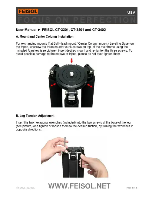
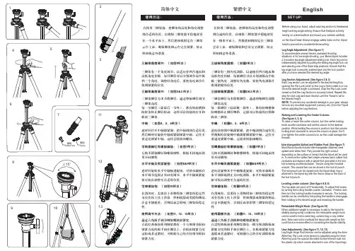
User Manual ► FEISOL CT-3301, CT-3401 and CT-3402A. Mount and Center Column InstallationFor exchanging mounts (flat Ball-Head mount / Center Column mount / Leveling Base) on the tripod, unscrew the three counter-sunk screws on top of the mainframe using the included Alan key (see picture), insert desired mount and re-tighten the three screws. To avoid possible damage to the screws or tripod, please do not over-tighten them.B. Leg Tension AdjustmentInsert the two hexagonal wrenches (included) into the two screws at the base of the leg (see picture) and tighten or loosen them to the desired friction, by turning the wrenches in opposite directions.C. Leg ExtensionIn order to extend a leg section, turn the twist-lock approximately one half turn in counterclockwise direction. Note: If the twistlock is turned too far, the leg section may fall out and compression rings may become lost or damaged.To firmly lock a leg section into place, turn the twist-lock approximately one half turn in clockwise direction. Please do not over-tighten.D. Weight Hook InstallationTo increase tripod stability during windy conditions a Weight Hook is included, allowing for heavier objects (backpack, weight bags) to be attached to the tripod. The hook can be screwed onto the bottom plate of the pre-installed Center Column (see picture).E. Ball-Head (optional) InstallationWhen using the flat mounting plate (pre-installed on models CT-3372 and CT-3472), screw the Ball-Head into the mounting screw by turning the Ball-head clockwise until it fits snugly. Please do not over-tighten.When using a Center Column, making sure that the Center Column is securely locked, screw the Ball-Head onto the mounting screw by turning the Ball-Head clockwise (see picture). Please do not over-tighten.F. Spike (optional) InstallationRemove the rubber caps on the end of the legs by twisting and working them forward – they fit snugly in order to prevent them from coming off accidentally. After they are removed, a thread is exposed at the tip of the leg, into which a long or short spike can be screwed (for use on scratch- sensitive surfaces, remove spike and replace rubber cap).Please note that damage to your tripod’s Carbon Tubes or Aluminum parts can occur when they dropped, squeezed, overloaded, or forced downward (eg. into sand dunes or snowbanks). Please exercise care to avoid such conditions.。

全站仪使用指导书1. 全站仪安装到三角架上,一只手紧握全站仪上方提手,用另一只手旋紧三角架锁母与全站仪联接,在完成旋紧动作前手不要离开全站仪提手。
三角架必需带安全装置。
2. 全站仪开关机:按住全站仪显示屏开关上方一个键即可开机,同时按开关上下两个键即关机。
3. 手操器开关:按手操器开关键即可完成开,当短时间不用时按一下即进入待机状态;按住开关键2秒钟左右会出现一个对画框:当长时间不用时,按Power off 键即可实现长时间关机。
当系统出现故障时按Reset 键即实现系统重新启动。
当进行系统重新启动时,会出现:如下对画框:按OK 键进行系统重装(一般情况下,不要进行系统重装!),按Cancel 键即退出重装。
4. 单击Start 键出现3DimObserverV4或在Promgrams 文件夹中找到3DimObserverV4程序,单击后进入操作程序。
5. 选择English(en)进行语言选择,点键进入操作界面。
按single sheet 栏,出现如下菜单:如果是有靶标则选择第一栏,如无靶标则选择第二栏。
其它用的较少。
6.坐标系统建立:点击测出第一点,点击测出第二点;点击下方键选则中的下拉菜单中的键进入新界面:点击进入以下界面。
点击选择点1和点2做为X轴上的两点,点进入点击选择点1做为坐标圆点,点入以下界面。
7.自动寻找已经测量的点:选中已测量的点的名称,点击键,点下拉菜单中的,再点下接菜单中的全站仪将自动旋转找到该测量点。
8.移位测量:将全站仪移位,重新调整水平;点击键,点下拉菜单中的进入以下界面;左边一栏为移动前所测点,右边栏为移位后所测点。
点左边的点然后点击OK 回到原先界面,全站仪移位完成。
移位检测:选择原先测过的点,点击,再点下接菜单中的全站仪将自动旋转找到该测量点,重新测量并检查该坐标数据,与移位前测量数量相同,证明全站仪移位后各点坐标数据不变,证明移位成功;可以找正其它点。
9.根据已知坐标数据,使用全站仪自动找出所需坐标点的实际位置。

Radian TRIPOD BALL HEAD23Attaching/Removing the Radian ™ Ball HeadTo mount the ball head to the tripod:1. Lift the Quick-Release Locking Latch on the tripod.2. Press and hold the Platform Release Button andfully seat ball head into the tripod. Once seated, the ball head can be oriented in any direction. 3. Rotate the Quick-Release Locking Latch down tothe locked position.4. To remove the ball head, follow these steps inreverse order.NOTE: If needed, the locking latch can be repositioned by shifting the latch to the left and rotating the latch up/down to reposition.Quick-Release PlateQuick-ReleaseBubble LevelDrag Tension KnobPress the Quick-Release Button on the tripod to seat the ball head.Quick-Release Locking LatchBase Panning KnobCounterweight HookTo help stabilize the tripod in windy conditions, hang a weight from the Counterweight Hook.Radian TRIPOD BALL HEAD45Tilt ActionThe ball head’s tilt can be adjusted by unlocking the ball head. This allows you to position your optic at the desired angle. For extreme angle, or full vertical orientation, rotate the head into one of the two cutaways.• To unlock the ball head, rotate the Ball Locking Knob counter-clockwise until the head moves freely. Adjust to your desired position and lock the ball head.• To lock the ball head, rotate the Ball Locking Knob clockwise until you feel tension on the knob.Panning ActionThe Radian ™ Ball Head can be adjusted to allow you to pan across a scene without adjusting the ball head’s angle. This is particularly helpful while glassing wildlife moving across a field, maintaining a flexible shooting position for your mounted rifle.To use the Panning Base Knob:• To unlock the panning base, twist the Panning Base Knob counter-clockwise.• To lock the panning base, twist the Panning Base Knob clockwise. You may also adjust the drag of the panning base by tightening the Panning Base Knob, but not locking it down completely. This will allow you to have more control for smoother panning across a scene.Adjusting Drag TensionThe drag tension can be adjusted on the Radian ™ Ball Head for when the head is in the unlocked position, allowing you to pan and tilt the ball head. This is helpful when viewing fast-paced action scenes. To adjust the drag tension, unlock the ball head by rotating the Ball Locking Knobcounter-clockwise. Turn the Drag Tension Knob clockwise to increase the drag tension, or counter-clockwise to decrease the drag tension.NOTE: Once the drag tension is set, it will stay at this tension no matter how much the Ball Locking Knob is loosened.Rotate the Ball Locking Knob to adjust position or lock in place.Adjust the Drag Tension Knob.Rotate the Panning Base Knob to pan or lock in place.Radian TRIPOD BALL HEAD67Attaching Optics to Ball HeadThe Radian ™ Ball Head uses Arca-Swiss style quick-release plates. To mount your optic to the tripod:1. Twist the Quick-Release Locking Knob counter-clockwise to remove the Quick-Release Plate.2. Attach the plate to your optic. Be sure to tighten the Mount Bolt from the bottom side of theplate and flip the D-ring so it lies flat.3. Place the Quick-Release Plate back into the tripod head and turn the Quick-Release LockingKnob clockwise to securely lock the plate in the head. NOTE: To mount binoculars to the tripod, a binocular adapter is required. Purchase Vortex ® binocular adapters from your local dealers.NOTE: Some optics are designed to be Arca-Swiss compatible and can be mounted to the tripod head without the need for plates.TIP: Purchase additional quick-release plates for your optics so it is easy for you to switch equipment.Quick-Release Plate and Mount BoltQuick-Release Locking KnobVIP WARRANTYOUR UNCONDITIONAL PROMISE TO YOU.We promise to repair or replace the product. Absolutely free.Unlimited UnconditionalLifetime Warranty************************•800-426-0048Note: The VIP Warranty does not cover loss, theft, deliberate damage, or cosmetic damagenot affecting product performance.For additional information, and the most up-to-dateproduct manuals, visit 。
简体中文在使用三脚架前,把脚架的高度和角度调整到合适的位置,以确保三脚架能平稳地放置在一个水平面上,然后把相机固定在三脚架云台上面,确保脚架和云台完全锁紧,防止照相机意外滑落。
三脚架有三个角度调节,以适应在凹凸地面和高低角度拍摄。
每只脚管可以分别调节高中低档三个角度,调整好角度后,要把角度调节片推到锁紧的位置。
三脚架脚管为多节数脚管,通过伸缩脚管调节三脚架高度。
每一节脚管(除最后一节外),都有防转槽和防转条防止脚管转动。
这样可以快捷的打开和收放三脚架。
逆时针拧开中轴锁紧圈,把中轴调到合适位置,然后顺时针旋转中轴锁紧圈锁紧中轴,记住不要过度锁紧中轴,这样会毁损坏螺纹。
互换不锈钢脚钉和橡胶脚垫。
根据不同地面使用不同脚垫。
逆时针旋转水平中轴缩进旋钮,可使承载板在水平调节范围正负15度调节。
水平中轴锁紧旋钮可拔出调整至合适的位置。
在刮风时,需要挂上重物增加三脚架的稳定性可在挂钩上挂上沙袋、照相机袋或类似的物品。
注意不能超重,否则反而会影响三脚架的稳定性。
百诺经典板扣系列脚架都有一个方便调节扳扣锁紧力度的扳手扣在脚管上,在扳扣锁紧力度过松或者过紧时,可根据自己的喜好调节扳扣锁紧力度。
通过六角扳手调节脚架螺丝松紧度。
三脚架角度调节:(如图1所示)三脚架高度调节:(如图2&3 所示)中轴:(如图4、5、6所示)水平中轴及锁紧旋钮:(如图8&9所示) 使用调节方法:(如图11、12、13所示)可转换脚钉和橡胶脚垫:(如图7所示)可伸缩挂钩:(如图10所示)English繁体中文Before using your tripod, adjust each leg section to thedesired height and leg angle setting. Ensure that thetripod is firmly resting on a level surface and mount your camera carefully on the tripod head. Always engage safety locks on the tripod head to prevent any accidental dismounting.Leg Angle Adjustment: (See figure 1)To accommodate uneven terrain, awkward shootingsituations or for low angle shooting, your Benro tripod includes a 3-position leg angle adjustment sliding lock. Each leg can be independently adjusted by pulling the sliding leg angle lock out and selecting one of the three step positions. Ensure that the leg angle lock is securely pushed back into the lock position after you have selected the desired leg angle.Leg Section Adjustment: (See figure 2 & 3)Each Leg section can be adjusted to the desired length by opening the Flip Lock Lever so the Leg is free to slide in or out. Once the desired length is achieved, snap the Flip Lock Lever closed so that the Leg Section is securely locked. Repeat this step for each Leg and each Section until the Tripod is set to the desired height.NOTE: To prevent any accidental damage to your gear, always remove any mounted equipment (camera, etc.) from the Tripod before adjusting the Leg Sections.Raising and Lowering the Center Column: (See figure 4, 5, 6)To raise or lower the center column, turn the center locking knob counter-clockwise and set the column to the desired position. While holding the column in position, turn the column locking knob clockwise to secure the column in place. Don't over tighten the center column lock, as this could damage the threads.Interchangeable Spiked and Rubber Feet: (See figure 7)Most Benro tripods include interchangeable stainless steel spiked and rubber feet. They provide the right contactdepending on the surface or terrain that the tripod will be used in. To remove the rubber feet simple unscrew each rubber foot clockwise and replace with a spiked foot (provided in the tool kit) screwing counterclockwise. Secure using the included wrench. The unused feet can be stored in the tool kit pouch. The tool pouch can be clipped onto the tripod strap ring or attached to the tripod leg with the Velcro strap on the back of the tool kit pouch.Leveling center column: (See figure 8 & 9)The top plate can pivot ±15°horizontally. To adjust first loosen by turning the locking handle counter clockwise. Position and then turn the locking handle clockwise to secure. The locking handle can be oriented by first pulling the handle to disengage, then rotating to the desired angle and reseating the handle.Retractable Weight Hook: (See figure 10)When additional weight is necessary to add to the tripod for stability during windy conditions, the retractable weight hook can be used to hold a sand bag, camera bag or any similar item. Take care not to overload the tripod with weight as this could have a reverse effect on increasing the tripods er Adjustments: (See figure 11, 12, 13)Leg Angle Hinge Pivot tension can be adjusted using the 4mm Allen Key. Flip Lock Lever tension is adjusted using the 3mm Allen Key plus the special Six-sided Socket Wrench built into the plastic clip which comes attached to one of the tripod legs.在使用三脚架前,把脚架的高度和角度调整到合适的位置,以确保三脚架能平稳地放置在一个水平面上,然后把相机固定在三脚架云台上面,确保脚架和云台完全锁紧,防止照相机意外滑落。
目录C O N T E N T SPEDESTAL升降台Studio Ped 1-902 Studio Ped 2-752 Vario Ped 1-903 Vario Ped 2-753 Combi Pedestal4 C II Pedestal5 C I Pedestal5OB 20006 EFP 2 CF CF 1507 EFP 2D DA 1508 Hot Pod CF Monopod9 Speed Lock CF10 ENG 2 CF11 CF 10012 ENG 2D DA 10013 ENG 75/2D DA 75 L14 TRIPOD三角架FLUID HEAD 液压云台Video 90 FB Video 60 plus16Video 75 Plus Studio17 Video 75 Plus EFP17 Video 25 plus18 Video 25 plus FB18 Video 20 plus19 Video 20 Sensor19 Video 18 plus20 Video 18 Sensor20 Video 15 Plus21 DV 12 TB22 DV 822 DV 4 II DV 2 II DV 623滑轮车及延伸器24适配及转换器25托板26液压云台手柄26套筒及软包27摄像机配件摄像机承托设备套装适合转播车/工作室摄像机28适合EFP重型摄像机28适合ENG新闻摄像机/便携摄影机29适合数字/专业摄像机/经济装系统30配装指南32德国萨拿三角架Sachtler 萨拿——世界顶级摄像机承托设备 40年前,摄像师Wendelin Sachtler非常不满意他的摄影器材,他决定为自己和同事研制出一种更好的产品。
今天,您在全世界都能看到我们的厂标,这就是萨拿以他的名字命名的高质量、耐用的产品。
在电影和电视专业三角架领域,萨拿成为国际公认的先驱。
萨拿将一如既往的满足您在演播室新技术方面最高标准要求。
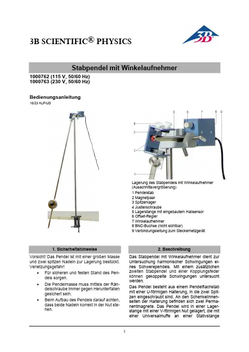
3B SCIENTIFIC ® PHYSICSStabpendel mit Winkelaufnehmer1000762 (115 V, 50/60 Hz) 1000763 (230 V, 50/60 Hz)Bedienungsanleitung10/23 ALF/UDLagerung des Stabpendels mit Winkelaufnehmer (Ausschnittsvergrößerung) 1 Pendelstab 2 Magnetpaar 3 Spitzenlager 4 Justierschraube5 Lagerstange mit eingebautem Hallsensor6 Offset-Regler7 Winkelaufnehmer8 BNC-Buchse (nicht sichtbar)9 Verbindungsleitung zum Steckernetzgerät1. SicherheitshinweiseVorsicht! Das Pendel ist mit einer großen Masse und zwei spitzen Nadeln zur Lagerung bestückt. Verletzungsgefahr!Für sicheren und festen Stand des Pen-dels sorgen.Die Pendelmasse muss mittels der Rän-delschraube immer gegen Herunterfallen gesichert sein.Beim Aufbau des Pendels darauf achten, dass beide Nadeln korrekt in der Nut ste-hen.2. BeschreibungDas Stabpendel mit Winkelaufnehmer dient zur Untersuchung harmonischer Schwingungen ei-nes Schwerependels. Mit einem zusätzlichen z weiten Stabpendel und einer Kopplungsfeder können gekoppelte Schwingungen untersucht werden.Das Pendel besteht aus einem Pendelflachstab mit einer U-förmigen Halterung, in die zwei Spit-zen eingeschraubt sind. An den Schenkelinnen-seiten der Halterung befinden sich zwei Perma-nentmagnete. Das Pendel wird ineinerLager-stange mit einer V-förmigen Nut gelagert, die mit einer Universalmuffe an einer Stativstangebefestigt wird. Die beiden Auflagepunkte für die Spitzenlagerung des Pendels sind durch Ring-marken gekennzeichnet. Zwischen diesen Mar-kierungen befindet sich, eingebaut in der Lager-stange, ein Hallsensor. Er ist so ausgerichtet, dass die Feldlinien in der Pendelruhelage in der Ebene des Chips verlaufen und keine Hallspan-nung bewirken. An die Lagerstange ange-schraubt ist die Elektronikbaugruppe des Win-kelaufnehmers. Der Winkelaufnehmer wandelt den Auslenkwinkel des Pendels in ein proportio-nales elektrisches Signal. Wird das Pendel um den Winkel aus der vertikalen Lage ausge-lenkt, tritt eine horizontale Feldkomponente auf, die je nach Richtung der Auslenkung eine posi-tive oder negative Ausgangsspannung bewirkt. Als Masse beim Schwerependel dient die schei-benförmige Pendelmasse.Die Spannungsversorgung erfolgt über ein im Lieferumfang enthaltenes 12 V AC Steckernetz-gerät.Das Stabpendel 1000762 ist für eine Netzspan-nung von 115 V (±10 %) ausgelegt, 1000763 für 230 V (±10 %).Hinweis: Der Winkelaufnehmer ist auf das Mag-netpaar der Spitzenlagerung abgestimmt, so dass in Ruhestellung des Pendels die Ausgangsspan-nung an der BNC-Buchse etwa Null ist. Eine Fein-abstimmung erfolgt mit dem Offsetregler. Die Zu-ordnung von Spitzenlager und Winkelaufnehmer ist durch eine Zahl auf den Gehäusen gekenn-zeichnet. Bei Verwendung von Komponenten mit unterschiedlicher Zahl kann, bedingt durch Exemplarstreuung der Magnete, eine höhere Off-setspannung auftreten.3. Lieferumfang1 Pendelstab mit U-förmiger Halterung und Spit-zenlager1 Pendelmasse1 Lagerstange mit V-förmiger Nut und ange-schraubtem Winkelaufnehmer1 Steckernetzgerät 12 V AC4. Technische DatenBetriebsspannung: 12 V AC Ausgangsspannung: ±5 V Ausgangswiderstand: 500 Ohm Maximale Pendellänge: 1 m Pendelmasse: 1 kgMasse Winkelaufnehmer: ca. 0,3 kg Lagerstange: 10 mm Ø5. BedienungZum Aufbau des Stabpendels und zur Durchfüh-rung der Experimente sind folgende Geräte zu-sätzlich erforderlich:Zum Aufbau:1 Tischklemme 1002832 1 Stativstange, 1000 mm 1002936 1 Universalmuffe 1002830 Zur Messwerterfassung:1 Computer1 PC-Oszilloskop 2x25 MHz 1020857 1 HF-Kabel, 1 m 1002746 oder1 Spannungssensor 10 V 1021682 1 Adapter BNC-Stecker / 4-mm-Buchsen1002750 1 Datenlogger1 SoftwareWeitere Informationen zum digitalen Messen sind auf der Webseite des Produkts im 3B Webshop zu finden.5.1 Aufbau des StabpendelsZum Aufbau des Stabpendels Stativstange senkrecht mittels der Tischklemme am Ar-beittisch befestigen.Lagerstange mittels der Universalmuffe in ausreichender Höhe an der Stativstange an-bringen.Spitzenlager des Pendels in die vorgesehene Position (Ringmarken) einsetzen.Befindet sich die Lagerstange nicht in hori-zontaler Richtung, Pendel mittels der Justier-schrauben lotrecht justieren.Masse auf den Pendelstab schieben, ge-wünschte effektive Pendellänge L einstellen und Masse mit der Rändelschraube fixieren. Winkelaufnehmer über Steckernetzgerät mit dem Netz verbinden und über die BNC-Buchse und das HF-Kabel an das Oszil-loskop oder mit Hilfe von Adapter und Span-nungssensor an den Datenlogger anschlie-ßen.5.2 Einstellung des OffsetsOszilloskop bzw. Datenlogger einschalten. Tritt in Ruhelage des Pendels eine von Null abweichende Ausgangsspannung auf, diese mit dem Offset-Regler kompensieren.3B Scientific GmbH Ludwig-Erhard-Straße 20 20459 Hamburg Deutschland Technische Änderungen vorbehaltenFig. 1 Kalibrierung der Ausgangsspannung, A: Maßstab5.3 Kalibrierung der Ausgangsspannung Zur quantitativen Auswertung von Experimenten ist es erforderlich, den genauen Zusammenhang von Ausgangsspannung und Auslenkwinkel zu kennen.Mit Hilfe eines Maßstabs Auslenkwinkel geo-metrisch bestimmen (siehe Fig. 1) und der entsprechenden Ausgangsspannung zuord-nen.5.4 Gekoppelte SchwerependelZum Aufbau der gekoppelten Pendel (Fig. 2) sind ein weiteres Stabpendel, eine Kopplungsfeder und ein weiterer Spannungssensor mit Adapter erforderlich.Insgesamt werden benötigt :2 Stabpendel mit Winkelaufnehmer 1000764 1 Schraubenfeder 3,3 N/m 1002945 2 Tischklemmen 1002832 2 Stativstangen, 1000 mm 1002936 1 Stativstange, 470 mm 1002934 4 Universalmuffen 1002830 2 Spannungssensoren 10 V 1021682 2 Adapter BNC-Stecker / 4-mm-Buchsen 1002750 1 Datenlogger 1 SoftwareWeitere Informationen zum digitalen Messen sind auf der Webseite des Produkts im 3B Webshop zu finden.Beide Pendel wie unter Punkt 5.1 beschrie-ben aufbauen.Stabilität des Aufbaus durch Montage derkurzen Stativstange zwischen den beiden langen Stativstangen erhöhen.Fig. 2 Gekoppelte SchwerependelSchraubenfeder in die Bohrungen der Pen-delstäbe einhängen und so die Pendel m itei-nander koppeln.6. EntsorgungDie Verpackung ist bei den örtlichen Recyc-lingstellen zu entsorgen.Sofern der Winkelauf-nehmer entsorgt wer-den soll, so gehört die-ser nicht in den norma-len Hausmüll. Es sind die lokalen Vorschriften zur Entsorgung vonElektroschrott einzuhal-ten.。
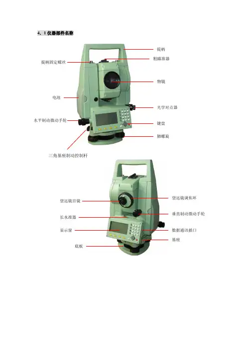
4.1仪器部件名称提柄物镜粗瞄准器光学对点器键盘 脚螺旋提柄固定螺丝电池水平制动微动手轮三角基座制动控制杆望远镜目镜长水准器 显示窗底板望远镜调焦环垂直制动微动手轮数据通讯插口 基座7.架设仪器注意:整平仪器前应先装上电池,因为装上电池后仪器会发生微小的倾斜。
(1) 将三脚架打开,伸长到适当高度,拧紧三个固定螺丝。
(2) 将仪器安装在三脚架上,然后拧紧连接螺丝。
(3) 利用圆水准器粗略整平仪器①旋转两个脚螺旋A 、B,使圆水准器气泡移到与上述两个脚螺旋连线垂直的水泡中心线上。
②旋转脚螺旋C ,使圆水准器气泡居中 。
(4) 利用长水准器精确整平仪器:①松开水平制动螺旋,水平旋转仪器使长水准器平行于某一对脚螺旋的连线AB ,旋转A 、B 两个脚螺旋使长水准器气泡居中。
②将仪器绕竖轴旋转90°(100g),旋转第三个脚螺旋C,使长水准器管气泡居中,再次旋转90°(100g),重复①、②步骤,直至四个位置处的长水准器管气泡始终居中为止。
(5) 利用光学对点器对中:调节光学对点器的目镜,看清对点器分划板。
松开三角架上的中心手把,轻移仪器,使光学对点器的中心标志对准测站点。
注意:尽量平移仪器,不要让仪器在架头上有转动,以尽量减少气泡的偏移。
(6) 最后精确整平仪器按第(4)步精确整平仪器,直到仪器旋转到任何位置时,长水准器气泡始终居中为止,最后拧紧中心手把。
8.调焦与照准注意:● 照准时如有强烈阳光直接进入物镜可能会造成仪器功能失灵,此时应使用物镜遮光罩。
● 当改变盘位观测时,用十字丝同一位置照准目标。
角螺旋B 角螺旋C角螺旋A测站点中心标记(1)目镜调焦:用望远镜观察一明亮无地物的背景。
将目镜顺时针旋到底,再逆时针慢慢旋转至十字丝成像最清晰(目镜调焦不需要经常进行)。
(2)照准目标:松开垂直和水平制动手轮,用粗瞄准器照准目标使其进入视场后固紧两制动手轮。
(3)物镜调焦:旋转望远镜调焦环至目标成像最清晰。
FARO ARM三坐标测量机基本操作过程一.重型三角架1.1三角架底座的移动1.1.1升起三角架底座1.1.1.1脚踩在脚踏板上,将其向下并朝向三角架中心压动,同时握住三角架稳定杆,向上提起,使三角架底座升起,确定只有滚动轮接触地面,以便将三角架移动到需要的位置。
1.1.1.2将脚从脚踏板上移走,脚踏板将锁定在适当位置。
1.1.2 降下三角架底座:脚踩在脚踏板上,将其向下并向三角架中心向外压动,使三角架的底座下降,滚动轮回缩,然后,弹起脚踏板。
1.1.3 固定三角架:手动调整三个调整螺钉,直到平稳,然后用扳手将三角架底座上的锁紧螺母锁定,防止三角架在不平坦的地面摇晃。
1.2调整三角架1.2.1升起三角架立柱1.2.1.1将锁紧手柄逆时针方向旋动,放松夹具,使立柱可以上下移动。
1.2.1.2逆时针方向旋动升降手柄,调整三角架立柱到希望高度。
1.2.1.3锁紧锁紧手柄,推下顶舌,使立柱固定不动。
1.2.2降低三角架立柱1.2.2.1将锁紧手柄逆时针方向旋动,放松夹具,使立柱可以上下移动。
1.2.2.2逆时针方向旋动四方手柄大约1英寸,将顶舌抬起。
1.2.2.3顺时针方向旋动四方手柄,使立柱降低。
1.2.2.4锁紧锁紧手柄,使立柱锁定在固定位置。
二.安装FARO ARM:正确的安装方法是保证测量精度的基础。
2.1将快速安装卡盘安装到三角架底座安装面板上,拧紧固定螺栓。
2.2将FARO ARM的下底座安装到快速安装盘上,并用扳手拧紧。
2.3选择所需用的测头安装到FARO ARM上,注意用力适度,以免损伤螺纹和影响测量精度。
2.4注意:三角架最好安装在水平面上,坡度较大时要防止ARM 坠落摔伤。
ARM暂时不用时要把第2和第6关节相对放置,并用臂固定贴固定好。
三.选择相应的校准器(球校准器或锥校准器),并固定在FARO ARM臂长的1/2-2/3范围处,以备FARO ARM校准之用。
四.连接计算机和FARO ARM4.1将端口锁(加密狗)插入到计算机的USB接口上,以授权CAM2正常运行。
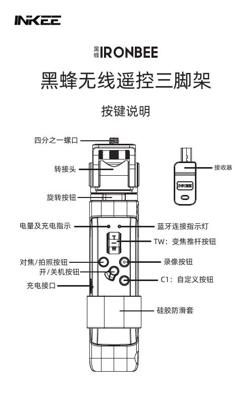
黑蜂无线遥控三脚架按键说明TW:变焦推杆按钮蓝牙连接指示灯录像按钮C1:自定义按钮硅胶防滑套接收器对焦/拍照按钮旋转按钮转接头四分之一螺口开/关机按钮充电接口电量及充电指示产品清单使用本产品前,请仔细检查产品包装内是否包含以下所有物品,若有缺失,请联系INKEE客服或您的代理商。
黑蜂三脚架×1接收器×1USB type-C充电线×1说明书×1转接头可以单方向的0°~90°弯折。
遥控器可拆卸。
对焦/拍照按钮为双段开关,轻按对焦,重按拍照。
遥控器对焦/拍照按钮配对方式拍照录像变焦1.确认遥控器开关按钮处于打开位置;2.选择相机蓝牙设置—开启蓝牙—选择相机与蓝牙遥控器配对;3.同时长按遥控器C1按钮+录像按钮直到蓝色指示灯快闪后松手,右边指示灯常亮即配对完成。
1.将接收器插入索尼相机的multi口;2.确认遥控器开关按钮处于打开位置;3.同时长按遥控器C1按钮+录像按钮直到蓝色指示灯快闪完毕后松手,右边指示灯常亮即配对完成。
1.确认遥控器开关按钮处于打开位置; 2.将相机的驱动模式设为<遥控>或<自拍:10秒/遥控>;3.选择相机蓝牙设置—开启蓝牙—选择相机与蓝牙遥控器配对;4.同时长按遥控器C1按钮+录像按钮直到蓝色指示灯快闪完毕后松手,右边指示灯常亮即配对完成。
与相机C1按钮相同无1.双击进入延时摄影,单击退出;2.长按C1键3秒可关闭相机。
蓝牙接收器(仅适用索尼相机使用)佳能相机自带蓝牙索尼相机C1按钮功能√√√√√√√√√√√√轻按对焦·是否可以保留多台索尼的配对信息?否,只可保留最近一台使用的相机配对信息或接收器信息。
·接收器的使用把接收器插入索尼相机multi接口即可。
·是否可以连接手机?是,遥控器可以连接手机(华为手机可以控制变焦、拍照),其他手机仅限于控制手机拍照。
·是否可以同时连接多台相机或手机?是,遥控器可以支持一台相机(接收器)和两台手机同时连接。
测绘三脚架的复位装置说明书设计背景我们测量中经常要碰到三脚架或者外面因素对脚手架的移动的误差,重读测量,使用我们的测绘三脚架姿态复位装置,可使其恢复到原来的位置,避免人工去再次重新测量,提高了效率,节约了时间。
基本思路:我们测量中经常要碰到三脚架或者其他因素对脚手架的移动的误差,重读测量,我们希望可以通过使用一些有效且简单的方法,使其恢复到原来的位置,避免人工去再次定位,提高效率,节约时间。
用全站仪测量各点的高程时,由于自然因素或人为因素的影响,会使三脚架的脚的位置发生移动,从而导致全站仪位置的移动,使测量无法继续进行。
需要人工再次定位,重新测量!我们在想是否可以通过使用一些有效且简单的方法,使全站仪恢复到原来的位置,避免人工去再次定位、重新测量,提高效率,节约时间。
创新点在原有的脚手架三脚架上进行了改进,使三脚架具有了复位的功能,避免了人为因素对这个造成影响从而重新定位。
技术关键如何使三脚架精确的恢复到原来的位置,通过做标记或者用软尺测距法,对原来的点位以及高度进行准确定位,达到方便测量。
主要技术指标高度的定位以及角度的定位。
在现有生活中我们都知道三脚架都是容易固定,同时也是容易被外界碰到或者其他因素从而造成三脚架的位移,现有技术并不能很好的控制这些外界因素的影响,我们的创新点是通过不能避免这些额外的因素,通过对三脚架的标记、修正的办法从而到达三脚架的复位,避免需要人工重新去再次移动到上一个点位,从头开始测量,可以直接在原来的点上进行测量,而且测量的误差可以降至很低,在一定程度上提高了测量的效率,以及测量的速度。
我们发明的三脚架回复装置如图所示,在原有的三脚架基础上增加了三把尺子跟一个空桶立柱,空桶立柱跟三脚架螺丝线连接,相当于加长了螺丝,在空桶立柱的下面安装有小平台,上面有印有mm刻度盘。
三根尺子分别绑定在三脚架的三个腿上,当我们需要测量时对三脚架对准、整平,然后把三把尺子搭载在平台上,上面有相应的刻度与之对应。

Rock Solid Tripods Beta and Gamma 180 Carbon or AluminiumBedienungsanleitung . . . . . . . . . .4User manual . . . . . . . . . . . . . . . . .8Manuel d‘utilisation . . . . . . . . . .12 Instrucciones de uso . . . . . . . . . .16 Istruzioni di utilizzo . . . . . . . . . .20Manual de utilização . . . . . . . . .24用戶手冊 . . . . . . . . . . . . . . . . . . .28用户手册 . . . . . . . . . . . . . . . . . . .3234Bedienungsanleitung für professionelles Stativ mit dreh- und schwenkbarer Mittelsäule5Anti-Rutsch Basisplatte HerausziehenVor dem Zusammenklappen die Mittelsäue auf die Markierung ausrichten Beinwinkelarretierung SchaumstoffgriffAusziehbarer Ballasthaken zum Anbringen eines GegengewichtesArretierung der Schnellverschlüsse: Sollten die Klemmverschlüsse durch häufigen Gebrauch locker werden, können diese mit einem Inbusschlüssel nachgezogen werden.Achtung: Drehen Sie die Arretierungsschraube nicht mehr als 45°. Sie kön-nen sonst die Klemmverschlüsse oder das Stativbein beschädigen! Dadurch erlischt der Garantieanspruch!Konterschrauben zum sicheren Fixieren Y-förmige Mittelsäule FeststellknopfSollten sich die Schrauben lösen, nutzen Sie zwei 4 mm Inbusschlüssel, um diese wieder festzuziehen.Schnellverschluss Bein ausziehenAufgedruckte Skalierung: Einfach einstellbare BeinlängeGummifuß mit integrierten Spikes: Der universelle Gummifuß ist ideal für einen stabilen Kontakt zum Untergrund. Die Spikes sind für den Gebrauch auf feuchtem oder weichem Boden entwickelt.12345678910111213141512 Achtung: Bitte verschließen Sie den Feststell k nopf für die Schwenk-funktion, wenn Sie diese nicht nutzen. Dadurch bleibt die Mittelsäule in der richtigen Position und verkratzt nicht.11Feststellknopf für Schwenkfunktion Mittelsäulen FeststellknopfFALSCH!RICHTIG!Drücken Sie den Schnellverschluss herunter, um den Winkel jedes Beines individuell zu verstellen:Hoch MittelNiedrig6Um das Stativ in der niedrigsten Position zu verwenden, nutzen Sie die kurze Mittelsäule. Sie bietet 360 ° horizontale und 180° vertikale Einstellungen.Mittelsäulen-FeststellknopfFeststellknopf für Schwenkfuntkion Feststellknopf für PanoramafunktionKurze Mittelsäule für niedrigste PositionierungUm die Mittelsäule zu wechseln, lösen Sie mit dem 3 mm Inbusschlüssel dieSchraube unterhalb der Basisplatte (A). Eine Umdrehung der Schraube genügt, um die Platte zu lösen. Schrauben Sie dann die Basisplatte (B) sowie den Ballasthaken ab. Entfernen Sie die Standard-Mittelsäule und ersetzen diese durch die kurze Mittelsäule. Schrauben Sie anschließend die Basisplatte wieder an. Bitte beachten Sie, dass die kurze Mittelsäule am unteren Ende eine Sicherung hat. Wenn Sie die kurze Mittelsäule wieder entnehmen wollen, drehen Sie den Sicherheitsverschluss so, dass die Mittelsäule herausgenommen werden kann.123Automatischer SicherheitsverschlussSetzen Sie die kurze Mittelsäule ein und drehen Sie den automatischen Sicher-heitsverschluss um 120° gegen den Uhrzeigersinn. Der Sicherheitsverschluss verhindert ein versehentliches Herausfallen der kurzen Mittelsäule. Wenn Sie den Sicherheitsverschluss erneut gegen den Uhrzeigersinn um 120° drehen, dann können Sie die kurze Mittelsäule wieder herausnehmen.DrehenHerausnehmen oder einsetzen AutomatischerSicherheitsverschluss1237Horizontale Positionierung der MittelsäuleAchten Sie auf den Schwenkpunkt, um ein Umkippen des Statives zu verhindern.3-Wege Mittelsäule mit FixierungDie Mittelsäule kann für Natur- oder Makroaufnahmen horizontal, vertikal oder über Kopf verwendet werden. Sie erlaubt 360° horizontale und 180° vertikale Einstel-lungen. Die Mittelsäule kann schnell und einfach mit dem Festellknopf positioniert werden.Hinweis:Um mögliche Schäden an der Fotoausrüstung durch ein Umkippen des Statives zu vermeiden, sollte bei Aufnahmen mit seitlich ausgeklappter Mittelsäule immer einpassendes Gegengewicht an dem Stativ befestigt werden.8User Guide for Professional Universal Tripod with Built-In 3-Way Center Column912312111189101514131276543-WAY LOCKCenter Column LockCORRECT!Wrong!Attention: Please lock the 3-Way lock if the 3-way function as lateral arm is not used. Therefore the center column will keep the right position and won‘t get scratched.High Medium LowPush the leg angle adjustment knob to set different angles individually on every leg:Non-slip platform Pull outBefore the tripod will be folded, Align the center column to the mark shown on the shoulder.Leg angle adjustement Foam hand gripHook for counter weightAdjustment for quick lock: If the quick lock loosens after prologed use, use the allen wrench to tighten.Attention: Do not tighten the screws more than 45 degree. Otherwise the quick locks or the tripod leg can be damaged. The the warranty expires!Anti-twist screws for secure fixing Y-tube center column Locking knobUse the two 4 mm allen wrenches to tighten the screws if they loosen.Quick locking system Pull out the legPrinted scale: Easy to set up leg tube lengthRubber feet with integrated Spikes: The universal rubber foot is ideal for every ground that needs a stable stand. The spikes are designed to be used in a wet or soft soil10123123To use the tripod in the lowest position please use the short center column. It provides 360 degrees horizontal and 180 degrees vertical adjustments.Center column locking knob Tilt locking knob Pan locking knobShort center column for lowest positionTo change the center colum, loosen the screw below the platform by using the 3mm allen wrench (A). One turn is enough to loosen the platform. Then unscrew the platform (B) as well as the hook at the bottom of the center column. Remove the standard center column and insert the short one. Afterwards screw on the platform again. Please note that the short center column has a safety lock at the bottom. If you want to take out the short center column you need to bring the safety lock into a position that the center column can be removed.Auto Safety LockInsert the auto safety lock to the slot of tripod, rotate the short center column anticlockwise to 120 degrees, push the short center column to the slot of tripod. The auto safety lock will lock automatically and prevent the short center column for accidently fall off. Rotate the auto safety lock anticlockwise to 120 degrees then pull out the short center column.Rotate the lock Take out or insert Auto Safety Lock113-Way Center Column with anti-twistThe center column can be used up side down, vertical or horizontal as a lateral arm for nature and macro photography. It allows 360° horizontal an 180°vertical adjustment. The column can be positioned and set-up quickly with the locking knob.Note:To avoid any damages of the photographic equipment through an overturning of the tripod when shooting with laterally unfolded center column, the tripod shouldalways be secured with an appropriate counterweight.Horizontal position for lateral arm,please be aware of the gravity to avoid that the tripod will fall down.12Instructions pour Trépied Professionnel avec colonne orientable intégréeFRANÇAIS131234567121115141312111098Blocage 3DBlocage colonneOUI!Non!Attention: Verrouiller systéma-tiquement le blocage 3D lorsque vousutilisez la fonction 3D en bras latéral.Cela garantit la bonne position de lacolonne central pour évitier une chutedu trépied.Haut Medium BasPousser le bouton d‘ajustement permetde régler individuellement l‘angle dechaque jambe:Plateforme antidérapanteSoulevezAlignez la marque avant d‘insérer la colonne.Ajustement de l‘angle des jambesPoignée en mousseCrochet rétractable pour contrepoidsAjustement du levier de verrouillage rapide:Si le levier de verrouillage rapide se desserre aprés une utilisation prolongée, utilisez la clé Allen pour le resserrer.Attention: Ne serrez pas la clé Allen à plus de 45 °.Vous pourriez endommager les tubes et perdre la grantie!Vis anti-torsion pour plus de sécurité.Colonne centrale en YBouton de blocadeTirez le levier pour ajuster I‘angle des jambes.Levier de verrouillage rapide.Dépliez la jambeMarquage gradué: Facilite la sélection de la longueur des jambesPied caoutchouc avec les crampons: Le pied en caoutchouc universel assure un contact ferme avec le sol. Les crampons sont concues pour une utilisation sur sols humides, sur graviers ou sols rocheux14123123Blocage automatique de sécuritéInsérez le bouton de blocage automatique dans le trépied, tournez la colonne courte de 120 ° dans le sens inverse des aiquilles d‘une montre, puis enfoncez la colonne courtle dans le trépied. Le blocage automatique se bloquera automa-tiquement pour éviter une chute accidentelle de la colonne central. Tournez le bouton de blocage automatique de 120 ° dans le sens inverse des aigulles d‘une montre puis retirez la colonne courte.TournezInsérez ou retirez Blocage automatique de sécuritéPour utiliser le trépied dans la position la plus basse, utilisez la colonne centrale courte. Cela permet des ajustements horziontaux à 360 ° et verticaux à 180 °, facilement et rapidement.Bouton de blocage de la colonne centrale Bouton de blocage de I‘inclinaison Blocage du panoramiqueColonne courte poir position basse pour utiliser la colonne courte Pour changer la colonne centrale, desserrer la clé Allen de 3 mm la vis en dessous de la plaque de base (A). Une rotation de la vis est suffisant pour desserrer la pla-que. Puis dévisser la plaque de base (B) et le crochet de ballast. Retirez la colonne centrale standard et la remplacer par la colonne courte. Visser ensuite à nouveau la plaque de base. S‘il vous plaît noter que la colonne centrale courte à l‘extrémité inférieure a une sauvegarde. Si vous voulez prendre à nouveau la colonne centrale courte, tourner le verrou de sécurité de telle sorte que la colonne centrale peut être retirée.FRANÇAIS15Marquage graduéLa colonne centrale peut ètre utilisée inversée oucomme un bras horizontal pour la photographie macro et de nature. Cela permet des ajustements horziontaux à 360° et verticaux à 180 °. La colonnepeut ètre posi-tionnée et mise en place rapidementà l‘aide dubouton de blocage.Consigne:Pour prévenir des dommages sur l’équipement photo résultant d’un renversement du trépied, il faut toujours fixer un contrepoids adapté en cas de prises de vueavec la colonne centrale déployée sur le côté.Position horizontale pour bras latéral,prenez garde au centre de gravité pour éviter la chute du trépied.16Instrucciones de uso para trípode profesional con colum-na central giratoria y rotatoriaESPAÑOL171231211118910151413127654Botón de ajuste para la función de giro Botón de ajuste de la columna central¡CORRECTO!¡INCORRECTO! Atención: Por favor, cierre el botón de ajuste para la función de giro, si no se está utilizando. Así la columna central quedará en la posición correcta y evitará que se raye.Alto Medio BajoEmpuje hacia abajo el cierre rápido para ajustar el ángulo de las patas de forma individual:Placa base antideslizante SacarAlinear la marca antes de cerrar la columna central Dispositivo de bloqueo del ángulo de las patas Agarre de gomaespumaGancho extraíble para saco de arena o contrapesoDispositivo de bloqueo del cierre rápido: Si el cierre se afloja, debido al uso frecuente, puede apretarlo con una llave Allen.Atención: No gire el tornillo de bloqueo más de 45º.Podría dañar el cierre o la pata del trípode. Si lo hace, perdería la garantía.Tornillo antitorsión para una mayor seguridad Columna central en forma de Y Botón de bloqueoSi se aflojan los tornillos, use dos llaves Allen de 4 mm para apretarlos. Sistema de cierre rápido Sacar la pataEscala impresa: Longitud de las patas fácil de ajustarPies de goma con el juego de clavos integrado: El pie de goma uni-versal asegura un contacto firme con el suelo. Los clavos están diseñados para usarse en suelos húmedos, en grava o suelos rocosos18123123Para utilizar el soporte en la posición más baja, utilice la columna corta. Proporci-ona un ajuste de 360º en horizontal y de 180º en vertical; rápido y fácil.Botón de ajuste de la columna central Botón de ajuste para la función de giro Botón de ajuste para la función panorámicaColumna central corta para la posición más bajaPara cambiar la columna central, afloje la llave Allen de 3 mm el tornillo debajo de la placa base (A). Una revolución del tornillo es suficiente para aflojar la placa. Luego desatornillar la placa de base (B) y el gancho de lastre. Retire la columna central estándar y sustituirlo por el de columna corta. A continuación, el tornillo de la placa de base de nuevo. Tenga en cuenta que la columna de centro corto en el extremo inferior tiene una copia de seguridad. Si usted quiere tomar la columna de centro corto de nuevo, gire el cierre de seguridad de manera que la columna central se puede quitar..ESPAÑOLCierre de seguridad automáticoColoque la columna central corta y gire el cierre de seguridad 120º en sentido contrario a las agujas del reloj. El cierre de seguridad evitará que la columna corta se caiga accidentalmente. Cuando gire de nuevo el cierre de seguridad 1201 en sentido contrario a las agujas del reloj, podrá retirar la columna corta.GirarSacar o insertarBloqueo de seguridad automático19Columna central de 3 vías con antitorsiónLa columna central se puede usar para tomas macro o naturales por encima de la cabeza, de forma invertida o en horizontal. Proporciona un ajuste de 360º en horizontal y de 180º en vertical. La columna puede colocarse de forma rápida y sencilla con el botón de ajuste.Nota:Para evitar posibles daños en el equipo fotográfico en caso de volcarse el trípode, cuando se dispara con la columna central habría que asegurar el trípode con uncontrapeso adecuado.Posición horizontal de la columna centralPreste atención al centro de gravedad para evitar que el trípode se vuelque..20Istruzioni per l‘uso per cavalletto professionale con colonna centrale rotante e oscillanteITALIANO211232111118910151413127654Pulsante di blocco per funzionepanoramicaPulsante di blocco colonna centraleCORRETTO!Errato!Attenzione: Si prega di chiudereil pulsante di blocco per la funzionepanoramica qualora questa non vengautilizzata. In questo modo la colonnacentrale rimarrà in posizione corretta esi eviteranno eventuali graffiAlta Media BassaSpingere verso il basso la chiusura rapidaper regolare singolarmente l‘angolazionedi ciascuna gamba:Base di appoggio antiscivoloEstrarrePrima di ripiegare la struttura, allineare la colonna centrale con la marcatura.Blocco dell‘angolazione della gambaImpugnatura in schiumaGancio estraibile per sacco di sabbia o contrappesoBlocco della chiusura rapida: Qualora i morsetti dovessero allentarsi a causa dell‘uso frequente, possono essere serrati con una chiave a brugola.Attenzione: Non ruotare la vite di arresto per più di 45°. In caso contrario si rischia di danneggiare i morsetti o la gamba del cavalletto! La garanzia ne risulterebbe inoltre invalidata.Viti anti rotazione per una sicurezza aggiuntivaColonna centrale a forma di YPulsante di bloccoQualora le viti dovessero allentarsi, utilizzare la chiave a brugolada 4 mm per fissarle.Chiusura rapidaEstrarre la gambaScala stampata: Lunghezza della gamba facilmente regolabilePiede in gomma con punte integrato: Piede in gomma universale per un contatto stabile con il terreno. Le punte sono state sviluppate per essere utilizzate su terreno umido, roccioso o ghiaia.22123123Per utilizzare il supporto nella posizione più bassa, utilizzare la colonna corta. Così facendo è possibile usufruire di una possibilità di regolazione a 360° in orizzonta-le e a 180° in verticale, in modo semplice e veloce.Pulsante di blocco colonna centrale Pulsante di blocco funzione panoramica Pulsante di blocco funzione panoramicaColonna centrale corta per raggiungere posizioni molto bassePer modificare la colonna centrale, allentare la chiave a brugola da 3 mm, la vite sotto la piastra di base (A). Una rotazione della vite è sufficiente allentare la piastra. Quindi svitare la piastra di base (B) e il gancio di zavorra. Rimuovere la colonna centrale di serie e sostituirlo con la colonna corta. Poi riavvitare la piastra di base. Si prega di notare che la colonna centrale corta all‘estremità inferiore ha una copia di backup. Se si vuole prendere di nuovo la colonna centrale corta, ruotare il blocco di sicurezza in modo che la colonna centrale può essere rimosso..ITALIANOChiusura di sicurezza automaticaInserire la colonna centrale corta e ruotare la chiusura di sicurezza automatica di 120° in senso antiorario. La chiusura di sicurezza impedisce che la colonna cent-rale corta cada accidentalmente. Ruotando nuovamente la chiusura di sicurezza di 120° in senso anti orario, è possibile estrarre nuovamente la colonna centrale corta.RuotareEstrarre o inserire Chiusura di sicurezza automatica23Colonna centrale tridirezionale con dispositivo di sicurezza anti rotazioneLa colonna centrale può essere utilizzata per scatti naturali o macro dall‘alto, sottosopra o in orizzontale. Consente una regolazione di 360° in orizzontale e di 180° in verticale. La colonna centrale può essere posizio-nata in modo semplice e veloce con il pulsante di blocco.Nota:Al fine di evitare eventuali danni di apparecchiature fotografiche attraverso un ribaltamento del treppiede quando si scatta con colonna centrale laterale spiega-to, il treppiede deve sempre essere assicurato con un contrappeso adeguato.Posizione orizzontale della colonna centraleSi prega di prestare attenzione al punto di articolazione per evitare che il24Manual do utilizador para tripé profissional com coluna central rotativa e orientávelPORTUGUÊS251232111118910151413127654Botão de ajuste para função orientávelBotão de ajuste colunas centraisCORRETO!Errado!Atenção: Feche o botão de ajuste para a função orientável quando não a estiver a utilizar. Assim, a coluna central mantém-se na posição correta e não risca.Alto Médio BaixoPressione o fecho rápido para baixo, de modo a ajustar individualmente o ângulo de cada perna:Placa de base anti-derrapante Puxar para foraAlinhe com a marca antes de inserir a coluna central.Bloqueio do ângulo das pernas Punho de espumaGancho retrátil para saco de areia ou contra-pesoTravamento dos fechos rápidos: Caso os fechos de retenção fiquem mais soltos devido à frequente utilização, os mesmos podem ser apertados com uma chave sextavada.Atenção: Nunca rode o parafuso de travamento acima de45 °, porque pode danificar os fechos de retenção ou a perna do tripé! Tal levará à perda do direito a garantia!Parafusos anti-torsão para uma segurança extra.Coluna central em forma de Y Botão de bloqueioCaso os parafusos se soltem, utilize a chave sexatavada de 4 mm para os fixar.Fecho rápido Puxar a pernaEscalonamento impresso: Comprimento das pernas de fácil ajuste Pé de borracha para com ponteiras: O pé de borracha universal para um contacto estável com o solo. As ponteiras foram desenvolvidas para a utilização em solos húmidos, sobre cascalho ou solo rochoso26123123Para usar o suporte na posição mais baixa, use a coluna curta. Esta oferece um ajuste horizontal de 360 ° e vertical de 180 ° simples e rápido..Botão de ajuste colunas centraisBotão de ajuste para função orientável Botão de ajuste para função panorâmicaColuna central curta para um posicionamento mais baixoPara alterar a coluna central, solte a chave Allen 3 mm, o parafuso debaixo da placa de base (A). Uma rotação do parafuso é suficiente para soltar a placa. em seguida, desapertar a placa de base (B) e o gancho de lastro. Remova a coluna central padrão e substituí-la pela coluna curta. Em seguida, fixe a placa de base novamente. Por favor, note que a coluna curta centro na extremidade inferior tem um backup. Se você quer tomar a coluna central curta novamente, ligar o bloqueio de segurança para que a coluna central pode ser removida.PORTUGUÊSBloqueio de segurança automáticoInsira a coluna central curta e rode o fecho de segurança automático em 120 ° no sentido anti-horário. O fecho de segurança impede uma queda acidental da coluna central. Quando rodar novamente o fecho de segurança em 120 ° contra o sentido horário, poderá retirar novamente a coluna central curta.RodarRetirar ou inserir Fecho de segurança automático27Coluna central de 3 vias com dispositivo anti-torsãoA coluna central pode ser utilizada invertida ou na horizontal para fotografar na natureza ou para a foto-grafia macro. A mesma permite um ajuste horizontal de 360 ° e vertical de 180 °. A coluna central pode ser posicionada de forma rápida e simples com o botão de ajuste.Nota: Para evitar qualquer dano no equipamento fotográfico provocado por uma queda do tripé quando fotografa com coluna central inclinada, este deve tersempre colocado um contrapeso apropriadoPosicionamento horizontal da coluna centralTenha atenção ao centro de gravidade, de modo a evitar que o tripé caia.內置三路中軸專業通用三腳架用戶指南282912345671112151413121110983路鎖 中軸鎖正確!錯誤!注意: 如果不使用橫軸之類的三路功能,請鎖緊三路鎖。
测绘三脚架的复位装置说明书
设计背景
我们测量中经常要碰到三脚架或者外面因素对脚手架的移动的误差,重读测量,使用我们的测绘三脚架姿态复位装置,可使其恢复到原来的位置,避免人工去再次重新测量,提高了效率,节约了时间。
基本思路:我们测量中经常要碰到三脚架或者其他因素对脚手架的移动的误差,重读测量,我们希望可以通过使用一些有效且简单的方法,使其恢复到原来的位置,避免人工去再次定位,提高效率,节约时间。
用全站仪测量各点的高程时,由于自然因素或人为因素的影响,会使三脚架的脚的位置发生移动,从而导致全站仪位置的移动,使测量无法继续进行。
需要人工再次定位,重新测量!我们在想是否可以通过使用一些有效且简单的方法,使全站仪恢复到原来的位置,避免人工去再次定位、重新测量,提高效率,节约时间。
创新点
在原有的脚手架三脚架上进行了改进,使三脚架具有了复位的功能,避免了人为因素对这个造成影响从而重新定位。
技术关键
如何使三脚架精确的恢复到原来的位置,通过做标记或者用软尺测距法,对原来的点位以及高度进行准确定位,达到方便测量。
主要技术指标
高度的定位以及角度的定位。
在现有生活中我们都知道三脚架都是容易固定,同时也是容易被外界碰到或者其他因素从而造成三脚架的位移,现有技术并不能很好的控制这些外界因素的影响,我们的创新点是通过不能避免这些额外的因素,通过对三脚架的标记、修正的办法从而到达三脚架的复位,避免需要人工重新去再次移动到上一个点位,从头开始测量,可以
直接在原来的点上进行测量,而且测量的误差可以降至很低,在一定程度上提高了测量的效率,以及测量的速度。
我们发明的三脚架回复装置如图所示,在原有的三脚架基础上增加了三把尺子跟一个空桶立柱,空桶立柱跟三脚架螺丝线连接,相当于加长了螺丝,在空桶立柱的下面安装有小平台,上面有印有mm刻度盘。
三根尺子分别绑定在三脚架的三个腿上,当我们需要测量时对三脚架对准、整平,然后把三把尺子搭载在平台上,上面有相应的刻度与之对应。
当三脚架移动一个脚时,我们根据尺子读数将腿向内缩缩或者向外延伸,使钢尺与原来的刻度盘读数恢复到原来的读数,三脚架佳恢复到了原来的位置,操作简单,避免了再次对准整平,节约了时间。
当我们的三脚架移动两个腿时,因为三脚架本身结构就存在稳定性,再加上三脚架三只脚都是尖端,一般三脚架的移动都会是一只脚移动,当两只脚都移动时,三脚架整体都会移动,这样只能再次在对准整平。
用全站仪测量各点的高程时,由于自然因素或人为因素的影响,会使三脚架的脚的位置发生移动,从而导致全站仪位置的移动,使测量无法继续进行。
需要人工再次定位,重新测量!我们在想是否可以通过使用一些有效且简单的方法,使全站仪恢复到原来的位置,避免人工去再次定位、重新测量,提高效率,节约时间。
附图说明
图1 图2
图3 图4
图5 图6。