
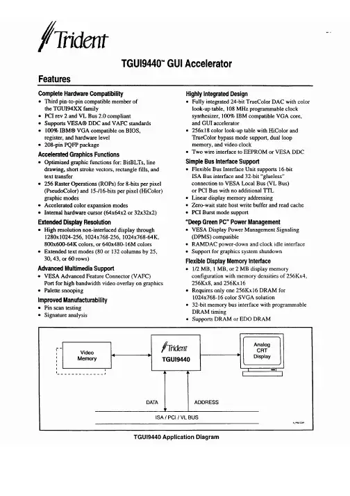
TGUI9440中文资料
- 格式:pdf
- 大小:606.75 KB
- 文档页数:4

M29F002BT, M29F002BNTM29F002BB, M29F002BNB 2 Mbit (256Kb x8, Boot Block) Single Supply Flash Memorys SINGLE 5V ± 10% SUPPLY VOLTAGE for PROGRAM, ERASE and READ OPERATIONSs ACCESS TIME: 45nss PROGRAMMING TIME–8µs by Byte typicals7 MEMORY BLOCKS–1 Boot Block (Top or Bottom Location)–2 Parameter and 4 Main Blockss PROGRAM/ERASE CONTROLLER–Embedded Byte Program algorithm–Embedded Multi-Block/Chip Erase algorithm –Status Register Polling and Toggle Bitss ERASE SUSPEND and RESUME MODES –Read and Program another Block during Erase Suspends UNLOCK BYPASS PROGRAM COMMAND –Faster Production/Batch Programmings TEMPORARY BLOCK UNPROTECTION MODEs LOW POWER CONSUMPTION–Standby and Automatic Standbys100,000 PROGRAM/ERASE CYCLES per BLOCKs20 YEARS DATA RETENTION–Defectivity below 1 ppm/years ELECTRONIC SIGNATURE–Manufacturer Code: 20h–Top Device Code M29F002BT: B0h–Top Device Code M29F002BNT: B0h–Bottom Device Code M29F002BB: 34h–Bottom Device Code M29F002BNB: 34h1/22April 2002M29F002BT, M29F002BB, M29F002BNT, M29F002BNB2/22Table 1. Signal NamesA0-A17Address Inputs DQ0-DQ7Data Inputs/Outputs E Chip Enable G Output Enable WWrite EnableRPM29F002BT, M29F002BB:Reset/Block Temporary UnprotectM29F002BNT, M29F002BNB:Not Connected InternallyV CC Supply Voltage V SSGround3/22M29F002BT, M29F002BB, M29F002BNT, M29F002BNBSUMMARY DESCRIPTIONThe M29F002B is a 2 Mbit (256Kb x8) non-volatile memory that can be read, erased and repro-grammed. These operations can be performed us-ing a single 5V supply. On power-up the memory defaults to its Read mode where it can be read in the same way as a ROM or EPROM. The M29F002B is fully backward compatible with the M29F002.The memory is divided into blocks that can be erased independently so it is possible to preserve valid data while old data is erased. Each block can be protected independently to prevent accidental Program or Erase commands from modifying the memory. Program and Erase commands are writ-ten to the Command Interface of the memory. An on-chip Program/Erase Controller simplifies the process of programming or erasing the memory by taking care of all of the special operations that are required to update the memory contents. The end Table 2. Absolute Maximum Ratings (1)Note: 1.Except for the rating "Operating Temperature Range", stresses above those listed in the Table "Absolute Maximum Ratings" maycause permanent damage to the device. These are stress ratings only and operation of the device at these or any other conditions above those indicated in the Operating sections of this specification is not implied. Exposure to Absolute Maximum Rating condi-tions for extended periods may affect device reliability. Refer also to the STMicroelectronics SURE Program and other relevant qual-ity documents.2.Minimum Voltage may undershoot to –2V during transition and for less than 20ns during transitions.SymbolParameterValue Unit T AAmbient Operating Temperature (Temperature Range Option 1)0 to 70°C Ambient Operating Temperature (Temperature Range Option 6)–40 to 85°C Ambient Operating Temperature (Temperature Range Option 3)–40 to 125°C T BIAS Temperature Under Bias –50 to 125°C T STG Storage Temperature –65 to 150°C V IO (2)Input or Output Voltage –0.6 to 6V V CC Supply Voltage –0.6 to 6V V IDIdentification Voltage–0.6 to 13.5VTable 4. Bottom Boot Block Addresses, M29F002BB#Size (Kbytes)Address Range 66430000h-3FFFFh 56420000h-2FFFFh 46410000h-1FFFFh 33208000h-0FFFFh 2806000h-07FFFh 1804000h-05FFFh 01600000h-03FFFhof a program or erase operation can be detected and any error conditions identified. The command set required to control the memory is consistent with JEDEC standards.The blocks in the memory are asymmetrically ar-ranged, see Tables 3A and 3B, Block Addresses.The first or last 64 Kbytes have been divided into four additional blocks. The 16 Kbyte Boot Block can be used for small initialization code to start the microprocessor, the two 8 Kbyte Parameter Blocks can be used for parameter storage and the remaining 32K is a small Main Block where the ap-plication may be stored.Chip Enable, Output Enable and Write Enable sig-nals control the bus operation of the memory.They allow simple connection to most micropro-cessors, often without additional logic.The memory is offered in TSOP32 (8 x 20mm),PLCC32 and PDIP packages and it is supplied with all the bits erased (set to ’1’).Table 3. Top Boot Block Addresses, M29F002BT, M29F002BNT#Size (Kbytes)Address Range 6163C000h-3FFFFh 583A000h-3BFFFh 4838000h-39FFFh 33230000h-37FFFh 26420000h-2FFFFh 16410000h-1FFFFh 06400000h-0FFFFhM29F002BT, M29F002BB, M29F002BNT, M29F002BNB4/22SIGNAL DESCRIPTIONSSee Figure 1, Logic Diagram, and Table 1, Signal Names, for a brief overview of the signals connect-ed to this device.Address Inputs (A0-A17).The Address Inputs select the cells in the memory array to access dur-ing Bus Read operations. During Bus Write opera-tions they control the commands sent to the Command Interface of the internal state machine.Data Inputs/Outputs (DQ0-DQ7).The Data In-puts/Outputs output the data stored at the selected address during a Bus Read operation. During Bus Write operations they represent the commands sent to the Command Interface of the internal state machine.the memory, allowing Bus Read and Bus Write op-erations to be performed. When Chip Enable is High, V IH , all other pins are ignored.trols the Bus Read operation of the memory.the Bus Write operation of the memory’s Com-mand Interface.The Re-set/Block Temporary Unprotect pin can be used to apply a Hardware Reset to the memory or to tem-porarily unprotect all blocks that have been pro-tected. On the M29F002BNT the pin is not connected internally and this feature is not avail-able.A Hardware Reset is achieved by holding Reset/Block Temporary Unprotect Low, V IL , for at least t PLPX . After Reset/Block Temporary Unprotect goes High, V IH , the memory will be ready for Bus Read and Bus Write operations after t PHEL or t PLYH , whichever occurs last. See Table 15 and Figure 12, Reset/Temporary Unprotect AC Char-acteristics for more details.Holding RP at V ID will temporarily unprotect the protected blocks in the memory. Program and Erase operations on all blocks will be possible.The transition from V IH to V ID must be slower than t PHPHH .Reset/Block Temporary Unprotect can be left un-connected. A weak internal pull-up resistor en-sures that the memory always operates correctly.V CC Supply Voltage.The V CC Supply Voltage supplies the power for all operations (Read, Pro-gram, Erase etc.).The Command Interface is disabled when the V CC Supply Voltage is less than the Lockout Voltage,V LKO . This prevents Bus Write operations from ac-cidentally damaging the data during power up,power down and power surges. If the Program/Erase Controller is programming or erasing during this time then the operation aborts and the memo-ry contents being altered will be invalid.A 0.1µF capacitor should be connected between the V CC Supply Voltage pin and the V SS Ground pin to decouple the current surges from the power supply. The PCB track widths must be sufficient to carry the currents required during program and erase operations, I CC4.V SS Ground.The V SS Ground is the reference for all voltage measurements.5/22M29F002BT, M29F002BB, M29F002BNT, M29F002BNBTable 5. Bus OperationsNote:X = V IL or V IH .OperationE G W Address Inputs DataInputs/Outputs Bus Read V IL V IL V IH Cell Address Data Output Bus Write V IL V IH V IL Command Address Data Input Output Disable X V IH V IH X Hi-Z StandbyV IH X X XHi-Z Read Manufacturer CodeV ILV ILV IHA0 = V IL , A1 = V IL , A9 = V ID , Others V IL or V IH20hRead Device CodeV IL V IL V IHA0 = V IH , A1 = V IL , A9 = V ID , Others V IL or V IHB0h (M29F002BT)B0h (M29F002BNT)34h (M29F002BB)BUS OPERATIONSThere are five standard bus operations that control the device. These are Bus Read, Bus Write, Out-put Disable, Standby and Automatic Standby. See Table 5, Bus Operations, for a summary. Typically glitches of less than 5ns on Chip Enable or Write Enable are ignored by the memory and do not af-fect bus operations.Bus Read.Bus Read operations read from the memory cells, or specific registers in the Com-mand Interface. A valid Bus Read operation in-volves setting the desired address on the Address Inputs, applying a Low signal, V IL , to Chip Enable and Output Enable and keeping Write Enable High, V IH . The Data Inputs/Outputs will output the value, see Figure 9, Read Mode AC Waveforms,and Table 12, Read AC Characteristics, for details of when the output becomes valid.Bus Write.Bus Write operations write to the Command Interface. A valid Bus Write operation begins by setting the desired address on the Ad-dress Inputs. The Address Inputs are latched by the Command Interface on the falling edge of Chip Enable or Write Enable, whichever occurs last.The Data Inputs/Outputs are latched by the Com-mand Interface on the rising edge of Chip Enable or Write Enable, whichever occurs first. Output En-able must remain High, V IH , during the whole Bus Write operation. See Figures 10 and 11, Write AC Waveforms, and Tables 13 and 14, Write AC Characteristics, for details of the timing require-ments.Output Disable.The Data Inputs/Outputs are in the high impedance state when Output Enable is High, V IH .Standby.When Chip Enable is High, V IH , the Data Inputs/Outputs pins are placed in the high-impedance state and the Supply Current is re-duced to the Standby level. When Chip Enable is at V IH the Supply Current is reduced to the TTL Standby Supply Current, I CC2.To further reduce the Supply Current to the CMOS Standby Supply Current, I CC3, Chip Enable should be held within V CC ± 0.2V. For Standby current levels see Table 11, DC Characteristics.During program or erase operations the memory will continue to use the Program/Erase Supply Current, I CC4, for Program or Erase operations un-til the operation completes.Automatic Standby.If CMOS levels (V CC ± 0.2V)are used to drive the bus and the bus is inactive for 150ns or more the memory enters Automatic Standby where the internal Supply Current is re-duced to the CMOS Standby Supply Current, I CC3.The Data Inputs/Outputs will still output data if a Bus Read operation is in progress.Special Bus OperationsAdditional bus operations can be performed to read the Electronic Signature and also to apply and remove Block Protection. These bus opera-tions are intended for use by programming equip-ment and are not usually used in applications.They require V ID to be applied to some pins.Electronic Signature.The memory has two codes, the manufacturer code and the device code, that can be read to identify the memory.These codes can be read by applying the signals listed in Table 5, Bus Operations.Block Protection and Blocks Unprotection.Each block can be separately protected against acci-dental Program or Erase. Protected blocks can be unprotected to allow data to be changed.There are two methods available for protecting and unprotecting the blocks, one for use on pro-gramming equipment and the other for in-system use. For further information refer to Application Note AN1122, Applying Protection and Unprotec-tion to M29 Series Flash.M29F002BT, M29F002BB, M29F002BNT, M29F002BNB6/22COMMAND INTERFACEAll Bus Write operations to the memory are inter-preted by the Command Interface. Commands consist of one or more sequential Bus Write oper-ations. Failure to observe a valid sequence of Bus Write operations will result in the memory return-ing to Read mode. The long command sequences are imposed to maximize data security.The commands are summarized in Table 6, Com-mands. Refer to Table 6 in conjunction with the text descriptions below.Read/Reset Command.The Read/Reset com-mand returns the memory to its Read mode where it behaves like a ROM or EPROM. It also resets the errors in the Status Register. Either one or three Bus Write operations can be used to issue the Read/Reset command.If the Read/Reset command is issued during a Block Erase operation or following a Programming or Erase error then the memory will take upto 10µs to abort. During the abort period no valid data can be read from the memory. Issuing a Read/Reset command during a Block Erase operation will leave invalid data in the memory.Auto Select Command.The Auto Select com-mand is used to read the Manufacturer Code, the Device Code and the Block Protection Status.Three consecutive Bus Write operations are re-quired to issue the Auto Select command. Once the Auto Select command is issued the memory remains in Auto Select mode until another com-mand is issued.From the Auto Select mode the Manufacturer Code can be read using a Bus Read operation with A0 = V IL and A1 = V IL . The other address bits may be set to either V IL or V IH . The Manufacturer Code for STMicroelectronics is 20h.The Device Code can be read using a Bus Read operation with A0 = V IH and A1 = V IL . The other address bits may be set to either V IL or V IH . The Device Code for the M29F002BT is B0h, the M29F002BNT is B0h and the M29F002BB is 34h.The Block Protection Status of each block can be read using a Bus Read operation with A0 = V IL ,A1=V IH , and A13-A17 specifying the address of the block. The other address bits may be set to ei-ther V IL or V IH . If the addressed block is protected then 01h is output on the Data Inputs/Outputs, oth-erwise 00h is output.Program Command.The Program command can be used to program a value to one address in the memory array at a time. The command re-quires four Bus Write operations, the final write op-eration latches the address and data in the internalstate machine and starts the Program/Erase Con-troller.If the address falls in a protected block then the Program command is ignored, the data remains unchanged. The Status Register is never read and no error condition is given.During the program operation the memory will ig-nore all commands. It is not possible to issue any command to abort or pause the operation. Typical program times are given in Table 7. Bus Read op-erations during the program operation will output the Status Register on the Data Inputs/Outputs.See the section on the Status Register for more details.After the program operation has completed the memory will return to the Read mode, unless an error has occurred. When an error occurs the memory will continue to output the Status Regis-ter. A Read/Reset command must be issued to re-set the error condition and return to Read mode.Note that the Program command cannot change a bit set at ’0’ back to ’1’. One of the Erase Com-mands must be used to set all the bits in a block or in the whole memory from ’0’ to ’1’.Unlock Bypass Command.The Unlock Bypass command is used in conjunction with the Unlock Bypass Program command to program the memo-ry. When the access time to the device is long (as with some EPROM programmers) considerable time saving can be made by using these com-mands. Three Bus Write operations are required to issue the Unlock Bypass command.Once the Unlock Bypass command has been is-sued the memory will only accept the Unlock By-pass Program command and the Unlock Bypass Reset command. The memory can be read as if in Read mode.Unlock Bypass Program Command.The Un-lock Bypass Program command can be used to program one address in memory at a time. The command requires two Bus Write operations, the final write operation latches the address and data in the internal state machine and starts the Pro-gram/Erase Controller.The Program operation using the Unlock Bypass Program command behaves identically to the Pro-gram operation using the Program command. A protected block cannot be programmed; the oper-ation cannot be aborted and the Status Register is read. Errors must be reset using the Read/Reset command, which leaves the device in Unlock By-pass Mode. See the Program command for details on the behavior.7/22M29F002BT, M29F002BB, M29F002BNT, M29F002BNBTable 6. CommandsNote:X Don’t Care, PA Program Address, PD Program Data, BA Any address in the Block.All values in the table are in hexadecimal.The Command Interface only uses address bits A0-A10 to verify the commands, the upper address bits are Don’t Care.Read/Reset. After a Read/Reset command, read the memory as normal until another command is issued.Auto Select. After an Auto Select command, read Manufacturer ID, Device ID or Block Protection Status.Program, Unlock Bypass Program, Chip Erase, Block Erase. After these commands read the Status Register until the Program/Erase Controller completes and the memory returns to Read Mode. Add additional Blocks during Block Erase Command with additional Bus Write Operations until the Timeout Bit is set.Unlock Bypass. After the Unlock Bypass command issue Unlock Bypass Program or Unlock Bypass Reset commands.Unlock Bypass Reset. After the Unlock Bypass Reset command read the memory as normal until another command is issued.Erase Suspend. After the Erase Suspend command read non-erasing memory blocks as normal, issue Auto Select and Program commands on non-erasing blocks as normal.Erase Resume. After the Erase Resume command the suspended Erase operation resumes, read the Status Register until the Program/Erase Controller completes and the memory returns to Read Mode.CommandL e n g t hBus Write Operations1st 2nd 3rd 4th 5th 6th Addr Data AddrDataAddrDataAddrDataAddrDataAddrDataRead/Reset 1X F03555AA 2AA 55X F0Auto Select 3555AA 2AA 5555590Program 4555AA 2AA 55555A0P APDUnlock Bypass 3555AA 2AA 5555520Unlock Bypass Program2X A0PA PD Unlock Bypass Reset 2X 90X 00Chip Erase 6555AA 2AA 5555580555AA 2AA 5555510Block Erase 6+555AA 2AA5555580555AA2AA55BA30Erase Suspend 1X B0Erase Resume1X30Unlock Bypass Reset Command.The Unlock Bypass Reset command can be used to return to Read/Reset mode from Unlock Bypass Mode.Two Bus Write operations are required to issue the Unlock Bypass Reset command.Chip Erase Command.The Chip Erase com-mand can be used to erase the entire chip. Six Bus Write operations are required to issue the Chip Erase Command and start the Program/Erase Controller.If any blocks are protected then these are ignored and all the other blocks are erased. If all of the blocks are protected the Chip Erase operation ap-pears to start but will terminate within about 100µs,leaving the data unchanged. No error condition is given when protected blocks are ignored.During the erase operation the memory will ignore all commands. It is not possible to issue any com-mand to abort the operation. Typical chip erase times are given in Table 7. All Bus Read opera-tions during the Chip Erase operation will output the Status Register on the Data Inputs/Outputs.See the section on the Status Register for more details.After the Chip Erase operation has completed the memory will return to the Read Mode, unless an error has occurred. When an error occurs the memory will continue to output the Status Regis-ter. A Read/Reset command must be issued to re-set the error condition and return to Read Mode.The Chip Erase Command sets all of the bits in un-protected blocks of the memory to ’1’. All previous data is lost.M29F002BT, M29F002BB, M29F002BNT, M29F002BNB8/22Block Erase Command.The Block Erase com-mand can be used to erase a list of one or more blocks. Six Bus Write operations are required to select the first block in the list. Each additional block in the list can be selected by repeating the sixth Bus Write operation using the address of the additional block. The Block Erase operation starts the Program/Erase Controller about 50µs after the last Bus Write operation. Once the Program/Erase Controller starts it is not possible to select any more blocks. Each additional block must therefore be selected within 50µs of the last block. The 50µs timer restarts when an additional block is selected.The Status Register can be read after the sixth Bus Write operation. See the Status Register for details on how to identify if the Program/Erase Controller has started the Block Erase operation. If any selected blocks are protected then these are ignored and all the other selected blocks are erased. If all of the selected blocks are protected the Block Erase operation appears to start but will terminate within about 100µs, leaving the data un-changed. No error condition is given when protect-ed blocks are ignored.During the Block Erase operation the memory will ignore all commands except the Erase Suspend and Read/Reset commands. Typical block erase times are given in Table 7. All Bus Read opera-tions during the Block Erase operation will output the Status Register on the Data Inputs/Outputs.See the section on the Status Register for more details.After the Block Erase operation has completed the memory will return to the Read Mode, unless an error has occurred. When an error occurs the memory will continue to output the Status Regis-ter. A Read/Reset command must be issued to re-set the error condition and return to Read mode.The Block Erase Command sets all of the bits in the unprotected selected blocks to ’1’. All previous data in the selected blocks is lost.Erase Suspend Command.The Erase Suspend Command may be used to temporarily suspend a Block Erase operation and return the memory to Read mode. The command requires one Bus Write operation.The Program/Erase Controller will suspend within 15µs of the Erase Suspend Command being is-sued. Once the Program/Erase Controller has stopped the memory will be set to Read mode and the Erase will be suspended. If the Erase Suspend command is issued during the period when the memory is waiting for an additional block (before the Program/Erase Controller starts) then the Erase is suspended immediately and will start im-mediately when the Erase Resume Command is issued. It will not be possible to select any further blocks for erasure after the Erase Resume.During Erase Suspend it is possible to Read and Program cells in blocks that are not being erased;both Read and Program operations behave as normal on these blocks. Reading from blocks that are being erased will output the Status Register. It is also possible to enter the Auto Select mode: the memory will behave as in the Auto Select mode on all blocks until a Read/Reset command returns the memory to Erase Suspend mode.Erase Resume Command.The Erase Resume command must be used to restart the Program/Erase Controller from Erase Suspend. An erase can be suspended and resumed more than once.Table 7. Program, Erase Times and Program, Erase Endurance Cycles (T A = 0 to 70°C, –40 to 85°C or –40 to 125°C)Note: 1.T A = 25 °C, V CC = 5V.ParameterMin Typ (1)Typical after 100k W/E Cycles (1)Max Unit Chip Erase (All bits in the memory set to ‘0’)0.80.8secChip Erase2.5 2.510sec Block Erase (64 Kbytes)0.60.64sec Program 88150µs Chip Program2.32.39sec Program/Erase Cycles (per Block)100,000cycles9/22M29F002BT, M29F002BB, M29F002BNT, M29F002BNBSTATUS REGISTERBus Read operations from any address always read the Status Register during Program and Erase operations. It is also read during Erase Sus-pend when an address within a block being erased is accessed.The bits in the Status Register are summarized in Table 8, Status Register Bits.Data Polling Bit (DQ7).The Data Polling Bit can be used to identify whether the Program/Erase Controller has successfully completed its opera-tion or if it has responded to an Erase Suspend.The Data Polling Bit is output on DQ7 when the Status Register is read.During Program operations the Data Polling Bit outputs the complement of the bit being pro-grammed to DQ7. After successful completion of the Program operation the memory returns to Read mode and Bus Read operations from the ad-dress just programmed output DQ7, not its com-plement.During Erase operations the Data Polling Bit out-puts ’0’, the complement of the erased state of DQ7. After successful completion of the Erase op-eration the memory returns to Read Mode.In Erase Suspend mode the Data Polling Bit will output a ’1’ during a Bus Read operation within a block being erased. The Data Polling Bit will change from a ’0’ to a ’1’ when the Program/Erase Controller has suspended the Erase operation.Figure 5, Data Polling Flowchart, gives an exam-ple of how to use the Data Polling Bit. A Valid Ad-dress is the address being programmed or an address within the block being erased.Toggle Bit (DQ6).The Toggle Bit can be used to identify whether the Program/Erase Controller has successfully completed its operation or if it has re-sponded to an Erase Suspend. The Toggle Bit is output on DQ6 when the Status Register is read.During Program and Erase operations the Toggle Bit changes from ’0’ to ’1’ to ’0’, etc., with succes-sive Bus Read operations at any address. After successful completion of the operation the memo-ry returns to Read mode.During Erase Suspend mode the Toggle Bit will output when addressing a cell within a block being erased. The Toggle Bit will stop toggling when the Program/Erase Controller has suspended the Erase operation.Figure 6, Data Toggle Flowchart, gives an exam-ple of how to use the Data Toggle Bit.Error Bit (DQ5).The Error Bit can be used to identify errors detected by the Program/Erase Controller. The Error Bit is set to ’1’ when a Pro-gram, Block Erase or Chip Erase operation fails to write the correct data to the memory. If the Error Bit is set a Read/Reset command must be issued before other commands are issued. The Error bit is output on DQ5 when the Status Register is read.Note that the Program command cannot change a bit set at ’0’ back to ’1’ and attempting to do so may or may not set DQ5 at ’1’. In both cases, a succes-sive Bus Read operation will show the bit is still ’0’.One of the Erase commands must be used to set all the bits in a block or in the whole memory from ’0’ to ’1’.Table 8. Status Register BitsNote:Unspecified data bits should be ignored.OperationAddress DQ7DQ6DQ5DQ3DQ2ProgramAny Address DQ7T oggle 0––Program During Erase Suspend Any Address DQ7T oggle 0––Program Error Any Address DQ7T oggle 1––Chip EraseAny Address 0T oggle 01Toggle Block Erase before timeoutErasing Block 0T oggle 00Toggle Non-Erasing Block 0T oggle 00No T oggle Block EraseErasing Block 0T oggle 01Toggle Non-Erasing Block 0T oggle 01No T oggle Erase SuspendErasing Block 1No Toggle–ToggleNon-Erasing Block Data read as normal Erase ErrorGood Block Address 0T oggle 11No T oggle Faulty Block Address0T oggle11ToggleM29F002BT, M29F002BB, M29F002BNT, M29F002BNB10/22Erase Timer Bit (DQ3).The Erase Timer Bit can be used to identify the start of Program/Erase Controller operation during a Block Erase com-mand. Once the Program/Erase Controller starts erasing the Erase Timer Bit is set to ’1’. Before the Program/Erase Controller starts the Erase Timer Bit is set to ’0’ and additional blocks to be erased may be written to the Command Interface. The Erase Timer Bit is output on DQ3 when the Status Register is read.Alternative Toggle Bit (DQ2).The Alternative Toggle Bit can be used to monitor the Program/Erase controller during Erase operations. The Al-ternative Toggle Bit is output on DQ2 when the Status Register is read.During Chip Erase and Block Erase operations the Toggle Bit changes from ’0’ to ’1’ to ’0’, etc., with successive Bus Read operations from addresseswithin the blocks being erased. Once the operation completes the memory returns to Read mode.During Erase Suspend the Alternative Toggle Bit changes from ’0’ to ’1’ to ’0’, etc. with successive Bus Read operations from addresses within the blocks being erased. Bus Read operations to ad-dresses within blocks not being erased will output the memory cell data as if in Read mode.After an Erase operation that causes the Error Bit to be set the Alternative Toggle Bit can be used to identify which block or blocks have caused the er-ror. The Alternative Toggle Bit changes from ’0’ to ’1’ to ’0’, etc. with successive Bus Read Opera-tions from addresses within blocks that have not erased correctly. The Alternative Toggle Bit does not change if the addressed block has erased cor-rectly.。

Table 49: Command Truth Table (Continued)Notes: 1.All commands are defined by the current state of CS#, CA0, CA1, CA2, CA3, and CKE atthe rising edge of the clock.2.Bank addresses (BA) determine which bank will be operated upon.3.AP HIGH during a READ or WRITE command indicates that an auto precharge will occur to the bank associated with the READ or WRITE command.4.X indicates a “Don’t Care” state, with a defined logic level, either HIGH (H) or LOW (L).5.Self refresh exit and DPD exit are asynchronous.6.V REF must be between 0 and V DDQ during self refresh and DPD operation.7.CAxr refers to command/address bit “x” on the rising edge of clock.8.CAxf refers to command/address bit “x” on the falling edge of clock.9.CS# and CKE are sampled on the rising edge of the clock.10.Per-bank refresh is only supported in devices with eight banks.11.The least-significant column address C0 is not transmitted on the CA bus, and is inferredto be zero.Table 50: CKE Truth Table1Gb: x16, x32 Automotive Mobile LPDDR2 SDRAM Truth Tablessupplies (including V REF ) must be within the specified limits prior to exiting DPD (see AC and DC Operating Conditions).To exit DPD, CKE must be HIGH, t ISCKE must be complete, and the clock must be sta-ble. To resume operation, the device must be fully reinitialized using the power-up initi-alization sequence.Figure 63: Deep Power-Down Entry and Exit TimingCK/CK#CKE CS#CMD Don’t CareNotes: 1.The initialization sequence can start at any time after Tx + 1.2.t INIT3 and Tx + 1 refer to timings in the initialization sequence. For details, see Mode Register Definition.Input Clock Frequency Changes and Stop EventsInput Clock Frequency Changes and Clock Stop with CKE LOWDuring CKE LOW, Mobile LPDDR2 devices support input clock frequency changes and clock stop under the following conditions:•Refresh requirements are met•Only REFab or REFpb commands can be in process•Any ACTIVATE or PRECHARGE commands have completed prior to changing the fre-quency•Related timing conditions,t RCD and t RP , have been met prior to changing the fre-quency•The initial clock frequency must be maintained for a minimum of two clock cycles af-ter CKE goes LOW•The clock satisfies t CH(abs) and t CL(abs) for a minimum of two clock cycles prior to CKE going HIGHFor input clock frequency changes, t CK(MIN) and t CK(MAX) must be met for each clock cycle.After the input clock frequency is changed and CKE is held HIGH, additional MRW commands may be required to set the WR, RL, etc. These settings may require adjust-ment to meet minimum timing requirements at the target clock frequency.1Gb: x16, x32 Automotive Mobile LPDDR2 SDRAM Input Clock Frequency Changes and Stop EventsFigure 56: WRITE to Power-Down EntryBL = 4Note: 1.CKE can be registered LOW at (WL + 1 + BL/2 + RU(t WR/t CK)) clock cycles after the clockon which the WRITE command is registered.1Gb: x16, x32 Automotive Mobile LPDDR2 SDRAM Power-Down。
GAT73-94【机械防盗锁】GA/T73-94【机械防盗锁】GA/T73-94 机械防盗锁中华人民共和国公安部1994-03-11批准1 主题内容与适用范围本标准规定了机械防盗门锁的技术要求和测试方法。
本标准适用于用钥匙开启的防盗平安门用防盗锁和防盗保险柜用机械密码锁。
2 引用标准GB10409 防盗保险柜GA25 防盗平安门通用技术条件3 术语3.1 机械防盗锁thief resistant machine locks具有防钻、防锯、防撬、防拉、防冲击、防技术开启功能,通过机械传动装置进行门闩开启,锁芯为非单排结构的锁。
3.2 防钻drilling resistant锁头及锁身的关键部位,抵抗便携式电钻钻切,并用钢丝拨开工具拨开锁具的能力。
3.3 防撬prying resistant在锁具处于闭锁状态下,锁扣盒〔板〕、锁舌〔拴〕抵抗撬棍挤压、破坏并撬开锁具的能力。
3.4 防锯sawing resistant抵抗普通手用钢锯锯割主锁锁舌〔栓〕,使其失去作用的能力。
3.5 防拉pullilng resistant锁在正常安装条件下,抵抗拉拔工具把锁头、密码刻度盘、转动芯轴拔离锁体并拨开锁具的能力。
3.6 防冲击striking resistant锁在正常安装条件下,抵抗冲压工具将锁头、锁身、锁闩传动机构冲落并开启锁具的能力。
3.7 防技术开启opening locks resistant for technology抵抗锁具专业技术人员使用特殊工具运用操作手法翻开锁具的能力。
3.8 异形弹子deformed pin装在弹子孔内的一种特殊开关起防止异物技术开启作用的弹子。
3.9 平安级别security level根据机械防盗锁技术指标的不同规定和防破坏能力的程度而规定的级别。
3.10 差异交换数interval change在规定的理论密钥量范围内,在规定的级差数值前提下,任意两把锁相互间共有的不同级差的个数。

M R90043G车载硬盘系列说明书(总12页)-CAL-FENGHAI.-(YICAI)-Company One1-CAL-本页仅作为文档封面,使用请直接删除老款新款后面板全景1.3.红外遥控器KEY Function Picture 电源和待机键。
登陆系统参数设置按键。
【0-9】【0-9】键:在设置状态下,数字输入键用于选择数字。
在回放时,1、2、3、4键用于切换到1-4通道单画面,5键用于切换4通道同时回放;返回到预览画面或返回到上一级菜单。
系统设置参数的选切和设置、播放等操作的确认键。
回放时按此键可叠加各类信息数据(车速,GPS,黑匣子等)▲,,,方向键。
上、下、左、右光标方向移动键。
快速退回播放图像键,有2/4/8/16四种倍速,每按一次在4.3.1.录像设置此菜单主要是进行录像参数的设置“视频制式”:PAL/NTSC,按【ENTER】键选择。
“录像模式”:开机/定时/报警录像,按【ENTER】键选择。
“分辨率”:D1/HD1/CIF,按【ENTER】键输选择。
“音频输入”:LINE1\LINE2输入,【ENTER】键选择。
“自动覆盖”:用于设置录像是否自动覆盖。
开启/关闭,【ENTER】键选择。
“通道”、”画质”、”帧率”、”录像”:用于设置单个通道的录像参数,按【ENTER】键选择。
光标移至”定时列表”,按【ENTER】键,进入以下定时列表设置注意:定时开机时间和定时关机时间没有时间大小之分,整个时间段是一个循环的。
4.3.2.报警设置设置相关报警输入输出及报警录像参数。
“磁盘失效”:录像存储故障时是否产生报警信息,按【ENTER】键输入修改。
“空间不足”:录像存储空间小于一定容量且循环录像关闭时产生报警信息,按【ENTER】键输入修改。
★ 如设定时开关就要把正负极直接接电瓶,点火信号断才有效(如设置好定时,录像机断电定时无效)5.1.2. 视频,音频连接定义:设备提供AV1—AV4路视频输入,接头是专业航空接线头。