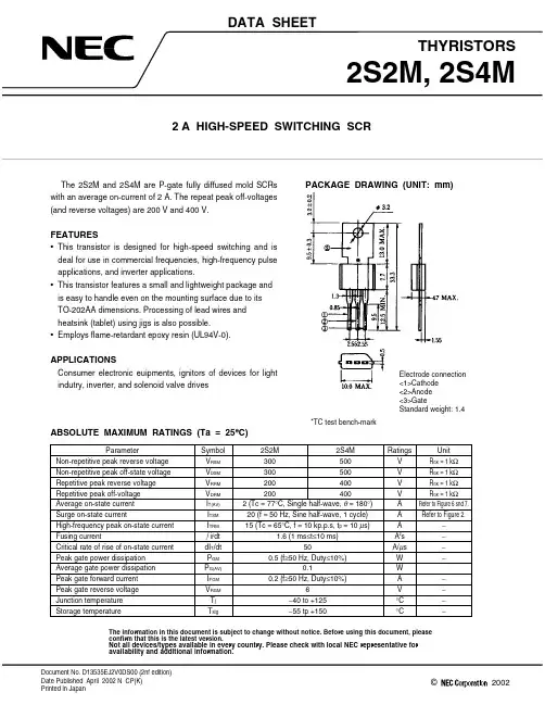
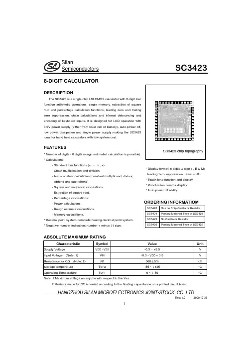
SilanSemiconductorsSC3423HANGZHOU SILAN MICROELECTRONICS JOINT-STOCK CO.,LTDRev:1.02000.12.3118-DIGIT CALCULATORDESCRIPTIONThe SC3423is a single-chip LSI CMOS calculator with8-digit fourfunction arithmetic operations,single memory,extraction of squareroot and percentage calculation functions,leading zero and trailingzero suppression,chain calculations and internal debouncing andencoding of keyboard inputs.It is designed for LCD operation with3.0V power supply(either from solar cell or battery),auto-power off,low power dissipation and single power supply making the SC3423ideal for hand held calculators with low system cost.FEATURES*Number of digits-8digits(rough estimated calculation is possible).*Calculations:-Standard four functions(+,-,x,+).-Chain multiplication and division.-Auto-constant calculation(constant multiplicand,divisor,addend and subtrahend).-Square and reciprocal calculations.-Extraction of square root.-Percentage calculations.-Power calculations.-Rough estimate calculations.-Memory calculations.*Decimal point system-complete floating decimal point system.*Negative number indication:number+minus(-)sign.SC3423chiptopographySilanSemiconductorsSC3423HANGZHOU SILAN MICROELECTRONICS JOINT-STOCK CO.,LTDRev:1.02000.12.312PADASSIGNMENTK4K6K5P1P2A5A4S1S2V DDH1a1b1c1c2b3A3A2K2K3GINTiPoV SSH3H2a9b8a8c7a5b5c5a6b6c6a7c4c3a4b4b7a2b2a3c8Note:The IC substrate should be connected to V DD in the PCB layout artwork. ELECTRICAL CHARACTERISTICS (Ta=25°C,V DD=3.0V,Unless otherwise specified) ParameterSymbolTest conditions Min Typ Max UnitV IH1V DD-0.4----Input Voltage1(Note:3)V IL1----0.4VV IH2V DD-0.4----Input Voltage2(Note:4)V IL2----0.2VI IH1V IN=V DD----1Input Current1(Note:5)I IL1V IN=0V-- 5.510µAI IH2V IN=V DD----1Input Current2(Note:6)I IL2V IN=0V----1µAI IH3V IN=V DD----1Input Current3(Note:4)I IL3V IN=0VS2=V SS51015µAI IH3V IN=V DD203040Input Current3(Note:4)I IL3V IN=0VS2=V DD----1µAV OH1without load V DD–0.15----Output Voltage1(Note:7)V OL1I OUT=15µA----0.15VV OA without load 2.80 2.95--V OB without load 1.30 1.50 1.70Output Voltage2(Note:8)V OC without load--00.20VDisplay Frequency(Note:8)F D V DD=3V,display on,Rf=560k5075--HzI OL V DD=3V,V OL=0.5V,TI=3V 1.0 1.5--Touch Tone OutputDrive Current(Note:11)I OH V DD=3V,V OH=2.5V,TI=0V 1.0 1.3--mAI DD Display off,(Note:9)----0.1Dissipation CurrentV DD1V DD=3V,display on,(Note:10)--2030µASilanSemiconductorsSC3423HANGZHOU SILAN MICROELECTRONICS JOINT-STOCK CO.,LTDRev:1.02000.12.313Rf=560k+/-5%Note:3.Applies to Pins K2–K6,TI and S2.4.Applies to Pin S1.5.Applies to Pins K2~K6and TI.6.Applies to Pin S2.7.Applies to P1,P2,A2~A5.8.Applies to H1~H3,a1~a9,b1~b8,c1~c8.9.Measured by the next test circuit after powesupply automatically yurns off.10.Measured by the next test circuit while“0”isbeing displayed after auto-clear operationand while key is not being depressed.11.Applies to POOUTPUTWAVEFORM1;HiOUTPUTWAVEFORM2ai,bi,ciPIN DESCRIPTIONPinNo.Symbol I/O DescriptionPinNo.Symbol I/O Description 1S2I APO(Auto Power Off)input25a8O Display Output(Common) 2V DD--Power Supply26b8O Display Output(Segment) 3H1O Display Output(Common)27c8O Display Output(Segment) 4a1O Display Output(Segment)28a9O Display Output(Segment) 5b1O Display Output(Segment)29H2O Display Output(Common) 6c1O Display Output(Segment)30H3O Display Output(Common) 7a2O Display Output(Segment)31V SS--Ground8b2O Display Output(Segment)32Po O Piezo Output9c2O Display Output(Segment)33Ti I Test Input10a3O Display Output(Segment)34CGout O Resistor terminal for CG 11b3O Display Output(Segment)35CGin I Resistor terminal for CG 12c3O Display Output(Segment)36K3I Key input13a4O Display Output(Segment)37K2I Key input14b4O Display Output(Segment)38A2O Strobe output15c4O Display Output(Segment)39A3O Strobe output16a5O Display Output(Segment)40A4O Strobe output17b5O Display Output(Segment)41A5O Strobe output18c5O Display Output(Segment)42P2O Strobe output19a6O Display Output(Segment)43P1O Strobe output20b6O Display Output(Segment)44K5I Key input21c6O Display Output(Segment)45K6I Key input22a7O Display Output(Segment)46K4I Key input23b7O Display Output(Segment)47S1I24c7O Display Output(Segment)SilanSemiconductorsSC3423HANGZHOU SILAN MICROELECTRONICS JOINT-STOCK CO.,LTDRev:1.02000.12.314FUNCTIONAL DESCRIPTION1. LCD DISPLAYDisplay FormatNumericalsFontSignFontMemory Error minus Punctuation Touch tone indicatorLCD ConnectionH2H3a9c8b8a8c7b7a7c6b6a6c5b5a5c4b4a4c3b3a3c2b2a2c1b1a1H1LCD Driving System1/2bias,1/3dutyDisplay ConfigurationSegment Electrode SideCommon ElectrodeSideSilanSemiconductorsSC3423HANGZHOU SILAN MICROELECTRONICS JOINT-STOCK CO.,LTDRev:1.02000.12.315Display ExampleNo.“8”ON OR OFF WAVEFORM No.“5”ON OR OFF WAVEFORMT1T2T3T4T5T6V2V1V0V2V1V0V2V1V0V2V1V0V2V1V0V2V1V0V2V1V0H3H2H1aibici"ON""OFF"ai.bi.cia b cT1T2T3T4T5T6V2V1V0V2V1V0V2V1V0V2V1V0V2V1V0V2V1V0V2V1V0H3H2H1aibici"ON""OFF"ai.bi.ci(H1H2H3)(H1H2H3)(H1H2H3)(H1H2H3)(H1H2H3)(H1H2H3)010111111 0001111012. KEYBOARD DESCRIPTIONSa)Equal Key(=)i)Performs Keyed-in operation and maintains that operation for possible use.ii)Establishes power/reciprocation calculation.SilanSemiconductorsSC3423HANGZHOU SILAN MICROELECTRONICS JOINT-STOCK CO.,LTDRev:1.02000.12.316b)Multiplication Key(x)i)Enters multiplicand.ii)Performs previous operation and displays result.c)Division Key(÷)i)Enters dividend.ii)Performs previous operation and displays result.d)Addition Key(+)i)Conditions machine for an addition.ii)Performs previous operation and displays result.e)Subtraction Key(-)i)Conditions machine for a subtraction.ii)Performs previous operation and displays result.f)Percent Key(%)The purpose of the percent key is to allow for calculation of add-on and discount.Deter mination of add-on requires the principal amount to be the first entry followed by the"+"or"x"key,with the percentage being the second entry.Depression of the percent key yields the amount to add on,such as tax or interest.Depression of the"="key adds this amount to the principal.g)Change Sign Key(+/-)Pushing the"+/-"key twice in succession causes the corresponding sign to appear and disappear.During digit entry;this function changes the sign of the entered factor.h)Power On/All Clear Key(ON/AC)i)First push power-on displays"0".ii)In the middle of a digit entry,a second push will clear all registers and memory.i)Clear Entry/Clear Key(CE/C)i)During the digit entry,the first depression will clear the entry register.And display the previous enternumber again.ii)The second push will clear all registers except memory.j)Clear Entry Key(CE)During the digit entry will clear the entry register and display number"0".k)Square Root Key()Extracts the square root of a positive number displayed in the entry register.I)Memory Plus Key(M+)i)Adds the current display to the contents of memory.ii)It will terminate a number entry.SilanSemiconductorsSC3423HANGZHOU SILAN MICROELECTRONICS JOINT-STOCK CO.,LTDRev:1.02000.12.317m)Memory Minus Key(M-)i)Subtracts the current display from the contents of memoryii)It will terminate a number entry.n)Memory Recall and Clear Key(RCM)i)First push,as RM key,transfers the contents of the memory register into the display register.ii)Second push,as CM key,clears the memory.o)Number,Decimal Key("O-9","•")The First number key in a sequence will clear the display and enter the digit in the display.Successive entries will shift the display left and enters the data in display register.The first decimal point entered is effective.An attempted entry of more than8digits or7decimal places will be ignored.p)Touch Tone( ) Keyi)When power is ON,the touchtone function is enable and the beep sound is generated output during125msand sign is displayed on LCD.ii)Selection of touchtone function is toggled by touchtone key.iii)Outputwaveform.V OAV OCf T=2kHz3. ERROR CONDITIONSa).Error DetectionSystem errors occur when:i)The integral part of any calculation result exceeds16digits.ii)The integral part of any memory calculation result exceeds8-digit or when the integral part of any addendor subtrahend to memory exceeds8-digit.iii)The integral part of a mark-up and markdown calculation result exceeds8-digit.iv)A division by zero is attempted.v)An extraction of the square root of a negative number is attempted.Rough Estimate Calculation results occur when:The integral part of the result of any one of the standard four functions,percentage,square,reciprocal,and power calculations exceeds8-digit and is equal to16-digit or less.b).Error Indicationi)System error:"0”is indicated in the first-digit position and"E"in the sign-digit position.ii)Rough Estimate Calculation result:SilanSemiconductorsSC3423HANGZHOU SILAN MICROELECTRONICS JOINT-STOCK CO.,LTDRev:1.02000.12.318The high-order8-digit of a calculation result is indicated together with"E".The location of the decimalpoint corresponds to the result of calculation times le-8,and no zero shift is performed.c).Error Releasei)System error:A system error can be released by depressing ON/AC key.ii)Rough Estimate Calculation result:A rough estimate calculation error can be released by depressing theON/AC or CE/C key.However the calculation result is not cleared by CE/C key but is retained.4. OPERATION CHARACTERISTICSa)Constant OperationThe SC3423has implied constant mode on+,-,x,÷,&,%operations.The constant is performed automatically by the"="key,"%"key,or"%"key without a constant for addition,subtraction and division while the first operand is the constant for multiplication.b)Number EntryNumbericals can be entered up to8-digit.Entries equal to9-digit or more are ignored.c)Memory ProtectionIn any error detection,the memory contents present before the error detection are protected.d)Memory IndicationIf the memory contents are a number other than zero,"M"is indicated in the sign-digit position.e)Auto Power OffIf no key is depressed for a specific period of time,the power supply will automatically turn off.This time interval up to power-off is131,072words(Approximately equal to14minutes and24seconds at Fd=52Hz, the display time of a word being equal to6ms when Fd=52Hz).3V1.5V0VOutput waveform examplef)Double Key DepressionThe order of priority,when two keys are depressed simultaneously is as follows:OFF->ON/AC->CE/C->5->6->4->ROM->·->9>M+->=->+/-->CE->+->M-->%->RMx<-<-<-0<-1<-3<-2<-CM<-7<-8<--<··g)Key Bounce Protection-Font edge:Down to l word and up to about3words.-Back edge:14words.SilanSemiconductorsSC3423HANGZHOU SILAN MICROELECTRONICS JOINT-STOCK CO.,LTDRev:1.02000.12.3195. ARITHMETIC OPERATIONSEntryDisplay12345678.Four FundamentalArithmeticCalculationsa ba+ba ba baa-babSquare Root Calculationsaa0Eabba bPercentCalculations aaa baba b/100a b/100a+a b/100a-a b/100a b100a/ba+a b/100a-a b/100Constant Calculationskbk ba kakk ca kk c/100ck bca/kc/kckb/100100a/kc100c/ka k+c b k+a kca k-b k-SilanSemiconductorsSC3423HANGZHOU SILAN MICROELECTRONICS JOINT-STOCK CO.,LTDRev:1.02000.12.3110Key Operation Display Memory RepeatedCalculationsababa ba2b+(a/b)/ba2b-ab(a b)bPowerCalculationsaab(a b)ba2a4aa3aa1/a1/a2Mixed Calculationsat|(a+b)C(c/d)C e|>108ab c de(a+b)c/d((a+b)c/d)e/108E((a+b)c/d)e/108Memory Calculationsat|(a+b)C(c/d)C e|>108a aM abMbabcdea-bMa-ba+bMc dMa+b+c dM0ME0Ma+b+c dMa-ba-ba+ba+b+c da+b+c da+b+c da+b+c da+b+c dSilanSemiconductorsSC3423HANGZHOU SILAN MICROELECTRONICS JOINT-STOCK CO.,LTDRev:1.02000.12.3111APPLICATION CIRCUITSNote: 1.The Pad34(CGout)is deleted in SC3423die.2.While using SC3425,please connect a560k¡f5%resistor between Pad34and Pad35.SilanSemiconductorsSC3423HANGZHOU SILAN MICROELECTRONICS JOINT-STOCK CO.,LTDRev:1.02000.12.3112CHIP TOPOGRAPHY11121314151617181920212223242526272829303132353638394142434445464712345678910403733TiPoV SSH3H2a9c8b8a8c7b7 S2V DDH1a1b1c1a2b2c2a3b3K4S1K6K5P1P2A5A4A3A2K2K3CGIc3a4b4c4a5b5c5a6b6c6a7Chip Size:1.630x1.640(mm2)SilanSemiconductorsSC3423HANGZHOU SILAN MICROELECTRONICS JOINT-STOCK CO.,LTDRev:1.02000.12.3113PAD COORDINATES (Unit:µm)(SC3423) PinNo.Symbol X YPinNo.Symbol X Y 1S2-75550525a8755-5002V DD-75538026b8755-3753H1-75525527c8755-2504a1-75513028a9755-1205b1-755029H275556c1-755-12530H37551307a2-755-25031V SS7552558b2-755-37532Po7553809c2-755-50033Ti75551010a3-755-63034CGout11b3-755-76535CGin66576012c3-630-76536K354076013a4-505-76537K241576014b4-380-76538A228576015c4-255-76539A316076016a5-125-76540A43576017b5-0-76541A5-9076018c5125-76542P2-21576019a6250-76543P1-34076020b6375-76544K5-47076021c6505-76545K6-59576022a7630-76546K4-75576023b7755-75547S1-75563024c7755-625Note:The original point of the coordinate is the die center.。