丹佛斯板式换热器样本
- 格式:pdf
- 大小:3.61 MB
- 文档页数:4
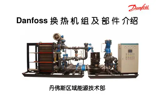
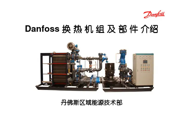
Danfoss 换热机组及部件介绍丹佛斯区域能源技术部户用小型换热机组多户用小型换热机组大型换热机组中型换热机组Danfoss 机组产品全系列机组产品全系列、、多功能设计通常要考虑设计通常要考虑::机组本身热负荷参数等 机组整体结构 客户特殊需求,如布置空间、噪音等 机组所处热力系统的水力工况设计方案量体裁衣设计方案量体裁衣,,关注客户利益机组优化设计软件机组优化设计软件,,资深的专业技术人员三维三维设计设计设计,,结构紧凑结构紧凑,,优化布局优化布局,,维修方便优化的专业设计着重细节着重细节,,追求完美细微之处见真功细微之处见真功,,Danfoss 的设计细致到每个细节的设计细致到每个细节,,精益求精精益求精。
精心选择测点位置精心选择测点位置,,保证数据采集真实准确排气装置排污装置卸压装置完备的排气完备的排气、、排污及安全卸压装置排污及安全卸压装置,,保证机组稳定运行着重细节着重细节,,追求完美细微之处见真功细微之处见真功,,Danfoss 的设计细致到每个细节的设计细致到每个细节,,精益求精精益求精。
着重细节着重细节,,追求完美细微之处见真功细微之处见真功,,Danfoss 的设计细致到每个细节的设计细致到每个细节,,精益求精精益求精。
过滤器本体具有压差检测功能过滤器的精巧设计,使得压差检测功能变得简单容易恶劣水力工况下,采用压差控制装置确保机组的温度稳定调节。
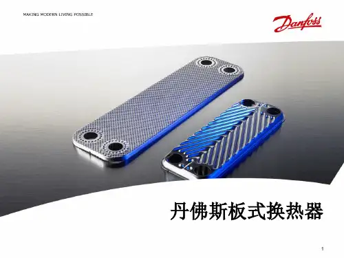
机组配置80%以上是 以上是Danfoss产品 机组配置 以上是 产品Danfoss换热器Danfoss电动调节阀Danfoss ECL 控制器Danfoss温度/压力传感器Danfoss超声波热量表Danfoss球阀Danfoss变频器Grundfos水泵Danfoss板式换热器 板式换热器• 板片厚度:0.5mm • 沟槽深度:2.8~3.9mm • 板片材质:AISI304 AISI316 • 密封垫片:NBR(丁晴) EPDM(三元乙丙) • 接口尺寸:DN32~DN300 • 接口方式:螺纹连接 法兰连接Danfoss板式换热器 板式换热器方便安装的免粘接垫片 独特的定位系统一次冲压成形确 保板片精度独特的紧固螺栓设计 卓越的导流区设计Danfoss球阀 球阀• 免维护 • 阀体为整体焊接件,易打开和关闭 • 阀门关闭严密,操作轴密封严密 • 低阻力,减少水泵能耗操作轴处的密封严密 阀门关闭严密Danfoss电动调节阀 电动调节阀• 流通能力高 • 流量特性为等百分比特性,控制性能好 • 有自检阀门行程的功能, 减少调试时工作量 • 泄漏率低 • 易于安装和操作 • 可手动操作(电手动和机械手动) • 最大口径达到DN250,最高耐温可达350℃ • 可实现控制信号分割功能 • 故障自诊断功能Danfoss电动调节阀 电动调节阀驱动器功能(AME 10/20/30/15/25/35/55/85系列 系列) 驱动器功能 系列U 2V...---V Direct 0(2)V...5(6)V Proportional LOG. flow 100% Kvs Reset1 2 3 4 5 6 7 8 9---I 0V...---V Inverse Sequential 5(6)V...10V 3 point / RL LIN. flow Red. Kvs ResetDanfoss电动调节阀 电动调节阀I• 控制信号的选择 • 控制信号起点 • 正反向动作A A B A B A B AB1U1A BA BABBABABAAB B2 (0)10V4 (0)UI20mA0V...---V0V...---VInverse11112V...---V2V...---VDirectABABABABA BABA BABA BABA BABABABABABA BABAAB BA BABAAB B0 02 410 20V mA0 010 20V mA0 010 20V mA0 0DirectInverse10 20V mADanfoss电动调节阀 电动调节阀•控制信号分割功能当两个调节阀并联时Sequential 5(6)V...10V Sequential 5(6)V...10V1A B A B AB A B A AB B1---0(2)V...5(6)VABA BABABA BAB0 05 1010 20V mA0 05 100(2)V...5(6)V---10 20V mADanfoss电动调节阀 电动调节阀• 模拟量控制和三点控制合为一体 AMV,AME3 point / RL 3 point / RL6A B6ProportionalAB24VACA BABA BABABABProportional24VACA B AB A AB B0 010 20V mADanfoss电动调节阀 电动调节阀• 改变阀门特性功能线性、等百分比特性LIN. flow77A BLOG. flowABA BABA BABABABA BABAAB B0 010 20V mA0 0LOG. flowLIN. flow10 20V mADanfoss电动调节阀 电动调节阀• Kvs值限制功能DN125 Kvs=220 DN150 Kvs=320 计算Kv=270? 建议当所选调节阀的Kvs值大于计算Kv 值20%以上时应用此功能Red. Kvs81A B8100% KvsABA BABAAB B100% Kvs100% KvsRed. Kvs82% KvsABABA BABAAB B0 010 20V mA0 010 20V mADanfoss压差控制器 压差控制器压差控制器工作原理MDV压差控制器是在水系统中用来保持某两点间压 差恒定的自力式控制阀,一般由阀体,驱动膜盒, 导压管等部分组成. 其工作原理如左图所示(左图为压差控制器控 制电动调节阀两端的压差): 电动调节阀(MDV)上游的高压通过导压管引 导至控制膜盒下侧. 电动调节阀下游的压力通过外部导压管或内部 导压孔引导至控制膜盒上侧. 由压差引起的作用力与内部弹簧的作用力相互 平衡,使调节阀两端的压差保持恒定.压差控制器侧压高侧压中侧压低调节弹簧的预紧力,即可调节压差设定值.Danfoss压差控制器 压差控制器为什么使用差压控制器?• 保持电调阀两端压差恒定——保证调节阀的调节特性,使控温准确 ——减少调节阀动作次数,延长使用寿命 ——限制全开时最大流量,反之全开时近端热站 局部“抢水”(热权度小于1)• 保证电调阀在较低的压差下工作——防止电调阀两端压差超过其最大关闭压差 ——防止出现气穴现象,降低噪音Danfoss变频器 变频器FC100系列 变频器 系列• 专为水泵、风机的应用而设计制造 • 电压矢量控制模式 • 优化的谐波性能,内置双直流电抗器 • 最佳的EMC特性,内置射频干扰滤波器 • 自动能量优化功能 • 电机自适应功能 • 双通道PID调节 • 电机友好性 • 完全的自身及电机保护 • 水泵专用功能管网水力补偿功能/无流量检测功能/睡眠功能降低能源消耗 降低噪音 水泵与管道寿命长 水泄漏降至最低Danfoss ECL控制器 控制器专用于供热和暖通空调系统的控制器 – ECL200/300 1. 使用简单, 调试时只需设定即可, 勿需任何编程 2. 操作方便, 只需简单培训工人即可操作 3. 安装简便, 运行可靠性高 4. 性价比高功能强大的可编程控制器 – ECL Apex 20 1. 使用灵活, 扩展性强 2. 组网方便, 本地化的HMI界面Danfoss ECL控制器 控制器• 气候补偿 • 分时控温 • 一次网回水温度限制 • 优化控制 • 室内温度影响ECL 200/300•功能专一,使用方便简单 • 气候补偿供暖控制或生活热水恒温控制, 根据室外温度 调节供水温度,节能舒适. •分时供暖 •PI 控制,三点可控硅输出。
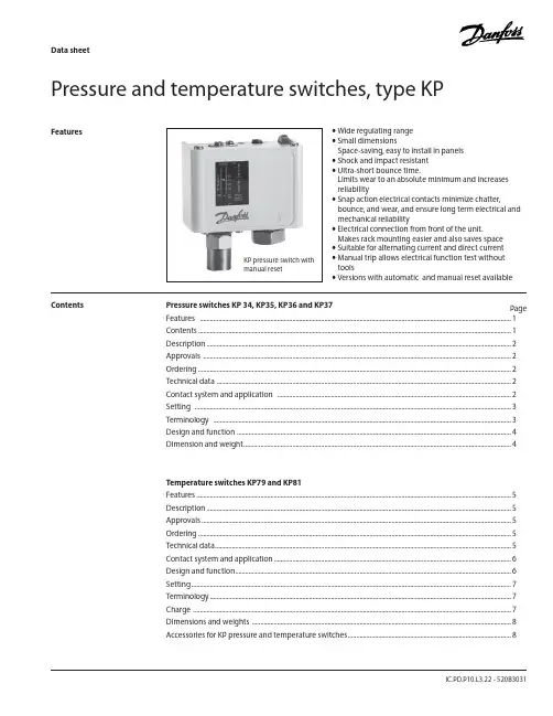
Data sheetIC.PD.P10.L3.22 - 520B3031Pressure and temperature switches, type KPFeatures• Wide regulating range • Small dimensionsSpace-saving, easy to install in panels • Shock and impact resistant • Ultra-short bounce time.Limits wear to an absolute minimum and increases reliability• Snap action electrical contacts minimize chatter,bounce, and wear, and ensure long term electrical and mechanical reliability• Electrical connection from front of the unit.Makes rack mounting easier and also saves space • Suitable for alternating current and direct current • Manual trip allows electrical function test without tools• Versions with automatic and manual reset availablePressure switches KP 34, KP35, KP36 and KP37PageFeatures .........................................................................................................................................................................................1 Contents ..........................................................................................................................................................................................1Description .....................................................................................................................................................................................2Approvals .......................................................................................................................................................................................2 Ordering ..........................................................................................................................................................................................2 Technical data ...............................................................................................................................................................................2 Contact system and application ...........................................................................................................................................2 Setting ............................................................................................................................................................................................3 Terminology .................................................................................................................................................................................3 Design and function ...................................................................................................................................................................4 Dimension and weight ...............................................................................................................................................................4 Temperature switches KP79 and KP81 Features ...........................................................................................................................................................................................5Description .....................................................................................................................................................................................5 Approvals ........................................................................................................................................................................................5 Ordering ..........................................................................................................................................................................................5 Technical data ................................................................................................................................................................................5 Contact system and application .............................................................................................................................................6 Design and function ....................................................................................................................................................................6 Setting ..............................................................................................................................................................................................7 Terminology ...................................................................................................................................................................................7 Charge .............................................................................................................................................................................................7 Dimensions and weights ..........................................................................................................................................................8Accessories for KP pressure and temperature switches .................................................................................................8 KP pressure switch with manual resetContentsDanfoss KP temperature switches are used for regulating, monitoring and alarm systems inKP thermostats are temperature-operated electricDimensions and weights©D a n f o s s A /S 07-2007, A C -D S L , m rAccessoriesfor KP pressure and temperature switches8 IC.PD.P10.L3.22 - 520B3031Danfoss can accept no responsibility for possible errors in catalogues, brochures and other printed material. Danfoss reserves the right to alter its products without notice. This also applies to products already on order provided that such alterations can be made without subsequential changes being necessary in specifications already agreed.All trademarks in this material are property of the respective companies. Danfoss and the Danfoss logotype are trademarks of Danfoss A/S. All rights reserved.。
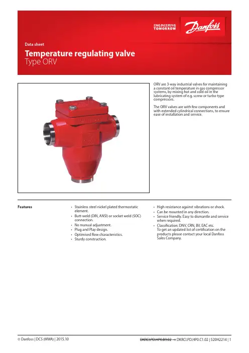
ORV are 3-way industrial valves for maintaining a constant oil temperature in gas compressor systems, by mixing hot and cold oil in the lubricating system of e.g. screw or turbo type compressors.The ORV valves are with few components and with extended cylindrical connections, to ensure ease of installation and service.Features• Stainless steel nickel plated thermostaticelement.• Butt-weld (DIN, ANSI) or socket weld (SOC)connection.• No manual adjustment.• Plug and Play design.• Optimised flow characteristics.• Sturdy construction.• High resistance against vibrations or shock.• Can be mounted in any direction.• Service friendly. Easy to dismantle and service when required.• Classification: DNV, CRN, BV, EAC etc.To get an updated list of certification on the products please contact your local Danfoss Sales Company.Technical data Oils:Applicable to all common refrigeration oils.Refrigerants:Applicable to HC, HCFC, HFC, R717 (Ammonia)and R744 (CO2).For further information please refer to installationinstruction for ORV.Temperature range:Minimum operating temperature:≥ –10°C (+14°F)Max. temperature limit based on the element temperature settings:Types Max limit43°C / 110°F77°C / 170°F49°C / 120°F82°C / 180°F60°C / 140°F93°C / 200°F77°C / 170°F110°C / 230°FPressure range:The valves are designed for a max.working pressure of 40 bar g (580 psig)Design IdentificationConnectionsAvailable with the following connections:• Butt weld DIN (EN 10220),DN 25-80 (1-3 in.)• Butt weld ANSI (B 36.10 Schedule 80),DN 25 - 40 (1 - 1½ in.)• Butt weld ANSI (B 36.10 Schedule 40),DN 50 - 80 (2 - 3 in.)• Socket Weld (ANSI B 16.11),DN 25 - 50 (1 - 2 in.)HousingMade of special, cold resistant steel approved forlow temperature operations.InstallationInstallation of the valve depends on the way itshould operate.Pressure Equipment Directive (PED)ORV valves are approved according to theEuropean standard specified in the PressureEquipment Directive and are CE marked.For further details / restrictions - see InstallationInstruction.FunctionMixing operationORV valve can work as a mixing or diverting valve. The ORV temperature regulating valve utilises the high coefficient of thermal expansion of wax to create the internal movementnecessary to have a cold and a hot inlet mixing to a common outlet. The outlet temperature will correspond to the nominal temperature of the thermostatic element.The valve house has three ports:• Port A is used for the common outlet • Port B is for the hot inlet •Port C is for the cold inletWhen the compressor unit is cold at start up, the thermostatic element will be contracted to let the full flow from port B pass until the nominal temperature (minus 5 K / 10°F ) is reached (fig. 1.1). The thermostatic element will then begin to extract to let the outlet become a mixture of hot and cold oil.When the nominal temperature is reached, the element is positioned in approximately half open position (fig. 1.2). If the temperature is reaching approximately the nominal temperature plus 5 K, the thermostatic element has been extracted to its fully open position (fig. 1.3). In this position the oil temperature will only come from the cold inlet port (C) from oil cooler.From figure 1, it can be seen how the sleeve on the element is sliding in a vertical movement. The thermostatic element is kept in position by a spring.Diverting operationDiverting operation is similar to the mixing operation. It is carried out with separation in to two of the fluid with single temperature. Due to that the temperature on the inlet is very stable fact the regulation is very smooth. The inlet temperature would correspond to the nominaltemperature of the thermostatic element.The valve house has three ports:• Port A is used for the common inlet • Port B is for the cold outlet • Port C is for the warm outletThe diverting operation otherwise is similar to the mixing operation.Application examplesExample of the system with ORV for diverting operationCapacitiesSI unitsSelection exampleOil type: Grade 68Required flow: 17 m3/hNominal oil temperature: 49°CPipe dimension: 40 mmThe upper left curve shows the viscosity of different grades of oil as a function of the temperature. The viscosity is continued into the upper right curve where the 17 m3/h must be found. The line is drawn vertically downwards into the capacity table for the ORV valve models.As shown two selections can be made:Either ORV 40 H2 with pressure drop at approx. 0.56 bar or ORV 50 H2 with pressure drop at 0.42 bar.The final selection will depend on the available pressures in the system. If the pressures are low (or can be low at certain loads) the ORV 50 H2 might be preferred. If the pressures are constantly available the pipe dimension may be taken into account and the ORV 40 H2might be preferred.CapacitiesUS unitsSelection exampleOil type: Grade 68Required flow: 75 USgal/min.Nominal oil temperature: 120°FPipe dimension: 1½”The upper left curve shows the viscosity of different grades of oil as a function of the temperature. The viscosity is continued into the upper right curve where the 75 USgal/min. must be found. The line is drawn vertically downwards into the capacity table for the ORV valve models.As shown two selections can be made:Either- ORV 1½H2 with pressure drop 8.2 psi or- ORV 2”H2 with pressure drop 6.2 psiThe final selection will depend on the available pressures in the system. If the pressures are low (or can be low at certain loads) the ORV 2" H2 might be preferred. If the pressures are constantly available the pipe dimension may be taken into account and the ORV 1½" H2might be preferred.Material specification ORV 25-80No.Part Material EN ASTM standard1Housing Steel GP240GH10213-2WCB A 2162Cover Steel GP240GH------------------------P285QH 10213-2------------------------10222-4WCB A 216------------------------A 3503Glide ring PTFE4Element*)Stainless steeland NI platedparts5Spring Steel DIN1722310270-16Gasket Non asbestos7Bolts Steel Quality 8.8ISO4017Grade 5*) The thermostatic element may look differently from one shown on the picture. All types of thermostats used by Danfoss have the same function, temperature setting and P-band.Connections DINANSISOCDimensions and weightsType codesImportant!Where products need to be certified according to specific certification societies or where higher pressures are required, the relevant information should be included at the time of ordering.Valve type ORV Oil regulating valve, high specificationNominal size in mm(valve size measured on the connection diameter)Available connections DINANSI SOC 25X X X 40X X X 50X X X65X X 80XXConnection A D SOC Butt weld connection: ANSI Butt weld connection: DIN Socket welding Valve housing3-WAY3-WAYThermostatCode no.Thermostat 43oC/110oFORV 25 and ORV 40 H1148H3466ORV 40 and ORV 50 H2148H3467ORV 65 and ORV 80 H3148H34681)Thermostat 49o C/120oFORV 25 and ORV 40 H1148H3463ORV 40 and ORV 50 H2148H3464ORV 65 and ORV 80 H3148H34651)Thermostat 60o C/140oFORV 25 and ORV 40 H1148H3469ORV 40 and ORV 50 H2148H3470ORV 65 and ORV 80 H3148H34711)Thermostat 77o C/170oFORV 25 and ORV 40 H1148H3472ORV 40 and ORV 50 H2148H3473ORV 65 and ORV 80 H3148H34741)1)For valve housing size H3 the code number includes two H2 thermostats.Complete valve housing including gasket and guide ring but without thermostat Code no.ORV 25 DIN H1148H3399ORV 25 SOC H1148H3400ORV 25 ANSI H1148H3401ORV 40 DIN H1148H3361ORV 40 DIN H2148H3402ORV 40 SOC H2148H3403OVR 40 ANSI H1148H3404ORV 40 ANSI H2148H3405ORV 50 DIN H2148H3406ORV 50 SOC H2148H3407ORV 50 ANSI H2148H3408ORV 65 DIN H3148H3409ORV 65 ANSI H3148H3410ORV 80 DIN H3148H3362ORV 80 ANSI H3148H3411ORV parts programmeExample:ORV 40 DIN H2 49°C/120°F:Thermostat element and cover gasket code number 148H3464andComplete valve housing code number 148H3402Ordering ORV valves from the parts programmePlease note:The thermostat code numbers do not include guide ring.Gasket and guide ring are included when ordering the complete valve housing but can also be ordered separately as spare parts.PartSpare parts for Code no.Gasket and guide ringORV 25 and ORV 40 H1148H3246ORV 40 and ORV 50 H2148H3247ORV 65 and ORV 80 H3148H32482)2)Including two guide rings and one gasket.ORV spare partsData sheet | Temperature regulating valve, type ORV。
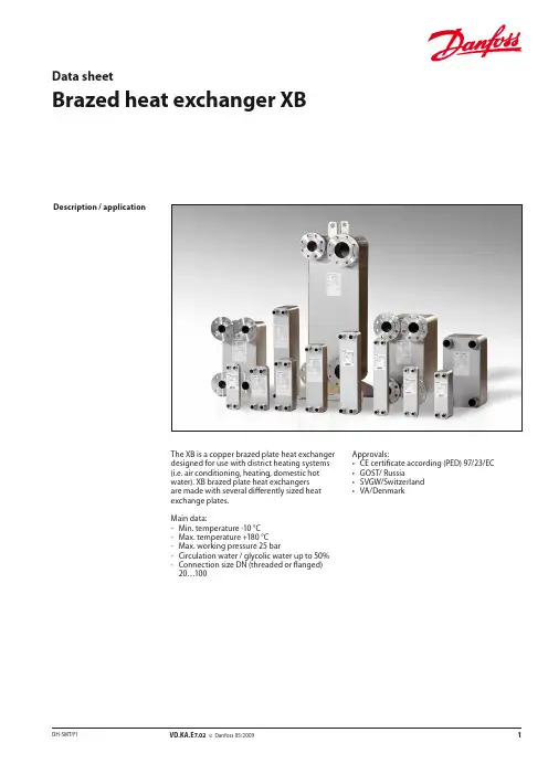

User manualInstallation, Operation and Maintenance ManualAPP pumps (APP 21-43)Service guideMicroChannel Heat Exchangers MCHEInstallation and Maintenance Guide Sevice guide | Application, Installation and Maintenance Manual MCHE2 |AX292455807588en-000101 | 01.2019Table of ContentsTable of Contents . . . . . . . . . . . . . . . . . . . . . . . . . . . . . . . . . . . . . . . . . . . . . . . . . . . . . . . . . . . . . . . . . . . . . . . . . . . . . . . . . .21 . Introduction . . . . . . . . . . . . . . . . . . . . . . . . . . . . . . . . . . . . . . . . . . . . . . . . . . . . . . . . . . . . . . . . . . . . . . . . . . . .41 .1 G eneral . . . . . . . . . . . . . . . . . . . . . . . . . . . . . . . . . . . . . . . . . . . . . . . . . . . . . . . . . . . . . . . . . . . . . . . . . . . . . . . . .41 .2 Symbols . . . . . . . . . . . . . . . . . . . . . . . . . . . . . . . . . . . . . . . . . . . . . . . . . . . . . . . . . . . . . . . . . . . . . . . . . . . . . . . .42 . Storage and working environments . . . . . . . . . . . . . . . . . . . . . . . . . . . . . . . . . . . . . . . . . . . . . . . . . . . . .52 .1 Storage . . . . . . . . . . . . . . . . . . . . . . . . . . . . . . . . . . . . . . . . . . . . . . . . . . . . . . . . . . . . . . . . . . . . . . . . . . . . . . . .52 .2 Handling . . . . . . . . . . . . . . . . . . . . . . . . . . . . . . . . . . . . . . . . . . . . . . . . . . . . . . . . . . . . . . . . . . . . . . . . . . . . . . .52 .3 Bending procedure . . . . . . . . . . . . . . . . . . . . . . . . . . . . . . . . . . . . . . . . . . . . . . . . . . . . . . . . . . . . . . . . . . . . .53 . Installation . . . . . . . . . . . . . . . . . . . . . . . . . . . . . . . . . . . . . . . . . . . . . . . . . . . . . . . . . . . . . . . . . . . . . . . . . . . . . .63 .1 Pass arrangement . . . . . . . . . . . . . . . . . . . . . . . . . . . . . . . . . . . . . . . . . . . . . . . . . . . . . . . . . . . . . . . . . . . . . .63 .2 Fan location and size . . . . . . . . . . . . . . . . . . . . . . . . . . . . . . . . . . . . . . . . . . . . . . . . . . . . . . . . . . . . . . . . . . . .63 .3 Coil mounting against thermal expansion . . . . . . . . . . . . . . . . . . . . . . . . . . . . . . . . . . . . . . . . . . . . . . .73 .4 Elimination of gaps . . . . . . . . . . . . . . . . . . . . . . . . . . . . . . . . . . . . . . . . . . . . . . . . . . . . . . . . . . . . . . . . . . . . . .83 .5 Prevention of galvanic corrosion . . . . . . . . . . . . . . . . . . . . . . . . . . . . . . . . . . . . . . . . . . . . . . . . . . . . . . . . .83 .6 Vibration . . . . . . . . . . . . . . . . . . . . . . . . . . . . . . . . . . . . . . . . . . . . . . . . . . . . . . . . . . . . . . . . . . . . . . . . . . . . . . .94 .Leak repair . . . . . . . . . . . . . . . . . . . . . . . . . . . . . . . . . . . . . . . . . . . . . . . . . . . . . . . . . . . . . . . . . . . . . . . . . . . . . .95 . Coating . . . . . . . . . . . . . . . . . . . . . . . . . . . . . . . . . . . . . . . . . . . . . . . . . . . . . . . . . . . . . . . . . . . . . . . . . . . . . . . .106 Maintenance . . . . . . . . . . . . . . . . . . . . . . . . . . . . . . . . . . . . . . . . . . . . . . . . . . . . . . . . . . . . . . . . . . . . . . . . . . .106 .1 Filters . . . . . . . . . . . . . . . . . . . . . . . . . . . . . . . . . . . . . . . . . . . . . . . . . . . . . . . . . . . . . . . . . . . . . . . . . . . . . . . . . .106 .2 Shut down periods . . . . . . . . . . . . . . . . . . . . . . . . . . . . . . . . . . . . . . . . . . . . . . . . . . . . . . . . . . . . . . . . . . . . .106 .3 Cleaning procedure . . . . . . . . . . . . . . . . . . . . . . . . . . . . . . . . . . . . . . . . . . . . . . . . . . . . . . . . . . . . . . . . . . ..10Service guide | Application, Installation and Maintenance Manual MCHE3AX292455807588en-000101 | 01.2019 |1.1 Gener a lThis guide is for installation and maintenance of Danfoss Microchannel Heat Exchangers (MCHEs) . We recommend that you read this manual carefully before commencing any work .Danfoss is not responsible or liable for any damage caused by failure to comply with the instructions in this manual and/or due to incorrect installation, operation and mainte-nance of MCHEs .All personnel being responsible for operation and maintenance of theeat exchanger unit must read and fully understand these instruc-tions before:• Transportation of the MCHE unit • Lifting the unit• Installing the MCHE unit •S ervicing the MCHE unit • Maintaining the MVHe unit•1.2 Gener alI ndicates something to be noted by thereaderI ndicates a situation which will or could result in personal injury and/or damage to the MCHE1. IntroductionSevice guide | Application, Installation and Maintenance Manual MCHE4 |AX292455807588en-000101 | 01.20192. Storage and workingenvironments• Microchannel heat exchangers should bestored indoors in a dry and clean environ-ment .• The storage temperature range is -40 °C to 121°C (-40°F to 250°F) .•Metal chips, and/or copper or steel dust can cause galvanic corrosion, so storage and installation areas must remain clean and separate from machining or welding areas . Use separate tools and/or keep tools clean .•To minimize potential damage, we recom-mend that you keep MCHEs in their original packaging until they are installed in the air conditioning or refrigeration equipment . •Improper storage and stacking of MCHEs can cause premature corrosion or deforma-tion and will reduce MCHE’s life . Extra care should be taken when storing MCHEs!• Refrigerants used in MCHE shall comply with AHRI Standard 700 .•The maximum operating pressure shall not exceed the value shown on the Label of MCHE .2.1 Stor a ge2.2 H a ndlingCompared to tube & fin coils, microchannel heat exchangers are relatively light, the fins are harder to bend and they are less likely to cut fingers . The combination of these features makes MCHEs easier to handle than tube & fin coils . However, the overall coil assembly is made of soft alu-minum, so it is susceptible to deformation (Fig .1)Fig . 1 Handling attentions2.3 Bending procedureThe same bending machines can be used for MCHE and tube & fin heat exchangers . In order to optimize costs associated with shipping and packaging, we recommend that MCHEs be shipped flat and formed at the customer’s location .Bending Radius:The minimum bend radius required to achieve acceptable manufacturing yields is a function of the microchannel tube, fin, and alloy, the overall capabilities of the bending equipment including, fixturing, bending speed and bending length .NOTE: Conducting trial bending runs of thespecific coil and configuration are recommended to verify . In general, tighter radius, thicker tubes and longer bend lines are harder to bend . Use a larger radius if possible .Recommended minimum bending radii (as determined by factory tests under favorable conditions) are shown in Table 1 for different microchannel tubes and fins . Consult with Danfoss for the tubes not listed . Do notarbitrarily extrapolate or interpolate the values .•Never lift a MCHE by the inlet and outlet tubes as it might result in dimensional deviation or worse yet, the initiation of a crack that can later result in a leak .• Do not hit or drop MCHE on edges . The MCHE is constructed of soft aluminum therefore, dropping, striking, placing heavy objects on top of, or stepping on any part of the heat exchanger will likely cause a deformation . If the coil becomes slightly deformed or bowed, it is possible to flatten them back out by laying them concave side down on a flat hard surface and applying pressure via a large heavy flat plate (say 3-4 square feet of ½” non-metallic sheet, such as plywood or plastic, with a couple of handles attached) . This procedure works for bowed coils with flush fins, but not for local fin protrusions .Table 1Service guide | Application, Installation and Maintenance Manual MCHE5AX292455807588en-000101 | 01.2019 |Consider the following during bending:• MCHEs are constructed of soft aluminumand are susceptible to deformation during handling . Prior to bending operation, make sure the MCHE is flat, square and undam-aged . Consider a sizing operation to ensure this .• Make sure the coils are loaded into thebender in a way that keeps them flat square and undamaged . • Keep the flat tubes perpendicular to thespindle while bending the coil .• Clamp the coil during the bending process,being careful not to crush it . • Slower bending speeds will often yieldbetter results .• Vertical spindle bending machines are oftenset up so that the microchannel coil ends up sliding along the table with all its weight supported by the header ends and/or the bottom dead tube .During the bending operation, do not let one end of the coil become cantilevered off the edge the table, because this can cause the coil to droop with the tubes being non-perpendicular to the spindle, resulting in corkscrewing or reduced bend quality and/or consistency . Note that with some benders, a portion of the supporting table will drop down during bending, creating opportunities for cantilever loads and improper bending .•Bending multi-bend coils on a horizontal spindle bender can cause cantilevered loads resulting from the dead weight of the unsupported bent legs . As an example, a coil with three (3) bends, depending on fixturing, may result in the load of the first 75% of the coil being transferred into the remaining coil leg, possibly causing poor bend quality and/or permanent deforma tion . Bending challenges are greater with MCHE’s than similar fin and tube coils, requiring proper fixturing .3. Inst a ll a tion 3.1 Pass arrangementCarefully identify the locations of the inlet andoutlet tubes . Microchannel condensers is often designed with multiple passages (parallel flow) that have fewer tubes in each successive pass (Fig . 2)Danfoss MCHEs include a small notch in both headers to indicate that this is the bottom of the heat exchanger . Additionally, a product label is placed on the outermost tube (unless specified elsewhere by the customer), indicating the top of the heat exchanger .Incorrectly connecting the inlet and outlet tubes of a MCHE will likely result in excessive refrige-rant side pressure drop and poor heat transfer .Fig . 2 MCHE passes distribution3.2 Fan location and sizeAir distribution may have an influence on the performance of the MCHE . For good air distribu-tion choosing a fan with proper fan diameter and keeping a constant distance between the coil and the fan is desirable . We recommend selecting a fan diameter that is as close as possible to the smallest of MCHE height and length . The distance between MCHE and fan is )recommended to be at least 15 times the width/depth of MCHE coil when possible (Fig .3) .Fig . 3 Fan location and sizeSevice guide | Application, Installation and Maintenance Manual MCHE6 |AX292455807588en-000101 | 01.20193.3 Coil mounting against thermal expan- sionThermal expansion of aluminum is higher than most other metals . Frequent thermally induced stress could shorten the life of the micro channel heat exchanger (Fig .4)Fig . 4 Coil mounting for MCHETo avoid the risk of thermal expansion, a micro channel heat exchanger must be mounted with brackets that allow some flexibility of movement . Mounting methods as indicated in Figures 5a and 5b are recommended .Fig . 5b Mounting by end plateInlet/outlet connections are not designed to be used as handles, support mating tubes, resist with mating tubes during assembly, etc . In particular:• not exposed to stress/tension . (Fig .6)aluminum inlet/outlet tubes and/orforcing is required during installation .Fig .6 Inlet/Outlet connection attentionsService guide | Application, Installation and Maintenance Manual MCHE7AX292455807588en-000101 | 01.2019 |Plastic heat shrink tubing prevents galvanic corrosion in the MCHE’s copper to aluminum joint by keeping moisture from entering the area . A minimum of 70mm length from the Cu/Al joint to the connection point is required to protect the Cu-Al brazing joint and plastic shrink tube from excessive heat during the brazing process . When brazing copper piping to the MCHE, it is recom-mended to use dry nitrogen purging along with a heat sink and/or wrapping the copper stub tube with a wet cloth to protect the Cu/Al joint and heat shrink tubing from excessive heat . This also applies to microchannel heat exchangers with aluminum inlet/outlet tubes . Depending on the location of the connections relative to the heat exchanger, a heat shield may be required to protect the MCHE’s tubes and fins from the brazing torch . The recommended pipe length “L” after the brazing joint should be greater than or equal to 70mm as shown in the picture below (Fig .7) .Fig . 7 Recommended length of inlet/outletconnections3.4 Elimination of gapsTo maximize heat transfer performance, gaps should be eliminated on both sides of the face of the MCHE . Gaps should also be eliminated on the top, bottom and sides of the MCHE so that all fan induced air is directed over the coil surface . This can be accomplished with sealing strips as shown in Fig . 8 .Fig . 8 Typical installation3.5 Prevention of galvanic corrosion Aluminum is a chemically reactive metal and will corrode when combined with most metals that are used today in industrial manufacturing . To avoid any galvanic corrosion, it is necessary to separate Al and other metals . The best way to prevent galvanic corrosion is to use plastic/rubber/foam as a means to isolate the aluminum coil from dissimilar metals (Fig 8)Sevice guide | Application, Installation and Maintenance Manual MCHE8 |AX292455807588en-000101 | 01.20193.6 Vibr a tionVibration that exceeds a specific range maycause the failure of MCHE . To avoid failure due to vibration:•Make sure vibration level meet require-ments as in table 2 .Table 2 The allowable vibration rangesService guide | Application, Installation and Maintenance Manual MCHE9AX292455807588en-000101 | 01.2019 |5. Co a tingCoating of a heat exchanger could increase corrosion resistance in certain applications and/or environmental conditions such as coastal or industrial areas, as well as situations with stagnant water or extreme wet conditions . Danfoss approved coating systems provide a controlled process for the cleaning, rinsing, and the application of the coating material with full and even coverage . Untested coating systems may not adhere properly to the aluminum surface due to the flux residue left on thealuminum surface after brazing . In addition, any small area not covered by the coating couldpotentially pose a risk of failure due to corrosion . Thermal performance may also be reduced by improper application of the coating resulting in clogging or bridging between the fin and louversWARNINGSField applied coatings are not recommended for brazed aluminum MicroChannel heat exchang-ers .Danfoss MicroChannel heat exchangers must NOT be coated using any other coating, but the ones specifically approved by Danfoss, such as certain qualified e-coating (epoxy based electrophoretic coating) suppliers or similar high-quality coating technologies . Coating of a coil using a supplier or coating process notapproved by Danfoss voids the product warranty . It may also reduce the lifetime and/or the performance of the MicroChannel heat exchanger . Consult your Danfoss Sales &Application representative for more information .6. M a inten a nceFrequent servicing is essential to maintainingthe required MCHE performance . For everyinstalled Danfoss MCHE, service records must be documented .CAUTIONPrior to servicing the MCHE, be sure to discon-nect the power supply and use lock-outmethods to prevent the power from acciden-tally being turned on .6.1 FiltersDanfoss recommends the use of air filters on the frontal face of the MCHE to lower the deposition of rain water and other contaminants that can collect on the surface of the tubes .6.2 Shut down periodsDuring periods when the MCHE is not operated for longer than a week, the MCHE must be completely cleaned following the cleaningprocedure . This practice must also be performed during short shut-down periods where corrosive deposits accumulate on the MCHE .6.3 Cleaning procedureRelative to tube & fin heat exchangers, Micro-Channel heat exchanger coils tend to accumu-late more dirt on the surface of the coil and less dirt inside the coil, making them easier to clean . Follow the steps below for proper cleaning:Step 1: Remove surface debrisRemove surface dirt, leaves, fibers, etc . with a vacuum cleaner (preferably with a brush or other soft attachment rather than a metal tube),compressed air blown from the inside out, and/or a soft bristle (not wire!) brush . Do not impact or scrape the coil with the vacuum tube, air nozzle, etc .Step 2: RinseRinse only with water . Do not use any chemicals (including those advertised as coil cleaners) to clean MicroChannel heat exchangers, as they may cause corrosion .Hose the MCHE off gently, preferably from the inside-out and top to bottom, running the water through every fin passage until it comes outclean . The fins of MicroChannel coils are stronger than traditional tube & fin coil fins but still need to be handled with care . Do not hit the coil with the hose . We recommend placing your thumb over the end of the hose rather than using the end of the nozzle to obtain a gentler spray and reduce the possibility of impact damage .We do not recommend using a pressure washer to clean the coil due to the possibility of damage .Warranty claims related to cleaning damage, especially from pressure washers, or corrosion resulting from chemical coil cleaners, will NOT be honored .Step 3: Blow dryDepending on the installation and fin geometry, MicroChannel heat exchangers could possibly retain more water compared to traditional tube & fin coils . It is advised to blow off or vacuum out the residual water from the coil to speed up drying and prevent pooling .Danfoss recommends a quarterly cleaning of the coils, as the minimum . The cleaning frequency should be increased depending on the level of dirt/dust accumulation and the environment (e .g ., coastal areas with chlorides and salts) orindustrial areas with aggressive substances .Danfoss MicroChannel Heat Exchangers (Jia Xing) Co ., Ltd .No . 8, Sangdelan Road, Wuyuan Street,Haiyan, Zhejiang Province314300 P .R . Chinawww .danfoss .com© Danfoss | DCS (im) | 2019.01AX292455807588en-000101 | 10。


萨奥丹佛斯平衡阀样本Section09_Counterbalance_valvesC o u n t e r b a l a n c e v a l v e s9.1520L0588 ? Rev DB ? November 2010* Flow ratings are based on a pressure drop of 7 bar [100 psi] unless otherwise noted. They are for comparison purposes only.Quick referenceQ u i c k r e f e r e n c eCounterbalance valves9.2520L0588 ? Rev DB ? November 2010* Flow ratings are based on a pressure drop of 7 bar [100 psi] unless otherwise noted. They are for comparison purposes only.Quick referenceQuick referenceC o u n t e r b a l a n c e v a l v e s9.3520L0588 ? Rev DB ? November 2010Application notesA p p l i c a t i o n n o t e sA counterbalance valve provides several functions:· Free flow in one direction.· Leak-free load holding.· Protection against hydraulic line failure.· Protection against pressure shocks caused by external forces or overrunning loads · Cavitation-free motion control to match speed to pump flow when a load could cause loss of control of an actuator (cylinder or motor).·Smooth, modulated motion control when the directional valve is suddenly closed.COUNTERBALANCE VALVESCounterbalance valvesMotion control valves, also referred to as load holding valves, are used to control the motion of a load in the following ways:· Prevent a load from dropping in case of hose or tube failure.· Prevent a load from drifting caused by directional control valve spool leakage.·Provide smooth, modulated motion when the load is in a lowering or run-away mode.·Provide smooth, modulated motion when the directional control valve is suddenly closed.There are two basic types of motion control valves:·Pilot-operated, or pilot-to-open check valves will satisfy the first two of the above requirements.·Counterbalance valves will satisfy all four of the above requirements.MOTION CONTROL VALVESCounterbalance valves9.4520L0588 ? Rev DB ? November 2010Application notesApplication notesCounterbalance valves will positively hold a pressurized load and willcontrol the motion of the load based on application of a pressure signal to the pilot port. Counterbalance valves are available as individual cartridges or standard cartridge-in-body (CIB)packages.Individual cartridge counterbalance valveA typical circuit application for acounterbalance valve contains a pump, directional control valve, and an actuator. Without a counterbalance valve the load will drift down due to spool leakage if the directional control valve is centered with the load raised. Additionally there is no protection against the load dropping in the event of hydraulic line failure.Circuit without a counterbalance valveCircuit with a counterbalance valveAdding a counterbalance valve controls motion and provides protection against hose or tube failure. In this circuit, moving the directional control valve to the left causes the cylinder to extend, raising the load with free flow going through the check valve portion of the counterbalance valve. When thedirectional control valve is centered, the counterbalance valve will prevent leakage and lock the load in position. Moving the directional control valve to the right sends flow/pressure to the rod end of the cylinder. This pressure also acts to pilot open the counterbalance valve and allows the load to be lowered. Should the load cause the cylinder to run away from the pump, pilot pressure to the counterbalance valve will decrease and the counterbalance valve willmodulate to match the cylinder speed to the pump flow.COUNTERBALANCE VALVES (continued)C o u n t e r b a l a n c e v a l v e s9.5520L0588 ? Rev DB ? November 2010Application notesA p p l i c a t i o n n o t e sThe pressure required to pilot open the counterbalance valve can be calculated as follows:P = (Ps ? Ab) - W (load retracts cylinder) (Ab ? R) + ArP = (Ps ? Ar) - W (load extends cylinder) (Ar ? R) + Ab W = LoadPs = Counterbalance valve relief setting; see below for more information Ab = Cylinder bore area Ar = Cylinder rod area R = Counterbalance valve pilot ratio; see below for more informationNote that these equations are idealized and do not consider any backpressure in the circuit, which is additive to the pressure required to pilot open the check valve.Some additional guideline s for counterbalance valve applications:·Specify the counterbalance valve relief setting high enough to stop any motion (flow) at the maximum expected actuatorpressure. Generally it is recommended to use a setting of 1.3 multiplied by the maximum load pressure.·Use low pilot ratios (3:1 and 4.5:1) for applications where loads may vary widely. Low pilot ratios require higher pilot pressure and are less efficient but provide stable, precise control for varying loads.·Use high pilot ratios (8:1 and 10:1) for applications where loads are relativelyconstant. High pilot ratio valves require lower pilot pressure, have faster response, and are more efficient, but lack stability and precision in response to varying loads.·Do not oversize counterbalance valves. There is no pressure drop operating limit forcounterbalance valves and in fact some pressure drop is required to maintain valve operation.·Locate counterbalance valves at or near the actuator to provide maximum load holding protection in the event of hydraulic line failure.·Do not use counterbalance valves with closed-center directional control valves. Pressure trapped between the directional control valve and the actuator can pilot the counterbalance valve open and result in undesired load motion.·Do not use counterbalance valves with tandem-center directional control valves.Backpressure in the system can prevent the counterbalance valve from opening.COUNTERBALANCE VALVES (continued)Counterbalance valves9.6520L0588 ? Rev DB ? November 2010ORDERING INFORMATIONSPECIFICATIONSDIMENSIONSOPERATIONmm [in]154 SUS (33 cSt) hyd.oil @ 100° F (38° C)573psi bar P r e s s u r e d r o p4L/min Flow 1.1US gal/min2025301452182903634358 1216202.13.24.25.3P102 375EP102 376E1P102 360ECP448-1-B -6S -E -B -150-4.5-040 SealsSeal kit B =Buna-N 120238V =Viton 120239Free flow check crack pressurebar[psi]040=2.76Pilot ratio 3.0:14.5:18.0:1Pressure rangeAdjustment option E =ExternalPilot ratio 3.0bar [psi]A =41-103[600-1500]Std.setting 69[1000]B =69-207[1000-3000]Std.setting 103[1500]C =124-345[1800-5000]Std.setting 172[2500]Pilot ratio 4.5bar [psi]A =55-172[800-2500]Std.setting 103[1500]B =103-345[1500-5000]Std.setting 172[2500]Pilot ratio 8.0bar [psi]A =103-345[1500-5000]Std.setting 172[2500]P102 102ECrack pressureCode x 10 = psiExample:150 = 1500 psiXXX = Std.setting w/no stampingHousing and ports Housing P/N 0=No Housing No Housing2B =AL,1/4 BSP CP08-3L-2B 3B =AL,3/8 BSP CP08-3L-3B 4S =AL,#4 SAE CP08-3L-4S 6S =AL,#6 SAE CP08-3L-6SOther housings available This is a pilot-operated counterbalance valve.Theoretical performanceCross-sectional viewCP448-1CP448-1Hydraulic VentC o u n t e r b a l a n c e v a l v e s9.7mm [in]520L0588 ? Rev DB ? November 2010ORDERING INFORMATIONSPECIFICATIONSDIMENSIONSOPERATION100barpsi 26 cSt [121 SUS] hyd.oil at 50°C [122°F]P 104 883P102 376E16 - 20 Nm [12-15 lbf*ft]Type E:4mmStd.setting45 = 45 bar [650 psi] Set in Spring 1 For Pilot Ratio Z 60 = 60 bar [870 psi] Set in Spring 2 For Pilot Ratio Z 70 = 70 bar [1015 psi] Set in Spring 1 For Pilot Ratio A 100 = 100 bar [1450 psi] Set in Spring 3 For Pilot Ratio Z 100 = 100 bar [1450 psi] Set in Spring 1 For Pilot Ratio B 100 = 100 bar [1450 psi] Set in Spring 2 For Pilot Ratio A,B175 = 175 bar [2537 psi] Set in Spring 3 For Pilot Ratio A,B 175 = 175 bar [2537 psi] Set in Spring 1 For Pilot Ratio C Seal kit 23000102035401519Spring RangeFor Pilot Ratio Z (1.5:1)1 = 20-70 bar [290-1015 psi]2 = 30-90 bar [435-1305 psi]3 = 50-140 bar [725-2030 psi]For Pilot Ratio A (3:1)1 = 35-110 bar [507-1595 psi]2 = 60-150 bar [870-2175 psi]3 = 80-230 bar [1160-3335 psi]For Pilot Ratio B (4.5:1)1 = 55-180 bar [797-2610 psi]2 = 75-240 bar [1087-3480 psi]3 = 90-350 bar [1305- 5075 psi]For Pilot Ratio C (10:1)1 = 90-350 bar [1305-5075 psi]Body and ports 00 = Cartridge only 6S = Aluminium,#6 SAE 8S = Aluminium,#8 SAE SE3B = Aluminium,3/8'' BSPP SE4B = Aluminium,1/2'' BSPP Seals B = Buna-N V =Viton CB10-HV-1-A-1-E-70-B-XXXXAdjustment typeE = external adjustmentF = tamper resistant Body Nomenclature No Body SDC10-3S-6S SDC10-3S-8S SDC10-3S-SE3B SDC10-3S-SE4B Pilot Ratio Z = 1.5 to 1A = 3 to 1B = 4.5 to 1C = 10 to 1P103 324EThis is a pilot-operated counterbalance valve.Theoretical performanceCross-sectional viewC B 10 H VCB10-HVHydraulic VentCounterbalance valves9.8mm [in]520L0588 ? Rev DB ? November 2010 ORDERING INFORMATION SPECIFICATIONSDIMENSIONSOPERATIONP102 376E1P102 355ECP441-1-B -12S -E -B -250-4.5-015SealsSeal kit B =Buna-N 120335V =Viton120336Pressure rangeAdjustment optionE =External adjustmentPilot ratio 3.0bar [psi]A =34-103[500-1500]Std.setting 69[1000]B =103-207[1500-3000]Std.setting 172[2500]Pilot ratio 4.5bar [psi]A =34-138[500-2000]Std.setting 103[1500]B =103-345[1500-5000]Std.setting 207[3000]Pilot ratio 10.0bar [psi]A =69-345[1000-5000]Std.setting 172[2500]Free flow check CrackPressurebar[psi]005=.34[5]015=1.03[15]P102 097EPilot ratio 3.0:14.5:110.0:1Crack pressure Code x 10 = psiExample:250 = 2500 psiXXX=Std.setting w/no stampingHousing and ports Housing P/N 0=No Housing No Housing 4B =AL,1/2 BSP CP12-3S-4B/2B 6B =AL,3/4 BSP CP12-3S-6B/2B 10S =AL,#10 SAE CP12-3S-10S/4S 12S =AL,#12 SAE CP12-3S-12S/4SOther housings availableThis is a pilot-operated counterbalance valve.Cross-sectional viewCP441-1CP441-1Hydraulic VentC o u n t e r b a l a n c e v a l v e s9.9mm [in]520L0588 ? Rev DB ? November 2010ORDERING INFORMATIONSPECIFICATIONSDIMENSIONSOPERATION154 SUS (33 cSt) hyd.oil @ 100° F (38° C)229psi bar P r e s s u r e d r o p50L/minFlow 13.2US gal/min 4681012145887116145174203100 150********.439.652.866.0P103 320P102 376E1/4 inCP443-1-B -16S -E -A -100-3.0-015SealsSeal kit B =Buna-N 120380V =Viton120381Pressure rangeAdjustment option E =ExternalPilot ratio 3.0bar [psi]A =34-103[500-1500]Std setting 69[1000]B =103-207[1500-3000]Std setting 172[2500]Pilot ratio 4.5bar [psi]A =34-138[500-2000]Std setting 103[1500]B=103-345[1500-5000]Std setting 207[3000]Pilot ratio 10.0bar [psi]A =69-345[1000-5000]Std setting 172[2500]Free flow check Cracking Pressurebar [psi]015=1.00[15]P103 257Pilot ratio =3.0 3.0:14.5 = 4.5:110.0 = 10.0:1Cracking pressureCode x 10 = psiExample:100 = 1000 psiXXX = Std.setting w/no stampingHousing and ports Housing P/N 0=No Housing No Housing 8B =AL,1 BSP CP20-3S-8B/2B 10B =AL,1-1/4 BSP CP20-3S-10B/2B 16S =AL,#16 SAE CP20-3S-16S/4S 20S =AL,#20 SAE CP20-3S-20S/4SOther housings available This is a pilot-operated counterbalance valve.Theoretical performanceCross-sectional viewC P 443-1CP443-1Hydraulic VentCounterbalance valves9.10mm [in]520L0588 ? Rev DB ? November 2010ORDERING INFORMATIONSPECIFICATIONSDIMENSIONSOPERATION100barpsi 26 cSt [121 SUS] hyd.oil at 50°C [122°F]P 104 883P103 325Type E:4mmStd.setting45 = 45 bar [650 psi] Set in Spring 1 For Pilot Ratio Z 60 = 60 bar [870 psi] Set in Spring 2 For Pilot Ratio Z 70 = 70 bar [1015 psi] Set in Spring 1 For Pilot Ratio A 100 = 100 bar [1450 psi] Set in Spring 3 For Pilot Ratio Z 100 = 100 bar [1450 psi] Set in Spring 1 For Pilot Ratio B 100 = 100 bar [1450 psi] Set in Spring 2 For Pilot Ratio A,B175 = 175 bar [2537 psi] Set in Spring 3 For Pilot Ratio A,B 175 = 175 bar [2537 psi] Set in Spring 1 For Pilot Ratio C Seal kit 23000102035401519Spring RangeFor Pilot Ratio Z (1.5:1)1 = 20-70 bar [290-1015 psi]2 = 30-90 bar [435-1305 psi]3 = 50-140 bar [725-2030 psi]For Pilot Ratio A (3:1)1 = 35-110 bar [507-1595 psi]2 = 60-150 bar [870-2175 psi]3 = 80-230 bar [1160-3335 psi]For Pilot Ratio B (4.5:1)1 = 55-180 bar [797-2610 psi]2 = 75-240 bar [1087-3480 psi]3 = 90-350 bar [1305- 5075 psi]For Pilot Ratio C (10:1)1 = 90-350 bar [1305-5075 psi]Body and ports 00 = Cartridge only 6S = Aluminium,#6 SAE 8S = Aluminium,#8 SAE SE3B = Aluminium,3/8'' BSPP SE4B = Aluminium,1/2'' BSPP Seals B = Buna-N V =Viton CB10-AV-1-A-1-E-70-B-XXXXAdjustment typeE = external adjustmentF = tamper resistant Body Nomenclature No Body SDC10-3S-6S SDC10-3S-8S SDC10-3S-SE3B SDC10-3S-SE4B Pilot Ratio Z = 1.5 to 1A = 3 to 1B = 4.5 to 1C = 10 to 1P103 327E This is a pilot-operated counterbalancevalve with an atmospheric vent.Theoretical performanceCross-sectional viewCB10 AVCB10-AVAtmospheric VentC o u n t e r b a l a n c e v a l v e s9.11520L0588 ? Rev DB ? November 2010 ORDERING INFORMATION SPECIFICATIONSDIMENSIONSOPERATION50100150200250psibar US gal/minPressure dropP103 758E10mm128Max17mm 13-17 Nm [9-12 lbf*ft][2.6][0.63]3[?1.48]37.5165-70 Nm [47-52 lbf*ft]38mmM 33x2P103 747Spring range Pilot ratio A & C1=25 to 140 bar [363 to 2031 psi]2=70 to 250 bar [1015 to 3626 psi]3=105 to 350 bar [1523 to 5076 psi]Pilot ratio B 1=25 to 120 bar [363 to 1740 psi]2=60 to 200 bar [870 to 2901 psi]3=90 to 280 bar [1305 to 4061 psi]SealsV =VitonPilot ratio:A = 6.9:1B = 4.7:1VCB 12-CN-2-A-SE3/8-VP103 859Housing and ports Housing P/N 00=No Housing No Housing SE1/2=AL,1/2 BSP NCS12/3-SE-1/2SE3/4=AL,3/4 BSP NCS12/3-SE-3/4SE8S =AL,#8 SAE NCS12/3-SE-8S SE12S =AL,#12 SAE NCS12/3-SE-12SOther housings availableSeal kit 230000360To order this valve with a specific factory setting,contact yourSauer-Danfoss representativeOmit = Buna N230000130This is a pilot-operated counterbalance valve with an atmospheric vent.Theoretical performanceCross-sectional viewV C B 12-C NVCB 12-CNAtmospheric VentCounterbalance valves9.12520L0588 ? Rev DB ? November 2010ORDERING INFORMATIONSPECIFICATIONSDIMENSIONSOPERATIONmm [in]This valve is a dual counterbalance valve with make up checks. Cross-sectional view1EEC111EEC11Dual CounterbalanceC o u n t e r b a l a n c e v a l v e s9.13mm [in]520L0588 ? Rev DB ? November 2010 ORDERING INFORMATION SPECIFICATIONSDIMENSIONSOPERATIONP102 379EP102 74988.90CP448-2-4S-B-0-E-B-150-4.5-040 Housing and ports4S = AL,#4 SAE 6S = AL,#6 SAEother housings available,consult factory SealsSeal kits B = Buna N 120238V =Viton 120239Adjustment option E = External Check crack pressure 040= 2.8 bar [40 psi] Crack pressure Code x 10 = psi Example:050 = 500 psi1.5 3.0 4.58.0A14-55 bar 41-124 bar 55-186 bar 103-345 bar [200-300 psi][600-1800 psi][800-2700 psi][1500-5000 psi]C55-207 bar 124-345 bar [800-3000 psi][1800-5000 psi]Pilot ratioPressure range B 34-117 bar 69-241 bar 103-345 bar [500-1700 psi][1000-3500 psi][1500-5000 psi]P102 750EThis valve is a dual counterbalance valve. It uses two CP448-1 cartridges.Cross-sectional viewC P 448-2CP448-2Dual CounterbalanceCounterbalance valves9.14mm [in]520L0588 ? Rev DB ? November 2010SPECIFICATIONSOPERATIONP102 379E100barpsi 26 cSt [121 SUS] hyd.oil at 50°C [122°F]P 104 883Seal kit 1100267211002673Body and ports Body P/N 6S = Aluminium,#6 SAE8S = Aluminium,#8 SAE 11001779SE3B = Aluminium,3/8'' BSPP 922518510SE4B = Aluminium,1/2'' BSPP 922518610SealsB = Buna-N V =VitonDCB10-HV-1-B-1-E-100-B-8SAdjust typeE = External adjustmentF =Tamper resistantPilot ratio Z = 1.5 to 1A = 3 to 1B = 4.5 to 1C = 10 to 1Check crack pressure1 = 1 bar (14.5 psi)Std.setting45 = 45 bar [650 psi] Set in Spring 1 For Pilot Ratio Z 60 = 60 bar [870 psi] Set in Spring 2 For Pilot Ratio Z 70 = 70 bar [1015 psi] Set in Spring 1 For Pilot Ratio A 100 = 100 bar [1450 psi] Set in Spring 3 For Pilot Ratio Z 100 = 100 bar [1450 psi] Set in Spring 1 For Pilot Ratio B 100 = 100 bar [1450 psi] Set in Spring 2 For Pilot Ratio A,B 175 = 175 bar [2537 psi] Set in Spring 3 For Pilot Ratio A,B 175 = 175 bar [2537 psi] Set in Spring 1 For Pilot Ratio CSpring rangeFor plot ratio Z (1.5:1)1 = 20-70 bar [290-1015 psi]2 = 30-90 bar [435-1305 psi]3 = 50-140 bar [725-2030 psi]For pilot ratio A (3:1)1 = 35-110 bar [507-1595 psi]2 = 60-150 bar [870-2175 psi]3 = 80-230 bar [1160-3335 psi]For pilot ratio B (4.5:1)1 = 55-180 bar [797-2610 psi]2 = 75-240 bar [1087-3480 psi]3 = 90-350 bar [1305- 5075 psi]For pilot ratio C (10:1)1 = 90-350 bar [1305-5075 psi]11002669P 104 884S6S = Steel, #6 SAE 11009171S6S = Steel, #8 SAE 11009170This is a dual counterbalance valve with hydraulic vent. This assembly uses 2 CB10-HV cartridges.210 bar with aluminum housingTheoretical performanceCross-sectional view SAE - PortedDCB10-HVDCB10-HVDual CounterbalanceC o u n t e r b a l a n c e v a l v e s9.15mm [in]520L0588 ? Rev DB ? November 2010ORDERING INFORMATIONSPECIFICATIONSDIMENSIONSOPERATION154 SUS (33 cSt) hyd.oil @ 100° F (38° C)573psi bar P r e s s u r e d r o pL/min Flow10.6US gal/min101520253014521829036343521.131.7P102 368EP102 379ECP441-2-12S -B -E -B -250-4.5-015Seals Seal kit B =Buna-N 120414V =Viton 120415Housing and ports Housing P/N 10S = AL,#10 SAE 22075212S= AL,#12 SAE 2207536B =AL,3/4 BSP 4B =AL,1/2 BSPother housings available,consult factory Free flow check Cracking pressurebar [psi]005=.34[5]015=1.03[15]Pilot ratioPressure rangeAdjustment optionE =External adjustmentPilot ratio 3.0bar [psi]A =34-103[500-1500]Std.setting 69[1000]B =103-207[1500-3000]Std.setting 103[1500]Pilot ratio 4.5bar [psi]A =34-138[500-2000]Std.setting 103[1500]B =103-345[1500-5000]Std.setting 103[1500]Pilot ratio 10.0bar [psi]A =69-345[1000-5000]Std.setting 172[2500]B =N/a N/a P102 089ECrack pressureCode x 10 = psiExample:250 = 2500 psi This valve is a dual counterbalance valve. It uses two CP441-1 cartridges.Theoretical performanceCross-sectional viewC P 441-2CP441-2Dual CounterbalanceCounterbalance valvesCounterbalance valves 9.16mm [in]520L0588 ? Rev DB ? November 2010SPECIFICATIONSOPERATION100barpsi 26 cSt [121 SUS] hyd.oil at 50°C [122°F]P 104 883P104 885Seal kit 1100267211002673Body and ports Body P/N 6S = Aluminium,#6 SAE8S = Aluminium,#8 SAE11001779SE3B = Aluminium,3/8'' BSPP 922518510SE4B = Aluminium,1/2'' BSPP 922518610SealsB = Buna-N V =VitonDCB10-AV-1-B-1-E-100-B-8SAdjust typeE = External adjustmentF =Tamper resistantPilot ratio Z = 1.5 to 1A = 3 to 1B = 4.5 to 1C = 10 to 1Check crack pressure1 = 1 bar (14.5 psi)Std.setting45 = 45 bar [650 psi] Set in Spring 1 For Pilot Ratio Z 60 = 60 bar [870 psi] Set in Spring 2 For Pilot Ratio Z 70 = 70 bar [1015 psi] Set in Spring 1 For Pilot Ratio A 100 = 100 bar [1450 psi] Set in Spring 3 For Pilot Ratio Z 100 = 100 bar [1450 psi] Set in Spring 1 For Pilot Ratio B 100 = 100 bar [1450 psi] Set in Spring 2 For Pilot Ratio A,B 175 = 175 bar [2537 psi] Set in Spring 3 For Pilot Ratio A,B 175 = 175 bar [2537 psi] Set in Spring 1 For Pilot Ratio CSpring rangeFor plot ratio Z (1.5:1)1 = 20-70 bar [290-1015 psi]2 = 30-90 bar [435-1305 psi]3 = 50-140 bar [725-2030 psi]For pilot ratio A (3:1)1 = 35-110 bar [507-1595 psi]2 = 60-150 bar [870-2175 psi]3 = 80-230 bar [1160-3335 psi]For pilot ratio B (4.5:1)1 = 55-180 bar [797-2610 psi]2 = 75-240 bar [1087-3480 psi]3 = 90-350 bar [1305- 5075 psi]For pilot ratio C (10:1)1 = 90-350 bar [1305-5075 psi]P 104 88711002669S6S = Steel, #6 SAE 11009171S6S = Steel, #8 SAE 11009170This is a dual counterbalance valve with atmospheric vent. This assembly uses the CB10-AV valve.210 bar with aluminum housingTheoretical performanceDCB10-AVDCB10-AVDual Counterbalance Cross-sectional view。
© by SEMIKRONRev. 0.7–18.10.20211®E1Half-Bridge (Full SiC)Engineering Sample SK40MB120CR03TE1Target Data Features*•Optimized design for superior thermal performance•Extremely low inductance design •Press-Fit contact technology •1200V Planar Gen3 SiC MOS•Simple to drive with +15V gate voltage •Integrated NTC temperature sensor •UL recognized file no. E 63 532Typical Applications•Switched Mode Power Supplies •Energy Storage Systems •Electric Vehicle charging •UPS •Solar •Motor DrivesRemarks•Recommended T j,op =-40 ...+150 °C •Recommended turn-off / turn-on gate voltage V GS = -4...0/+15VFootnotes1) SEMIKRON Exclusive High PerformanceThermal Paste (HPTP), available as pre-appliedAbsolute Maximum Ratings SymbolConditions Values UnitMOSFET 1V DSS 1200V I D T j =175°CT s =25°C 49A T s =70°C41A I DMPulse width t p limited by T jmax120A I DM,repetitive60A V GS Max. transient gate - source voltage-8...19V T j-55 (175)°C Integrated body diode I FMPulse width t p limited by T jmax120A I FM,repetitive60AAbsolute Maximum Ratings SymbolConditions Values UnitModule I t(RMS)∆T terminal at PCB joint = 30 K, per pin 30A T stg module without TIM -40...125°C V isolAC, sinusoidal, t =1min2500V2Rev. 0.7–18.10.2021© by SEMIKRON®E1Half-Bridge (Full SiC)Engineering Sample SK40MB120CR03TE1Target Data Features*•Optimized design for superior thermal performance•Extremely low inductance design •Press-Fit contact technology •1200V Planar Gen3 SiC MOS•Simple to drive with +15V gate voltage •Integrated NTC temperature sensor •UL recognized file no. E 63 532Typical Applications•Switched Mode Power Supplies •Energy Storage Systems •Electric Vehicle charging •UPS •Solar •Motor DrivesRemarks•Recommended T j,op =-40 ...+150 °C •Recommended turn-off / turn-on gate voltage V GS = -4...0/+15VFootnotes1) SEMIKRON Exclusive High PerformanceThermal Paste (HPTP), available as pre-appliedCharacteristics SymbolConditions min.typ.max.UnitMOSFET 1V (BR)DSS V GS =0V,I D =0.1mA, T j =25°C 1200V V GS(th)V DS =V GS , I D =11.5mA, T j =25°C 1.82.53.6V I DSS V GS =0V,V DS =1200V, T j =25°C 1mA I GSS V DS =0V,V GS =15V,T j =25°C 100nA R DS(on)V GS =15V I D =41AchiplevelT j =25°C 3243m ΩT j =150°C 50m ΩC iss V GS =0V,V DS =1000V, f =0.1MHz 3400pF C oss V GS =0V,V DS =1000V, f =0.1MHz 130pF C rss V GS =0V,V DS =1000V, f =0.1MHz 10pF R Gint T j =25°C1.7ΩQ G V DD = 800 V, V GS = -4 V ... 15 V, I D =41A 118nC t d(on)V DD =600V V GS =15/-4V I D =40AR Gon =12ΩR Goff =12Ωdi/dt off =2.8kA/µs di/dt on =3.6kA/µsdv/dt =56kV/µsT j =150°C 36ns t d(off)T j =150°C 90ns t r T j =150°C16ns t f T j =150°C 23ns E on T j =150°C 0.56mJ E off T j =150°C0.35mJ R th(j-s)per MOSFET, λpaste =2.5 W/(mK) 1)1.02K/W Integrated body diodeV F = V SD -I D =21AV GS =-4V chiplevelT j =25°C 4.62V T j =150°C 4.31V V F0 = V SD0chiplevel T j =25°C 3.80V T j =150°C 3.60V r F = r SD chiplevelT j =25°C 39m ΩT j =150°C 34m Ωt rr V DD =600V -I D =40A V GS =-4V R Gon =12Ωdi/dt off =3.7kA/µsT j =150°C 33ns Q rr T j =150°C 0.7µC I rr T j =150°C 43A E rrT j =150°C0.41mJCharacteristics SymbolConditions min.typ.max.UnitModule L CE 9nH M s to heatsink 1.62.3Nm wweight25gCharacteristics SymbolConditionsmin.typ.max.UnitTemperature SensorR 100T r =100°C493 ± 5%ΩB 100/125R (T)=R 100exp[B 100/125(1/T-1/T 100)]; T[K];3550 ±2%K© by SEMIKRON Rev. 0.7–18.10.202134Rev. 0.7–18.10.2021© by SEMIKRON© by SEMIKRON Rev. 0.7–18.10.202156Rev. 0.7–18.10.2021© by SEMIKRONThis is an electrostatic discharge sensitive device (ESDS) due to international standard IEC 61340.*IMPORTANT INFORMATION AND WARNINGSThe specifications of SEMIKRON products may not be considered as guarantee or assurance of product characteristics ("Beschaffenheitsgarantie"). The specifications of SEMIKRON products describe only the usual characteristics of products to be expected in typical applications, which may still vary depending on the specific application. Therefore, products must be tested for the respective application in advance. Application adjustments may be necessary. The user of SEMIKRON products is responsible for the safety of their applications embedding SEMIKRON products and must take adequate safety measures to prevent the applications from causing a physical injury, fire or other problem if any of SEMIKRON products become faulty. The user is responsible to make sure that the application design is compliant with all applicable laws, regulations, norms and standards. Except as otherwise explicitly approved by SEMIKRON in a written document signed by authorized representatives of SEMIKRON, SEMIKRON products may not be used in any applications where a failure of the product or any consequences of the use thereof can reasonably be expected to result in personal injury. No representation or warranty is given and no liability is assumed with respect to the accuracy, completeness and/or use of any information herein, including without limitation, warranties of non-infringement of intellectual property rights of any third party. SEMIKRON does not assume any liability arising out of the applications or use of any product; neither does it convey any license under its patent rights, copyrights, trade secrets or other intellectual property rights, nor the rights of others. SEMIKRON makes no representation or warranty of non-infringement or alleged non-infringement of intellectual property rights of any third party which may arise from applications. Due to technical requirements our products may contain dangerous substances. For information on the types in question please contact the nearest SEMIKRON sales office. This document supersedes and replaces all information previously supplied and may be superseded by updates. SEMIKRON reserves the right to make changes.In accordance with the quality guidelines of SEMIKRON, we would like to point out that the products are engineering samples. These engineering samples are not yet produced under quality conditions approaching those of series production, and are at the present time not included in the SEMIKRON quality monitoring and control process. Neither the product nor the production process has to date gone completely through the SEMIKRON internal authorization procedure. SEMIKRON may make any amendments without any prior notification. SEMIKRON cannot and shall not promise or commit itself to release and/or make available a final version or series product after the development phase. SEMIKRON cannot and will not assume any responsibility with regard to freedom from defects, functionality, and adaptation to and interaction with possible applications of the user or with regard to any other potential risks resulting from the use of engineering samples. Therefore SEMIKRON explicitly excludes any warranty and liability; as far as legally possible. The customer shall fully indemnify and hold harmless SEMIKRON from any and all risks, damages, losses, expenses and costs directly or indirectly resulting out of or in connection with the commissioning, operation, system integration, sale, dissemination or any other kind of use of engineering samples by the customer and/or any third party, which has come into possession of engineering samples through or because of the customer. All know-how and all registerable and non-registerable copyrights and industrial property rights arising from or in connection with these engineering samples remain the exclusive property of SEMIKRON.7。